Article

Influence of Spatter on Porosity, Microstructure, and Corrosion of Additively Manufactured Stainless Steel Printed Using Different Island Size

1
Department of Materials Science and Engineering, North Carolina State University, Raleigh, NC 27695, USA
2
Physical and Computational Sciences Directorate, Pacific Northwest National Laboratory, Richland, WA 99354, USA
3
Department of Mechanical and Aerospace Engineering, North Carolina State University, Raleigh, NC 27695, USA
*
Authors to whom correspondence should be addressed.
Crystals 2024, 14(4), 328; https://doi.org/10.3390/cryst14040328
Submission received: 9 January 2024 / Revised: 27 March 2024 / Accepted: 29 March 2024 / Published: 30 March 2024
(This article belongs to the Special Issue Corrosion Phenomena in Metals)

Abstract

:
Specimens of 316 L stainless steel were printed using laser powder bed fusion (LPBF), a popular metal additive manufacturing (AM) technique, with varying island sizes. Not many researchers have considered the impact of spatter while optimizing LPBF printing parameters. In this research, the influence of spatter was considered while also investigating the effect of varied island size on the microstructure, surface roughness, microhardness, and corrosion resistance of LPBF-316 L. No correlation was observed between surface roughness or microhardness and minor variations in island size. However, a correlation was drawn between varied island sizes and porosity in LPBF-316 L. The specimens associated with larger island sizes showed significantly enhanced corrosion resistance due to fewer manufacturing defects and reduced porosity, attributed to the minimal influence of the spatter. Based on analysis, the LPBF parameters were revised, which lead to superior corrosion resistance of LPBF-316 L, attributed to high density and reduced porosity.

1. Introduction

Additive manufacturing (AM) uses a laser or electron beam to melt input powder and produce final net-shaped components by employing 3D computer-aided design models [1,2,3]. AM techniques are suitable for printing complex shapes and compositions due to their layer-by-layer process and high solidification rates. As a result, these techniques are beginning to replace many conventional manufacturing processes, such as forging and casting [4,5,6,7]. Laser powder bed fusion (LPBF) is a popular metal additive manufacturing (AM) technique that has been used for printing different metallic systems, including iron, magnesium, and aluminum alloys [8,9,10,11,12,13,14]. The melt is exposed to extreme temperatures (3000–4000 °C) and (104–107 K/s) solidification rates during the LPBF process [4,15,16]. LPBF stainless steels (SS) have been extensively studied due to their diverse applications, ranging from kitchen knives to nuclear reactors [17,18,19,20].
Over the past two decades, LPBF processes have been extensively studied with the aim of integrating them into mainstream manufacturing [4,21,22,23,24,25,26,27,28]. However, poor surface finish and porosity have been reported to deteriorate the mechanical and corrosion properties of LPBF alloys [15,29,30,31,32,33]. Therefore, recent studies have been focused on understanding the influence of different LPBF parameters on porosity and microstructure, and correlating them with properties [4,34,35]. Several researchers [36,37,38,39] have reported improved mechanical and corrosion properties as a result of optimizing the LPBF parameters. The influence of different LPBF parameters, such as laser power, laser energy density, laser scanning speed, layer thickness, hatch spacing, building orientation, chamber gas, laser spot size, laser scanning strategy, point distance, and exposure time, on the microstructure and properties of LPBF printed 316 L has been studied in the literature [4,15,21,30,39,40,41,42,43]. However, the influence of LPBF parameters like island size on manufacturing defects, microstructure, and corrosion properties observed in LPBF printed 316 L has not been explored in detail. Moreover, the influence of spatter on the properties of LPBF printed 316 L has gathered very limited attention [44,45,46].
Several researchers [47,48,49,50,51,52,53,54] have explored the influence of laser scanning strategies on mechanical properties, such as tensile strength and microhardness. Using varying strategies such as checkerboard/island, stripe with and without contour, and meander, Salmon et al. [48] observed variations in ultimate tensile strength from 600–1000 MPa. The underlying mechanisms causing these modifications are not fully understood, but it is evident that laser scanning strategies play a crucial role in controlling the thermal history experienced by the powder bed during LPBF. The thermal history, in turn, significantly affects grain size, texture, residual stresses, and defect density, and ultimately impacts the mechanical and corrosion properties of the alloy [55]. While substantial research has been conducted on understanding the influence of different laser scanning strategies, there has been limited exploration into the impact of minor changes within a single scanning strategy on alloy properties. Instead of introducing multiple influencing factors such as varied scanning strategies, rotation vectors, or remelting between layers, focusing on one specific influencing factor of a particular scanning strategy can unravel the underlying mechanisms of that factor and reveal whether minor changes within a scanning strategy can impact alloy properties.
The island strategy, a widely employed approach in LPBF [4,47,48,49,50,51,52,54] divides each layer into multiple squares/islands that are randomly printed, completing the layer. Scan vectors of adjacent islands are perpendicular, resulting in tracks scanned in multiple directions, and achieving high densification with uniform powder melting. While the island strategy is recognized for producing high-quality parts, limited research [53,56] has explored the impact of varied island sizes on mechanical properties. For instance, Wu et al. [56] reported a 13% reduction in tensile residual stress by varying the island size from 5 × 5 mm2 to 3 × 3 mm2. The reduced residual stress could be attributed to the stress relaxation of shorter scan vectors. However, the impact of island size on corrosion properties remains largely unexplored.
The phenomenon of powder particles being ejected and scattered around the build area is commonly referred to as spatter. Spatter can manifest as various types, formed due to different mechanisms [57,58,59]: (1) Solid spatter. Unmelted powder ejected by vapor jet before sufficient laser melting, impacting powder layer uniformity. (2) Metallic jet spatter. Liquid droplets ejected from the depression zone due to intense metallic vapor, influenced by vapor pressure and shear forces. (3) Powder agglomeration spatter. Powders and spatters agglomerate to form larger spatters due to vaporization and collision processes. (4) Entrainment melting spatter. Solid powders entrained by ambient gas flow melted by laser, leading to spatter formation. (5) Defect-induced spatter. Characterized by the interaction of laser with severe defects such as large pores, causing a sudden eruption of liquid spatter and impacting part quality [44,60].
Researchers [4,44,45,46,61] have reported different morphologies of spatter particle surfaces. LPBF-316 L alloy printed with different spatter morphologies has shown variations in inclusion size, frequency, and composition. Liu et al. [44] presented the declined ultimate tensile strength (UTS) of LPBF-316 L alloy printed using spatter-contaminated powder, attributing the decreased properties to the high density of inclusions in the alloy. Some researchers [60] have reported the presence of δ-ferrite in reused powder with spatter and claimed that magnetic properties were different for fresh and reused powders. Additionally, Pinto et al. [60] reported a high defect density, including porosity, delamination, warping, and lack of fusion in LPBF-316 L alloy printed using spatter-contaminated powders. These microstructural changes induced by spatter can indeed affect corrosion properties as well. However, numerous studies have concentrated on adjusting processing parameters to attain high specimen density, often overlooking spatter. Not many researchers have systematically considered spatter, nor investigated the correlation between spatter-induced microstructural changes and the corrosion properties of LPBF-316 L.
Therefore, this research addresses the knowledge gap and focuses on understanding the influence of spatter in determining the porosity, microstructure, and properties of LPBF printed 316 L with different island sizes. In this study, 316 L coupons with four island sizes (5 × 5, 10 × 10, 15 × 15, and 25 × 25 mm) were printed using LPBF, and their properties were investigated. This research shows merit through exploring, understanding, and optimizing the influence of spatter on manufacturing defects, microstructure, and properties observed in LPBF-printed alloys with different island sizes.

2. Experimental

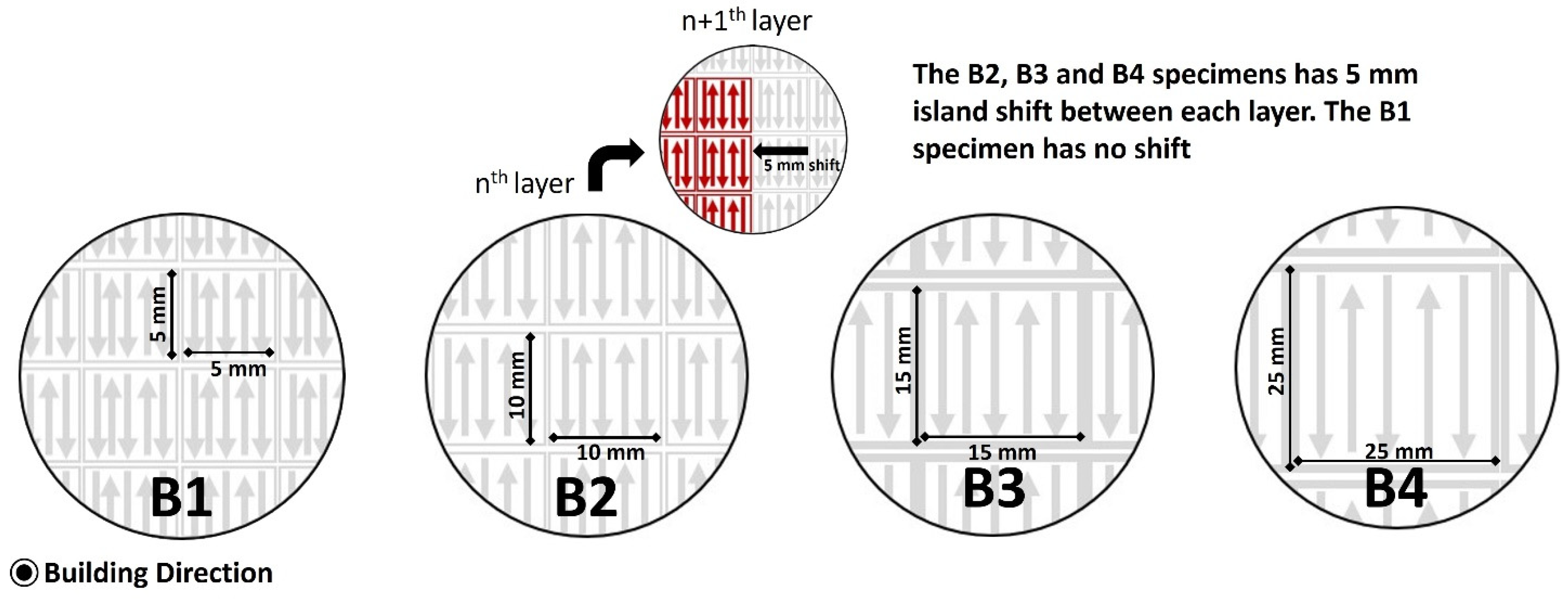
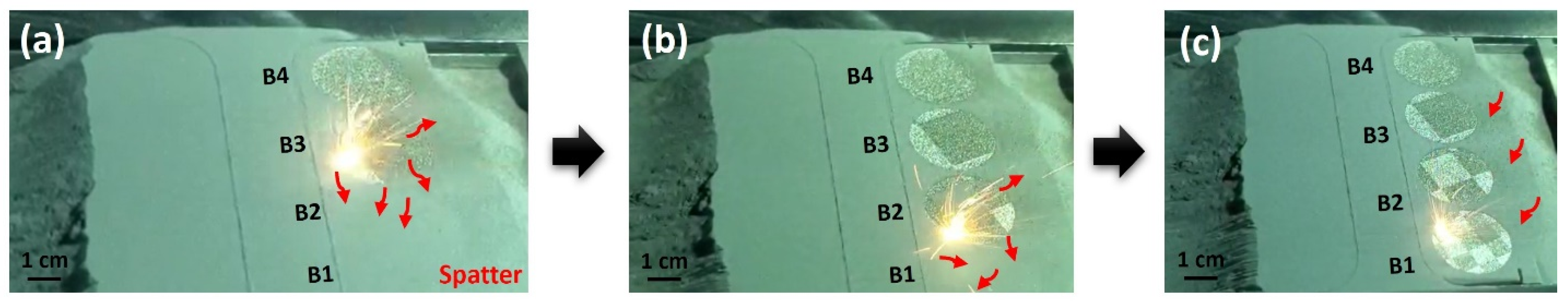
2.1. Materials and Laser—Powder Bed Fusion

Argon gas-atomized commercial 316 L stainless steel (316 L) feedstock with 63 μm maximum particle size was purchased from EOS, Norwell, MA, USA. The chemical composition of commercial 316 L feedstock is given in Table 1. The laser–powder bed fusion (LPBF) process was performed using a modified concept M100R with a 100 W Nd: YAG fiber laser at ∼1060 nm wavelength and 40 µm spot size. The laser printing parameters selected for the LPBF process are provided in Table 2. LPBF specimens were printed following 5 × 5 mm, 10 × 10 mm, 15 × 15 mm, and 25 × 25 mm island sizes and termed as B1, B2, B3, and B4, respectively. A 5 mm shift was introduced between each layer for B2, B3, and B4, whereas the B1 specimen had no shift, as presented in Figure 1. The LPBF parameters were revised to improve the density, and a 5 × 5 mm island-size coupon was printed and termed as A, as presented in Table 2.

2.2. Characterization

Optical microscopy was conducted using the Keyence Vkx1100 confocal laser scanning microscope. Micro-focus X-ray computed tomography (XRCT) was performed using a Zeiss Xradia 510 Versa 3D with 30–160 kV and 10 W maximum power. The porosity percentage for specimens B1–B4 was determined through XRCT analysis, while for sample A, it was measured from two-dimensional micrographs using binary thresholding. The density of the specimen was evaluated following Archimedes’ Principle. The LPBF specimens were ground using 1200-grid SiC sandpaper, followed by fine polishing with 0.05 µm colloidal silica suspension. Polished specimens were electro-etched in 10% oxalic acid at 15 V for 60 s (as per the ASTM A262 practice A).

2.3. Electrochemical Testing

Cyclic potentiodynamic polarization (CPP) of the LPBF specimens was conducted in 3.5 wt.% or 0.6 M NaCl electrolyte at room temperature (RT) and 35 °C on the specimens metallographically prepared using 1200-grit SiC. A three-electrode flat cell with a saturated calomel was used as a reference electrode (SCE) and a platinum mesh was used as a counter electrode (CE) for electrochemical testing. The CPP tests were initiated at 200 mV below open circuit potential (OCP). Then, the forward scan was dismissed, and a reverse scan was commenced when either 1.5 VSCE potential or 100 µA/cm2 current density was reached. A scan rate of 1mV/s was followed during the forward and reverse scans. The specimens were stabilized in testing electrolyte for 1 h, and the open circuit potential was recorded before the CPP test. The breakdown potential (Eb) and repassivation potential (Erep) were determined from the CPP curves, which were used to compare the corrosion performance of the tested specimens.

2.4. Microhardness

The Vickers microhardness test was conducted using the Mitutoyo Hardness machine on the B1, B2, B3, and B4 specimens, metallographically prepared using 1200-grit SiC. A load of 200 g and a dwell time of 15 s were followed during the test. The local hardness was noted after an average of 10 data points were taken for each specimen.

3. Results and Discussion

The laser powder bed fusion (LPBF) of 316 L stainless steel feedstock was performed multiple times following the same LPBF parameters, including laser power, laser scanning speed, layer thickness, hatch spacing, and island strategy, but with different island sizes and a 5 mm shift between each layer for each experimental specimen, as presented in Figure 1 and Table 2. Cylindrical specimens with 5 mm height and 20 mm diameter dimensions were printed. LPBF-316 L with different island sizes (5 × 5, 10 × 10, 15 × 15 and 25 × 25 mm) were termed as B1, B2, B3 and B4, respectively (Figure 1). In LPBF, the adjustment of island size, representative of laser-fused regions during the printing process, assumes significance in the modulation of solidification kinetics. Smaller islands correspond to expedited solidification, thereby influencing global cooling rates and, consequently, the spatial distribution of residual stresses within the fabricated component. Conversely, larger islands may engender slower cooling rates by retaining more thermal energy, potentially accentuating residual stresses owing to non-uniform thermal contraction. The optimization of island size necessitates a balance, as excessively small islands may compromise material integrity and interlayer adhesion.

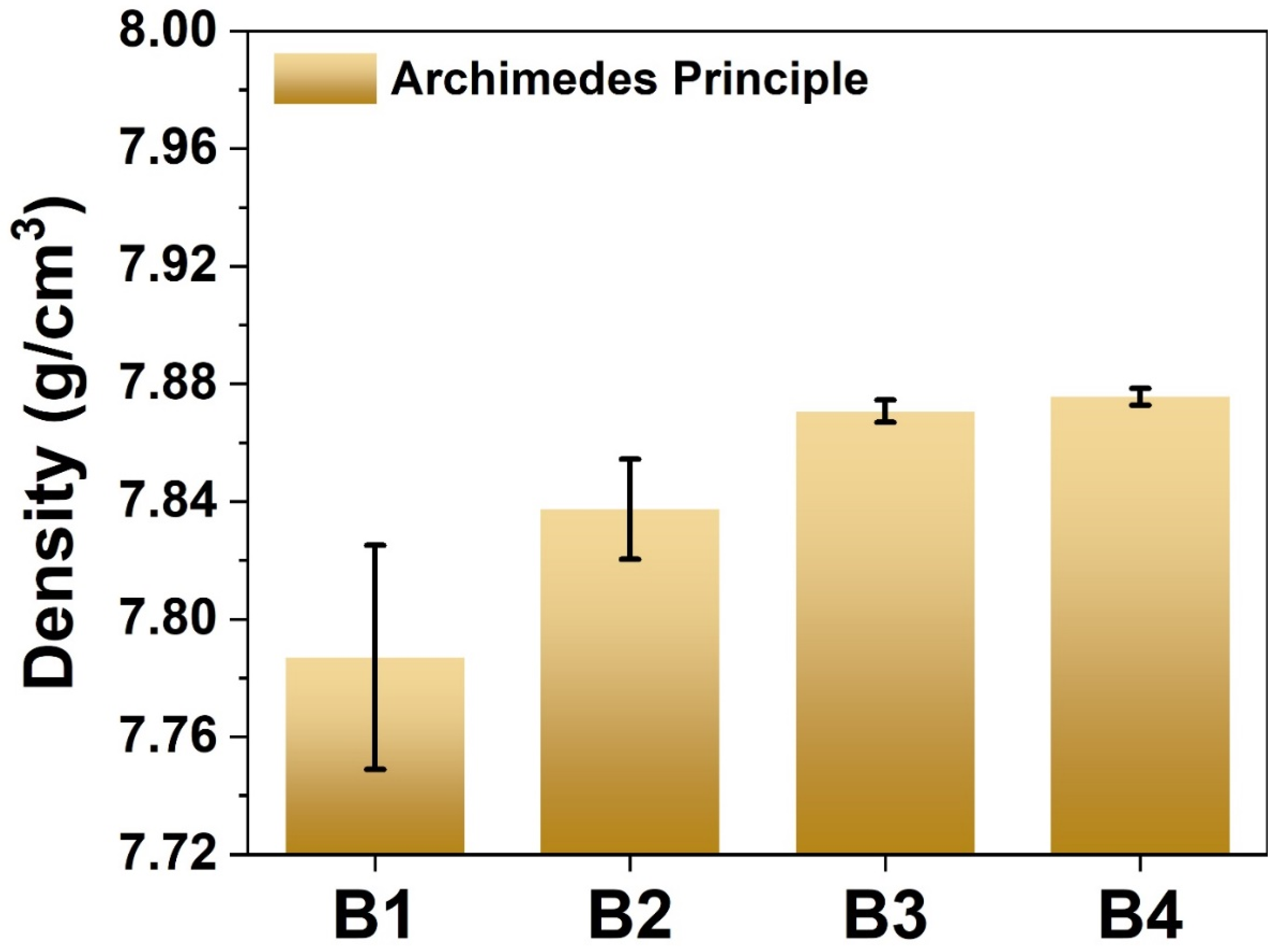
3.1. Density of LPBF Specimens

The densities of the B1, B2, B3, and B4 specimens, measured following Archimedes’ principle, are presented in Figure 2. Although all the LPBF specimens exhibited high density, an increasing trend in density with increased island size was observed. X-ray computed tomography scans were conducted on a single island for each of the B1, B2, B3, and B4 specimens to investigate the porosity percentage. The images in Figure 3a–d reveal the slice inside a single B1, B2, B3, and B4 island, respectively. The XRCT scans showed a decrease in porosity with increased island size, i.e., B1—2.85%, B2—1.44%, B3—1.43%, and B4—0.86%, which is in accordance with density measurements.
Figure 4 represents the images of B1, B2, B3, and B4 specimens taken during the LPBF process. As observed in Figure 4, the order of laser melting is B4 > B3 > B2 > B1. During the LPBF process, the phenomenon where powder particles are ejected and scattered around the build area is called spatter. Spatter can be of different types based on the formation mechanisms mentioned in the introduction; these types include solid spatter, metallic jet spatter, powder agglomeration spatter, entrainment melting spatter, and defect induced spatter [44,45,46]. As illustrated in Figure 4a–c, during the printing of B4, the resulting spatter was deposited on the powder beds of B3, B2, and B1, whereas the spatter generated during B3 printing was deposited on the powder beds of B2 and B1. Similarly, during B2 printing, the generated spatter was deposited on the powder bed of B1. Lastly, B1 was printed. This sequence of events revealed that the highest spatter deposition occurred in B1, while the lowest deposition was observed in B4. The deposited spatter can create quick fusing with the surrounding powder particles, causing pockets of trapped gas and uneven or incomplete melting, resulting in voids or gaps. Spatter can also reduce the bonding between layers, causing lack-of-fusion pores during LPBF melting. Spatter can also provide pathways for the development or growth of pores or voids, leading to higher porosity. Collectively, these phenomena can all cause high porosity in LPBF specimens. Moreover, spatter can also create irregularities and surface imperfections during LPBF printing, resulting in a poor surface finish. Therefore, less spatter deposition on the B4 powder bed favored higher density; in contrast, high spatter influence reduced the B1 specimen density.

3.2. Microstructure of LPBF Specimens

The microstructures revealed after etching the cross-sections of the B1, B2, B3, and B4 specimens are presented in Figure 5a–d, respectively. All of the LPBF specimens exhibited melt pool and melt pool boundaries. All of the LPBF specimens with different island sizes showed decent overlap between the built layers, indicating that island size may not have any influence on microstructure, due to complete melting between layers and tracks. The B1 specimen exhibited a high density of lack-of-fusion pores, particularly along the melt pool boundaries. The density of the lack-of-fusion pores was reduced with increased island size. All of the LPBF specimens exhibited sub-grain or cellular network structures viewed as equiaxed and columnar cellular structures [4,16], as presented in the high magnification micrographs of Figure 5. Figure 5e illustrates the histogram of melt pool depth (MPD) and melt pool width (MPW) of B1, B2, B3, and B4. All of the LPBF specimens exhibited similar melt pool dimensions, i.e., ~30–40 µm MPD and ~60–65 µm MPW. Additionally, the cell diameter size of B1, B2, B3, and B4 was <2 µm. Overall, it was observed that island size had no influence on melt pool dimensions or cell dimensions.

3.3. Properties of LPBF Specimens

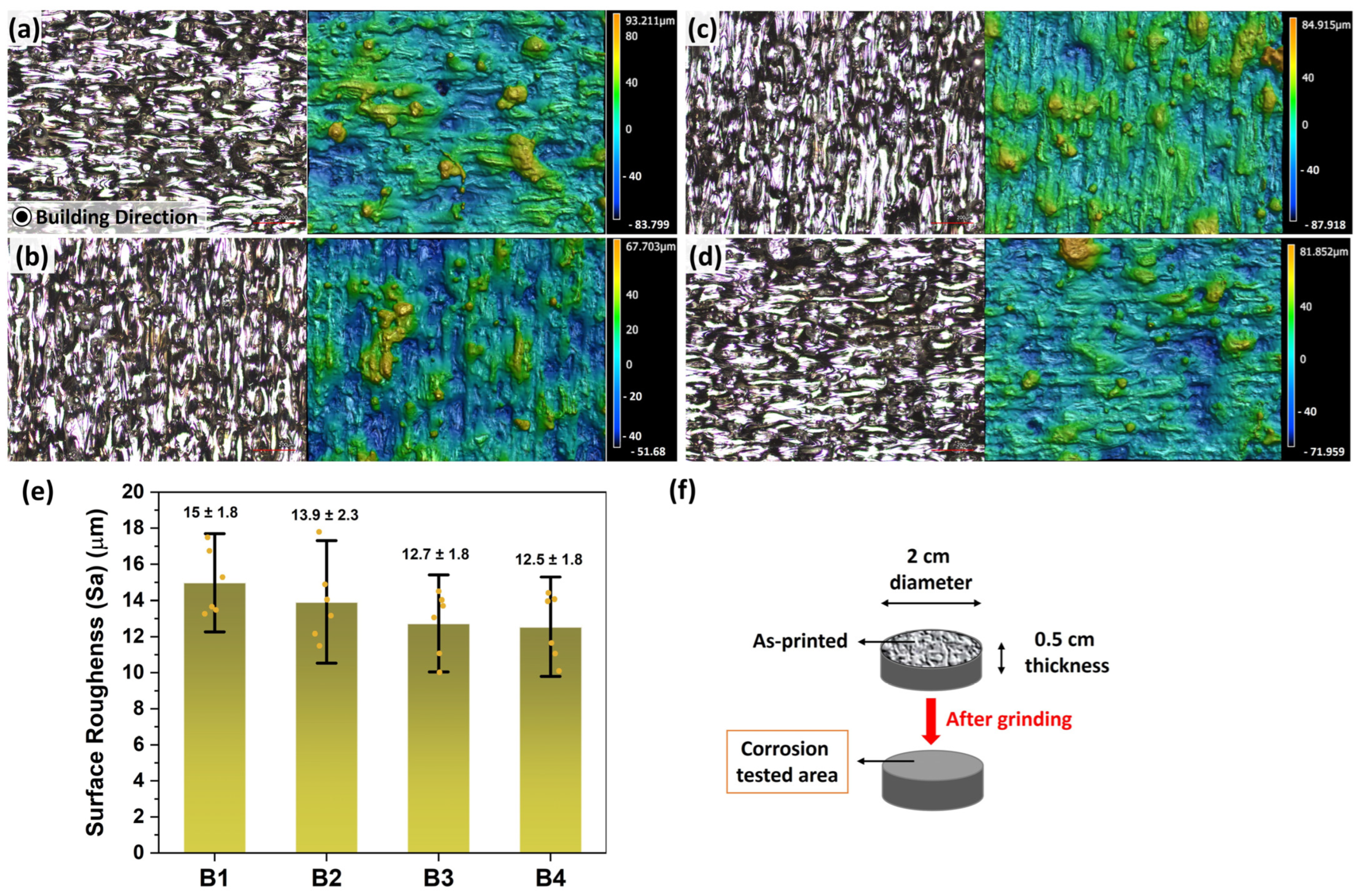
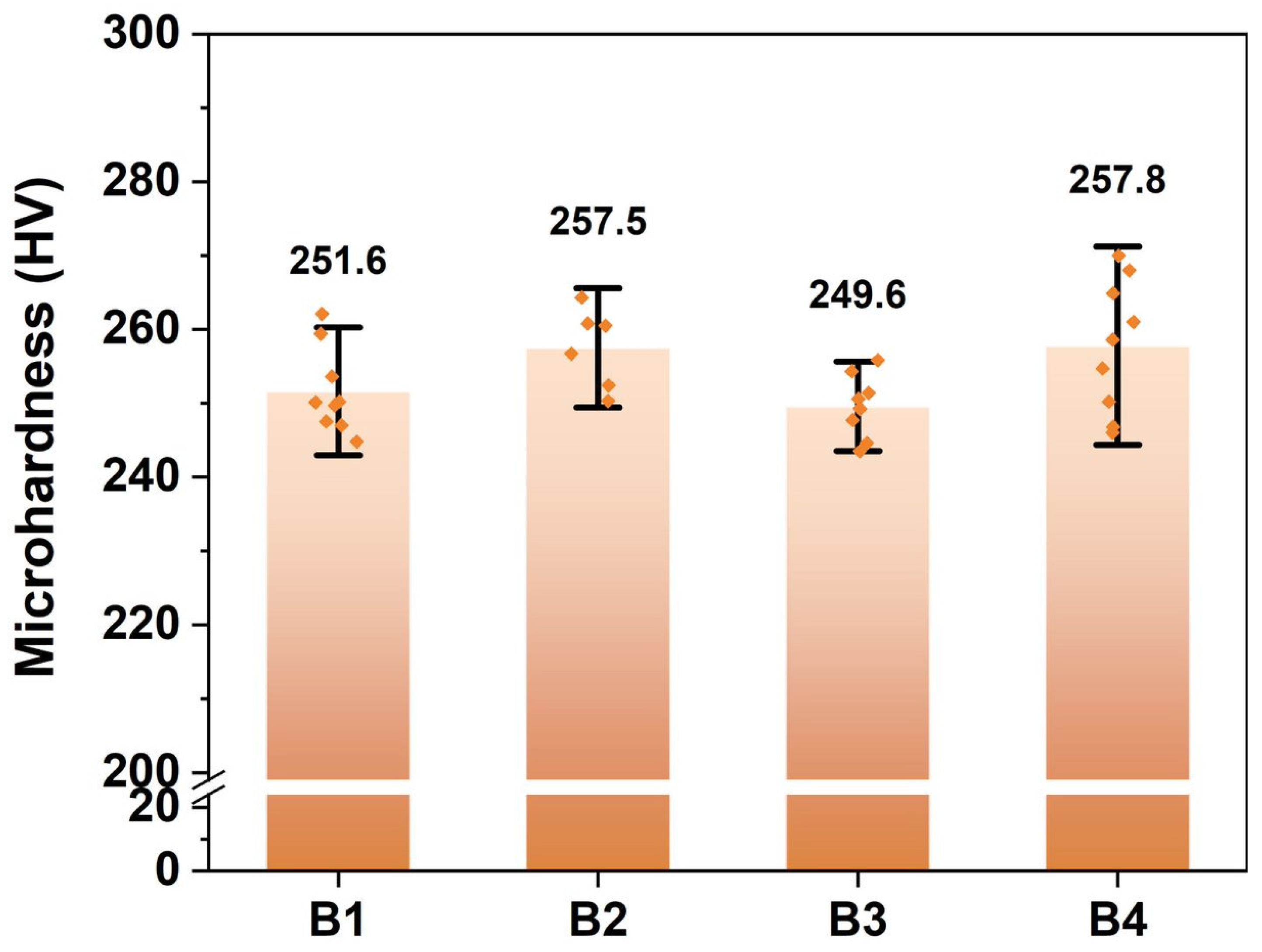
3.3.1. Surface Roughness and Microhardness

The surface roughness values of the B1, B2, B3, and B4 specimens, measured using surface profilometry, are presented in Figure 6a–d, respectively. The surface roughness of the LPBF specimens was between ~(10–20) µm and followed a decreasing trend in surface roughness with an increase in island size, i.e., B1 > B2 > B3 > B4 (Figure 6e). However, all of the LPBF specimens exhibited the balling phenomenon, which is caused due to a slightly thicker powder layer and insufficient laser energy to melt the thick powder layer completely. As discussed in Section 3.1, the order of surface finish can be correlated to the spatter deposition of the LPBF specimens (Figure 4). A high spatter deposition in the B1 powder bed caused poor surface finish, i.e., the deposited spatter favored the fusing of surrounding powder particles, creating imperfections and surface irregularities and, thus, poor surface finish. Similarly, due to the printing order, the B4 specimen experienced less spatter, resulting in a better surface finish.
The microhardness of the B1, B2, B3, and B4 specimens is given in Figure 7. The microhardness values of the LPBF specimens were between ~(240–270) HV. All of the LPBF specimens exhibited similar average microhardness, and no trend in the microhardness of different LPBF specimens was observed.

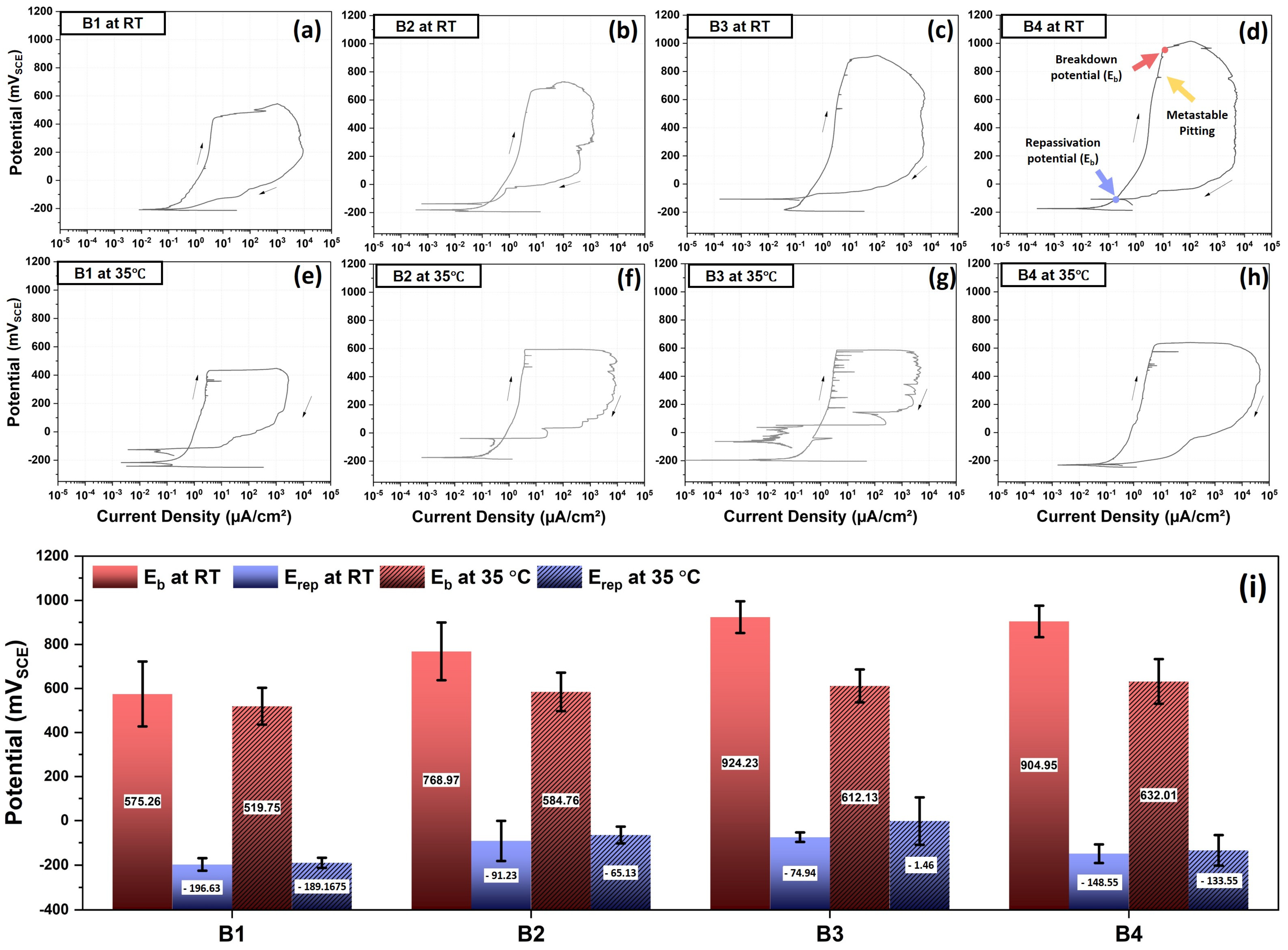
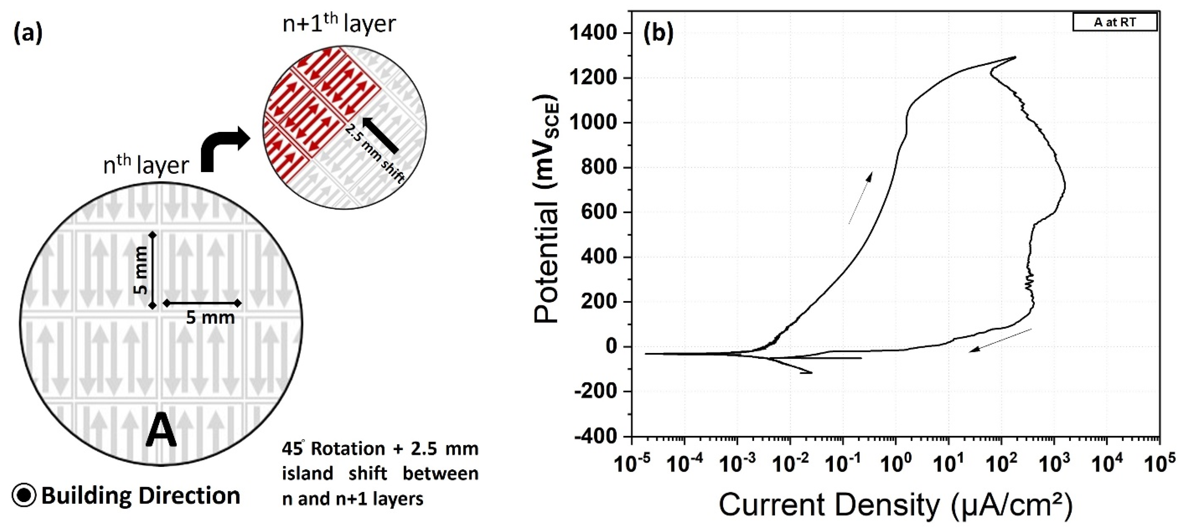
3.3.2. Corrosion Performance

The cyclic potentiodynamic curves of B1, B2, B3, and B4 specimens conducted at room temperature (RT) and 35 °C are presented in Figure 8a–d and Figure 8e–h, respectively. At RT and 35 °C, the open circuit potential (OCP) was around ~−200 mVSCE, and as the potential increased, metastable pitting was observed in all the LPBF specimens. The breakdown potentials (Eb) and repassivation potential (Erep) of B1–B4 specimens at RT and 35 °C are presented in Figure 8i. The Eb at RT exhibited an increasing trend with an increase in island size, i.e., the Eb values for B1, B2, B3, and B4 were 575 ± 147, 768 ± 131, 924 ± 71, and 904 ± 71 mVSCE, respectively. At 35 °C, minor enhancements in the Eb of the B1–B4 specimens were observed with an increase in island size, i.e., 540 ± 94, 584 ± 87, 612 ± 74, and 632 ± 101 mVSCE, respectively. At both RT and 35 °C, all of the LPBF specimens exhibited a repassivation potential (Erep) around ~−250 to 0 mVSCE, i.e., neither island size nor the testing temperature influenced the Erep of the LPBF specimens. However, close observation revealed a correlation between Eb and Erep potentials, i.e., LPBF specimen tests at RT showed higher Eb and lower Erep potentials, whereas at 35 °C, they exhibited lower Eb and higher Erep potentials. The lower Erep potential could be attributed to the occurrence of crevice corrosion at higher polarization potentials, i.e., as the LPBF specimens were subjected to polarization at higher potentials (~1 mVSCE), a high probability of crevice corrosion was observed around the boundaries of the exposed surface to the electrolyte. Later, during the reverse scan, the crevice corrosion was further continued, as revealed by high current densities (~104 µA/cm2), and consequently, the repassivation tendency might have drastically reduced. However, this phenomenon was not observed in the B1 specimen due to its high porosity, which favored early passive film breakdown and poor repassivation tendency. Overall, the B4 specimen exhibited higher corrosion resistance, which could be attributed to the improved density. The specimen with a larger island size and the 5 mm shift tailored the layers well, resulting in the B4 specimen having high density; therefore, enhanced corrosion resistance was observed.
A pre-existing pore or porosity profoundly influences pitting kinetics by creating localized galvanic cells, increasing anodic surface area, fostering concentration cells, and affecting oxygen diffusion. These pores act as anodic sites, accelerating corrosion through galvanic coupling while simultaneously trapping electrolytes and corrosive substances, forming concentration cells that intensify corrosion at specific locations. The expanded anodic surface area enhances overall anodic reaction rates, and restricted oxygen diffusion contributes to the breakdown of protective oxide films, promoting the initiation and growth of pits. In essence, the electrochemical impact of pores on pitting kinetics is multifaceted, creating favorable conditions for accelerated localized corrosion processes. This explains the high probability of early breakdown in B1 specimens compared to B4 specimens. Additionally, In LPBF 316 L, due to specific microstructural characteristics, a peculiar corrosion morphology was often reported [4,15,16], i.e., the cellular structure was revealed with corroded cells and intact cell boundaries. A similar corrosion morphology can be expected for LPBF-316 L tested in 0.6 M NaCl at RT. Researchers [4,15,16] have reported that the solute segregation of Cr, Ni, and Mo along the cellular boundaries might have delayed corrosion kinetics at these sites. However, the post corrosion characteristics of LPBF-316 L tested in 0.6 NaCl at 35 °C might differ slightly. Understanding the morphology of LPBF-316 L corrosion tested under high temperatures could be a potential area of future exploration. This research explores the influence of island size and spatter on microstructure and corrosion properties. Investigating the mechanisms of how spatter creates porosity, how island size and shift between the layers impacts the texture and grain size, and why a significant difference in corrosion resistance is not observed when tested at 35 °C could be worth exploring as part of future work related to this research.

3.4. Enhanced Corrosion Resistance with Revised LPBF Parameters

The presence of porosity has been linked to variations in corrosion resistance observed between specimens B1–B4. Modifying and optimizing the LPBF parameters is expected to decrease porosity and increase the density of LPBF-316 L. Introducing rotation between the LPBF layers has become a popular approach for enhancing the density and properties of the specimen [51] by facilitating more uniform powder distribution and fusion. Substrate rotation assists in evenly spreading the powder layers, minimizing voids and gaps between particles, thereby promoting denser packing. Moreover, rotation aids in revitalizing the powder bed, ensuring consistent powder properties, and reducing the likelihood of porosity formation due to variations in powder characteristics. Consequently, in the present study, the laser powder bed fusion parameters were adjusted, and a 45-degree rotation, along with a 2.5 mm island shift, was implemented between the LPBF layers of specimen A, as depicted in Figure 9a. These revised LPBF parameters led to enhanced density in specimen A (7.91 g/cm3) and reduced its porosity (0.338 ± 0.0325%). The corresponding cyclic potentiodynamic polarization graph of specimen A, tested in 0.6 M NaCl at room temperature, is shown in Figure 9b. The observed corrosion characteristics were significantly superior to those of specimens B1–B4, with a breakdown potential of 1059 ± 10 mVSCE, representing an approximately 85% and 17% improvement compared to B1 and B4, respectively. The repassivation potential of specimen A was −60 ± 7 mVSCE, which was again significantly higher than that of specimens B1–B4. Additionally, no metastable pits were observed in specimen A. The reduced porosity (improved density) was presumed to be a significant contributing factor to the enhancement of corrosion resistance, as elucidated from the previous analysis and assessment.

4. Conclusions

The laser powder bed fusion process was utilized to fabricate 316 L stainless steel alloy specimens with varying island sizes (5 × 5, 10 × 10, 15 × 15, and 25 × 25 mm). Throughout the LPBF process, all specimens experienced spatter, prompting an investigation into the influence of spatter, with differing island sizes, on density, microstructure, surface roughness, microhardness, and corrosion performance. Increasing the island size resulted in improved density and reduced surface roughness in the specimens, attributed to reduced spatter and porosity. Microhardness remained consistent across all LPBF specimens. Polarization tests were conducted at room temperature (RT) and at 35 °C, demonstrating enhanced corrosion resistance in specimens with larger island sizes due to fewer manufacturing defects such as lack-of-fusion pores and gas porosity. This study underscores the importance of considering spatter effects when optimizing LPBF processing parameters. Subsequent revisions to the printing parameters further significantly enhanced the density and corrosion resistance of LPBF-316 L. The research highlights the potential for minor adjustments in specific processing parameters to significantly impact the resulting alloy’s properties.

Author Contributions

Conceptualization, V.B.V., S.S., T.H. and R.K.G.; methodology, V.B.V. and S.S.; validation, V.B.V. and S.S.; formal analysis, V.B.V., T.S., J.S., S.S. and R.B.; investigation, V.B.V. and S.S.; resources, T.H.; data curation, V.B.V., T.S., J.S., S.S. and R.B.; writing—original draft preparation, V.B.V.; writing—review and editing, S.S., R.B., T.H. and R.K.G.; supervision, T.H. and R.K.G.; All authors have read and agreed to the published version of the manuscript.

Funding

This research was funded and supported by the Office of Naval Research with David Shifler as the program officer under the contracts ONR: N00014-21-1-2489.

Data Availability Statement

The raw data supporting the conclusions of this article will be made available by the authors on request.

Acknowledgments

R.K.G. acknowledges the Office of Naval Research for funding under the contracts ONR: N00014-21-1-2489 with David Shifler as the program officer. The authors acknowledge the Analytical Instrumentation Facility (AIF) at North Carolina State University, supported by the State of North Carolina and the National Science Foundation (award number ECCS-2025064). The AIF is a member of the North Carolina Research Triangle Nanotechnology Network (RTNN), a site in the National Nanotechnology Coordinated Infrastructure (NNCI).

Conflicts of Interest

The authors declare no conflict of interest.

References

  1. Rajaguru, K.; Karthikeyan, T.; Vijayan, V. Additive manufacturing—State of art. Mater. Today Proc. 2020, 21, 628–633. [Google Scholar] [CrossRef]
  2. Frazier, W.E. Metal Additive Manufacturing: A Review. J. Mater. Eng. Perform. 2014, 23, 1917–1928. [Google Scholar] [CrossRef]
  3. Singh, R.; Gupta, A.; Tripathi, O.; Srivastava, S.; Singh, B.; Awasthi, A.; Rajput, S.; Sonia, P.; Singhal, P.; Saxena, K.K. Powder bed fusion process in additive manufacturing: An overview. Mater. Today Proc. 2020, 26, 3058–3070. [Google Scholar] [CrossRef]
  4. Vukkum, V.; Gupta, R. Review on corrosion performance of laser powder-bed fusion printed 316L stainless steel: Effect of processing parameters, manufacturing defects, post-processing, feedstock, and microstructure. Mater. Des. 2022, 221, 110874. [Google Scholar] [CrossRef]
  5. Tofail, S.A.M.; Koumoulos, E.P.; Bandyopadhyay, A.; Bose, S.; O’Donoghue, L.; Charitidis, C. Additive manufacturing: Scientific and technological challenges, market uptake and opportunities. Mater. Today 2018, 21, 22–37. [Google Scholar] [CrossRef]
  6. Bajaj, P.; Hariharan, A.; Kini, A.; Kürnsteiner, P.; Raabe, D.; Jägle, E.A. Steels in additive manufacturing: A review of their microstructure and properties. Mater. Sci. Eng. A 2020, 772, 138633. [Google Scholar] [CrossRef]
  7. Vukkum, V.B.; Ray, T.; Karmakar, A.; Das, S. Microstructure–Texture–Mechanical Property Correlation in Laser-Welded Dual-Phase and Interstitial-Free Steel Blanks. J. Mater. Eng. Perform. 2023, 33, 318–329. [Google Scholar] [CrossRef]
  8. Anatoliy, P.; Vadim, S. Metal Powder Additive Manufacturing. In New Trends 3D Print; InTech: Houston, TX, USA, 2016. [Google Scholar] [CrossRef]
  9. DebRoy, T.; Wei, H.L.; Zuback, J.S.; Mukherjee, T.; Elmer, J.W.; Milewski, J.O.; Beese, A.M.; Wilson-Heid, A.; De, A.; Zhang, W. Additive manufacturing of metallic components—Process, structure and properties. Prog. Mater. Sci. 2018, 92, 112–224. [Google Scholar] [CrossRef]
  10. Gu, D.D.; Meiners, W.; Wissenbach, K.; Poprawe, R. Laser additive manufacturing of metallic components: Materials, processes and mechanisms. Int. Mater. Rev. 2012, 57, 133–164. [Google Scholar] [CrossRef]
  11. Pidge, P.A.; Kumar, H. Additive manufacturing: A review on 3 D printing of metals and study of residual stress, buckling load capacity of strut members. Mater. Today Proc. 2019, 21, 1689–1694. [Google Scholar] [CrossRef]
  12. Ozdemir, F.; Christudasjustus, J.; Vukkum, V.B.; Okuyucu, H.; Gupta, R.K. Need of an Inert Atmosphere for High-Energy Ball Milling of Al Alloys. J. Mater. Eng. Perform. 2022, 32, 3007–3013. [Google Scholar] [CrossRef]
  13. Vukkum, V.B.; Christudasjustus, J.; Ansell, T.Y.; Nieto, A.; Gupta, R.K. Influence of carbon nanotubes on microstructure and corrosion performance of additively manufactured 316L stainless steel. Corros. Sci. 2023, 224, 111494. [Google Scholar] [CrossRef]
  14. Vukkum, V.B.; A Darwish, A.; Christudasjustus, J.; Storck, S.; Gupta, R.K. Corrosion Performance of Additively Manufactured 316L Stainless Steel Produced By Feedstock Modification. ECS Meet. Abstr. 2022, MA2022-01, 1013. [Google Scholar] [CrossRef]
  15. Vukkum, V.; Ozdemir, F.; Storck, S.; Gupta, R. Corrosion performance of feedstock modified—Additively manufactured stainless steel. Corros. Sci. 2022, 209, 110724. [Google Scholar] [CrossRef]
  16. Vukkum, V.B.; Christudasjustus, J.; Darwish, A.A.; Storck, S.M.; Gupta, R.K. Enhanced corrosion resistance of additively manufactured stainless steel by modification of feedstock. npj Mater. Degrad. 2022, 6, 2. [Google Scholar] [CrossRef]
  17. Santa-Aho, S.; Kiviluoma, M.; Jokiaho, T.; Gundgire, T.; Honkanen, M.; Lindgren, M.; Vippola, M. Additive Manufactured 316L Stainless-Steel Samples: Microstructure, Residual Stress and Corrosion Characteristics after Post-Processing. Metals 2021, 11, 182. [Google Scholar] [CrossRef]
  18. Chen, L.; Richter, B.; Zhang, X.; Ren, X.; Pfefferkorn, F.E. Modification of surface characteristics and electrochemical corrosion behavior of laser powder bed fused stainless-steel 316L after laser polishing. Addit. Manuf. 2020, 32, 101013. [Google Scholar] [CrossRef]
  19. Nieto, A.; Vukkum, V.B.; Jalagam, P.; Nema, K.; Budan, J.; Gupta, R.K.; Ansell, T.Y. 3D printed carbon nanotube reinforced stainless steel via selective laser melting. MRS Commun. 2022, 12, 578–584. [Google Scholar] [CrossRef]
  20. Vukkum, V.B.; Delvecchio, E.; Christudasjustus, J.; Storck, S.; Gupta, R.K. Intergranular Corrosion of Feedstock Modified—Additively Manufactured Stainless Steel After Sensitization. Corrosion 2023, 79, 624–636. [Google Scholar] [CrossRef]
  21. Cherry, J.A.; Davies, H.M.; Mehmood, S.; Lavery, N.P.; Brown, S.G.R.; Sienz, J. Investigation into the effect of process parameters on microstructural and physical properties of 316L stainless steel parts by selective laser melting. Int. J. Adv. Manuf. Technol. 2014, 76, 869–879. [Google Scholar] [CrossRef]
  22. Minasyan, T.; Hussainova, I. Laser Powder-Bed Fusion of Ceramic Particulate Reinforced Aluminum Alloys: A Review. Materials 2022, 15, 2467. [Google Scholar] [CrossRef]
  23. Jadhav, S.D.; Goossens, L.R.; Kinds, Y.; Van Hooreweder, B.; Vanmeensel, K. Laser-based powder bed fusion additive manufacturing of pure copper. Addit. Manuf. 2021, 42, 101990. [Google Scholar] [CrossRef]
  24. Godec, M.; Donik, Č.; Kocijan, A.; Podgornik, B.; Balantič, D.S. Effect of post-treated low-temperature plasma nitriding on the wear and corrosion resistance of 316L stainless steel manufactured by laser powder-bed fusion. Addit. Manuf. 2020, 32, 101000. [Google Scholar] [CrossRef]
  25. Qu, S.; Ding, J.; Fu, J.; Fu, M.; Zhang, B.; Song, X. High-precision laser powder bed fusion processing of pure copper. Addit. Manuf. 2021, 48, 102417. [Google Scholar] [CrossRef]
  26. Depboylu, F.N.; Yasa, E.; Poyraz, Ö.; Minguella-Canela, J.; Korkusuz, F.; López, M.A.d.L.S. Titanium based bone implants production using laser powder bed fusion technology. J. Mater. Res. Technol. 2022, 17, 1408–1426. [Google Scholar] [CrossRef]
  27. Liu, J.; Wen, P. Metal vaporization and its influence during laser powder bed fusion process. Mater. Des. 2022, 215, 110505. [Google Scholar] [CrossRef]
  28. Walker, J.; Middendorf, J.R.; Lesko, C.C.; Gockel, J. Multi-material laser powder bed fusion additive manufacturing in 3-dimensions. Manuf. Lett. 2022, 31, 74–77. [Google Scholar] [CrossRef]
  29. Li, R.; Liu, J.; Shi, Y.; Du, M.; Xie, Z. 316L Stainless Steel with Gradient Porosity Fabricated by Selective Laser Melting. J. Mater. Eng. Perform. 2010, 19, 666–671. [Google Scholar] [CrossRef]
  30. Sun, Z.J.; Tan, X.P.; Tor, S.B.; Yeong, W.Y. Selective laser melting of stainless steel 316L with low porosity and high build rates. Mater. Des. 2016, 104, 197–204. [Google Scholar] [CrossRef]
  31. Wang, G.; Liu, Q.; Rao, H.; Liu, H.; Qiu, C. Influence of porosity and microstructure on mechanical and corrosion properties of a selectively laser melted stainless steel. J. Alloys Compd. 2020, 831, 154815. [Google Scholar] [CrossRef]
  32. Sola, A.; Nouri, A. Microstructural porosity in additive manufacturing: The formation and detection of pores in metal parts fabricated by powder bed fusion. J. Adv. Manuf. Process. 2019, 1, e10021. [Google Scholar] [CrossRef]
  33. Liu, M.; Zhu, J.-N.; Popovich, V.; Borisov, E.; Mol, J.; Gonzalez-Garcia, Y. Passive film formation and corrosion resistance of laser-powder bed fusion fabricated NiTi shape memory alloys. J. Mater. Res. Technol. 2023, 23, 2991–3006. [Google Scholar] [CrossRef]
  34. Oliveira, J.P.; LaLonde, A.D.; Ma, J. Processing parameters in laser powder bed fusion metal additive manufacturing. Mater. Des. 2020, 193, 108762. [Google Scholar] [CrossRef]
  35. Tucho, W.M.; Lysne, V.H.; Austbø, H.; Sjolyst-Kverneland, A.; Hansen, V. Investigation of effects of process parameters on microstructure and hardness of SLM manufactured SS316L. J. Alloys Compd. 2018, 740, 910–925. [Google Scholar] [CrossRef]
  36. Wang, C.; Tan, X.; Liu, E.; Tor, S.B. Process parameter optimization and mechanical properties for additively manufactured stainless steel 316L parts by selective electron beam melting. Mater. Des. 2018, 147, 157–166. [Google Scholar] [CrossRef]
  37. Kurzynowski, T.; Gruber, K.; Stopyra, W.; Kuźnicka, B.; Chlebus, E. Correlation between process parameters, microstructure and properties of 316 L stainless steel processed by selective laser melting. Mater. Sci. Eng. A 2018, 718, 64–73. [Google Scholar] [CrossRef]
  38. Fayazfar, H.; Salarian, M.; Rogalsky, A.; Sarker, D.; Russo, P.; Paserin, V.; Toyserkani, E. A critical review of powder-based additive manufacturing of ferrous alloys: Process parameters, microstructure and mechanical properties. Mater. Des. 2018, 144, 98–128. [Google Scholar] [CrossRef]
  39. Eliasu, A.; Czekanski, A.; Boakye-Yiadom, S. Effect of laser powder bed fusion parameters on the microstructural evolution and hardness of 316L stainless steel. Int. J. Adv. Manuf. Technol. 2021, 113, 2651–2669. [Google Scholar] [CrossRef]
  40. Dursun, G.; Ibekwe, S.; Li, G.; Mensah, P.; Joshi, G.; Jerro, D. Influence of laser processing parameters on the surface characteristics of 316L stainless steel manufactured by selective laser melting. Mater. Today Proc. 2020, 26, 387–393. [Google Scholar] [CrossRef]
  41. Liverani, E.; Toschi, S.; Ceschini, L.; Fortunato, A. Effect of selective laser melting (SLM) process parameters on microstructure and mechanical properties of 316L austenitic stainless steel. J. Am. Acad. Dermatol. 2017, 249, 255–263. [Google Scholar] [CrossRef]
  42. Ni, X.; Kong, D.; Wu, W.; Zhang, L.; Dong, C.; He, B.; Lu, L.; Wu, K.; Zhu, D. Corrosion Behavior of 316L Stainless Steel Fabricated by Selective Laser Melting Under Different Scanning Speeds. J. Mater. Eng. Perform. 2018, 27, 3667–3677. [Google Scholar] [CrossRef]
  43. Puichaud, A.-H.; Flament, C.; Chniouel, A.; Lomello, F.; Rouesne, E.; Giroux, P.-F.; Maskrot, H.; Schuster, F.; Béchade, J.-L. Microstructure and mechanical properties relationship of additively manufactured 316L stainless steel by selective laser melting. EPJ Nucl. Sci. Technol. 2019, 5, 23. [Google Scholar] [CrossRef]
  44. Liu, Y.; Yang, Y.; Mai, S.; Wang, D.; Song, C. Investigation into spatter behavior during selective laser melting of AISI 316L stainless steel powder. Mater. Des. 2015, 87, 797–806. [Google Scholar] [CrossRef]
  45. Khairallah, S.A.; Anderson, A.T.; Rubenchik, A.; King, W.E. Laser powder-bed fusion additive manufacturing: Physics of complex melt flow and formation mechanisms of pores, spatter, and denudation zones. Acta Mater. 2016, 108, 36–45. [Google Scholar] [CrossRef]
  46. Simonelli, M.; Tuck, C.; Aboulkhair, N.T.; Maskery, I.; Ashcroft, I.; Wildman, R.D.; Hague, R. A Study on the Laser Spatter and the Oxidation Reactions During Selective Laser Melting of 316L Stainless Steel, Al-Si10-Mg, and Ti-6Al-4V. Met. Mater. Trans. A 2015, 46, 3842–3851. [Google Scholar] [CrossRef]
  47. Ahmed, N.; Barsoum, I.; Haidemenopoulos, G.; Abu Al-Rub, R. Process parameter selection and optimization of laser powder bed fusion for 316L stainless steel: A review. J. Manuf. Process. 2022, 75, 415–434. [Google Scholar] [CrossRef]
  48. Salman, O.; Brenne, F.; Niendorf, T.; Eckert, J.; Prashanth, K.; He, T.; Scudino, S. Impact of the scanning strategy on the mechanical behavior of 316L steel synthesized by selective laser melting. J. Manuf. Process. 2019, 45, 255–261. [Google Scholar] [CrossRef]
  49. Jia, H.; Sun, H.; Wang, H.; Wu, Y.; Wang, H. Scanning strategy in selective laser melting (SLM): A review. Int. J. Adv. Manuf. Technol. 2021, 113, 2413–2435. [Google Scholar] [CrossRef]
  50. Song, Y.; Sun, Q.; Guo, K.; Wang, X.; Liu, J.; Sun, J. Effect of scanning strategies on the microstructure and mechanical behavior of 316L stainless steel fabricated by selective laser melting. Mater. Sci. Eng. A 2020, 793, 139879. [Google Scholar] [CrossRef]
  51. Marattukalam, J.J.; Karlsson, D.; Pacheco, V.; Beran, P.; Wiklund, U.; Jansson, U.; Hjörvarsson, B.; Sahlberg, M. The effect of laser scanning strategies on texture, mechanical properties, and site-specific grain orientation in selective laser melted 316L SS. Mater. Des. 2020, 193, 108852. [Google Scholar] [CrossRef]
  52. Bian, P.; Shi, J.; Liu, Y.; Xie, Y. Influence of laser power and scanning strategy on residual stress distribution in additively manufactured 316L steel. Opt. Laser Technol. 2020, 132, 106477. [Google Scholar] [CrossRef]
  53. Lu, Y.; Wu, S.; Gan, Y.; Huang, T.; Yang, C.; Junjie, L.; Lin, J. Study on the microstructure, mechanical property and residual stress of SLM Inconel-718 alloy manufactured by differing island scanning strategy. Opt. Laser Technol. 2015, 75, 197–206. [Google Scholar] [CrossRef]
  54. Larimian, T.; Kannan, M.; Grzesiak, D.; AlMangour, B.; Borkar, T. Effect of energy density and scanning strategy on densification, microstructure and mechanical properties of 316L stainless steel processed via selective laser melting. Mater. Sci. Eng. A 2020, 770, 138455. [Google Scholar] [CrossRef]
  55. Roirand, H.; Malard, B.; Hor, A.; Saintier, N. Effect of laser scan pattern in laser powder bed fusion process: The case of 316L stainless steel. Procedia Struct. Integr. 2021, 38, 149–158. [Google Scholar] [CrossRef]
  56. Wu, A.S.; Brown, D.W.; Kumar, M.; Gallegos, G.F.; King, W.E. An Experimental Investigation into Additive Manufacturing-Induced Residual Stresses in 316L Stainless Steel. Met. Mater. Trans. A 2014, 45, 6260–6270. [Google Scholar] [CrossRef]
  57. Zhang, H.; Vallabh, C.K.P.; Zhao, X. Influence of spattering on in-process layer surface roughness during laser powder bed fusion. J. Manuf. Process. 2023, 104, 289–306. [Google Scholar] [CrossRef]
  58. Young, Z.A.; Guo, Q.; Parab, N.D.; Zhao, C.; Qu, M.; Escano, L.I.; Fezzaa, K.; Everhart, W.; Sun, T.; Chen, L. Types of spatter and their features and formation mechanisms in laser powder bed fusion additive manufacturing process. Addit. Manuf. 2020, 36, 101438. [Google Scholar] [CrossRef]
  59. Wang, Y.; Guo, W.; Xie, Y.; Li, H.; Zeng, C.; Xu, M.; Zhang, H. In-situ monitoring plume, spattering behavior and revealing their relationship with melt flow in laser powder bed fusion of nickel-based superalloy. J. Mater. Sci. Technol. 2024, 177, 44–58. [Google Scholar] [CrossRef]
  60. Pinto, F.; Filho, I.S.; Sandim, M.; Sandim, H. Defects in parts manufactured by selective laser melting caused by δ-ferrite in reused 316L steel powder feedstock. Addit. Manuf. 2020, 31, 100979. [Google Scholar] [CrossRef]
  61. Lu, C.; Zhang, R.; Wei, X.; Xiao, M.; Yin, Y.; Qu, Y.; Li, H.; Liu, P.; Qiu, X.; Guo, T. An investigation on the oxidation behavior of spatters generated during the laser powder bed fusion of 316L stainless steel. Appl. Surf. Sci. 2022, 586, 152796. [Google Scholar] [CrossRef]
Figure 1. Schematic representation of island scanning strategy with varying island sizes used for laser powder bed fusion. The gray arrow indicates the laser rastering within the island, and the black arrow represents the 5 mm shift introduced for B2, B3, and B4 specimens.
Crystals 14 00328 g001
Figure 2. Density of B1, B2, B3 and B4 specimens, evaluated following Archimedes principle.
Crystals 14 00328 g002
Figure 3. XRCT scan of a slice of a single island of (a) B1, (b) B2, (c) B3, and (d) B4 specimens, and corresponding evaluated porosity, respectively.
Crystals 14 00328 g003
Figure 4. (ac) The sequence of laser powder bed fusion printing of the B4, B3, B2, and B1 specimens. The red arrows indicate the possible direction of spatter flow during the laser powder bed fusion process.
Crystals 14 00328 g004
Figure 5. Low and high magnification optical micrographs of (a) B1, (b) B2, (c) B3, and (d) B4 specimens and their corresponding (e) melt pool dimensions, where MPD and MPW stand for melt pool depth and melt pool width, respectively.
Crystals 14 00328 g005
Figure 6. Surface profilometry micrographs presenting the as-printed surface of the (a) B1, (b) B2, (c) B3, and (d) B4 specimen and their corresponding (e) surface roughness. (f) Schematic representation of the specimens.
Crystals 14 00328 g006
Figure 7. Vickers microhardness conducted on ground surfaces of the B1, B2, B3, and B4 specimens.
Crystals 14 00328 g007
Figure 8. Cyclic potentiodynamic polarization of the B1, B2, B3, and B4 specimens was conducted at (ad) room temperature (RT) and (eh) 35 °C, respectively, in 3.5 wt% NaCl. (i) Bar graph presenting the breakdown potentials (Eb) and repassivation potentials (Erep) of corresponding graphs.
Crystals 14 00328 g008
Figure 9. (a) Schematic representation of island scanning strategy followed during laser powder bed fusion of specimen A, and (b) its corresponding cyclic potentiodynamic polarization conducted at room temperature (RT) in 0.6 M NaCl.
Crystals 14 00328 g009
Table 1. Chemical composition of commercial EOS 316 L stainless steel feedstock in wt.%.
ElementCrNiMoMnSiCNCuSPFe
Wt.%1813.572.661.560.260.0050.070.01<0.0050.012Balance
Table 2. Laser powder bed fusion printing parameters and respective porosity.
LPBF Specimens
B1B2B3B4A
Laser power90 W90 W90 W90 W90 W
Laser scanning speed1500 mm/s1500 mm/s1500 mm/s1500 mm/s1500 mm/s
Layer thickness0.015 mm0.015 mm0.015 mm0.015 mm0.015 mm
Hatch spacing0.08 mm0.08 mm0.08 mm0.08 mm0.08 mm
Laser scanning strategy
(Island pattern)
No shift 5 mm shift 5 mm shift 5 mm shift 2.5 mm shift, 45° rotation
Island size5 × 5 mm (No Shift)10 × 10 mm15 × 15 mm25 × 25 mm5 × 5 mm
Porosity2.85%1.44%1.43%0.86%0.34%
Disclaimer/Publisher’s Note: The statements, opinions and data contained in all publications are solely those of the individual author(s) and contributor(s) and not of MDPI and/or the editor(s). MDPI and/or the editor(s) disclaim responsibility for any injury to people or property resulting from any ideas, methods, instructions or products referred to in the content.

