1. Introduction
Modern nanotechnologies are now capable of manufacturing well-controllable shapes of particles made of a wide range of materials [
1]. Sophisticated techniques, such as localised spin cooling, allow researchers to obtain reconfigurable magnetic patterns with tuneable orientation of ferromagnetic domains [
2]. The shape of the particles plays an important role in the determination of their magnetic properties, in particular, the equilibrium magnetisation and the response to external fields. When small enough, the particles of magnetic materials show a monodomain ground state. This is a result of the energy cost of magnetisation inhomogeneitis, such as domain walls and/or vortices, being too high compared with that of the stray field produced in the monodomain state. The critical, i.e., maximal, size of the preferably monodomain nanoparticles must depend on the particle’s shape. The available data mainly concern spherical shapes; however, see, e.g., ref. [
3]. Nevertheless, as stated in [
4], “the ideal single-domain particle has to be ellipsoidal”. The longest semiaxis then determines the preferred magnetisation orientation, which effect is known as shape anisotropy. The latter may be modified by magnetocrystalline anisotropy if the material is in a single crystal state. The monodomain nanoparticles, especially those that stay monodomain independent of an applied field, thus behave as single magnetic moments called macrospins [
5]. Such micron and submicron-sized particles are also encountered as magnetic inclusions in minerals [
6]. Their shapes are needle-like or lath-like. Their resulting monodomain nature allows one to use the corresponding magnetic remanence of the minerals as an indicator of variation of the geomagnetic field over the palaeontologic time scale.
Of technological importance are artificially fabricated thin magnetic layers. The thickness of the magnetic layers has recently drawn the interest of experimenters and practitioners for its impact on effective magnetic anisotropy. If the thickness exceeds a critical value defined by the in-plane shape as well as by the magnetocrystalline anisotropy of the constituent material, a perpendicular magnetic anisotropy (PMA) may arise along with an out-of-plane magnetisation component whose interplay with the in-plane properties may give rise to stripe domains [
7]. The reasons for this effect are in fact multiple, e.g., competition between the shape anisotropy and the in-plane induced anisotropy of the underlying and/or intercalating material [
8], magnetostriction and external stress [
9] effects of the thin-film growth mechanisms [
10], and columnar microstructure [
11]. It should be noted, however, that, as remarked by the authors of [
8,
12], the stripe domains appear at thicknesses on the order of hundreds of nanometres.
To avoid such effects, what we study in this note are systems as thin as 30 nm with the simplest elliptic shapes of different semiaxis aspects. It will turn out that out-of-plane magnetisation also appears in some cases of our systems, as well as traces of parallel domain walls, but their origins are quite different. Thinner layers have also been occasionally investigated in the cases where interaction with the underlying material (substrate) played a role [
13]. In our study, the substrate is assumed to be magnetically neutral, so that only the shape and magnetocrystalline anisotropies come into play.
Most of the references cited above dealt with planar thinner or thicker layers unlimited in the layer’s plane. In contrast to that, our particles have well-defined areas bordered by elliptical contours. The in-plane sizes are comparable with those mentioned in [
14], with the shortest diameter amounting to 100 nm.
What is of our main concern is to understand the mechanisms of magnetisation pattern formation and evolution in nanoparticles of predefined shapes under the most natural external factor, a uniform magnetic field. This is all the more important because such magnetic nanostructures are considered candidates for memory storage and/or information transmission devices. Then, the shape of particles with respect to the direction and strength of the recording and reading field may significantly affect the magnetisation pattern and, by this, control the efficiency of information management [
15].
On the other hand, magnetic nanoparticles exhibit properties allowing them to be used for a wide range of nanotechnological and biomedical applications and to create devices with novel characteristics [
16,
17,
18,
19]. Additionally, in contrast to isotropic materials, the magnetic anisotropy of nanostructures leads to materials’ direction-dependent chemical and physical properties advantageous in some functional applications [
20,
21,
22,
23].
The magnetic or magnetocrystalline anisotropy, i.e., the existence of energetically favoured directions of the spontaneous magnetisation in bulk materials, results from the spatial arrangement of atoms in the magnetic crystal, the main mechanism being based on spin–orbit coupling.
Another factor favouring some directions of magnetisation in nanoparticles results from the tendency of the system to minimise the macroscopic field (demagnetisation field, stray field) originating from long-range dipolar interactions of spins. The macroscopic fields strongly depend on the outer shape of the particle. Therefore, this kind of anisotropy is known as shape anisotropy. In some cases, it can significantly dominate over magnetocrystalline anisotropy [
24,
25]. Magnetic particles of elongated morphology show a tendency to align the magnetic moments parallel to their long axes. In many aspects, such particles behave similarly or analogously to single magnetic moments, which has earned them the name macrospins [
26,
27]. Due to the rapid progress in nanofabrication, such an extrinsic property can be rationally and precisely tuned through surface- and shape-controlled synthesis and help to achieve more specific magnetic characteristics for the material [
28,
29]. It is the small elongated nanoparticles, being most legitimately assimilated with macrospins, that are promising candidates for storing and processing information [
30,
31,
32]. Also, ferrite magnetic nanoparticles in the form of nanorods, due to their anisotropic shape in contrast to spherical nanoparticles, show higher efficiency for magnetic resonance imaging and possess great potential in biomedical applications [
33,
34].
In any application, the selection of the materials the device is made of plays a crucial role from both technological and economic points of view. In the present paper, we compare two intrinsically different materials, namely, (i) permalloy (Ni
80Fe
20), which is = practically isotropic as far as the orientation of the net magnetic moment is concerned [
35], and (ii) hexagonal cobalt, which has long been known for its strong uniaxial anisotropy with the easy
c-axis. The shapes treated here are elliptical in the
plane with different ratios of semiaxes but with a constant thickness of
, i.e., much lower than those giving rise to stripe domains occurring for hundreds of nm. Thus, a comparison has been made possible of soft and hard magnets and, at the same time, an interplay of the shape and magnetocrystalline anisotropy put into evidence within the thin particle regime. The variation of the external magnetic field is selected so that the in-plane magnetisation reverses from one saturated state to the oppositely magnetised one. This illustrates, thus, the switching mechanisms of the systems, which turn out to depend on the semiaxis aspect of the ellipses. Noteworthy is that the most effective switching is an involved issue even in the simplest cases of permanently monodomain particles (macrospins) [
36].
2. Materials and Methods
The fundamental magnetic parameters of the constituent compounds relevant for the present studies are the saturation magnetisation and exchange stiffness. The saturation magnetisation and exchange stiffness constant of permalloy are equal to
and
, respectively [
27,
37]. The analogous characteristics for hexagonal cobalt are
,
[
38]. Additionally, hexagonal cobalt is characterised by a uniaxial magnetocrystalline anisotropy constant
[
39,
40,
41,
42].
The software Mumax3.10 [
43,
44,
45] used in the present study allows one to determine the magnetisation within a particle of predescribed shape with a resolution defined by the size of the voxel. The voxel size in this study is
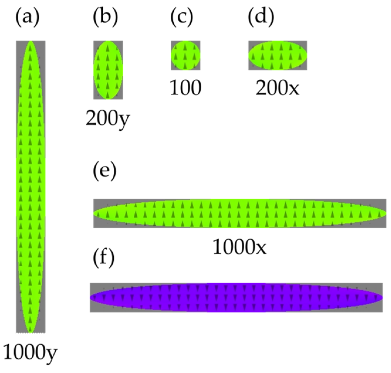
, corresponding to the modelled materials. The nanoparticles considered here are 30 nm thick and show an elliptical in-plane shape. Thus, they are elliptical flat cylinders. The ratios of the semiaxes of the ellipses encompass values 1 (circle), 2 and 10, the short semiaxis being constantly held at 100 nm. The present selection of sizes relies on the existing examples of thin magnetic particles [
46]. The considered shapes are shown in
Figure 1. In what follows, the particular shapes will be labelled by the material NiFe for permalloy and Co for cobalt. In the latter case, the orientation of the easy axis x or y will be indicated by Ax or Ay, respectively. The semiaxis ratio of each shape will be specified by giving the length of the longer semiaxis. Consequently, the permalloy particle with the semiaxes 100 nm in the x direction and 200 nm in the y direction will be denoted by NiFe200y, whereas when the longer axis is 1000 nm in the x direction the symbol will be NiFe1000x. Correspondingly, we will have CoAx200y as the label for the easy axis of cobalt in the x direction and the ellipse’s long semiaxis of 200 nm in the y direction.
These are practically realisable nanoparticles. An external magnetic field is applied along the vertical axis y.
The magnetic field is varied with a pace of
and the equilibrium configuration ensuring the energy minimum is found for each value with the use of the software Mumax3. The search for the equilibrium configuration of the magnetic moments in each voxel starts with an initial configuration that is optimised using, in sequence, the commands
relax and
minimize of the Mumax3 software [
42]. Both commands disable the precession term in the Landau–Lifschitz–Gillbert equation so that we are left with a damped movement of spins in the energy landscape formed by the actual configuration of spins in all the voxels. The command
minimize reduces the residual torques that allow one to attain an energy minimum to the level
of relative accuracy. The minimisation being based on the steepest descent method the minimum found is the one closest to the initial configuration and not necessarily the global one. Thus, the obtained states are generally metastable. For every minimum, it is possible to generate the corresponding magnetisation map. The maps are represented with a colour code.
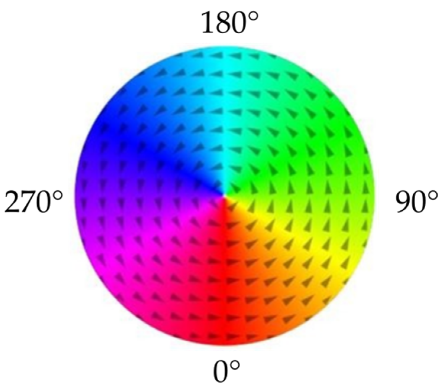
Figure 2 provides a colour code for the in-plane coordinates of the magnetisation arrows. The out-of-plane coordinate is rendered with a degree of grey so that an arrow pointing straight upwards will correspond to white and an arrow pointing downwards to black. Alternatively, a magnetisation map can be illustrated by ensembles of perspective views of arrows. Both representations will be used to visualise the results depending on the needs.
In what follows, the configuration with all the spins oriented upwards, taken as the initial configuration in the strong positive field
, will be denoted FM and marked with green colour (see
Figure 1e and
Figure 2 (90°)). The opposite uniform magnetisation will be denoted rFM (reverse ferromagnetic) and marked with violet colour (see
Figure 1f and
Figure 2 (270°)).
For every shape and orientation of the magnetocrystalline axis and field orientation, we have recorded the hysteresis loop. The corresponding magnetisation maps have been visualised and discussed.
3. Results
Three series of numerical experiments are presented below: (i) all the nanoparticles made of permalloy (
Section 3.1), (ii) all the nanoparticles made of cobalt with its easy axis in the
direction, i.e., parallel to the probing field (
Section 3.2), and (iii) the same cobalt with the easy axis oriented in the
direction, i.e., perpendicular to the field (
Section 3.3). In each case, we show the evolution of magnetisation under a variable applied field starting from the vertical upwards (
) direction and then decreasing its strength through zero to negative values down to the downwards direction (
). Further, we present selected magnetisation maps corresponding to the consecutive stages of the magnetisation reversal (remagnetisation) process.
3.1. Permalloy
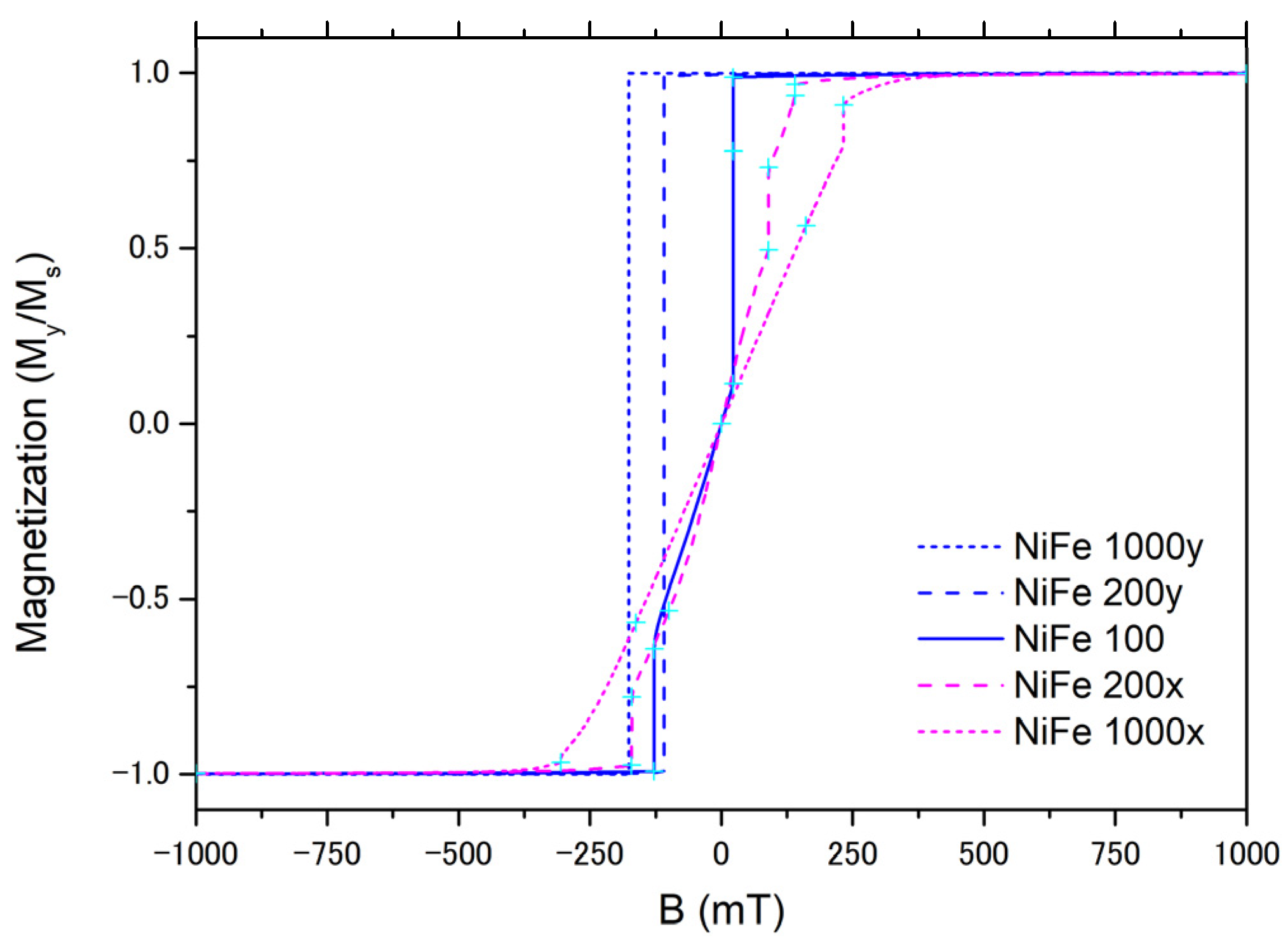
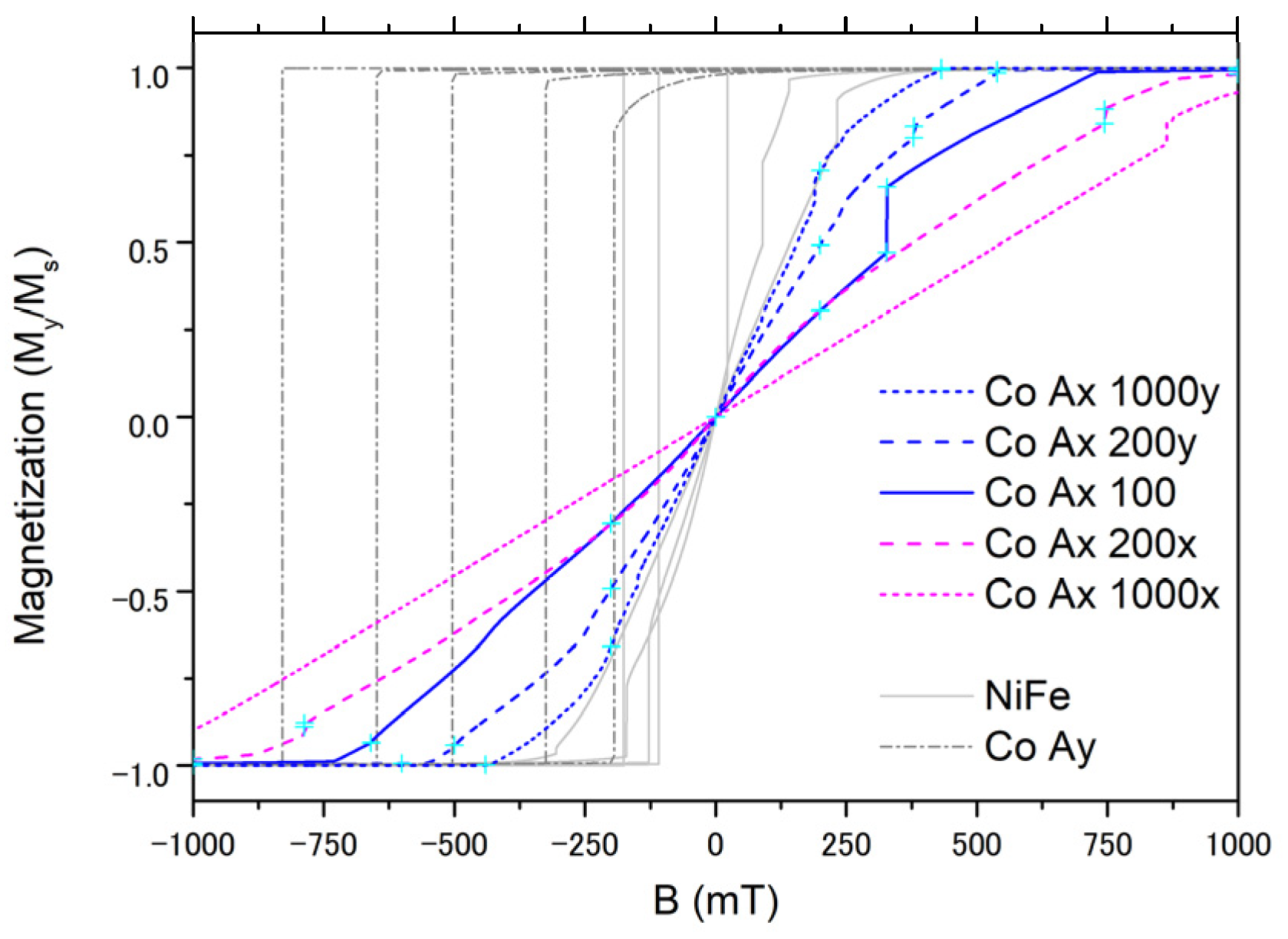
The net magnetisation of the permalloy nanoparticles as a function of the external magnetic field applied in the vertical direction
is shown in
Figure 3. The thought experiment starts from the right upper side with
, corresponding to a strong field upwards. The equilibrium magnetisation then is close to the saturation and well homogeneous parallel to the field. The field strength is subsequently diminished with a step of
. Further, the field crosses zero and finally increases to
in the opposite direction. By this, one sees half of the hysteresis loop for each shape of the nanoparticle.
Noteworthy is that the hysteresis loops for the shapes elongated parallel to the measuring field, i.e., with a long semiaxis in the direction, are well squared, whereas those for circular and elongated perpendicular to the field show some steps and sloped regions. This confirms the quasi-single-spin (macrospin) type of behaviour of the narrow particles oriented parallel to the field. The finite slopes and steps reflect non-homogeneous spin configurations arising in the course of the remagnetisation process. Some of the configurations are presented in the following figures.
The magnetisation switching of the longest particle NiFe1000y proceeds by practically one single jump from FM configuration to rFM between , i.e., just before switching and , i.e., one field step after switching.
The remagnetisation of the particle NiFe200y occurs in principle in a similar one-step way between the values of the magnetic field and . The hysteresis loop, thus, is narrower. A closer insight into the evolution of the magnetisation reveals tiny peripheral regions where the magnetic moments deviate from being parallel to the long axis and, thus, forming a subtle S-shaped configuration. This is the most often initial stage of remagnetisation.
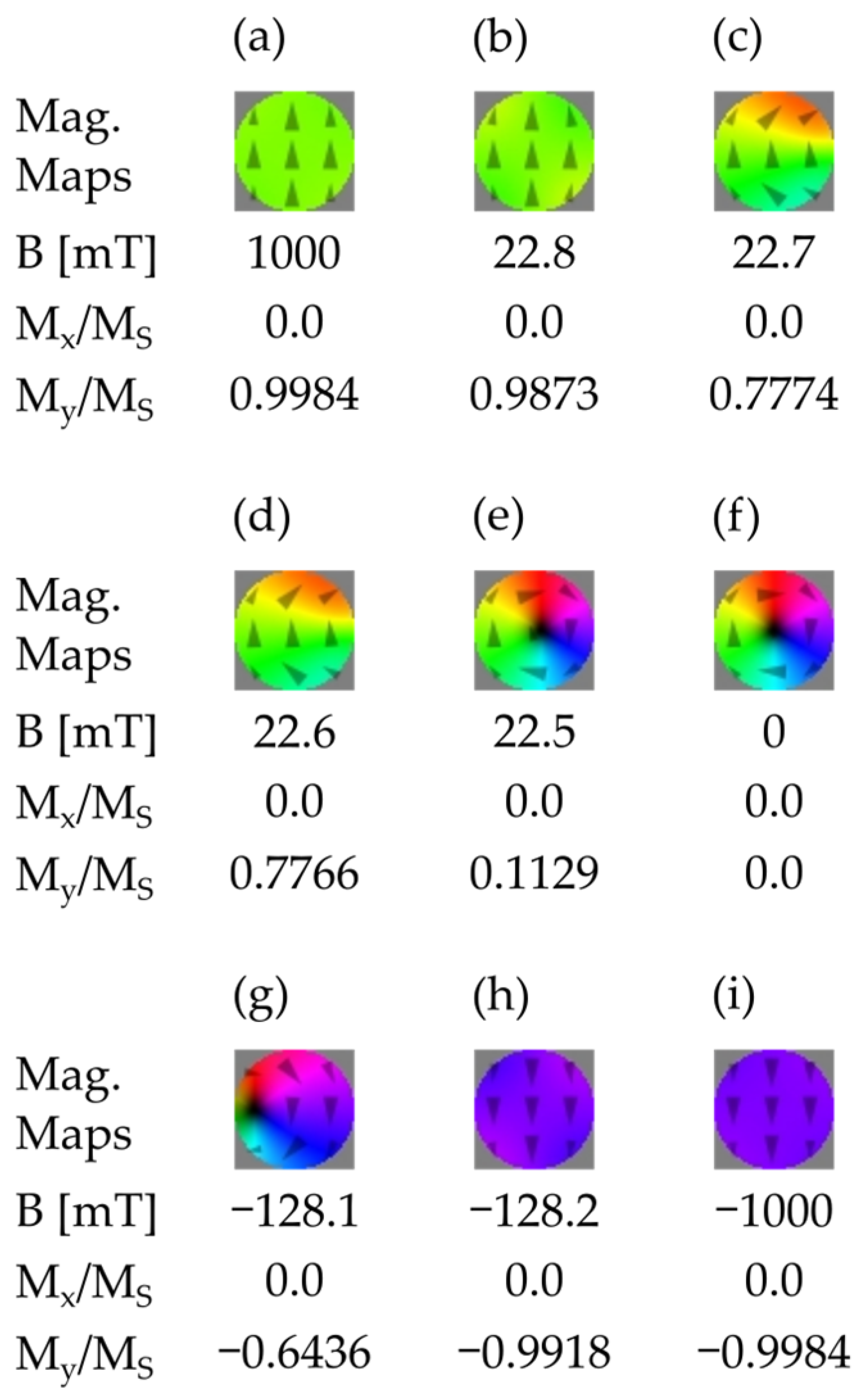
An S-shaped deviation from homogeneity is sometimes also an initial stage of a vortex, i.e., a structure where the magnetisation vector revolves around a point or, better to say, around a short axis of the system parallel to the z direction perpendicular to the image plane. An example is visible in
Figure 4 for a circular shape. In this case, the initial S-shaped configuration (
) transforms into a C-shaped one (
and
) and further rolls up to the fully developed vortex at
and
, which at
starts to be moved away, giving room to a reversed parallel configuration with transitorily a trace of an S-shaped deviation
The vortex configuration is in fact not entirely flat. A vertical component (
z direction) grows progressively when approaching the core of the vortex, as is shown in
Figure 5. Due to the symmetry of the problem, the orientation of the vortex and, consequently, the direction of the core sticking out of the plane is equiprobable up and down (
and
).
Magnetisation maps for the case when the long axis of the particle is directed perpendicular to the magnetic field are shown in
Figure 6. Here, again, an initially S-shaped deviation evolves to a C-shaped one, and further, towards a vortex, which seems to enter the shape from the left (
Figure 6e). The shape anisotropy is too weak here, so that the system does not take on the equilibrium zero-field single-macrospin configuration with the magnetisation along the long axis. The latter occurs for a ratio of the semiaxes equal to 10; see
Figure 7.
Noteworthy is that in some configurations of the NiFe200x system, the magnetisation shows a non-zero horizontal x component. The sign of this component is, of course, not determined due to the symmetry of the system. Formally, the magnetic moment as well as the magnetic field being pseudovectors (axial vectors), an elliptical particle with a magnetic field along its axis shows invariance against composition of mirror reflection in the plane normal to the ellipse and containing the axis (here, it is the
yz mirror plane) with time reversal [
47]. Consequently, the energy of a magnetic moment
and
in the absence of an
component of the field
B should be equal. We have checked that the counterparts of the obtained maps transformed by the described symmetry element have the same energy. These are examples of spontaneous symmetry breaking [
48,
49].
For the particle NiFe1000x, the evolution also starts with an S-shaped deformation (
Figure 7b), but no vortex forms. Instead, the system goes to the macrospin horizontal configuration. This is, thus, an instance of a shape anisotropy prevailing in spite of the lack of the external field in this direction. An S-shape (
Figure 7f) precedes the final reverse ordering.
The non-zero -component of magnetisation is also well pronounced as a next instance of the spontaneous symmetry breaking.
Noteworthy is that quitting the orientation and arrival at the one shows an asymmetry. This indicates that the path of the energy minima is not unique. However, close to the configurations are fairly symmetric with respect to the x axis, in which case the system shows properties of a macrospin.
3.2. Cobalt, Easy Axis in the Y Direction
When the easy axes of the shape and magnetocrystalline anisotropy are parallel, the overall anisotropy is enhanced. Both contribute to the particle’s behaviour as a macrospin, i.e., well homogeneous magnetisation throughout the whole volume.
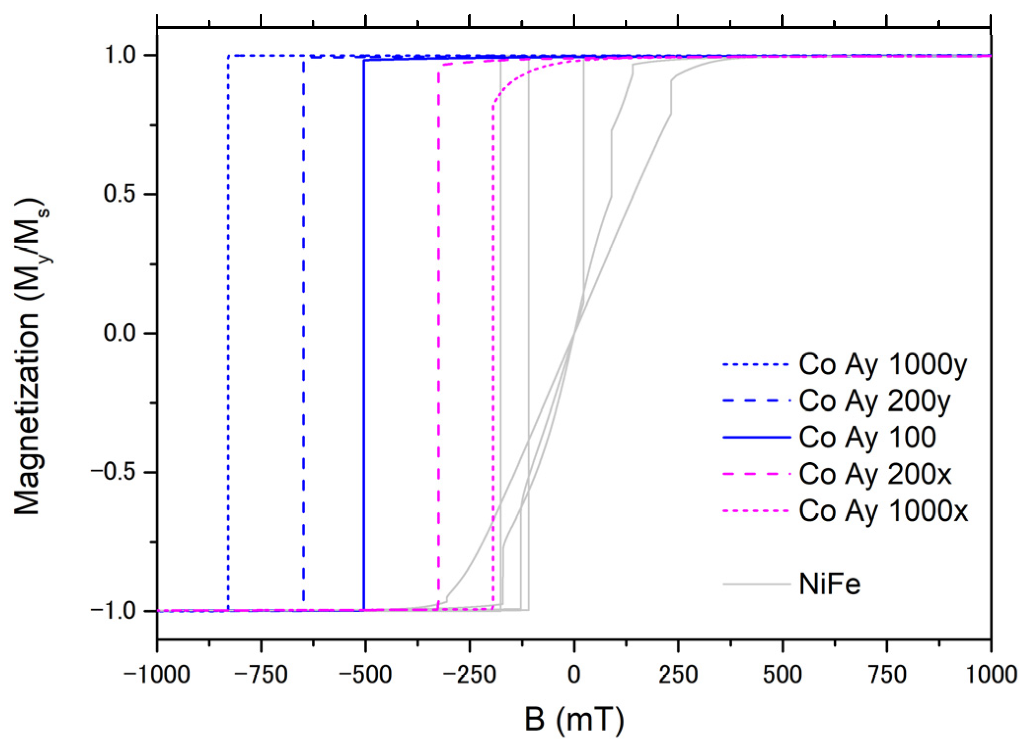
Consequently, the most pronounced feature of the switching in the cobalt nanoparticles with the particle’s long axis parallel to the magnetocrystalline easy axis is that the coercive fields are markedly stronger (
Figure 8). This results from a synergy of the magnetocrystalline and shape anisotropy enhancing the magnetisation alignment along the
y axis. The hystereses are more squared even for the long axis in the
x direction. The only remarkable feature is a rounding in the upper part of the switching curves CoAy200 and CoAy1000. The roundings of the reversal curves visible in
Figure 8 can be attributed to clear S-shaped deformation, similar to those in
Figure 7b, visible in the corresponding magnetisation maps (not shown). Otherwise, the switching is one-stage in the adopted approximations. The ensemble of phenomena described above reflects magnetocrystalline anisotropy prevailing over the shape anisotropy.
3.3. Cobalt, Easy Axis in the X Direction
The case of a magnetocrystalline easy axis perpendicular to the applied field axis of the particle is the most intriguing one. The competing magnetocrystalline and shape anisotropies give rise to the richest variety of phenomena.
The curves in
Figure 9 correspond to the switching in this case.
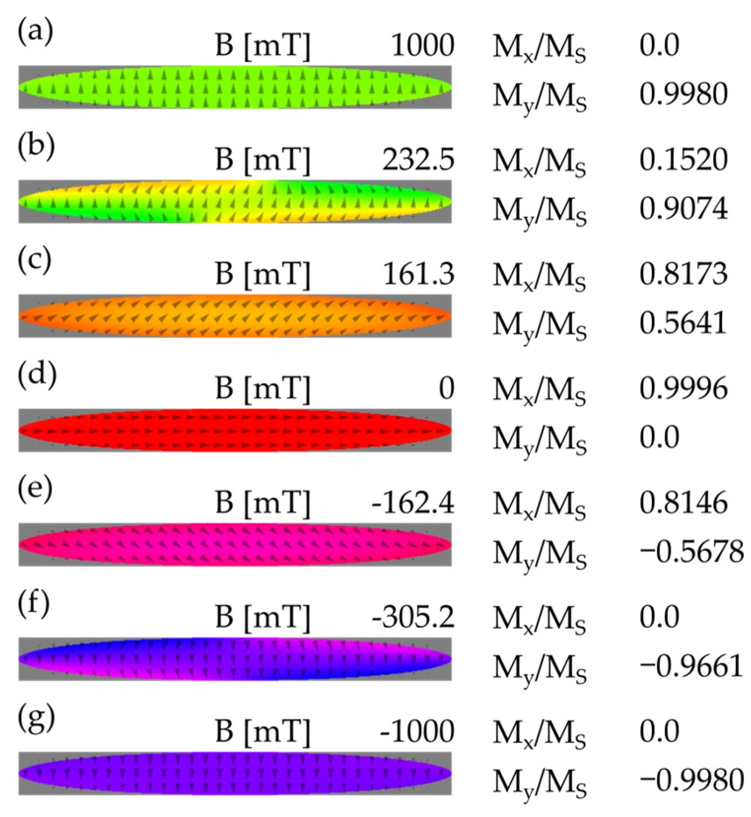
Compared with the previous cases, the switching curves are much less steep and more structured, but qualitatively, the evolution of magnetisation maps is similar to that of horizontally elongated particle NiFe1000x depicted in
Figure 7. To keep the magnetisation parallel to the field in the case of the easy axis oriented along the particle’s axis, i.e., for the sample CoAx1000x, one has to increase the field up to
. In a field as strong as
, a ubiquitous S-shaped deviation from the parallel orientation is visible. Remarkable is that in the relatively strong fields
as well as
, the magnetisation is practically uniform and it subtends a constant angle with the magnetic field. This is one more example of a nanoparticle behaving as a single spin (macrospin), this time in a strong potential of anisotropy, which forces the system to a parallel horizontal configuration at
.
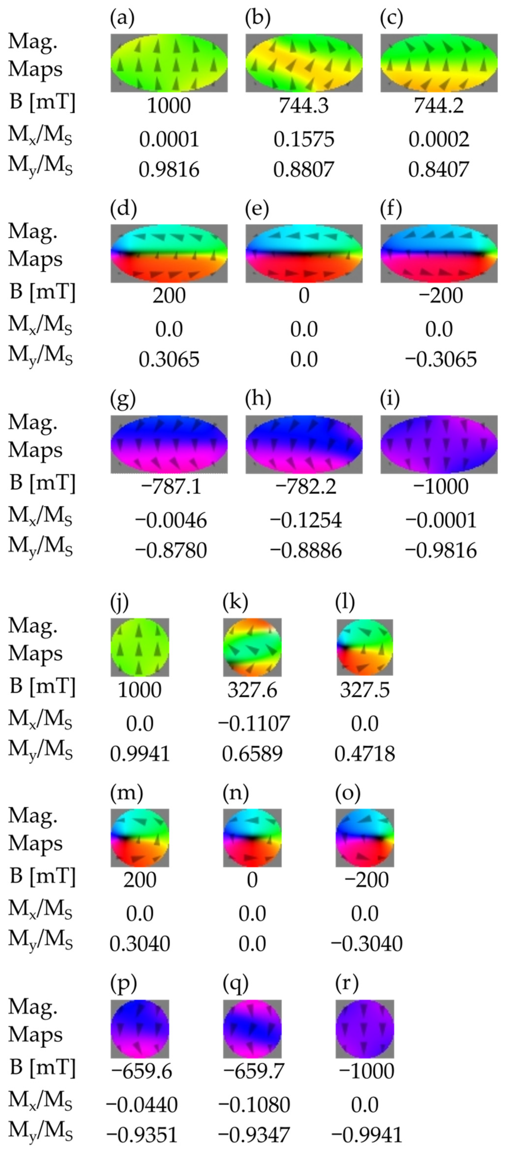
Remagnetisation of the shorter system CoAx200x, see
Figure 10, starts with an S-shaped deviation evolving to a flattened vortex (
Figure 10d–f), which can be assimilated to two domains with a horizontal domain wall. With a reversed field, there is apparently no symmetry:
Figure 10g–i show rather an evolution of a reversed C-shape to an S-shape. In a regular circle (
Figure 10j through
Figure 10r), the sequence is fairly similar.
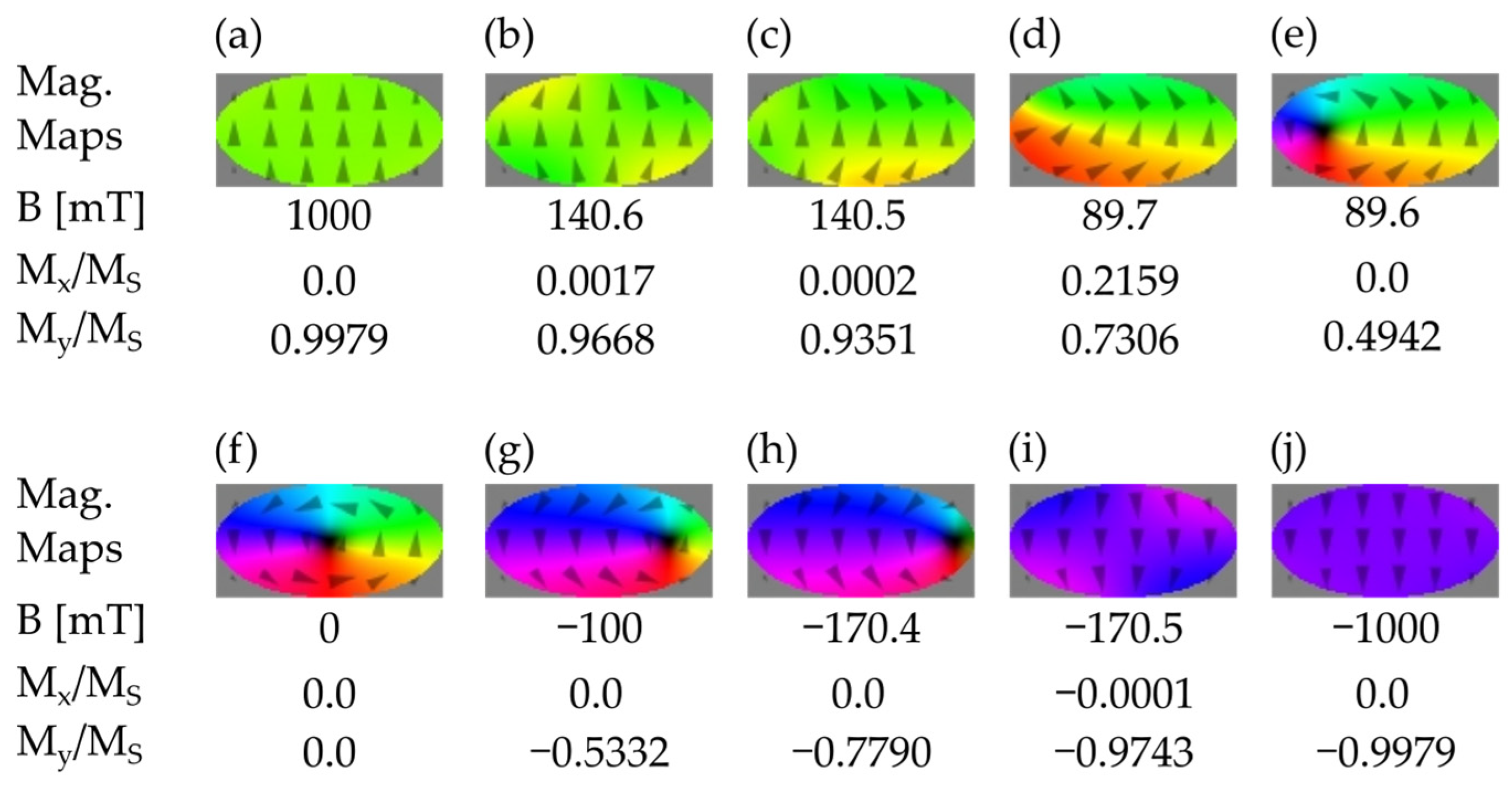
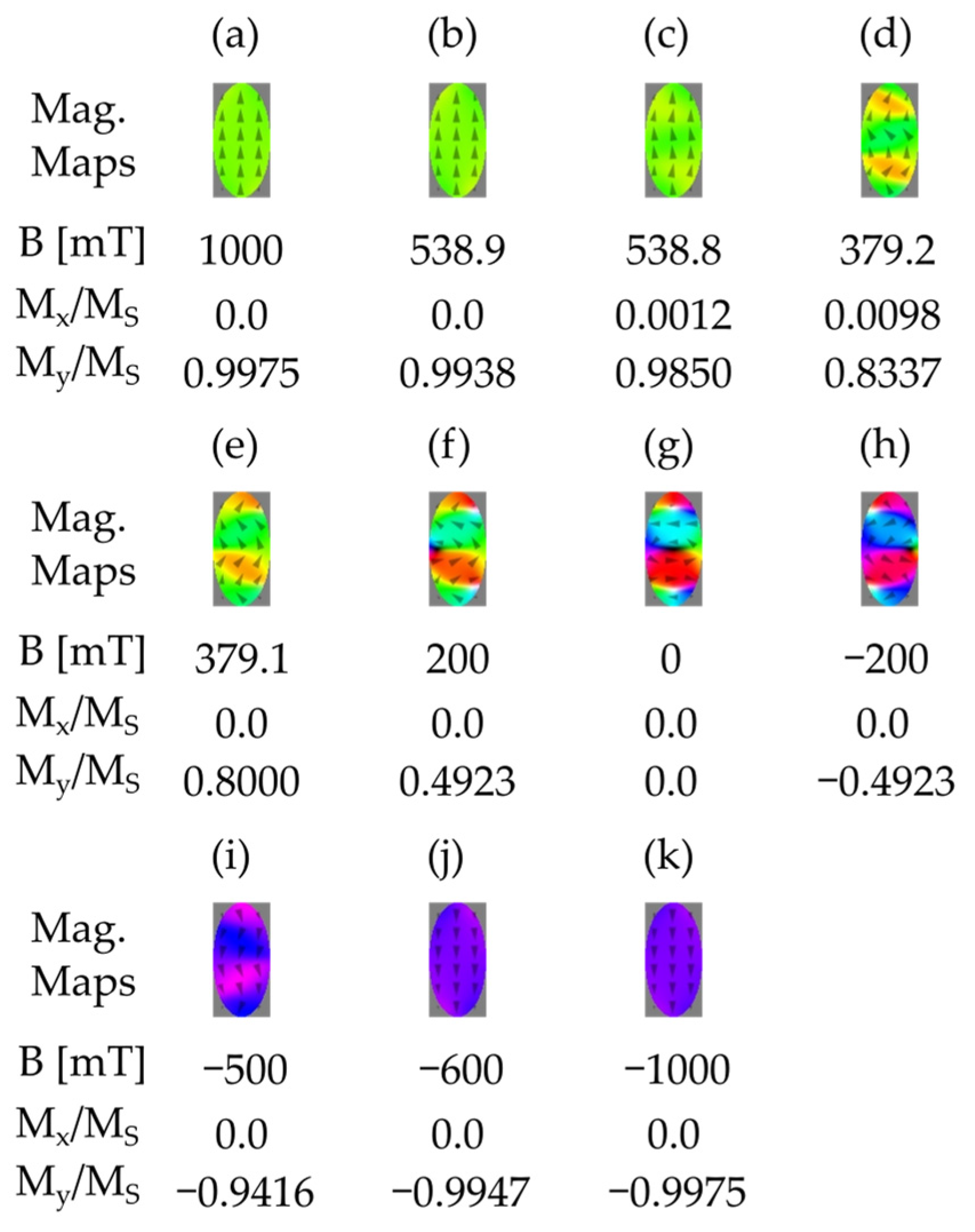
The most interesting switching sequence occurs when the easy magnetocrystalline axis of cobalt is perpendicular to the long axis of the particle. The hystereses are broadest and far from squaring.
The slight S-like deviation is also present at
, but further (at
) evolution goes through a zig-zag configuration (
Figure 11d,e). The corners of the zig-zag structures show strong out-of-plane components visible in (f), (g) and (h) as black and white areas corresponding to spins oriented backward and forward from the image plane, respectively.
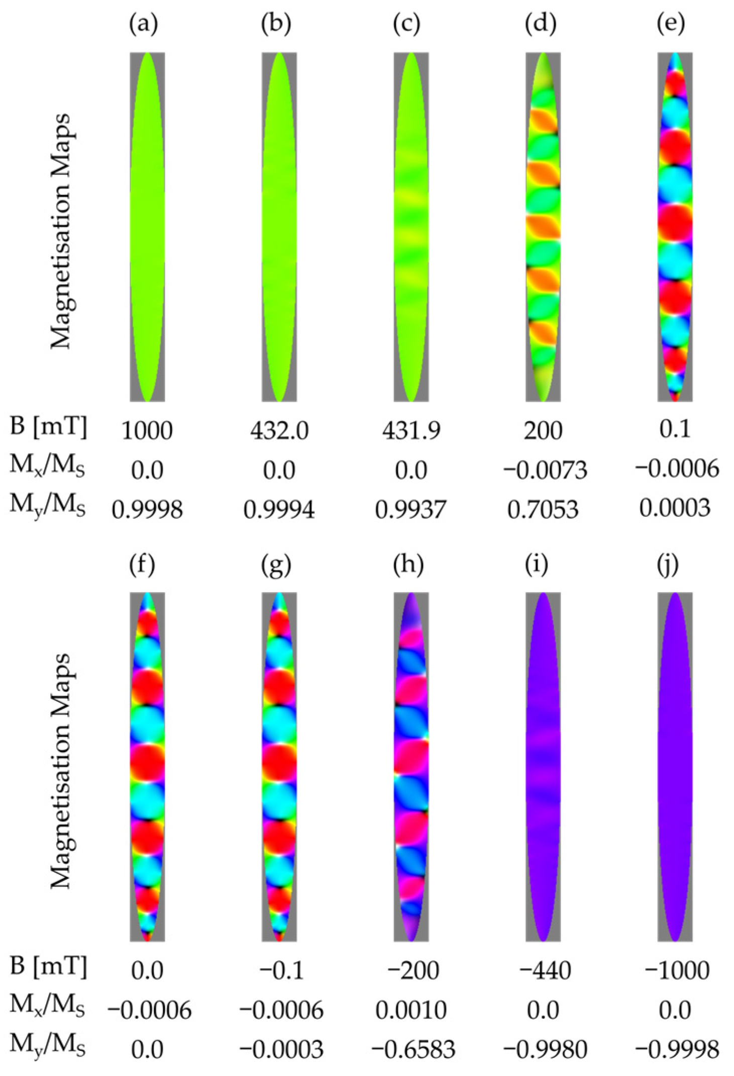
The CoAx1000y nanoparticle magnetises itself parallel to the
-axis with a field as strong as 1 T. However, already at
mT a zig-zag modification can be discerned instead of a single S-shape, as shown in
Figure 12c.
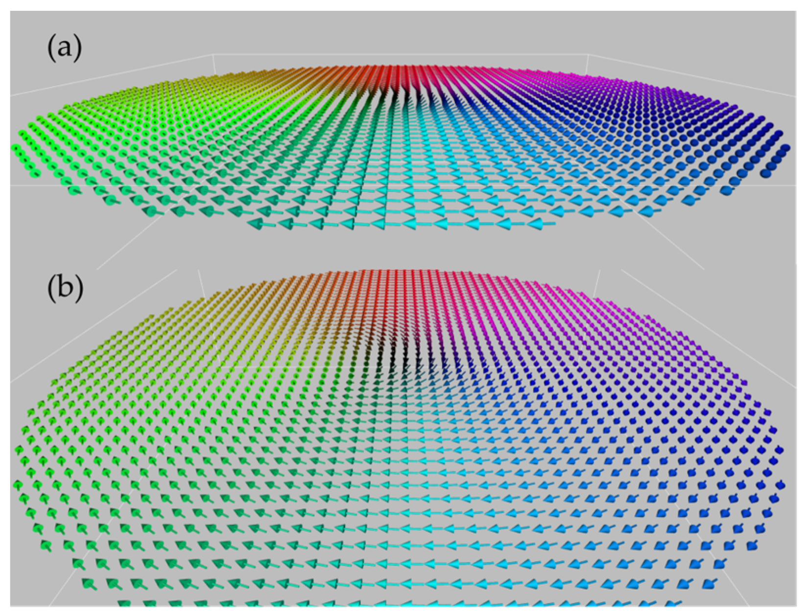
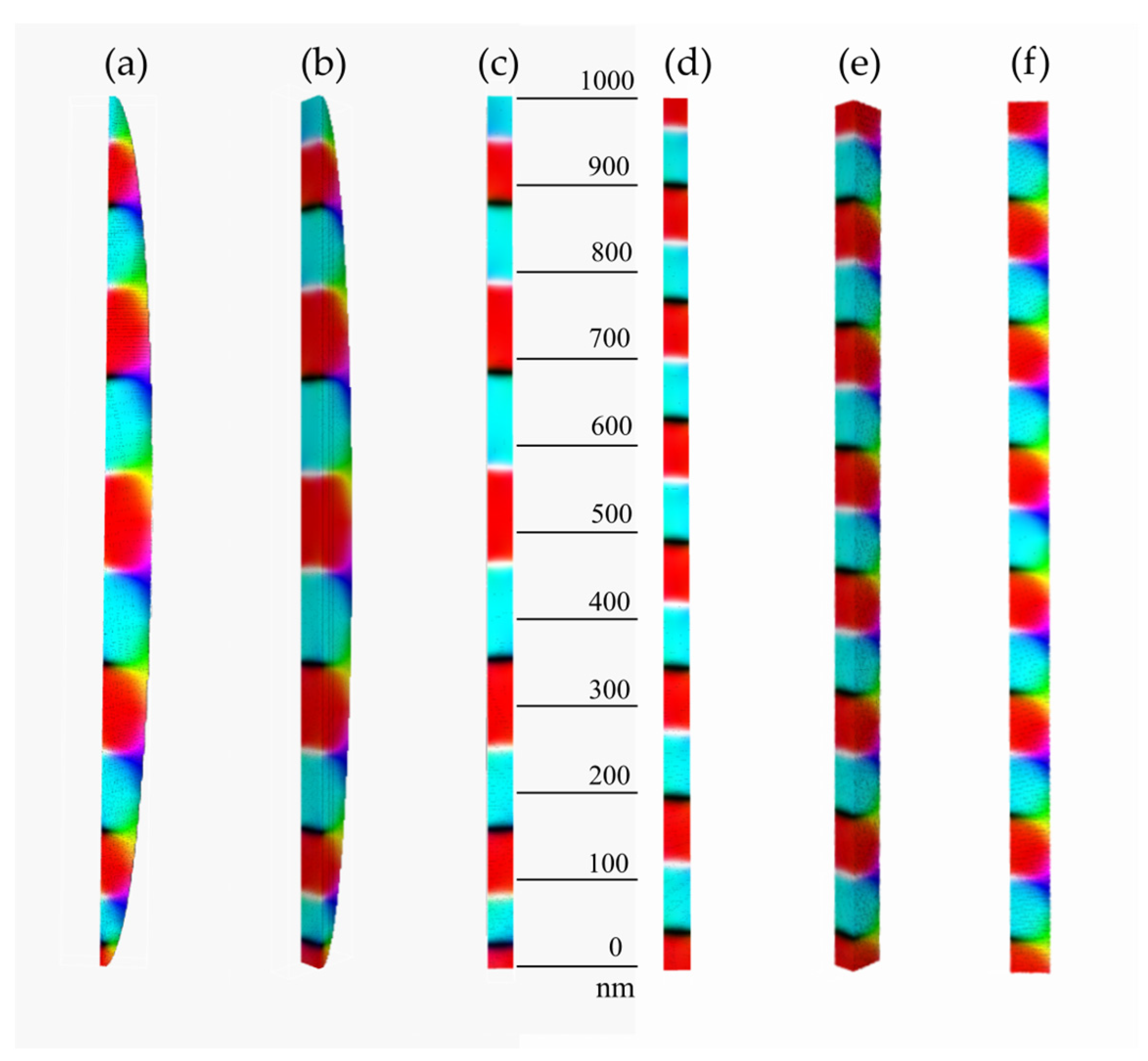
The zig-zag intensifies, giving rise to a sequence of a superlattice-like oppositely magnetised regions separated by deformed vortices,
Figure 12e–g. With the field tending to zero, the vortices acquire more and more pronounced out-of-plane components (represented by black and white colours). The out-of-plane magnetisation components are, however, of a different nature than the stripe domains. To better visualise the features of this configuration, we show in
Figure 13a–c a section of the magnetisation map at
. For comparison, we present in the same
Figure 13d–f analogous section of a rectangular stripe. One can see that the domain boundaries are much closer to being equidistant. This indicates that the extent of the domains is a function of the particle’s width in the
x direction.
The size of the domains in
Figure 12f and
Figure 13, measured as the distance between neighbouring black–white or white–white fairly sharp boundaries, varies with the particle’s width. Looking at the scale in
Figure 13a–c, one sees that the domain size in the direction of the long axis grows from about 50 nm close to ends of the particle to almost 100 nm in the central part. This indicates a possibility of designing devices with a tuneable variable periodicity controlled by the width of the shape (see e.g., ref. [
15]). The observation is corroborated by the calculus for a cuboid circumscribed on the elliptical cylinder, where the domain boundaries are close to equidistant.
It is well-known that equally spaced interfaces (superlattices) produce forbidden propagation gaps for different types of waves typical for phononic, photonic and magnonic crystals [
50,
51,
52]. Thus, one should expect useful transmission properties of spin waves/magnons with wave vectors parallel to the long axis of the particles with possible extension to nanowires. The effect of modulated distances of the domain boundaries on the magnon transmission properties is still to be studied. It is also evident that the transmission properties will strongly depend on the polarisation of the spin waves, whereas in the
xy plane the system of domains resembles a superlattice of oppositely oriented ferromagnets and a system of sticking sharp ridges is visible in the z direction.
4. Discussion and Conclusions
The interplay of magnetocrystalline and shape anisotropy gives rise to a variety of magnetic configurations of nanoparticles as a function of an applied magnetic field. In this note, we have studied circular and elliptic nanoparticles made of magnetically isotropic permalloy and, in contrast, of hexagonal cobalt marked with a strong uniaxial anisotropy. The evolution of the magnetisation maps in the course of remagnetisation has been computed and illustrated in coloured diagrams. The evolution usually starts with an S-shaped deviation from the uniform parallel configuration. In systems close to a circular shape, a vortex or a number of vortices occur with a core/cores where the magnetic moment is directed perpendicular to the particle’s plane. The reason for this out-of-plane magnetisation is not related to a perpendicular magnetic anisotropy, as is the case in the stripe domains [
8]. As the magnetic field is always parallel to one of the semiaxes of the ellipse, the formation of vortices is an instance of spontaneous symmetry breaking. We have checked, by slightly variating the initial conditions, that both equivalent orientations of a vortex are equiprobable. The configuration of an elongated particle made of material with an easy axis perpendicular to the long axis obtained with an external field parallel to the long axis consists of alternating ferromagnetic domains separated by vortex-like interfaces. The structure persists in the zero field. This suggests a possibility of fabrication of magnonic and affine systems by an appropriate selection of shape and magnetocrystalline anisotropy. In this respect, it is interesting to check to what extent the obtained magnetic configurations are stable. To cast a light on this issue, we compared the total energies of the configurations obtained for the particular shapes starting from an initial random distribution of voxel spins with the configurations obtained for the same shapes by the magnetic treatment, i.e., by magnetising them to the saturated state and subsequently, gradually releasing the field to zero. The latter state is marked in
Table 1 as “History” to indicate a magnetic treatment undergone. Whenever the energy of the “History” case is lower than that obtained from a random initial distribution, the configuration should be viewed as more stable. In the opposite case, it is metastable and one may expect its evolution or transition to a more stable configuration. In some cases, the energies are equal to the present accuracy. We have checked that the corresponding configurations are similar. The corresponding configurations are to be treated as the most stable.
The system of quasi superlattice-like domains in
Figure 12 and
Figure 13 seems to be the most promising for application in magnon wave transmission. It is clearly a result of the magnetocrystalline anisotropy prevailing over the shape anisotropy. The impact of the ratio of magnetocrystalline and shape anisotropy attained by using different materials will be studied in a forthcoming article.
The novelty of the present work resides in the systematic study of the magnetisation switching mechanisms in a well-defined class of magnetic thin elliptical nanocylinders of constant thickness and variable semiaxis ratios under an applied external magnetic field in well-controlled conditions. The size of the defined nanoparticles corresponds to those found in the existing literature [
46], but is also close to the magnetic inclusions in minerals [
6]. The thickness of the cylinders was selected to be much lower than hundreds of nms to avoid the formation of stripe domains, whose origins involve quite different mechanisms [
8,
9,
11]. The results indicate to what extent the nanoparticles under study can be treated as macrospins. On the other hand, strong competition of the shape and magnetocrystalline anisotropies is shown to give rise to a superlattice-like sequence of domains that may be interesting in the context of magnonics.


