Abstract
High-temperature fasteners are metal parts of gas turbines and steam turbines, which work at high temperatures and under stress for a long time. However, the frequent seizures of fasteners bring great trouble to the normal maintenance of power plants. In this paper, three kinds of dense and controllable CrAlN-based gradient multilayer coatings were prepared on the samples and screws by arc ion plating (AIP) technology. The morphology, composition, structure, nano hardness, adhesion, residual stress, and room temperature tribological performance of the coating were investigated. To evaluate the high-temperature, anti-seizing performance, coated screws were heated to 700 °C for 140 h with a torque of 20 N·m. The results indicate that the CrN/CrAlN multilayer coating shows better comprehensive properties. The characterization of coated screws proved that the coating structures obtained on the screws were similar to the flat samples. However, the as-prepared coating on the screws showed different thickness variation rules, which was related to the clamping method, deposition distance, and screw shape. After a simulation service, the thread of the screw remained intact with similar structure and thinner thickness. The above results indicate that the high-temperature seize prevention of fasteners can be successfully achieved by preparing a CrAlN-based multilayer coating, which is suitable for fasteners with service temperatures below 700 °C.
1. Introduction
Fastener seizure is one of the common failure modes of sliding contacts under high-speed heavy loads and high-temperature conditions, which widely exists in electric power, automobile, coal mining, steel manufacturing, and forming industries [1,2,3]. The bolts and screws in gas turbine burners, combustion and pressure cylinders, turbine cylinders, and exhaust cylinders usually work under high temperature and stress for a long time [3,4]. Although the materials, specifications, and service temperatures of fasteners are not the same, their frequent seizures bring great trouble to the normal maintenance of power plants. Therefore, avoiding the occurrence of fastener seizures can improve the maintenance efficiency of power plants, the re-utilization rate of bolts, the economic benefits, and safety of power plants [5,6]. Many measures have been generally adopted to improve the anti-seizing performance of fasteners, such as controlling the surface hardness difference of materials during installation, applying solid lubricants, or anti-seize pastes [1,3,7]. However, the anti-seizing effect of these measures is limited. The sticking or seizing phenomenon often still occurs in the screw-thread fits running under long cycles, heavy loads, and high temperature conditions. Furthermore, there are few studies based on physical vapor deposition (PVD) technology, which is more environmentally friendly and more efficient than pastes [1,2,3,6,7,8].
Excellent anti-seizing performance of high-temperature bolts requires the thread surface with better wear resistance, oxidation resistance, corrosion resistance, low expansion, and good toughness. Surface coating technology is an effective method to improve their service life and reliability. The hard nitride coating prepared by PVD technology has the advantages of wear resistance, oxidation resistance, corrosion resistance, precise thickness control, etc., which is expected to achieve the high temperature seize prevention of fasteners [8,9,10,11]. Kwon et al. [3] prepared a silver-palladium (Ag-Pd) alloy coating on high-temperature stud bolts using an ion plating method. Kashyap et al. [8] prepared a Mo/DLC multilayer coating on 304 stainless steel using HiPIMS technology to achieve the purpose of seize prevention. Thompson et al. [7] prepared MoS2 coating using solid sputtering as the anti-seize coating for nuclear bolts. Oerlikon Balzers has developed a 10 μm Balinit D (CrN) thread coating to improve the resistance to fretting wear and cold friction welding, which replaces the hard chrome coating for steam turbine bolts. Although a large number of nitride coatings have been successfully prepared with the PVD method, most of the current research is mainly focused on substrate samples [12,13,14,15,16]. There are still few a research and engineering applications for the actual components of gas turbines or steam turbine [11,17,18,19,20]. Therefore, in order to meet the demand of gas turbine fasteners under high temperature and stress for long periods of time, CrAlN coating was selected due to its high temperature oxidation resistance and corrosion resistance.
In this paper, the morphology, composition, structure, hardness, adhesion, residual stress, and room temperature tribological performance of three kinds of CrAlN-based gradient multilayer coatings on substrates were characterized. Subsequently, the coating was prepared on screws of gas turbines to evaluate the high-temperature, anti-seizing performance under simulated service conditions.
2. Experimental
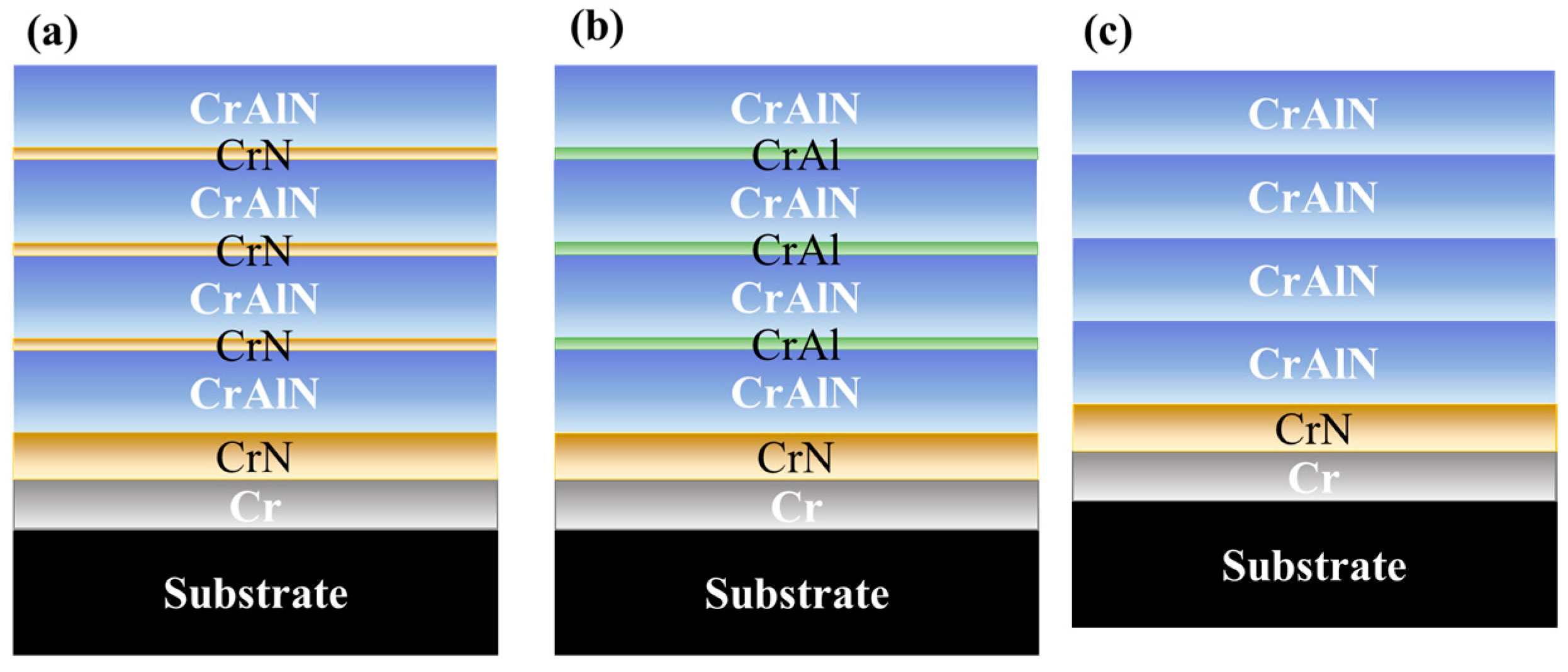
CrAlN-based gradient multilayer coatings were deposited on n-type (111) Si substrates, metal specimens (Ra ≤ 0.3 μm), and M8 screws of gas turbines using the AIP method with high purity Cr and Cr-70Al at% targets. Three different CrAlN-based gradient multilayer coatings with the structure of Cr metal base layer/CrN buffer layer/CrAlN functional layer were designed and prepared. The schematic diagrams of different CrAlN functional layers were labeled as 1-CrN/CrAlN, 2-CrAl/CrAlN, and 3-CrAlN coatings, which are shown in Figure 1a, Figure 1b, and Figure 1c, respectively. The detailed monolayer deposition parameters of the metal base Cr, buffer CrN, functional CrN, functional CrAl, and functional CrAlN monolayer in Figure 1 were the same, which are listed in Table 1. The chamber was pumped down to 2.0 × 10⁻³ Pa and heated to 450 °C, simultaneously. Meanwhile, the temperature was kept at 450 °C during the subsequent ion cleaning and coating process. The sample and screw surfaces were then cleaned and activated by argon ion etching and AEG etching step by step. Then, the 1-CrN/CrAlN, 2-CrAl/CrAlN, and 3-CrAlN coatings were deposited according to the parameters in Table 1.
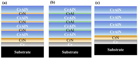
Figure 1.
Schematic diagrams of (a) 1-CrN/CrAlN, (b) 2-CrAl/CrAlN, and (c) 3-CrAlN gradient multilayer coatings.

Table 1.
The deposition parameters of CrAlN-based gradient multilayer coatings.
The morphology, structure, composition, and elemental distribution of different coatings were characterized via a scanning electron microscopy (SEM, JSM6490-LV, JEOL, Tokyo, Japan), X-ray diffraction (XRD, XRD-6100, Shimadzu, Kyoto, Japan), and energy dispersive spectroscopy (EDS). The roughness Ra was measured using a HOMMEL-ETAMIC W10 meter (Jenoptik, Villingen-Schwenningen, Germany). The nano-hardness and elastic modulus were acquired using the nano-indentation instrument (NHT2, Anton Paar, Graz, Austria). The adhesion strength of the coating was quantitatively measured using the scratch meter (RST3) (Anton Paar, Graz, Austria). The curvature of the uncoated and coated Si substrate was measured with a film stress tester (FST-1000, SuPro, Shenzhen, China), and the residual stress of the coating was calculated using the following curvature method Stoney formula [21]:
where σ is the coating stress, Es is the substrate elastic modulus, hs is the substrate thickness, νs is the substrate Poisson ratio, R1 is the uncoated substrate curvature radius, R2 is the coated substrate curvature radius, and hc is the coating thickness.
The tribological property of the coatings at room temperature was characterized using an HT-1000 tribometer (Zhongke Kaihua, Lanzhou, China). The friction pair was an Si3N4 ball with a diameter of 5 mm. The constant load was 4 N, and the nominal diameter of the wear track was 3 mm or 6 mm. The rotation speed was 380 r/min, and the sliding time was 60 min. To evaluate the high-temperature, anti-seizing performance, coated screws were heated at 700 °C for 140 h with a torque of 20 N·m. The morphology and structure of the coating on the screws before and after the simulated service were characterized.
3. Results and Discussion
3.1. Morphology, Structure, and Mechanical Properties
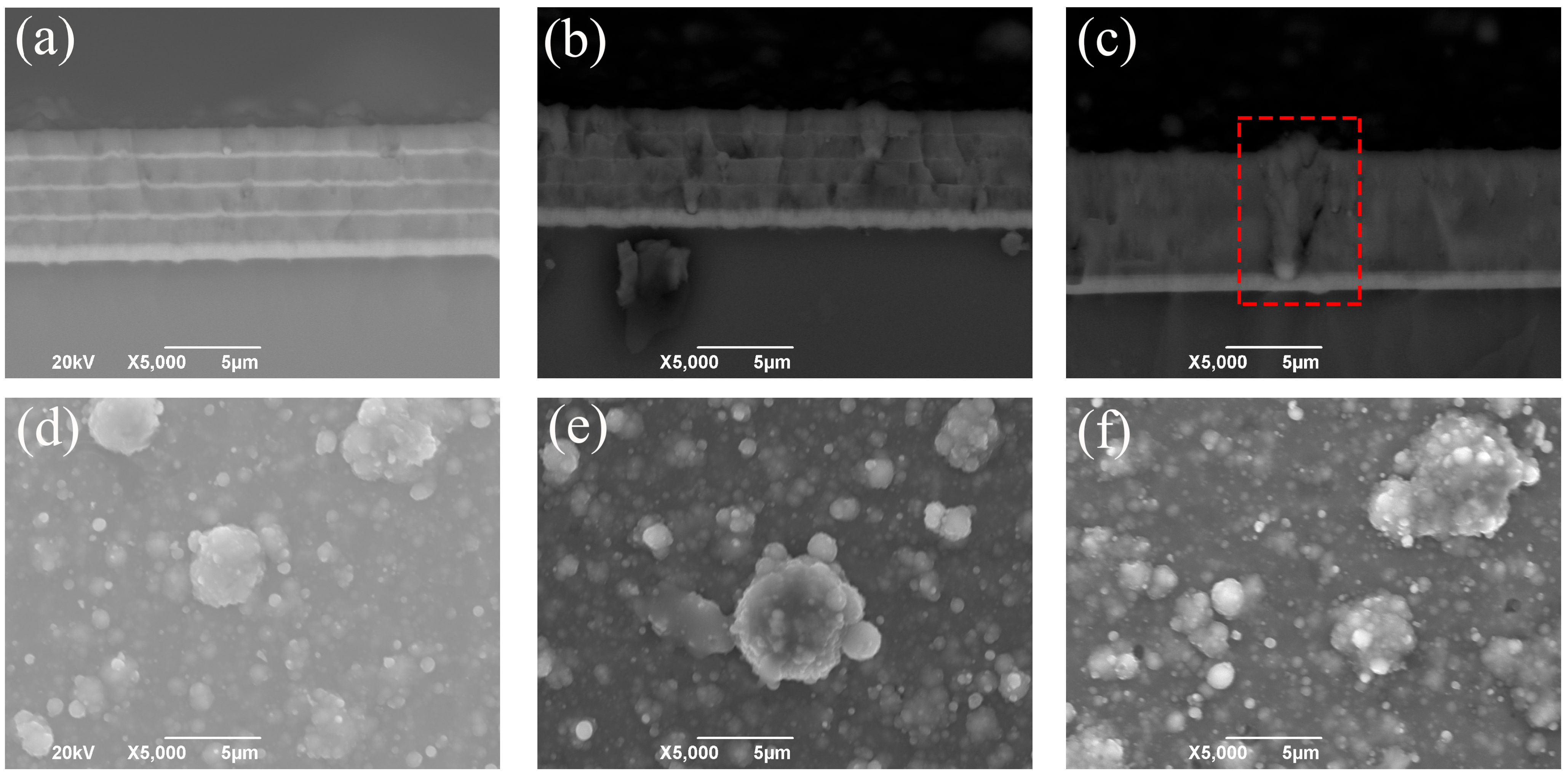
The SEM images of different CrAlN-based gradient multilayer coatings are presented in Figure 2. The cross-section and surface images were back-scattered electron images and secondary electron images, respectively. As shown in Figure 2a–c, the designed multilayer structures in the Figure 1 were successfully achieved. The thickness of 1-CrN/CrAlN, 2-CrAl/CrAlN, and 3-CrAlN coatings were 7 μm, 6 μm, and 6.5 μm, respectively. The thick and dark layer of the coating was CrAlN layer, while the thin and bright layer was Cr layer, CrN layer, or CrAl layer. In addition, the large particle that caused cracks in the 3-CrAlN coating are marked with red dashed box, which indicates that a thick CrAlN coating without a thin interlayer was easily affected by large particles (Figure 2c). Figure 2d–f show that a small number of large particles were detected on the surface of all samples. The maximum particle size was less than 10 μm. Furthermore, the surface particles of the 1-CrN/CrAlN coatings were smaller. To further evaluate the surface property, the roughness Ra was measured using the HOMMEL-ETAMIC W10 meter and is listed in Table 2. The Ra values of 1-CrN/CrAlN coatings were 0.15~0.18, which were lower than that of the 2-CrAl/CrAlN coatings and 3-CrAlN coatings. Therefore, the 1-CrN/CrAlN sample shows a lower roughness and smoother surface.
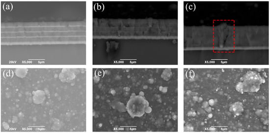
Figure 2.
Cross-section (a–c) and surface (d–f) SEM images of 1-CrN/CrAlN (a,d), 2-CrAl/CrAlN (b,e), and 3-CrAlN (c,f) gradient multilayer coatings.
Table 2.
Mechanical properties of the CrAlN-based gradient multilayer coatings.
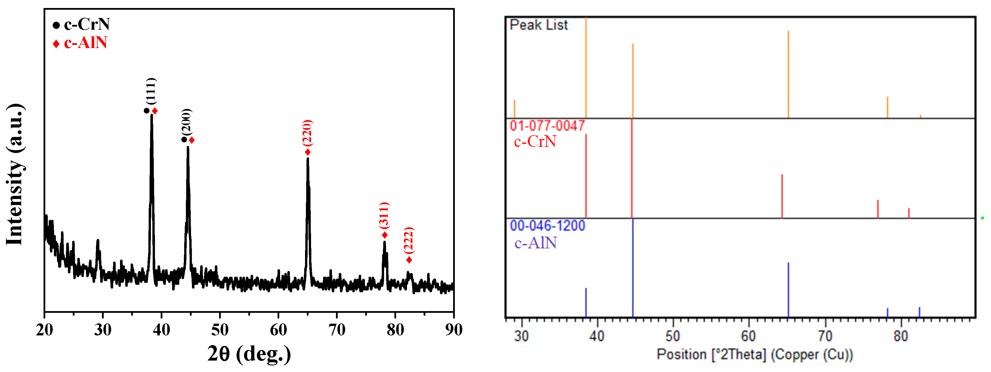
The XRD patterns of different CrAlN coatings were similar. Therefore, the XRD pattern of the 1-CrN/CrAlN coating was selected as a typical pattern and presented in Figure 3. The positions of the peaks were highly matched with the cubic AlN (c-AlN) phase. Meanwhile, the cubic CrN (c-CrN) phase was also detected due to their similar crystallographic parameters. Compared with the standard PDF cards of c-CrN (PDF no. 01-077-0047) and c-AlN (PDF no. 00-046-1200), preferential (111) and (220) orientations were found in the CrAlN-based coating. Furthermore, no peaks of the hcp-AlN phase were detected. The hcp-AlN is an unstable, brittle, and low hardness phase, which is a harmful phase in this work [22].
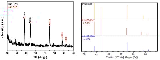
Figure 3.
Typical XRD pattern of CrAlN-based coating.
The mechanical properties of the CrAlN-based gradient multilayer coatings are listed in Table 2, including roughness, nano-hardness, elastic modulus, adhesion strength, and residual stress. The nano-hardness of the 1-CrN/CrAlN, 2-CrAl/CrAlN, and 3-CrAlN coatings were 22.8 ± 2.7 GPa, 24.1 ± 0.3 GPa, and 22.4 ± 2.9 GPa, respectively. The elastic modulus of the 1-CrN/CrAlN, 2-CrAl/CrAlN, and 3-CrAlN coatings were 344.7 ± 30.9 GPa, 354.2 ± 22.2 GPa, and 358.1 ± 35.0 GPa, respectively. In general, the nano-hardness and elastic modulus value ranges of all samples are 20~26 GPa and 300~400 GPa, respectively.
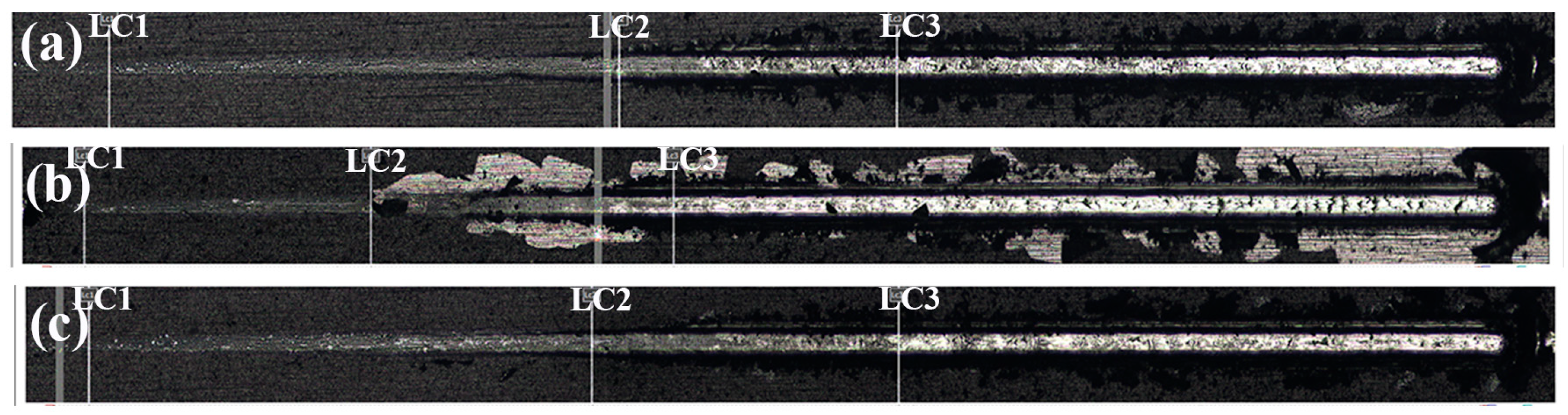
The loading speed of the indenter, loading range, and scratch length for the adhesion measurement was 50 N/min, 0~50 N, and 5 mm, respectively. Each sample was tested three times. The typical scratch morphologies and key LC1, LC2, and LC3 points are shown in Figure 4. The adhesion strength values of the 1-CrN/CrAlN, 2-CrAl/CrAlN, and 3-CrAlN coatings was 29.0 ± 1.0 N, 22.0 ± 0.8 N, and 29.6 ± 0.2 N, respectively, which were from the LC3 values and listed in Table 2. The adhesion of the 2-CrAl/CrAlN coating was the worst, with significant caving occurring at the beginning of the scratch (Figure 4b).
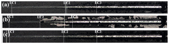
Figure 4.
Typical scratch morphology of 1-CrN/CrAlN (a), 2-CrAl/CrAlN (b), and 3-CrAlN (c) gradient multilayer coatings.
The residual stress of coating was calculated using the curvature method Stoney formula [21]. Each sample was tested three times, and the average values were taken. The average residual stresses of the 1-CrN/CrAlN, 2-CrAl/CrAlN, and 3-CrAlN coatings were −0.41 GPa, −0.41 GPa, and −0.37 GPa, respectively. The results indicate that the residual stress was compressive stress, which ranges from −0.41 GPa to −0.37 GPa.
3.2. Tribological Performance
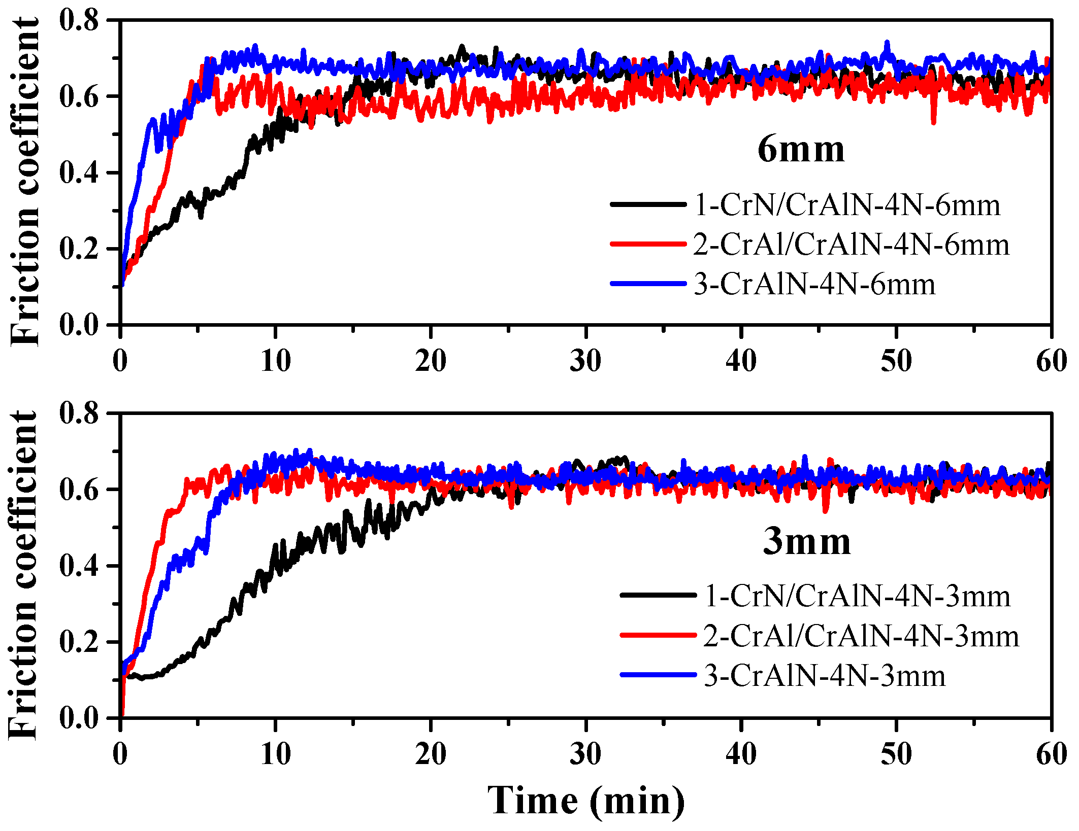
The dynamic friction coefficient of different CrAlN-based gradient multilayer coatings is shown in Figure 5. The friction pair was an Si3N4 ball with a diameter of 5 mm. The constant load was 4 N, and the nominal diameter of the wear track was 3 mm or 6 mm. The rotate speed was 380 r/min, and the sliding time was 60 min. The results indicate that the friction coefficient of different CrAlN-based coatings at room temperature was about 0.5~0.7. The friction curves of different nominal diameters were similar, while the friction coefficient of the 1-CrN/CrAlN coating was the lowest. The SEM image and EDS analysis of wear morphology are needed to further research the wear mechanism of the CrAlN-based coatings.
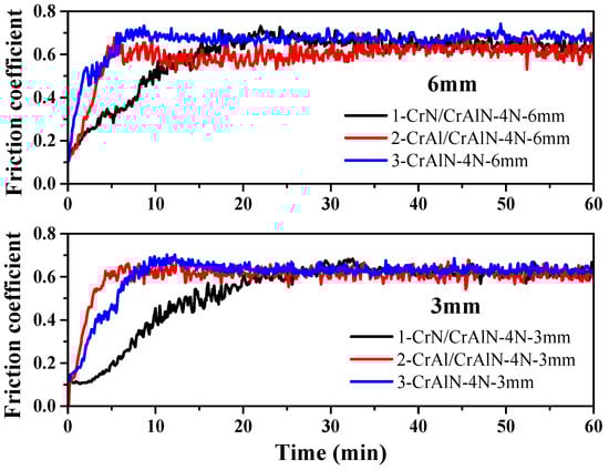
Figure 5.
Dynamic friction coefficient of CrAlN-based gradient multilayer coatings at room temperature.
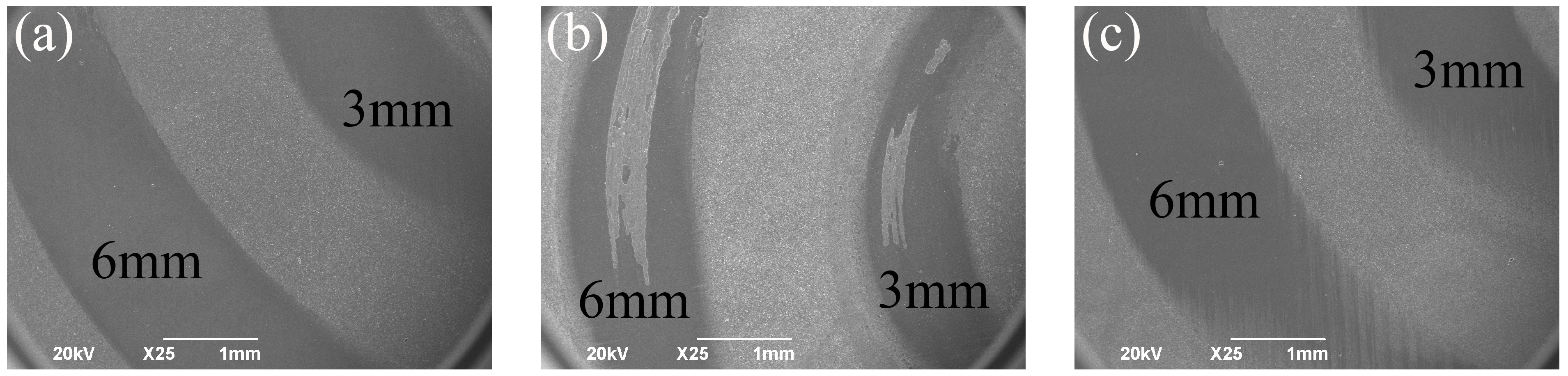
The low-magnified SEM images for the wear morphology of different CrAlN-based gradient multilayer coatings are presented in Figure 6. The wear morphologies of 1-CrN/CrAlN and 3-CrAlN coatings were similar, with smooth and glossy wear channel surfaces and a few unobvious furrow wears. The wear resistance of the 2-CrAl/CrAlN coating was significantly inferior to the 1-CrN/CrAlN and 3-CrAlN coatings, which shows visible coatings peeled off. The wear morphologies of 1-CrN/CrAlN and 2-CrAl/CrAlN with a wear diameter of 6 mm were selected for further composition and morphology analysis.
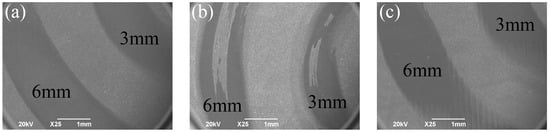
Figure 6.
Low-magnified wear morphology of 1-CrN/CrAlN (a), 2-CrAl/CrAlN (b), and 3-CrAlN (c) gradient multilayer coatings.
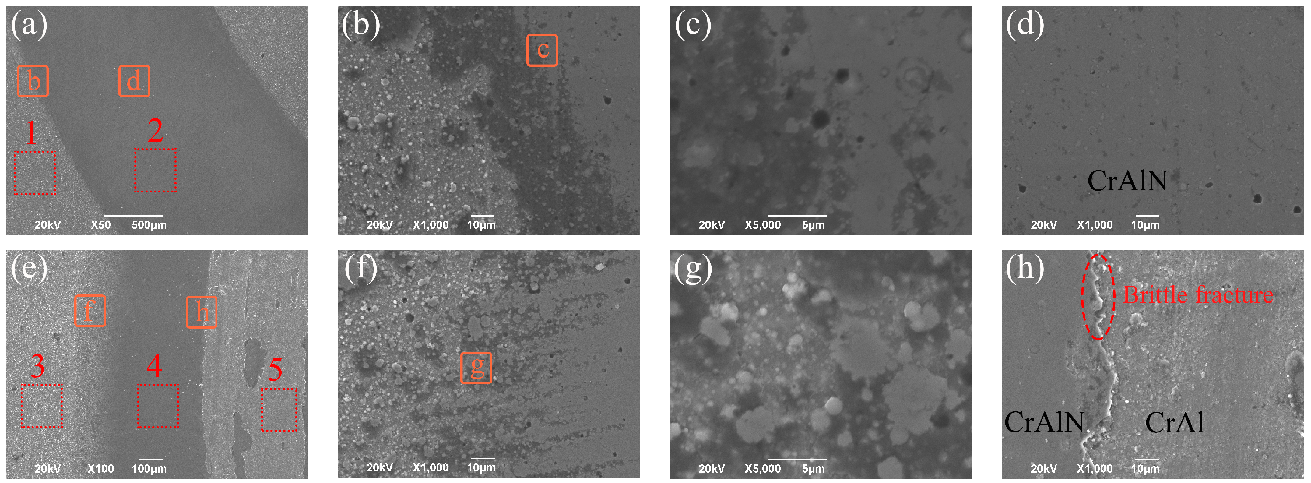
The wear morphology of 1-CrN/CrAlN and 2-CrAl/CrAlN gradient multilayer coatings at a 6 mm wear diameter are shown in Figure 7a–d and e–f, respectively. The corresponding elemental contents (at %) of the marked labels in Figure 7 are listed in Table 3. As for the 1-CrN/CrAlN coating, the width of the wear mark was about 1600 μm. The enlarged wear area in Figure 7b–d proved that the friction only smoothed the surface by grinding away the large un-melted particles. Therefore, only a small number of micro-pores were found on the coating surface, without grooves, furrows, brittle fractures, and other wear marks. Consequently, the wear mechanism between the 1-CrN/CrAlN coating and Si3N4 balls was mainly sliding wear with a small amount of abrasive wear [23,24]. This was mainly due to the high hardness of the CrAlN coating, which was harder than the wear products and peeled particles. Furthermore, few abrasive wear and adhesive wear were formed because of the less shed particles, demonstrating the characteristics of sliding friction wear.
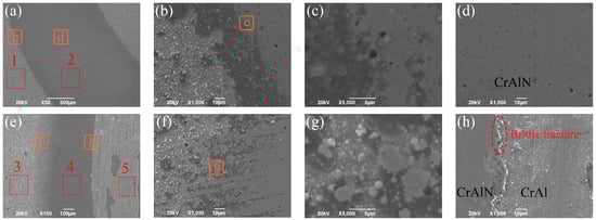
Figure 7.
Wear morphology of 1-CrN/CrAlN (a–d) and 2-CrAl/CrAlN (e–h) gradient multilayer coatings at 6 mm wear diameter.
Table 3.
Elemental contents (at. %) in wear scars from the marked labels in Figure 7.
As shown in Figure 7e–f, the width of the total and middle abrasion marks for the 2-CrAl/CrAlN coating at the same condition was about 1460 μm and 433 μm, respectively. Meanwhile, the distance between the middle abrasion mark and the outer abrasion mark boundary was about 400~600 μm. The edge wear morphology of the 2-CrAl/CrAlN coating was similar to that of the 1-CrN/CrAlN coating, which can be ascribed to their similar CrAlN layer on the surface. However, the obvious coatings that peeled off were detected in the middle of the abrasion mark, which may be due to the brittle fractures or severe adhesive wear during friction caused by the poor adhesion of the 2-CrAl/CrAlN coating.
The EDS results in Table 3 indicate that the main elements on the surface before and after friction were Cr, Al, and N. The detected O element in labels 1 and 3 proved that a small amount of oxides existed on the unworn coating surface. Compared with labels 1 and 3, the O content of labels 2 and 4 after friction was reduced, because the surface oxides were worn away. Lower N and higher O contents were detected in label 5, which were from the wear mark after spalling in the middle of the 2-CrAl/CrAlN coating. This is because of the explosion of the CrAl metal layer when the upper CrAlN layer was worn away, which shows lower N content and has been easily oxidized.
3.3. Characterization of Coated Screws
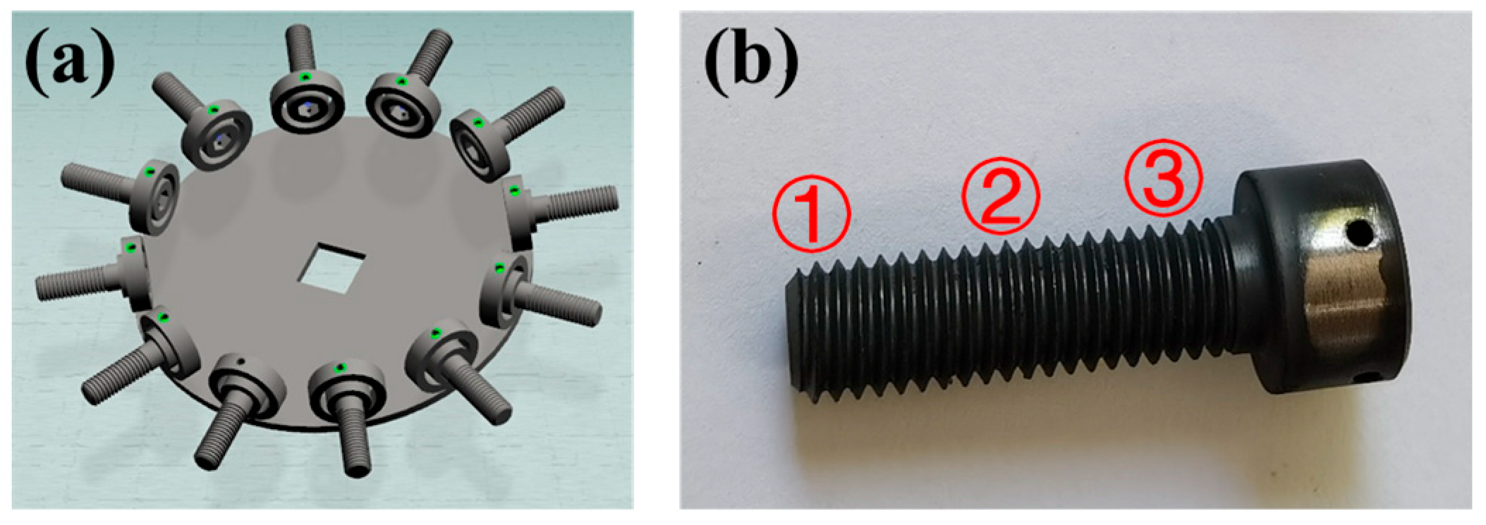
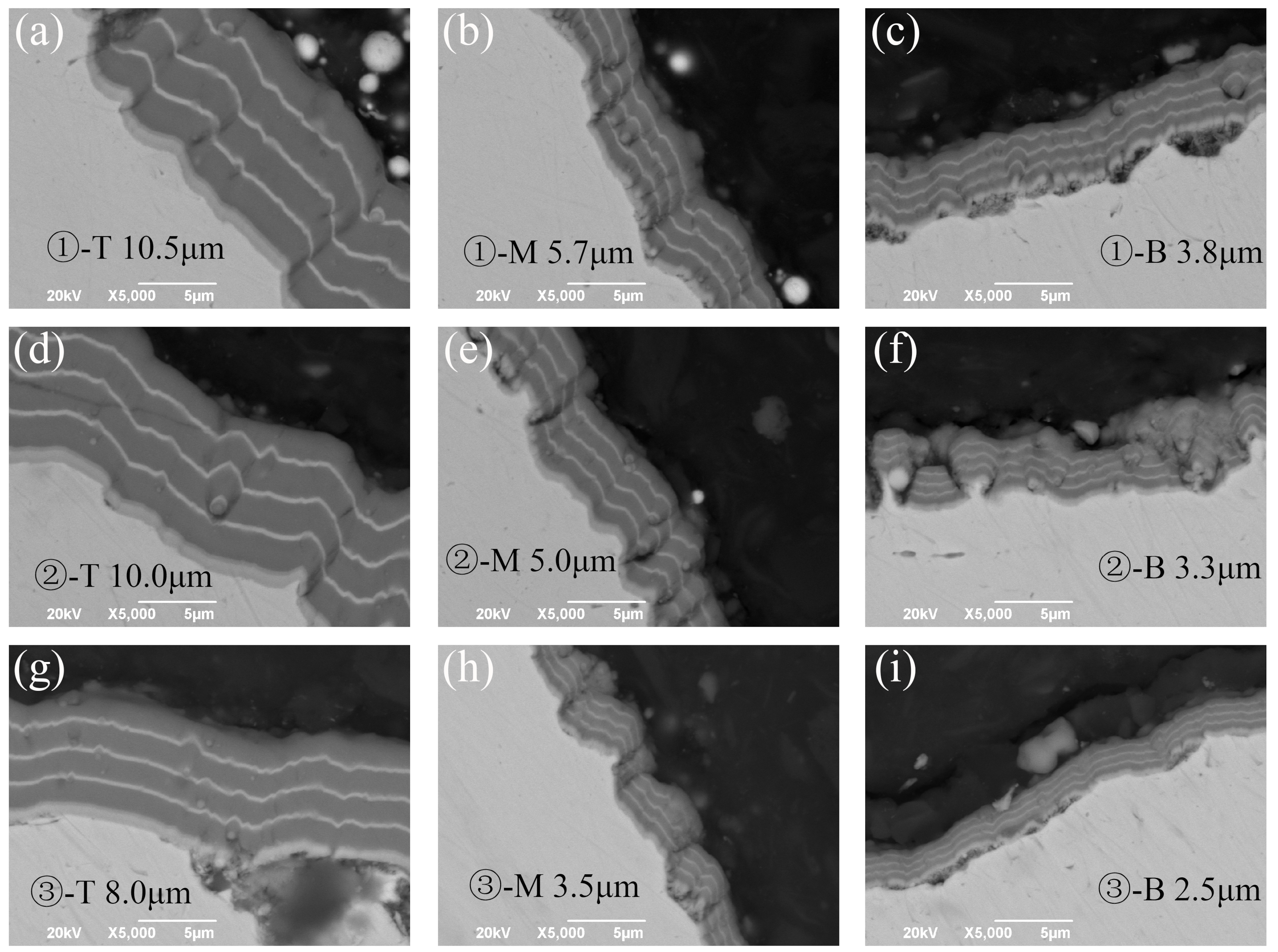
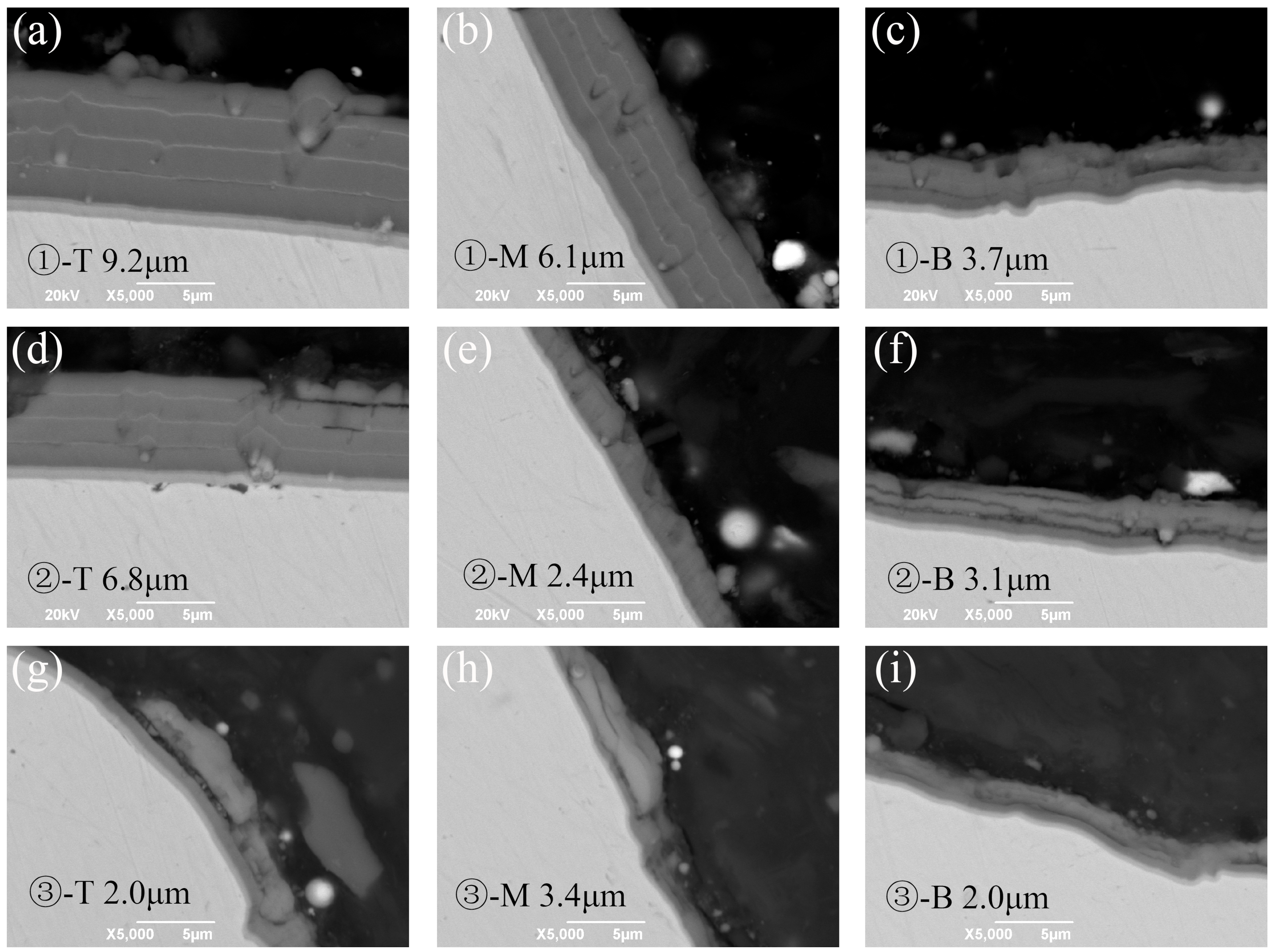
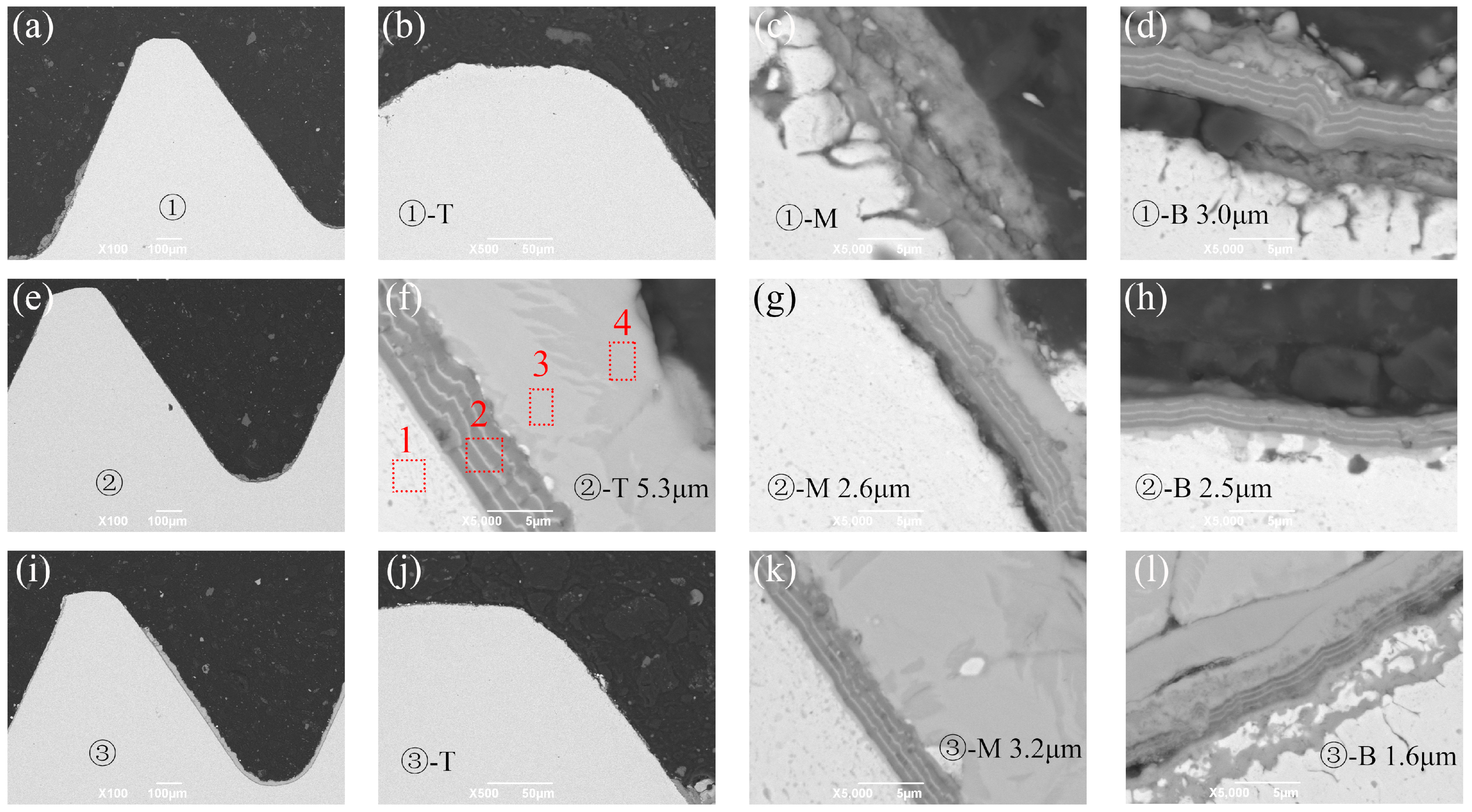
In order to ensure the uniformity of the coating at the circumferential position of the screw, the clamps in Figure 8a were used to carry out the coating deposition on the screws. As shown in Figure 8b, the coating thickness and structure of the threads at the bottom (labeled as ①), middle (labeled as ②), and top (labeled as ③) of the typical coated screws were dissected and analyzed. As for each thread, the coating on the top (labeled as T), middle (labeled as M), and bottom (labeled as B) was characterized. The SEM images of the screw coated with 1-CrN/CrAlN coating and 2-CrAl/CrAlN coating were selected and presented in Figure 9 and Figure 10, respectively.

Figure 8.
Clamping diagram of screw for coating deposition (a) and photograph of a typical coated screw (b).

Figure 9.
Cross-section SEM images of 1-CrN/CrAlN coating deposited on thread top (T, (a,d,g)), thread middle (M, (b,e,h)), and thread bottom (B, (c,f,i)), which are obtained at the screw bottom (①, (a–c)), screw middle (②, (d–f)), and screw top (③, (g–i)) in Figure 8.

Figure 10.
Cross-section SEM images of 2-CrAl/CrAlN coating deposited on thread top (T, (a,d,g)), thread middle (M, (b,e,h)), and thread bottom (B, (c,f,i)), which are obtained at the screw bottom (①, (a–c)), screw middle (②, (d–f)), and screw top (③, (g–i)) in Figure 8.
The SEM images in Figure 9 prove that a similar 1-CrN/CrAlN coating structure was successfully obtained at the screw. The coating thickness at the top, middle, and bottom of the thread was 8.0–10.5 μm, 3.5–5.7 μm, and 2.5–3.8 μm, respectively, indicating that the coating was preferentially deposited on the top of the thread. The thickness difference was related to the clamping method, deposition distance, screw shape, and other factors. For the same thread, the thickness of the thread top was about 2 times that of the thread middle and about 3 times that of the thread bottom. This obvious difference in the coating thickness of the same thread was mainly related to the irregular screw shape. During the deposition process, the ions were more easily deposited on the thread top. Furthermore, as for the same position on the thread, the coating thickness slightly decreased from the screw bottom (①) to the screw top (③). This small difference in the coating thickness of the screws along their length was ascribed to the deposition distance difference caused by the clamping method. As shown in Figure 8, the farther the nut is from the target, the greater the deposition distance, so the coating is slightly thinner. In addition, the screw in Figure 9 was blackening treated and acid washed. Therefore, the adhesion and quality of the coating was affected by the obvious roughness and impurities on the surface, leading to the uneven coating surface. In general, the coating thickness decreased from the screw bottom (①) to screw top (③) and from the thread top to the thread bottom.
Figure 10 shows that a similar 2-CrAl/CrAlN coating structure was also successfully prepared at the screw. The overall variation of the coating thickness was similar to that of the 1-CrN/CrAlN coating in Figure 9. However, an anomaly thickness of only 2 μm was detected at the thread top in Figure 10g, which was due to the coating delamination peeling caused by the poor adhesion of the 2-CrAl/CrAlN coating. Furthermore, the surface finish of both the screw and the coating in Figure 10 were smoother than that in Figure 9, which proves that the coating morphology was strongly dependent on the surface state of the screw.
3.4. Simulation Service Analysis of Screws
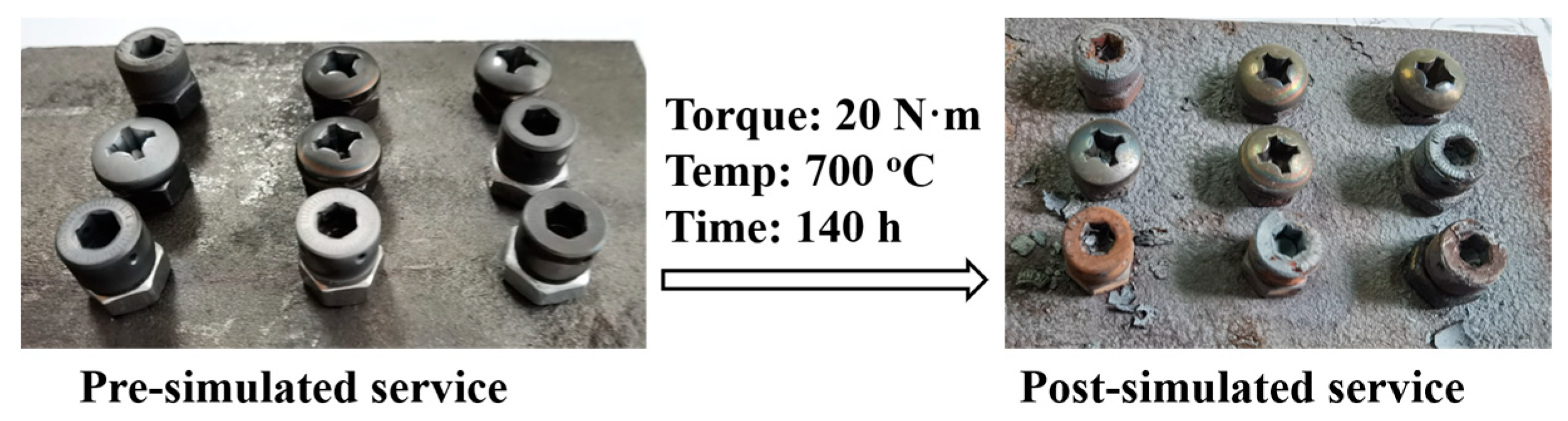
To speed up the high-temperature, anti-seizing performance evaluation, the coated screws were heated to 700 °C for 140 h with a torque of 20 N·m. The pre- and post-simulated service photos of different screws coated with different CrAlN-based gradient multilayer coatings are shown in Figure 11. The results indicate that, although the oxidation time was only 140 h, a large amount of oxide-scale formed on the surface of the screws due to the heating temperature up to 700 °C. To evaluate the anti-seizing performance of the coating, the coated screws, after the simulated service, were dismounted and dissected. The anti-seizing performance was qualitatively estimated by the ease of screw dismounting, the thread integrity, and the residual amount of the coating. The screw removal results indicate that, for the screws with different materials, better material properties lead to easier removal. Meanwhile, the smoother the surface of the screw, the less surface oxide, and the better adhesion, the easier it will be to remove the screw. For the same kind of screw, 1-CrN/CrAlN- and 3-CrAlN-coated screws were easier to remove than 2-CrAl/CrAlN-coated screws.
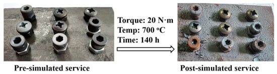
Figure 11.
The pre- and post-simulated service photos of different screws coated with different CrAlN-based gradient multilayer coatings.
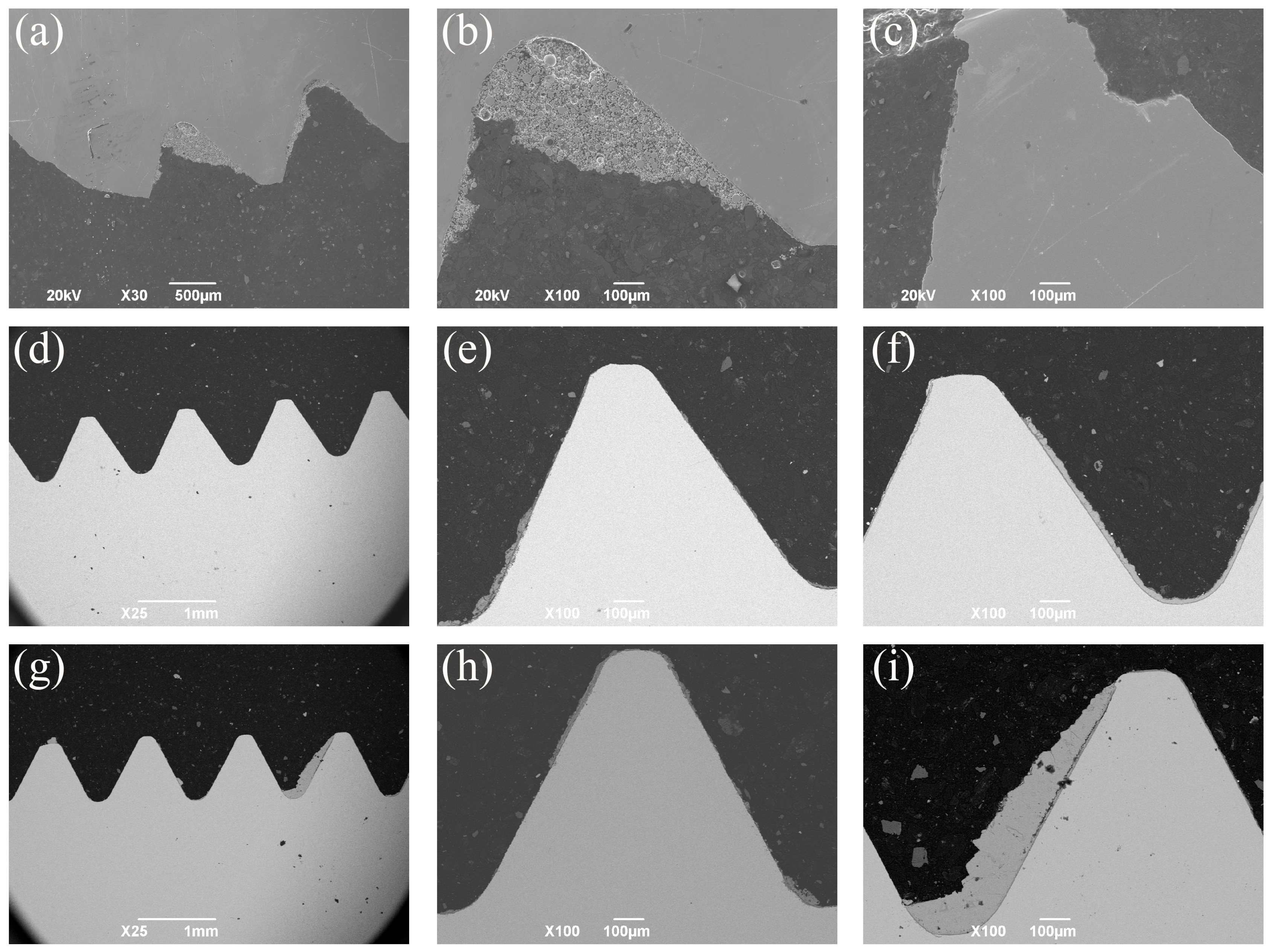
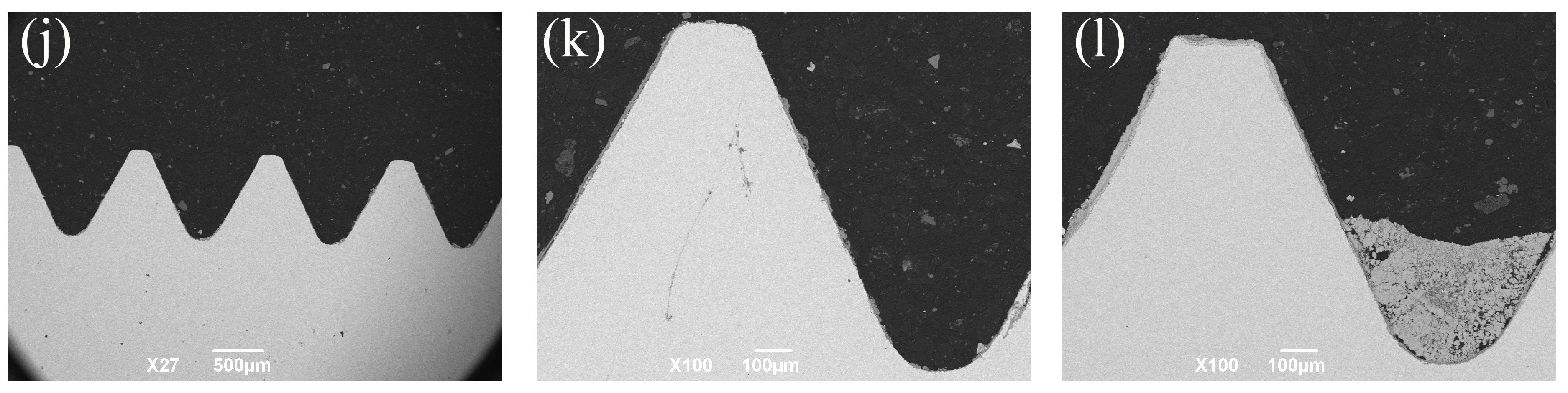
As shown in Figure 12a–c, there are obvious missing and broken threads, oxide scales from the matched internal thread, and serious seizures were found on the uncoated screws after the simulated service. The low-magnified SEM images of 1-CrN/CrAlN-, 2-CrAl/CrAlN-, and 3-CrAlN-coated screws after the simulated service are shown in Figure 12d–f, g–i, and j–l, respectively. The SEM images prove that, although the screws were coated with different CrAlN coatings, most of the coated thread remains intact. The results indicate that a CrAlN coating can improve the anti-seizing performance of the screw. Furthermore, a large area of residues from the matched internal thread were detected on the 2-CrAl/CrAlN- (Figure 12i) and 3-CrAlN-coated screws (Figure 12l). Therefore, the 1-CrN/CrAlN-coated screws exhibited better anti-seizing property due to the better performance of the 1-CrN/CrAlN coatings (Figure 12d–f). To further analyze the influence of substrates on the anti-seizing property of screws, the 1-CrN/CrAlN coating was deposited, and the simulated service on the screws were made of different substrates.


Figure 12.
Low-magnified SEM images of same screws after simulated service, which were uncoated (a–c) and coated with 1-CrN/CrAlN (d–f), 2-CrAl/CrAlN (g–i), and 3-CrAlN (j–l) gradient multilayer coatings.
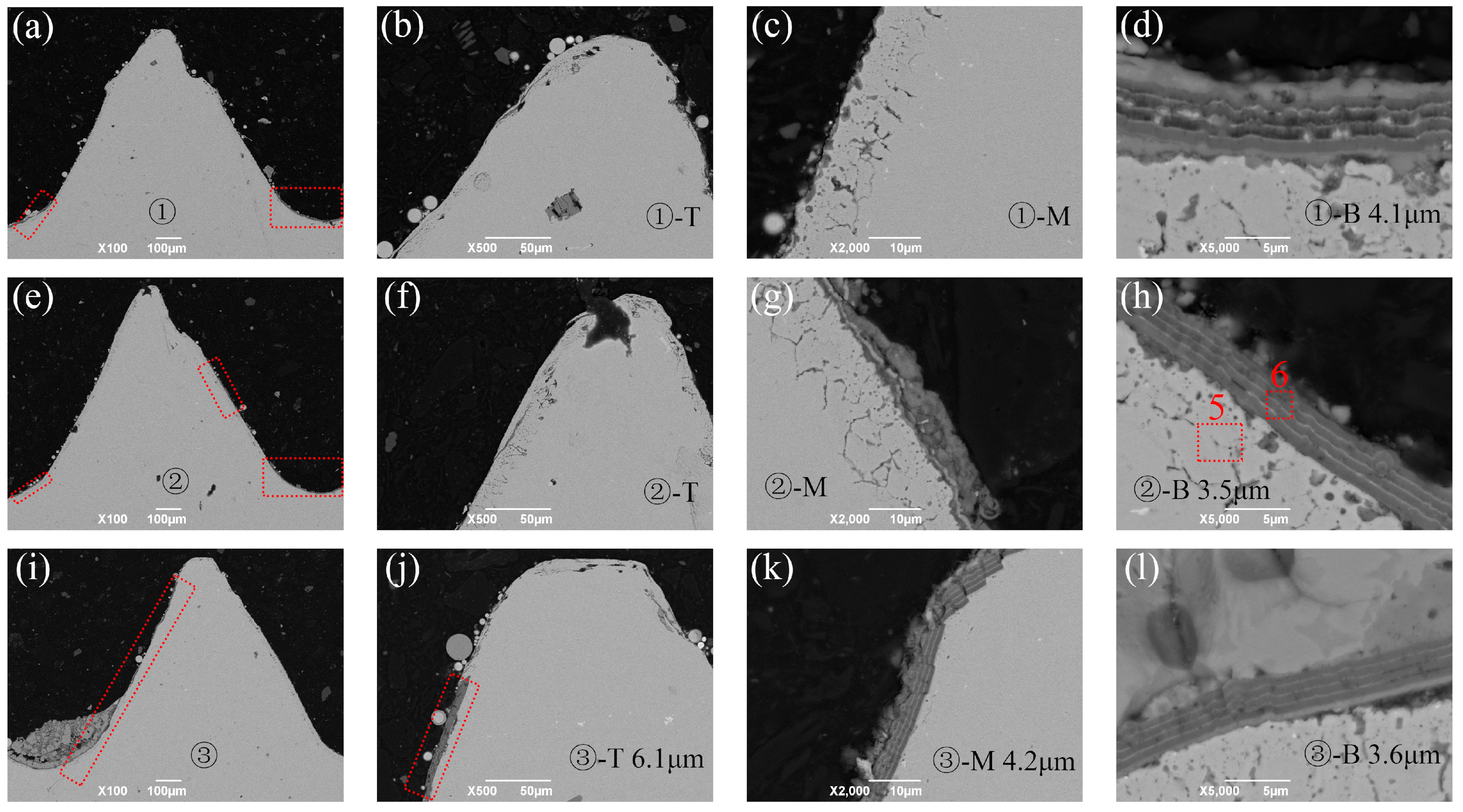
The SEM images of the 1-CrN/CrAlN-coated screws after the simulated service are presented in Figure 13, which were made of stainless steel. The overall structure of the screw was complete due to the good oxidation resistance of stainless-steel substrate. Although most of the coating on the top of the thread was completely peeled off, the thickness of thickest remaining coating was 5.3 μm (Figure 13f). The elemental contents (at. %) of the marked labels in Figure 13f are shown in Table 4. The label 1 mainly consisted of Fe, Cr, Ni, and Cu elements, which were from the screw substrate. The absence of a significant O element was also evidence of the low oxidation of the screw substrate. The main elements of the coating labeled 2 after the simulated service were Cr, Al, and N, which were similar to the as-prepared coating. Furthermore, the detection of a small amount of O and Fe proved the oxidation and diffusion during heating. The labels 3 and 4 were mainly made of Fe and O elements, indicating that the internal thread fit on the other end was heavily oxidized. Many residual coatings were detected in the middle and bottom of the threads, whose structure was also similar to the as-prepared coating with a thickness of about 2~3 μm.
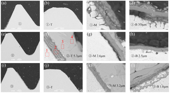
Figure 13.
Cross-section SEM images of 1-CrN/CrAlN coating deposited on thread top (T, (b,f,j)), thread middle (M, (c,g,k)), and thread bottom (B, (d,h,l)), which are obtained at the bottom (①, (a–d)), middle (②, (e–h)), and top (③, (i–l)) of the screw made of stainless steel (Figure 8).
The SEM images of the 1-CrN/CrAlN-coated screws after the simulated service are presented in Figure 14, which were made of heat-resistant steel. The morphology and structure of the heated screws made of heat-resistant steel were similar to that of stainless steel. However, the temperature was too high to cause obvious oxidation of the heat-resistant steel, leading to surface oxide layers up to 10 μm thick and the decrease of coating adhesion. As shown in Figure 14a,e,g,i, the remained coatings were marked with red box. Furthermore, deformation and a small amount of missing appeared in the middle and upper part of the screws. The structural integrity of this screw was better than that of the uncoated screw with same material in Figure 12a–c but worse than that of the same 1-CrN/CrAlN-coated screw with better material in Figure 13. Less coating residue was detected and marked with dotted boxes in Figure 14, whose structure and thickness were similar to that of the coated stainless steel in Figure 14. As shown in Table 4, the screw substrate in Figure 14h (label 5) mainly consists of Fe, Cr, Al, and O elements. A large number of O elements also proved the serious oxidation of the heat-resistant steel. The coating composition after the simulated service (label 6) was similar to label 2, which consisted of a large number Cr, Al, and N elements and a small amount of O and Fe elements. The above results prove that, although the oxidation resistance of the coating reaches 700 °C, the poor oxidation resistance of the substrate leads to the oxidation of the substrate and peeling off of the coating.
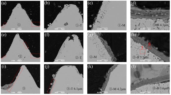
Figure 14.
Cross-section SEM images of 1-CrN/CrAlN coating deposited on thread top (T, (b,f,j)), thread middle (M, (c,g,k)), and thread bottom (B, (d,h,l)), which are obtained at the bottom (①, (a–d)), middle (②, (e–h)), and top (③, (i–l)) of the screw made of heat-resistant steel (Figure 8).
The EDS line scan results of the 1-CrN/CrAlN coating obtained on the substrate, as-prepared screw, and screw after the simulated service are shown in Figure 15a, Figure 15b, and Figure 15c, respectively. Figure 15a,b indicate that the as-prepared 1-CrN/CrAlN coating on the substrate and screw exhibited similar elemental distribution. The obvious strength differences between Al and Cr elements also prove that the thick and dark layer was the CrAlN layer while the thin and bright layer was the CrN layer. Compared with the as-prepared coating, the Fe elements from the substrate diffused into the coating after the simulated service. Furthermore, the O element distribution proves the oxidation on the surface of the coating and at the interface between the coating and substrate.
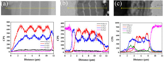
Figure 15.
EDS line scan results of 1-CrN/CrAlN coating obtained on substrate (a), as-prepared screw (b), and screw after simulated service (c).
There are few references about the analysis and evaluation of anti-seizing properties of the coated screw. The Ag–Pd alloy coating provided by Kwon et al. [3] was suitable for the stud bolt working below 393 °C. The Mo/DLC multilayer coating prepared by Kashyap et al. [8] was only applicable to fasteners working below 300 °C. Croccolo et al. [1] and Thompson et al. [7] did not mention the screw’s simulated service test temperature in their work.
In general, the comprehensive properties of the 1-CrN/CrAlN coating were better, which meet the demand of high-temperature, anti-seizing applications. However, in order to further achieve long-term, stable applications, the adhesion should be further improved by adjusting the composition and hardness through Ar and N2 flows and the ratio and number of CrN/CrAlN layers in the future.
4. Conclusions
In summary, the morphology, composition, structure, nano hardness, adhesion, residual stress, and room temperature tribological performance of three different CrAlN-based gradient multilayer coatings were investigated. The 1-CrN/CrAlN coating exhibited better comprehensive properties. The nano-hardness, adhesion strength, and the residual stress of the 1-CrN/CrAlN coatings were 22.8 ± 2.7 GPa, 29.0 ± 1.0 N, and −0.41 GPa (compressive stress), respectively. The wear mechanism between the 1-CrN/CrAlN coating and Si3N4 balls was mainly sliding wear with a small amount of abrasive wear. The results proved that the coating structures obtained on the screws were similar to the flat samples. However, the as-prepared coating on the screws showed different thickness variation rules, which were related to the clamping method, deposition distance, and screw shape. The high-temperature, anti-seizing performance of a screw is closely related to the oxidation resistance of both the substrate and the coatings. After the simulation service, the thread of the screw remains intact with a similar structure but thinner thickness. Therefore, the high-temperature seize prevention of fasteners for gas turbines can be achieved by preparing a CrAlN-based multilayer coating, which is suitable for fasteners with service temperatures below 700 °C.
Author Contributions
Conceptualization, Y.F. and X.G. (Xiufang Gong); methodology, D.L. and W.W.; investigation, C.T., X.Y., X.G. (Xianping Guo) and Q.L.; writing—original draft, C.T.; writing—review and editing, C.T. and D.L. All authors have read and agreed to the published version of the manuscript.
Funding
This research was funded by the Sichuan Science and Technology Program, grant numbers 2023JDRC0063 and 2022SZY002Z, and the National Science and Technology Major Project, grant number 2019-VII-0007-0147.
Data Availability Statement
The original contributions presented in the study are included in the article, further inquiries can be directed to the corresponding author.
Conflicts of Interest
All authors were employed by the company State Key Laboratory of Clean and Efficient Turbomachinery Power Equipment, Dongfang Turbine Co., Ltd. The authors declare no conflicts of interest.
References
- Croccolo, D.; De Agostinis, M.; Fini, S.; Olmi, G. Tribological properties of bolts depending on different screw coatings and lubrications: An experimental study. Tribol. Int. 2017, 107, 199–205. [Google Scholar] [CrossRef]
- Park, C.; Kim, H.-S.; Chung, W.-H.; Kim, J.-H. Validation of cyanide copper electrodeposited layer on test coupons for anti-seizing and outgassing in Tokamak vacuum vessel. Fusion Eng. Des. 2019, 146, 2598–2602. [Google Scholar] [CrossRef]
- Kwon, J.-D.; Lee, S.; Lee, K.-H.; Rha, J.-J.; Nan, K.-S.; Kwon, S.-H. Lubrication properties of silver-palladium alloy prepared by ion plating method for high temperature stud bolt. Trans. Nonferrous Met. Soc. China 2011, 21, S12–S16. [Google Scholar] [CrossRef]
- Kwon, J.-D.; Lee, S.-H.; Lee, K.-H.; Rha, J.-J.; Nam, K.-S.; Choi, S.-H.; Lee, D.-M.; Kim, D.-I. Silver-palladium alloy deposited by DC magnetron sputtering method as lubricant for high temperature application. Trans. Nonferrous Met. Soc. China 2009, 19, 1001–1004. [Google Scholar] [CrossRef]
- Jojith, R.; Sam, M.; Radhika, N. Recent advances in tribological behavior of functionally graded composites: A review. Eng. Sci. Technol. Int. J. 2022, 25, 100999. [Google Scholar] [CrossRef]
- Kakulite, K.K.; Kandasubramanian, B. Rudiment of ‘galling: Tribological phenomenon’ for engineering components in aggregate with the advancement in functioning of the anti-galling coatings. Surf. Interfaces 2019, 17, 100383. [Google Scholar] [CrossRef]
- Thompson, V.; Eaton, R.; Raffray, R.; Egorov, K. Properties of low friction anti-seize coatings for fusion applications. Fusion Eng. Des. 2019, 146, 345–348. [Google Scholar] [CrossRef]
- Kashyap, A.; Harsha, A.P.; Kondaiah, P.; Barshilia, H.C. Study on galling behaviour of HiPIMS deposited Mo/DLC multilayer coatings at ambient and elevated temperature. Wear 2022, 498–499, 204327. [Google Scholar] [CrossRef]
- Sathish, M.; Radhika, N.; Saleh, B. A critical review on functionally graded coatings: Methods, properties, and challenges. Compos. Part B Eng. 2021, 225, 109278. [Google Scholar] [CrossRef]
- Akrami, S.; Edalati, P.; Fuji, M.; Edalati, K. High-entropy ceramics: Review of principles, production and applications. Mater. Sci. Eng. R Rep. 2021, 146, 100644. [Google Scholar] [CrossRef]
- Bai, H.; Zhong, L.; Kang, L.; Liu, J.; Zhuang, W.; Lv, Z.; Xu, Y. A review on wear-resistant coating with high hardness and high toughness on the surface of titanium alloy. J. Alloys Compd. 2021, 882, 160645. [Google Scholar] [CrossRef]
- Krella, A. Resistance of PVD Coatings to Erosive and Wear Processes: A Review. Coatings 2020, 10, 921. [Google Scholar] [CrossRef]
- Wang, D.; Lin, S.-S.; Tian, T.; Liu, M.-X.; Chang, G.-R.; Dong, D.; Shi, J.; Dai, M.-J.; Jiang, B.-L.; Zhou, K.-s. Sand erosion and crack propagation mechanism of Cr/CrN/Cr/CrAlN multilayer coating. Ceram. Int. 2022, 48, 24638–24648. [Google Scholar] [CrossRef]
- Ruan, H.; Wang, Z.; Wang, L.; Sun, L.; Peng, H.; Ke, P.; Wang, A. Designed Ti/TiN sub-layers suppressing the crack and erosion of TiAlN coatings. Surf. Coat. Technol. 2022, 438, 128419. [Google Scholar] [CrossRef]
- Zhang, M.; Li, Y.; Feng, Y.; Xin, L.; Niu, Y.; Su, J.; Zhu, S.; Wang, F. Studies on different oxidation behaviors of TiAlN on titanium alloy and stainless steel under thermal cycling. Corros. Sci. 2021, 192, 109865. [Google Scholar] [CrossRef]
- He, J.; Lan, X.; Liu, Z.; Jiao, D.; Zhong, X.; Cheng, Y.; Tang, C.; Qiu, W. Modification of Cr/CrN composite structure by Fe addition and its effect on decorative performance and corrosion resistance. Ceram. Int. 2021, 47, 23888–23894. [Google Scholar] [CrossRef]
- Liew, W.Y.H.; Lim, H.P.; Melvin, G.J.H.; Dayou, J.; Jiang, Z.-T. Thermal stability, mechanical properties, and tribological performance of TiAlXN coatings: Understanding the effects of alloying additions. J. Mater. Res. Technol. 2022, 17, 961–1012. [Google Scholar] [CrossRef]
- Bonu, V.; Jeevitha, M.; Praveen Kumar, V.; Srinivas, G.; Siju; Barshilia, H.C. Solid particle erosion and corrosion resistance performance of nanolayered multilayered Ti/TiN and TiAl/TiAlN coatings deposited on Ti6Al4V substrates. Surf. Coat. Technol. 2020, 387, 125531. [Google Scholar] [CrossRef]
- Guo, H.; Sun, Q.; Zhou, D.; Yu, M.; Wang, Y.; Wang, Q.; Li, X. Erosion behavior of CrN, CrAlN and CrAlN/CrN multilayer coatings deposited on Ti6Al4V. Surf. Coat. Technol. 2022, 437, 128284. [Google Scholar] [CrossRef]
- Li, C.; Wang, L.; Shang, L.; Cao, X.; Zhang, G.; Yu, Y.; Li, W.; Zhang, S.; Hu, H. Mechanical and high-temperature tribological properties of CrAlN/TiSiN multilayer coating deposited by PVD. Ceram. Int. 2021, 47, 29285–29294. [Google Scholar] [CrossRef]
- Guo, C.Q.; Pei, Z.L.; Fan, D.; Liu, R.D.; Gong, J.; Sun, C. Predicting multilayer film’s residual stress from its monolayers. Mater. Des. 2016, 110, 858–864. [Google Scholar] [CrossRef]
- Reiter, A.E.; Derflinger, V.H.; Hanselmann, B.; Bachmann, T.; Sartory, B. Investigation of the properties of Al1−xCrxN coatings prepared by cathodic arc evaporation. Surf. Coat. Technol. 2005, 200, 2114–2122. [Google Scholar] [CrossRef]
- Zhang, X.; Tian, X.; Gong, C.; Liu, X.; Li, J.; Zhu, J.; Lin, H. Effect of plasma nitriding ion current density on tribological properties of composite CrAlN coatings. Ceram. Int. 2022, 48, 3954–3962. [Google Scholar] [CrossRef]
- Al-Asadi, M.M.; Al-Tameemi, H.A. A review of tribological properties and deposition methods for selected hard protective coatings. Tribol. Int. 2022, 176, 107919. [Google Scholar] [CrossRef]

Disclaimer/Publisher’s Note: The statements, opinions and data contained in all publications are solely those of the individual author(s) and contributor(s) and not of MDPI and/or the editor(s). MDPI and/or the editor(s) disclaim responsibility for any injury to people or property resulting from any ideas, methods, instructions or products referred to in the content. |
© 2024 by the authors. Licensee MDPI, Basel, Switzerland. This article is an open access article distributed under the terms and conditions of the Creative Commons Attribution (CC BY) license (https://creativecommons.org/licenses/by/4.0/).