
Grain Refinement and Mechanical Enhancement of Titanium Matrix Composites with Nickel-Coated Graphene Nanoflakes: Influence of Particle-Size Mismatch
Abstract
:1. Introduction
2. Experimental Procedures
2.1. Raw Materials
2.2. Surface Coating
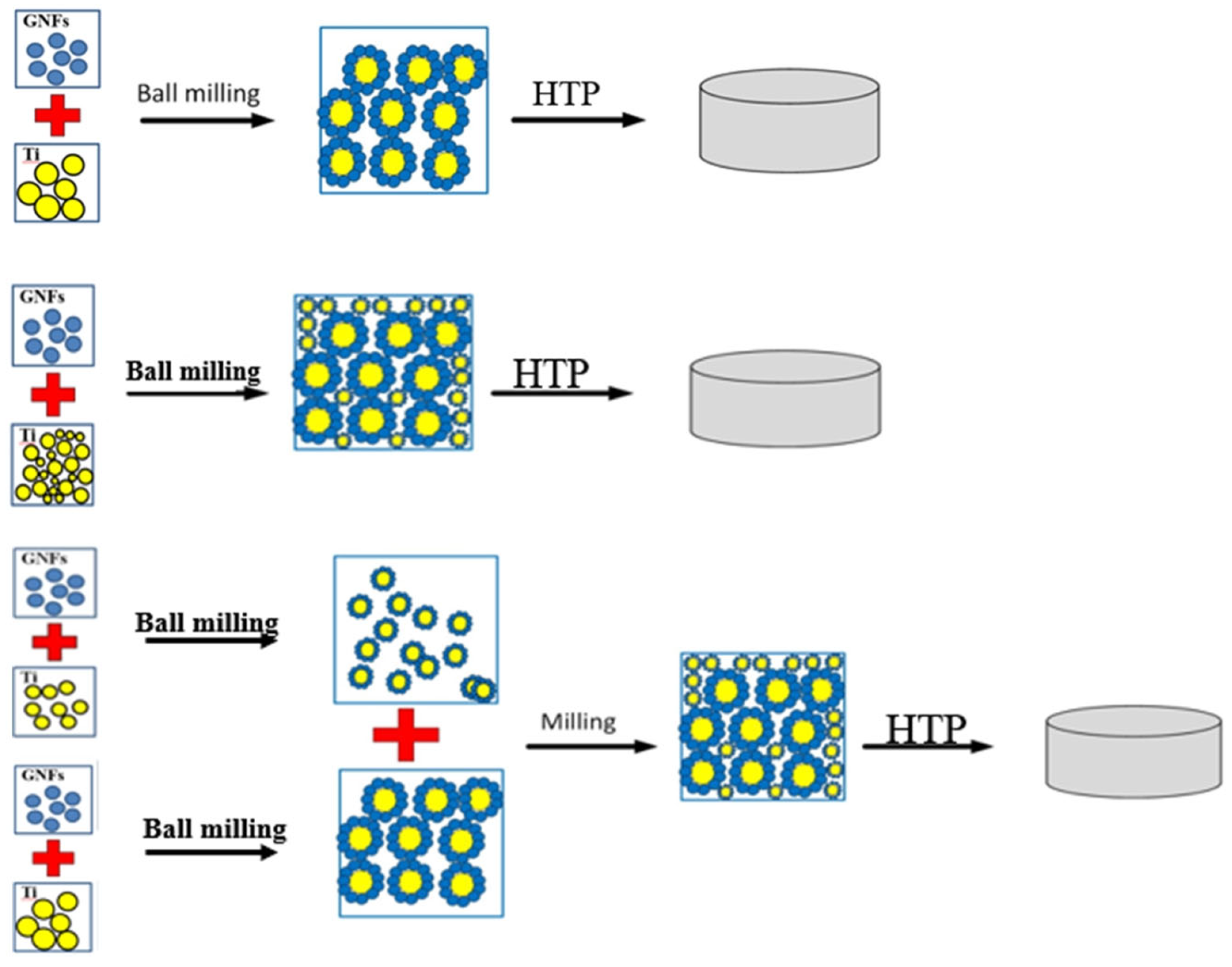
2.3. Preparation of TC4/GNF(Ni) Composites
2.4. Characterization of TC4/GNF(Ni) Composites
3. Results
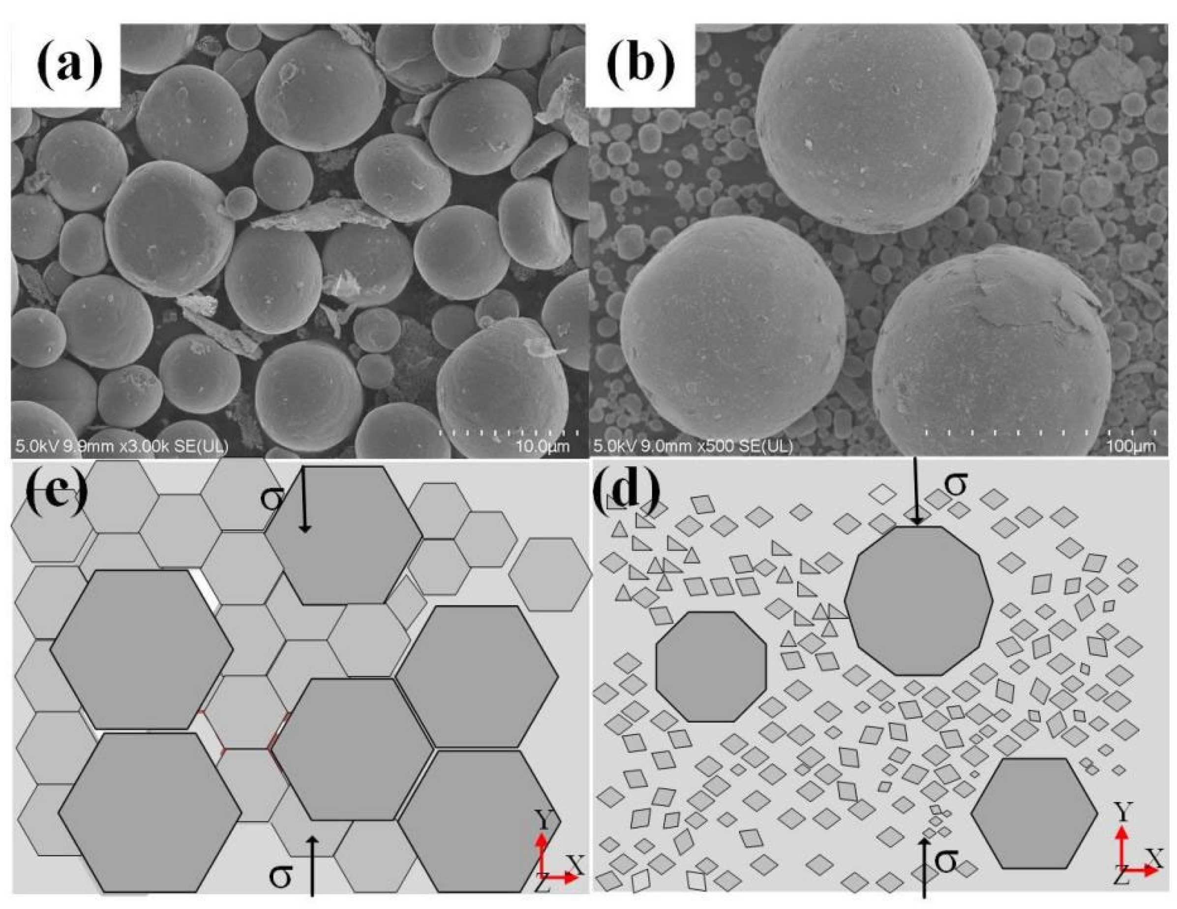
3.1. Characterization of Powder Surface
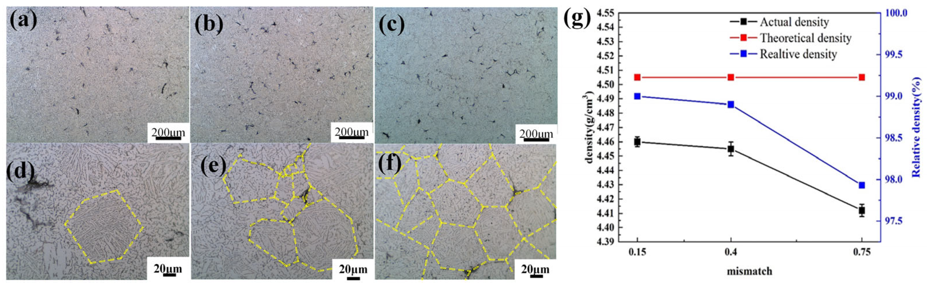
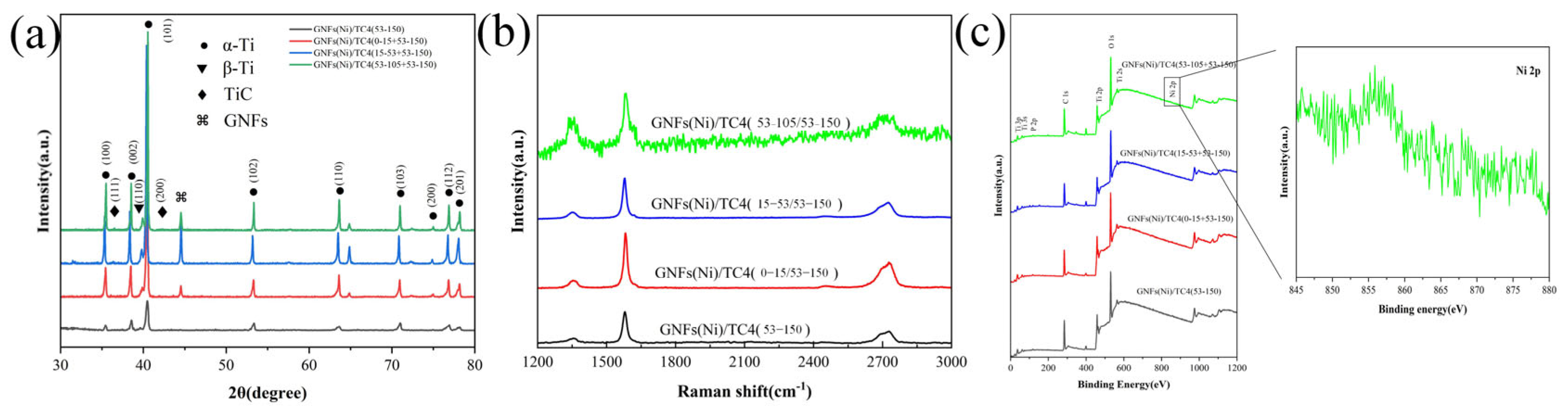
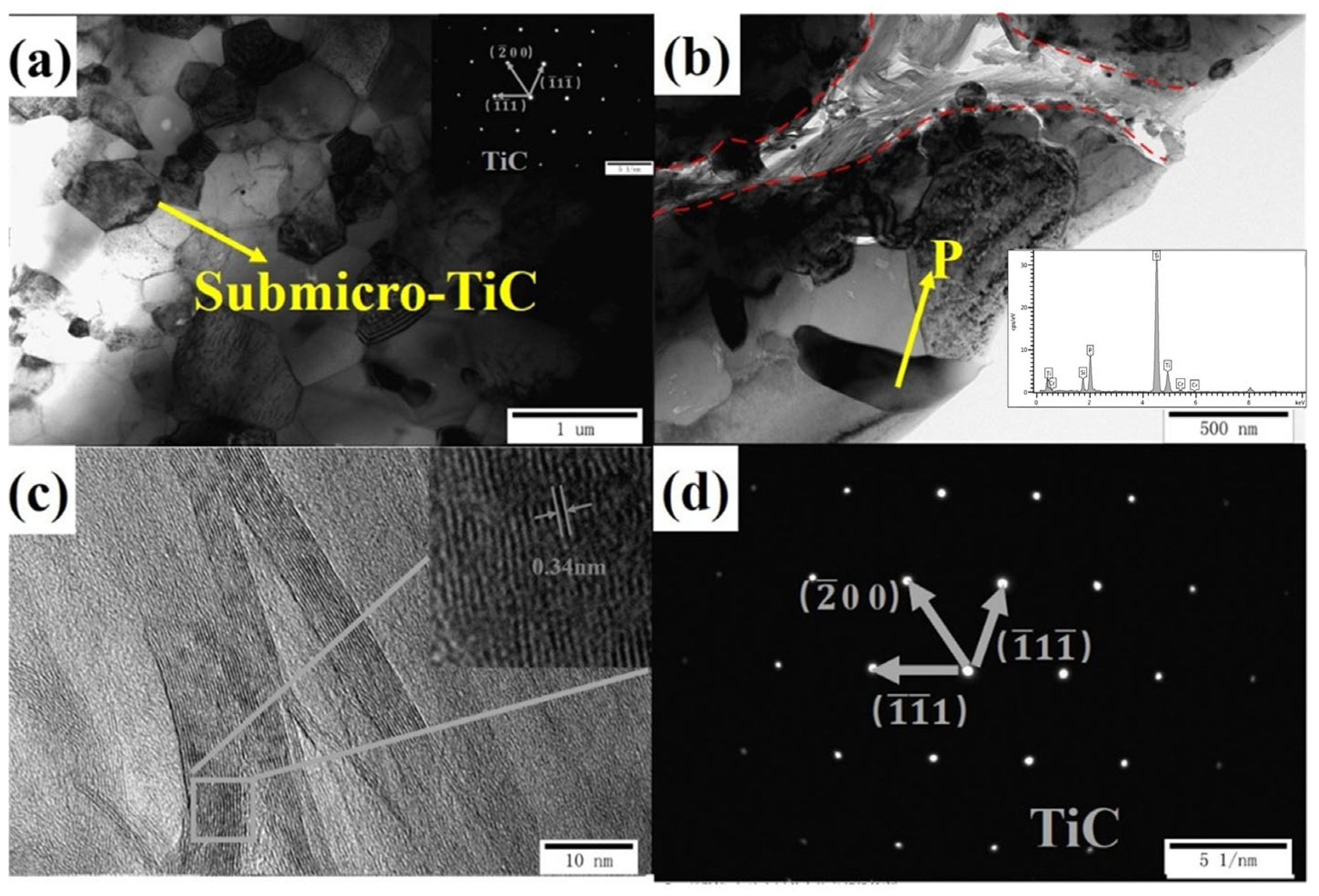
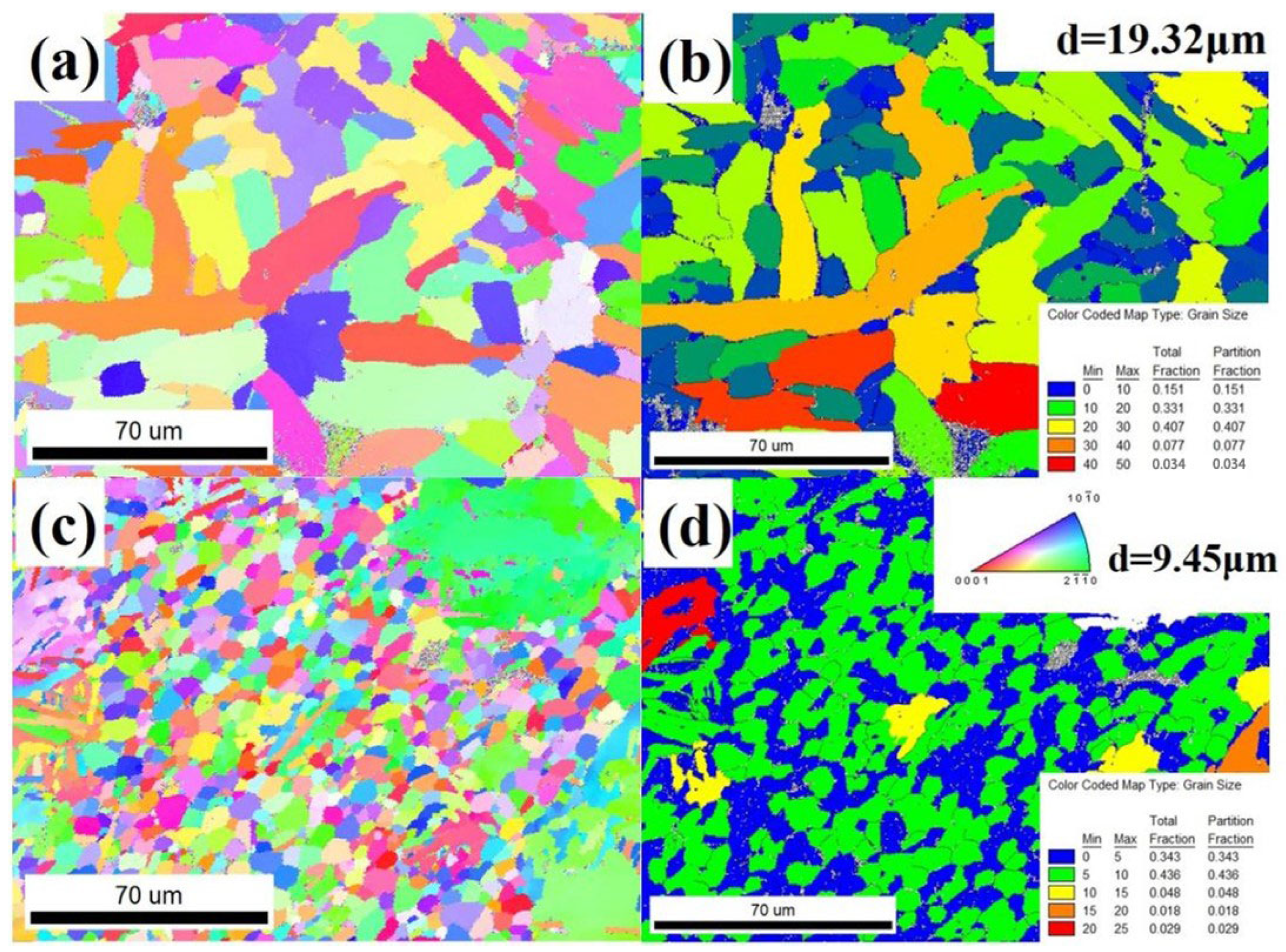
3.2. Characterization of the GNF(Ni)/TC4 Composites
3.3. Mechanical Properties of the GNF(Ni)/TC4 Composites
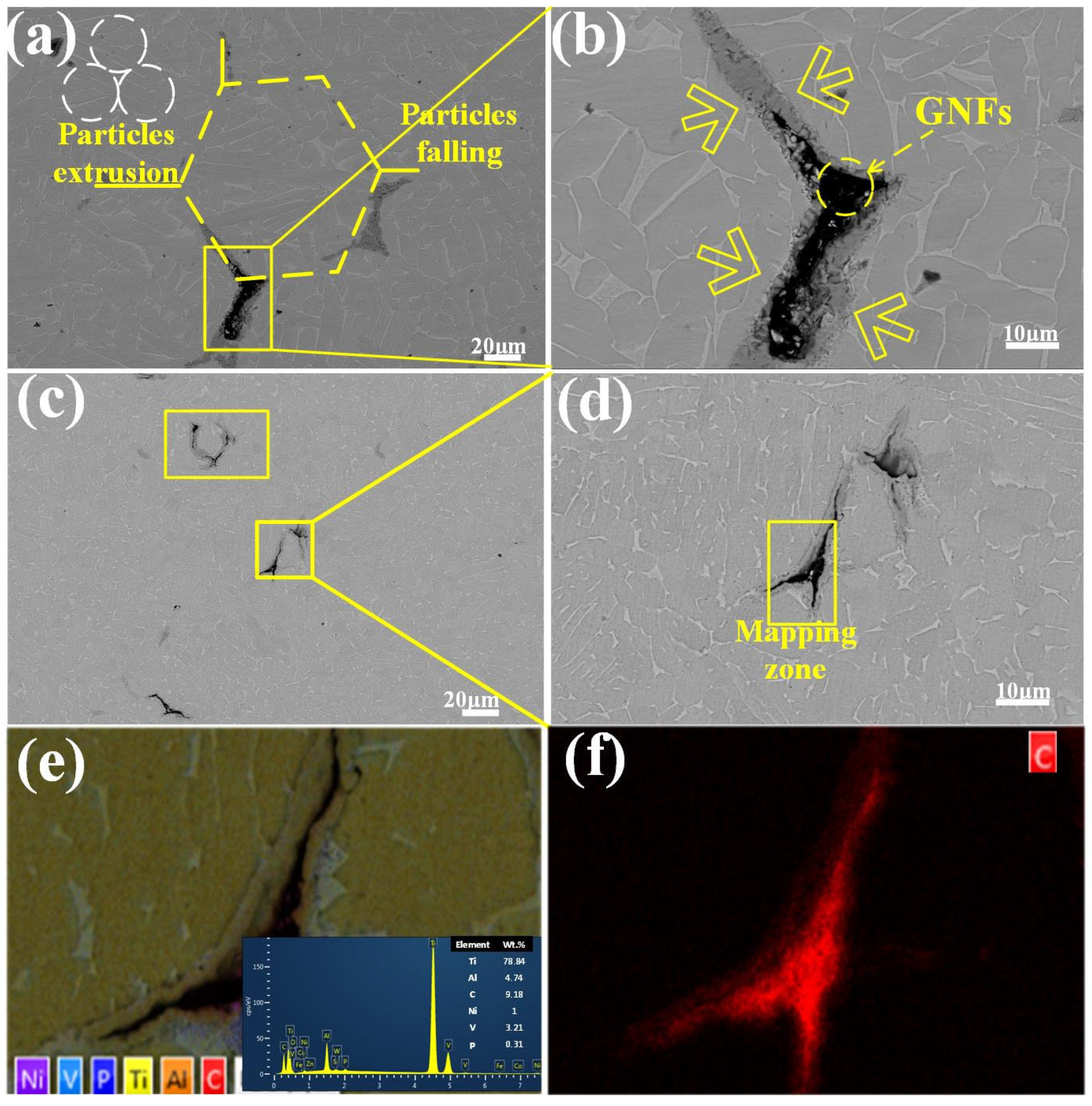
3.4. Fracture Morphology and Crack Propagation
4. Discussion
5. Conclusions
Author Contributions
Funding
Data Availability Statement
Acknowledgments
Conflicts of Interest
References
- Niu, J.; Dai, G.; Guo, Y.; Sun, Z.; Dan, Z.; Dong, Y.; Chang, H.; Alexandrov, I.V.; Zhou, L. Microstructure and mechanical properties of B modified Ti–Fe alloy manufactured by casting, forging and laser melting deposition. Compos. Part B Eng. 2021, 216, 108854. [Google Scholar] [CrossRef]
- Zhang, F.; Liu, T. Nanodiamonds reinforced titanium matrix nanocomposites with network architecture. Compos. Part B Eng. 2019, 165, 143–154. [Google Scholar] [CrossRef]
- Zhou, Y.; Dong, L.; Yang, Q.; Huo, W.; Fu, Y.; Yu, J.; Liu, Y.; Zhang, Y. Controlled Interfacial Reactions and Superior Mechanical Properties of High Energy Ball Milled/Spark Plasma Sintered Ti-6Al-4V-Graphene Composite. Adv. Eng. Mater. 2021, 23, 2001411. [Google Scholar] [CrossRef]
- Fattah-alhosseini, A.; Molaei, M.; Nouri, M.; Babaei, K. Review of the role of graphene and its derivatives in enhancing the performance of plasma electrolytic oxidation coatings on titanium and its alloys. Appl. Surf. Sci. Adv. 2021, 6, 100140. [Google Scholar] [CrossRef]
- Liu, Y.; Liang, C.; Liu, W.; Ma, Y.; Liu, C.; Zhang, C. Dilution of Al and V through laser powder deposition enables a continuously compositionally Ti/Ti6Al4V graded structure. J. Alloys Compd. 2018, 763, 376–383. [Google Scholar] [CrossRef]
- Meng, X.; Min, J.; Sun, Z.G.; Zhang, W.S.; Chang, H.; Han, Y.F. Columnar to equiaxed grain transition of laser deposited Ti6Al4V using nano-sized B4C particles. Compos. Part B-Eng. 2021, 212, 108667. [Google Scholar] [CrossRef]
- Tang, Y.; Yang, X.; Wang, R.; Li, M. Enhancement of the mechanical properties of graphene–copper composites with graphene–nickel hybrids. Mater. Sci. Eng. A 2014, 599, 247–254. [Google Scholar] [CrossRef]
- Gangwar, K.; Ramulu, M. Friction stir welding of titanium alloys: A review. Mater. Des. 2018, 141, 230–255. [Google Scholar] [CrossRef]
- Li, Y.; Wang, L.; Zhu, L.; Li, Y.; Yan, Z.; Song, Y.; Cheng, X. Investigation of interfacial structure and dynamic mechanical behavior of titanium alloy laminated composites. J. Mater. Res. Technol. 2022, 21, 5111–5120. [Google Scholar] [CrossRef]
- Wu, H.; Huang, M.; Xia, Y.; Li, X.; Li, R.; Liu, C.; Gan, W.; Xiao, T.; Geng, L.; Liu, Q.; et al. The importance of interfacial stress-affected zone in evading the strength-ductility trade-off of heterogeneous multi-layered composites. Int. J. Plast. 2022, 160, 103485. [Google Scholar] [CrossRef]
- Wang, B.; Huang, L.J.; Hu, H.T.; Liu, B.X.; Geng, L. Superior tensile strength and microstructure evolution of TiB whisker reinforced Ti60 composites with network architecture after β extrusion. Mater. Charact. 2015, 103, 140–149. [Google Scholar] [CrossRef]
- Munir, K.S.; Li, Y.; Lin, J.; Wen, C. Interdependencies between graphitization of carbon nanotubes and strengthening mechanisms in titanium matrix composites. Materialia 2018, 3, 122–138. [Google Scholar] [CrossRef]
- Hayat, M.D.; Singh, H.; He, Z.; Cao, P. Titanium metal matrix composites: An overview. Compos. Part A Appl. Sci. Manuf. 2019, 121, 418–438. [Google Scholar] [CrossRef]
- Guo, Y.; Huang, J.; Yu, K.; Dai, G.; Sun, Z.; Chang, H. Effect of the Ti-6Al-4V powder size on the microstructure and mechanical properties of composites with nickel-coated graphene nanoflakes. Mater. Charact. 2022, 184, 111627. [Google Scholar] [CrossRef]
- Liu, L.; Li, Y.; Zhang, H.; Cheng, X.; Mu, X.; Fan, Q.; Ge, Y.; Guo, S. Simultaneously enhancing strength and ductility in graphene nanoplatelets reinforced titanium (GNPs/Ti) composites through a novel three-dimensional interface design. Compos. Part B-Eng. 2021, 216, 108851. [Google Scholar] [CrossRef]
- Yu, K.; Ma, H.; Guo, Y.; Sun, Z.; Dong, Y.; Alexandrov, I.V.; Prokofiev, E.A.; Chang, H. Microstructure evolution and mechanical properties of copper coated graphene nanoflakes/pure titanium matrix composites. Mater. Charact. 2022, 194, 112422. [Google Scholar] [CrossRef]
- Guo, Y.; Yu, K.; Niu, J.; Sun, M.; Dai, G.; Sun, Z.; Chang, H. Effect of reinforcement content on microstructures and mechanical properties of graphene nanoflakes-reinforced titanium alloy matrix composites. J. Mater. Res. Technol. 2021, 15, 6871–6882. [Google Scholar] [CrossRef]
- Qiu, C.; Su, Y.; Yang, J.; Chen, B.; Ouyang, Q.; Zhang, D. Structural modelling and mechanical behaviors of graphene/carbon nanotubes reinforced metal matrix composites via atomic-scale simulations: A review. Compos. Part C Open Access 2021, 4, 100120. [Google Scholar] [CrossRef]
- Yun, C.; Yan, W.; Deng, S.; Gang, C.; Wang, Y.J.C.I. Graphene nanosheets-tungsten oxides composite for supercapacitor electrode. Ceram. Int. 2014, 40, 4109–4116. [Google Scholar] [CrossRef]
- Rashad, M.; Pan, F.; Tang, A.; Asif, M. Effect of Graphene Nanoplatelets addition on mechanical properties of pure aluminum using a semi-powder method. Prog. Nat. Sci. Mater. Int. 2014, 24, 101–108. [Google Scholar] [CrossRef]
- Saba, F.; Zhang, F.; Liu, S.; Liu, T. Reinforcement size dependence of mechanical properties and strengthening mechanisms in diamond reinforced titanium metal matrix composites. Compos. Part B-Eng. 2019, 167, 7–19. [Google Scholar] [CrossRef]
- Long, Y.; Zhang, H.; Wang, T.; Huang, X.; Li, Y.; Wu, J.; Chen, H. High-strength Ti–6Al–4V with ultrafine-grained structure fabricated by high energy ball milling and spark plasma sintering. Mater. Sci. Eng. A 2013, 585, 408–414. [Google Scholar] [CrossRef]
- Kong, F.; Chen, Y.; Zhang, D. Interfacial microstructure and shear strength of Ti–6Al–4V/TiAl laminate composite sheet fabricated by hot packed rolling. Mater. Des. 2011, 32, 3167–3172. [Google Scholar] [CrossRef]
- Liu, B.X.; Huang, L.J.; Rong, X.D.; Geng, L.; Yin, F.X. Bending behaviors and fracture characteristics of laminatedductile-tough composites under different modes. Compos. Sci. Technol. 2016, 126, 94–105. [Google Scholar] [CrossRef]
- Gorelik, M. Additive manufacturing in the context of structural integrity. Int. J. Fatigue 2017, 94, 168–177. [Google Scholar] [CrossRef]
- Wang, S.; Huang, L.; An, Q.; Geng, L.; Liu, B. Dramatically enhanced impact toughness of two-scale laminate-network structured composites. Mater. Des. 2018, 140, 163–171. [Google Scholar] [CrossRef]
- Huang, L.J.; Wang, S.; Geng, L.; Kaveendran, B.; Peng, H.X. Low volume fraction in situ (Ti5Si3+Ti2C)/Ti hybrid composites with network microstructure fabricated by reaction hot pressing of Ti–SiC system. Compos. Sci. Technol. 2013, 82, 23–28. [Google Scholar] [CrossRef]
- Guo, R.; Yu, B.; Shi, X.; Xu, L.; Yang, R. Effect of Powder Size on Fatigue Properties of Ti-6Al-4V Powder Compact Using Hot Isostatic Pressing. JOM 2019, 71, 3614–3620. [Google Scholar] [CrossRef]
- Mu, X.N.; Cai, H.N.; Zhang, H.M.; Fan, Q.B.; Wang, F.C.; Zhang, Z.H.; Ge, Y.X.; Shi, R.; Wu, Y.; Wang, Z.; et al. Uniform dispersion and interface analysis of nickel coated graphene nanoflakes/ pure titanium matrix composites. Carbon 2018, 137, 146–155. [Google Scholar] [CrossRef]
- Long, Y.; Wang, T.; Zhang, H.Y.; Huang, X.L. Enhanced ductility in a bimodal ultrafine-grained Ti–6Al–4V alloy fabricated by high energy ball milling and spark plasma sintering. Mater. Sci. Eng. A 2014, 608, 82–89. [Google Scholar] [CrossRef]
- Wang, X.; Su, Y.; Qiu, C.; Zhu, C.; Wang, X.; Cao, H.; Zhang, D.; Ouyang, Q. Mechanical behavior and interfacial micro-zones of SiCp(CNT) hybrid reinforced aluminum matrix composites. Mater. Charact. 2022, 189, 111982. [Google Scholar] [CrossRef]
- Wang, P.; Eckert, J.; Prashanth, K.-G.; Wu, M.-W.; Kaban, I.; Xi, L.-X.; Scudino, S. A review of particulate-reinforced aluminum matrix composites fabricated by selective laser melting. Trans. Nonferrous Met. Soc. China 2020, 30, 2001–2034. [Google Scholar] [CrossRef]
- Hua, A.; Su, Y.; Cai, Y.; Wang, X.; Liu, K.; Cao, H.; Zhang, D.; Ouyang, Q. Fabrication, microstructure characterization and mechanical properties of B4C microparticles and SiC nanowires hybrid reinforced aluminum matrix composites. Mater. Charact. 2022, 193, 112243. [Google Scholar] [CrossRef]
- Feng, Y.; Hou, J.; Gao, L.; Cui, G.; Zhang, W. Research on the inhomogeneity and joint interface of in situ oriented TiBw/TA15 composites fabricated by vacuum hot-pressing sintering and canned extrusion. J. Manuf. Process. 2020, 59, 791–800. [Google Scholar] [CrossRef]
- Dong, L.L.; Xiao, B.; Jin, L.H.; Lu, J.W.; Liu, Y.; Fu, Y.Q.; Zhao, Y.Q.; Wu, G.H.; Zhang, Y.S. Mechanisms of simultaneously enhanced strength and ductility of titanium matrix composites reinforced with nanosheets of graphene oxides. Ceram. Int. 2019, 45, 19370–19379. [Google Scholar] [CrossRef]
- Pan, D.; Li, S.; Liu, L.; Zhang, X.; Li, B.; Chen, B.; Chu, M.; Hou, X.; Sun, Z.; Umeda, J.; et al. Enhanced strength and ductility of nano-TiBw-reinforced titanium matrix composites fabricated by electron beam powder bed fusion using Ti6Al4V–TiBw composite powder. Addit. Manuf. 2022, 50, 102519. [Google Scholar] [CrossRef]
- Lu, J.; Dong, L.; Liu, Y.; Fu, Y.; Zhang, W.; Du, Y.; Zhang, Y.; Zhao, Y. Simultaneously enhancing the strength and ductility in titanium matrix composites via discontinuous network structure. Compos. Part A Appl. Sci. Manuf. 2020, 136, 105971. [Google Scholar] [CrossRef]
- Liu, L.; Li, Y.K.; Zhang, H.M.; Cheng, X.W.; Fan, Q.B.; Mu, X.N.; Guo, S.D. Good strength-plasticity compatibility in graphene nanoplatelets/Ti composites by strengthening the interface bonding via in-situ formed TiB whisker. Ceram. Int. 2021, 47, 4338–4343. [Google Scholar] [CrossRef]
- Wang, X.; Su, Y.; Ouyang, Q.; Zhang, D. Synergistic effects of tungsten coating on the microstructure, thermophysical and mechanical properties of graphite flakes reinforced copper matrix composites. J. Alloys Compd. 2022, 916, 165318. [Google Scholar] [CrossRef]
- Okoro, A.M.; Machaka, R.; Lephuthing, S.S.; Awotunde, M.A.; Olubambi, P.A. Microstructural Evolution and Mechanical Properties of Multiwall Carbon Nanotubes Reinforced Titanium-Based Nanocomposites Developed by Spark Plasma Sintering. Met. Mater. Int. 2021, 27, 4869–4885. [Google Scholar] [CrossRef]
- Choi, S.-H. Unique properties of graphene quantum dots and their applications in photonic/electronic devices. J. Phys. D-Appl. Phys. 2017, 50, 103002. [Google Scholar] [CrossRef]


| Diameter/μm | Al | V | Fe | O | N | C | Ti |
|---|---|---|---|---|---|---|---|
| 0–15 | 6.15 | 4.12 | 0.04 | 0.23 | 0.034 | <0.01 | Bal. |
| 15–53 | 6.01 | 3.91 | 0.16 | 0.11 | 0.007 | <0.01 | Bal. |
| 53–105 | 6.23 | 4.14 | 0.06 | 0.05 | 0.006 | <0.01 | Bal. |
| 53–150 | 6.1 | 4.05 | 0.04 | 0.06 | 0.006 | <0.01 | Bal. |
| D50Fine TC4/μm | D50/μm | D50Corse TC4/μm | D50/μm | Φ |
|---|---|---|---|---|
| 0–15 | 15 | 53–150 | 100 | 0.15 |
| 15–53 | 40 | 53–150 | 100 | 0.4 |
| 53–105 | 75 | 53–150 | 100 | 0.75 |
| / | / | 53–150 | 100 | 0 |
| Φ | D Band | G Band | 2D | ID/IG |
|---|---|---|---|---|
| 0 | 1355.36 | 1579.77 | 2728.51 | 0.214 |
| 0.15 | 1355.56 | 1582.54 | 2728.57 | 0.274 |
| 0.4 | 1344.44 | 1580.95 | 2723.81 | 0.238 |
| 0.75 | 1358.73 | 1580.95 | 2711.11 | 0.547 |
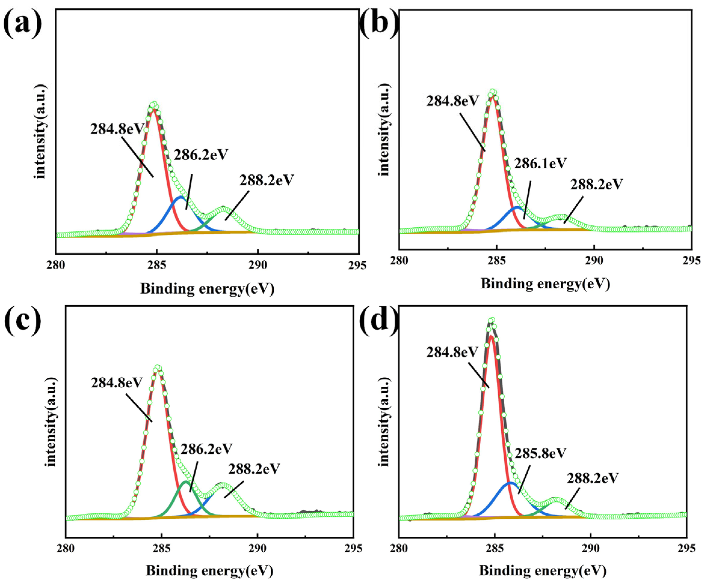
| Φ | SP2 | SP3 | C–O | ISP2/ISP3 |
|---|---|---|---|---|
| 0 | 284.8 | 286.2 | 288.2 | 4.034 |
| 0.15 | 284.8 | 286.1 | 288.2 | 4.72 |
| 0.4 | 284.8 | 286.2 | 288.2 | 4.58 |
| 0.75 | 284.8 | 285.8 | 288.2 | 3.21 |
Disclaimer/Publisher’s Note: The statements, opinions and data contained in all publications are solely those of the individual author(s) and contributor(s) and not of MDPI and/or the editor(s). MDPI and/or the editor(s) disclaim responsibility for any injury to people or property resulting from any ideas, methods, instructions or products referred to in the content. |
© 2024 by the authors. Licensee MDPI, Basel, Switzerland. This article is an open access article distributed under the terms and conditions of the Creative Commons Attribution (CC BY) license (https://creativecommons.org/licenses/by/4.0/).
Share and Cite
Zhang, J.; Min, B.-W.; Gu, H.; Wu, G.-Q.; Dai, G.-Q.; Sun, Z.-G. Grain Refinement and Mechanical Enhancement of Titanium Matrix Composites with Nickel-Coated Graphene Nanoflakes: Influence of Particle-Size Mismatch. Crystals 2024, 14, 516. https://doi.org/10.3390/cryst14060516
Zhang J, Min B-W, Gu H, Wu G-Q, Dai G-Q, Sun Z-G. Grain Refinement and Mechanical Enhancement of Titanium Matrix Composites with Nickel-Coated Graphene Nanoflakes: Influence of Particle-Size Mismatch. Crystals. 2024; 14(6):516. https://doi.org/10.3390/cryst14060516
Chicago/Turabian StyleZhang, Jie, Byung-Won Min, Hai Gu, Guo-Qing Wu, Guo-Qing Dai, and Zhong-Gang Sun. 2024. "Grain Refinement and Mechanical Enhancement of Titanium Matrix Composites with Nickel-Coated Graphene Nanoflakes: Influence of Particle-Size Mismatch" Crystals 14, no. 6: 516. https://doi.org/10.3390/cryst14060516