Article

A Comparative Study of Microstructural Characteristics and Mechanical Properties of High-Strength Low-Alloy Steel Fabricated by Wire-Fed Laser Versus Wire Arc Additive Manufacturing

1
Ansteel Beijing Research Institute Co., Ltd., Beijing 102209, China
2
Ningbo Branch of Chinese Academy of Ordnance Science, Ningbo 315103, China
3
Cold Rolled Strip Steel Mill of Angang Steel Co., Ltd., Anshan 114021, China
*
Authors to whom correspondence should be addressed.
Crystals 2024, 14(6), 528; https://doi.org/10.3390/cryst14060528
Submission received: 8 May 2024 / Revised: 24 May 2024 / Accepted: 27 May 2024 / Published: 31 May 2024
(This article belongs to the Section Crystalline Metals and Alloys)

Abstract

:
This study evaluates the feasibility of producing high-strength low-alloy (HSLA) steel using advanced wire-fed laser additive manufacturing (LAM-W) and wire arc additive manufacturing (WAAM) technologies. Optimized parameters were independently developed for each heat source, utilizing a self-designed HSLA steel wire as the feedstock. Microstructural features and mechanical properties of the fabricated steels were characterized and compared, taking into account differences in heat input and cooling rates. LAM-W samples exhibited a finer columnar grain microstructure, while both LAM-W- and WAAM-produced steels predominantly showed lower bainite and granular bainite microstructures. LAM-W demonstrated higher strength and hardness, lower ductility, and comparable low-temperature toughness compared to WAAM. Both processes demonstrated an excellent balance between strength and ductility, with absorbed energy exceeding 100 J at −40 °C. The study confirms the feasibility of producing high-strength and tough HSLA steel parts using LAM-W and WAAM technologies, and compares the advantages and disadvantages of each method. These findings assist in selecting the most suitable wire-fed AM process for HSLA steel fabrication at high deposition rates.

1. Introduction

Additive manufacturing (AM), commonly known as 3D printing, has seen significant advancements with its layer-by-layer deposition technique. This approach reduces production lead times, optimizes material usage, and enhances manufacturing adaptability compared to traditional methods [1,2]. Consequently, AM has gained widespread acceptance across diverse industries such as defense, aerospace, medical, and automotive sectors [3,4,5].
Wire-based additive manufacturing (AM), in contrast to powder-based methods, presents superior deposition rates, dimensional flexibility, and cost-efficiency in material deposition [6]. Employing arc heat sources, laser beams, or electron beams, this approach melts wire feedstock [7,8,9], operating at power levels of kilowatts or higher. Consequently, these techniques offer economic benefits, producing near-net-shaped components at rates ranging from kilograms to multi-kilograms per hour [10].
Wire-fed laser additive manufacturing (LAM-W), a technique within directed energy deposition, integrates high-power lasers with CNC machines and wire feeders [11,12]. These lasers induce a molten melt pool, facilitating the introduction of metal wire, resulting in a superior resolution owing to fine wire sizes and precise focusing. Nonetheless, its operational cost per unit of deposited metal is moderately elevated, impacted by factors such as laser hazards and capital equipment expenses. Wire arc additive manufacturing (WAAM), employing conventional wire-fed arc or plasma welding sources with modern robotic or CNC motion systems, provides a cost-effective alternative to LAM-W [13]. Despite being less precise, WAAM benefits from lower expenses associated with traditional arc welding power supplies and supports various heat sources like plasma arc, gas tungsten arc, or gas metal arc (GMA) processes [13]. Compared to LAM-W, WAAM has a higher heat input, higher processing efficiency, and lower cost, but the microstructure tends to be coarse and the surface quality is poor [7].
High-strength low-alloy (HSLA) steels are widely utilized in structural applications owing to their combination of strength, ductility, toughness, weldability, and cost-effectiveness [14]. Achieving the desired balance of strength and toughness involves a careful alloy composition design and the use of thermomechanical control processing (TMCP) [15,16]. Wire-based additive manufacturing offers a swift and economical means of producing intricate parts from HSLA steels, particularly in marine and offshore engineering applications such as a marine drilling platform rack.
Recent research has extensively explored the production of thin-wall components using WAAM HSLA steels [17,18,19]. Qian Fang et al. [20,21] investigated block parts of HSLA steel fabricated by WAAM, revealing that proper heat input can yield dense and sound parts with a balanced strength–ductility–toughness profile. Additionally, studies have examined the feasibility of the LAM-W process for various steel components, including 316L stainless steel, ER321 stainless steel, H13 steel, H11 steel, and ultra-high-strength martensitic steel [22,23,24,25,26]. However, few works on HSLA steel components fabricated by LAM-W have been reported. When fabricating large components for marine engineering, it is crucial to meet strict mechanical property requirements while also considering fabrication efficiency and surface quality. The microstructure, mechanical properties, and fabrication efficiency of HSLA steel parts fabricated using LAM-W or WAAM are primarily influenced by wire compositions and the specific processes involved, differing notably from conventional methods [17].
Therefore, this study evaluates the advantages and limitations of producing HSLA steel components for marine engineering using LAM-W and WAAM technologies. HSLA steel blocks, designed for high yield strength and low-temperature toughness, were fabricated via both methods. Comprehensive characterization included an analysis of build parameters and evaluation of microstructure, composition, tensile, and impact properties across different orientations relative to the AM build geometry. These findings provide insights into the feasibility of each wire-fed process for fabricating HSLA steel components, enhancing understanding of their suitability in marine engineering.

2. Materials and Methods
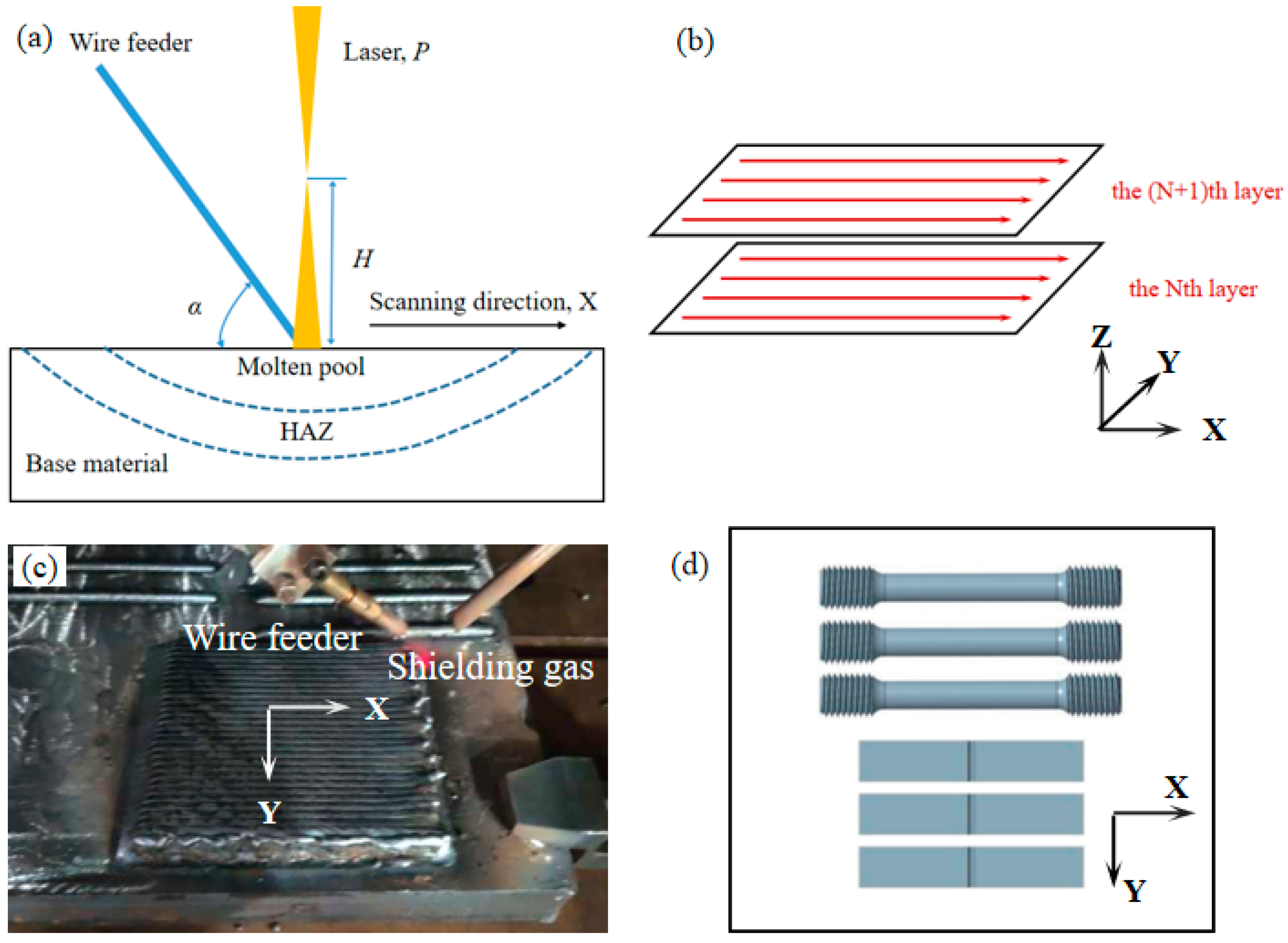
2.1. LAM-W

The LAM-W samples were fabricated using an IPG YLS 6000 laser (IPG Photonics Corporation, Oxford, MA, USA) equipped with an Intane W-306 wire feed head (Nanjing Intane Laser Technology Co., Ltd., Nanjing, China). The schematic diagram of LAM-W is depicted in Figure 1a, illustrating the side-fed wire onto the laser beam center, resulting in a melt pool. The setup positions the wire feeder, laser beam, and scanning direction on the same plane. LAM-W employed a 1.2 mm welding wire designed for 800 MPa class high-strength steel (composition shown in Table 1) to build a 115 × 95 × 20 mm brick on a 25 mm thick Q235 steel substrate using Ar shielding gas. The weld travel speed was set at 10 mm/s. The angle α between the wire and the horizontal plane was 30°, with a laser defocus amount H of 50 mm. Additional build and welding parameters are summarized in Table 2, considering a laser spot size of 2 mm diameter.
The brick was constructed with a deposition strategy maintaining the travel direction along the X-axis between passes in Figure 1b, with approximately a 40% overlap of 1.4 mm for 3 mm wide weld beads. At the end of each pass, the laser and wire feeding system halts, and returns to the starting point of the last pass. Then, it moves 1.4 mm along the Y-axis to serve as the starting position for the next pass. At the end of each layer, the laser returns to the initial starting position of the first pass and is offset 0.7 mm upward, serving as the starting point for the next layer. To prevent pad overheating, the sample was cooled between layers. The final brick comprised 30 layers, produced with a heat input of 320 J/mm. Figure 1c presents the produced deposit.

2.2. WAAM

WAAM was performed using an 8-axis robotic welder to fabricate shapes from the same wire as LAM-W. The robotic cell featured a Fronius CMT GMAW power supply (Fronius International GmbH, Wels, Upper Austria, Austria) and torch, utilized to fabricate a 200 × 200 × 20 mm solid brick on a 25 mm thick Q235 steel substrate. The schematic diagram of WAAM is shown in Figure 2a. The welding parameters, detailed in Table 2, included a constant wire feed speed of 9 m/min, an average welding voltage of approximately 30 V, and a current of 320 A. The power supply operated in pulsed CMT mode using an 80% Ar + 20% CO2 binary mix shielding gas at a flow rate of 25 L/min through the torch.
WAAM builds were executed at a weld travel speed of 5 mm/s, half the speed of LAM-W builds, resulting in a larger melt pool diameter of approximately 9 mm. A layer-by-layer approach was adopted to create the brick shape, filled using a serpentine pattern with a bead overlap of approximately 50%, as shown in Figure 2b. Additionally, wire brushing after each layer was performed to clean the surface and minimize the entrapment of surface oxides during the build. The completed solid brick is depicted in Figure 2c, prior to wire brushing to remove welding soot. The brick comprised 12 layers at a 2.2 mm offset height per layer, achieving a max. deposition rate of 3.8 kg/hr if the weld was run continuously. The build was conducted at a heat input of 1920 J/mm, approximately six times that of the LAM-W build, in order to achieve a high wire feed speed of 9 m/min, which is five times that of LAM-W.

2.3. Microstructure and Mechanical Properties Characterization

Metallurgical samples extracted from LAM-W and WAAM bricks underwent a series of processing steps for characterization. Initially, wire electrical discharge machining (WEDM), grinding, and polishing were performed on the samples, followed by etching with a 4% nital solution consisting of 4 mL HNO3 and 96 mL ethanol for optical microscope (OM) and scanning electron microscope (SEM) examinations. Furthermore, a disc-shaped sample with a thickness of 200 μm was randomly cut using WEDM from the deposit and ground to a thickness of 40–50 μm. Subsequently, this sample underwent twin-jet electropolishing in a solution containing 6% perchloric acid and 94% methanol for transmission electron microscope (TEM) observations and electron backscatter diffraction (EBSD) characterization with a step size of 1 μm. For macrostructure examination of the deposited passes, the metallurgical sample was immersed in a solution of saturated picric acid at 60 °C for 2 min.
Tensile samples and impact test samples were prepared by electrical discharge machining (EDM) extraction of blanks from the brick, followed by standard milling and turning to produce dog bone-like tensile test samples (M12Φ5) and impact test samples with V notches (55 × 10 × 10 mm). Tensile bars and impact test samples from the LAM-W brick were extracted from one principal orientation, X, parallel to the scanning direction, as shown in Figure 1d. Tensile bars and impact test samples from the WAAM brick were extracted from both X and Y directions in Figure 2d. Tensile testing of the bars was conducted using servo-hydraulic machines at room temperature and a strain rate of 2 × 10⁻³/s. The results, including yield strength, ultimate tensile strength, and elongation to failure, were recorded. Instrumented Charpy impact tests were performed three times per condition to obtain average values at −40 °C. Microhardness indentation was carried out on metallurgical samples using a 500g load (dwell time, 10 s), with a step size of 0.25 mm for LAM-W and 0.5 mm for WAAM.

3. Results and Discussion

3.1. Microstructural Characterizations

The microstructures of the LAM-W samples, as depicted in Figure 3, reveal crescent-shaped overlapping beads. The deposit unit, defined in reference [27], measures approximately 3 mm wide and 1 mm high and can be segmented into two distinct regions based on microstructural morphology: the fine column grain region and the coarse column grain region in Figure 3b.
The fine column grain region, predominant within the deposit unit, forms at the bottom under rapid cooling rates. Columnar grain structure perpendicular to the crescent edge in additive manufacturing arises from rapid solidification and significant vertical temperature gradients, prompting metal material to develop columnar grains along the solidification direction. This region primarily comprises lower bainite (LB) and granular bainite (GB) (Figure 3c), with a column width of approximately 5 μm.
The coarse columnar grain region is positioned in the upper part of the deposit unit, just below the fusion line of the subsequent deposit unit. This region comprises LB and GB, as depicted in Figure 3d. The width of the coarse column is approximately 10 μm, twice the size of the fine columnar grains. Additionally, the carbide size within the bainitic structures in the coarse columnar grain region is larger. The coarser columnar microstructure forms due to the lower temperature gradient in the middle and top sections of the weld pool, while a fine columnar microstructure develops at the bottom, where the temperature gradient is higher [28]. Slower cooling rates in the middle and top sections facilitate carbon diffusion, leading to the formation of larger carbide particles and carbide coarsening within the bainitic structures.
The morphology of the bainite is illustrated in Figure 3e,f. The original austenite grains are segmented into several lath bundles composed of parallel plates. Within the same bainitic lath bundle, a significant number of laths exhibit consistent alignment, being parallel to each other, and are separated by low-angle grain boundaries. The bainitic structures exhibit a higher dislocation density, contributing to increased strength.
Figure 4a displays a cross-section capturing multiple passes in the WAAM process. The microstructure in WAAM exhibits a distinctive crescent shape and consists of repetitive deposit units. Each deposit unit measures approximately 9 mm in width and 4 mm in depth, significantly larger than the LAM-W specimens. In Figure 4b, the depicted segment focuses on the part of the fusion line within the deposit unit.
Similar to the LAM-W samples, the deposit unit in WAAM can be subdivided into two regions. These regions are identified as the fine column grain region (denoted by black symbol ‘c’) and the coarse column grain region, as shown in Figure 4b.
The fine column grain region, predominantly occupying the bottom of the deposit unit above the fusion line, is characterized by a rapid cooling rate during formation. It mainly consists of LB and GB, as shown in Figure 4c. The width of the fine column is approximately 15 μm.
In contrast, the upper portion of the deposit unit below the fusion line constitutes the coarse column grain region, characterized by a width of 50 μm, more than three times larger than the fine column grain region. Figure 4d reveals a decreased presence of LB and GB in this coarse column grain region compared to the fine column grain region. Similar to LAM-W, the microstructure in the lower section of the additive manufacturing fusion line undergoes columnar grain coarsening due to the lower temperature gradient in the middle and top sections of the weld pool, resulting in a reduced occurrence of bainite, predominantly in the form of GB.
Compared to LAM-W, WAAM exhibits a reduction in the volume percentage of bainitic carbides and a coarser bainitic microstructure. The disparity in microstructural characteristics between WAAM and LAM-W can be attributed to a higher heat input in WAAM. Fang Q et al. [21] demonstrated that the microstructure of WAAM samples fabricated using similar HSLA wire undergoes a coarsening of GB and an increase in its proportion with increasing heat input. EBSD and TEM analyses revealed that WAAM samples prepared with a heat input of 1890 J/mm, similar to that used in this study, exhibit coarser effective grain sizes and ferrite laths, along with reduced dislocation density, compared to those of LAM-W, as shown in Figure 3e,f. The intense heat generated by the electric arc in WAAM results in slower cooling rates during material solidification, influencing the kinetics of phase transformations. This extended solidification time leads to a decreased volume percentage of bainitic carbides in WAAM compared to LAM-W. Additionally, the slower cooling rates contribute to the coarsening of carbides within the bainitic microstructure in WAAM, resulting in larger carbide particles. These distinctive microstructural features in WAAM are a consequence of the prolonged exposure to elevated temperatures during the additive manufacturing process.

3.2. Mechanical Properties

3.2.1. Hardness

Figure 5 reveals the nonuniform distribution of hardness within the passes (separated by red lines) in the as-deposited part of both LAM-W and WAAM, contributed by different thermal histories. The variation in the microhardness values within the marked passes of LAM-W is in the range of 263 to 359 HV, with an average value of approximately 314 HV. The hardness cloud map could be divided into two parts: (a) 320~359 HV, which could be defined as the hardened zones, correlated to the fine column grain zone above the fusion lines; and (b) 263~320 HV, which could be defined as the softened zones. The coarse column grain zone is near the fusion line with a coarse column grain region. The microhardness within the deposit varies periodically from pass to pass, which corresponds well with the periodic repetition of microstructure in the deposition units, as shown in Figure 3a.
Figure 5b illustrates the distribution of hardness within the marked passes (indicated by red lines) in the WAAM sample. The microhardness values within these marked passes range from 222 to 287 HV, with an average value of approximately 253 HV. There is a noticeable softened zone below the fusion line at the bottom of the deposition unit, with hardness lower than 250 HV. No distinct hardened zones are observed. The periodicity of hardness distribution may not be clearly evident due to the small size of the selected WAAM testing area. The larger melt pool in WAAM samples, stemming from the additive manufacturing process, results in a more intricate thermal environment during solidification.
In comparison with the LAM-W sample, the hardness distribution in the illustrated WAAM sample shows lower hardness values, a narrower range and a more uniform distribution. The decrease in the volume percentage of bainitic carbides, along with a coarser bainitic microstructure and reduced dislocation density, contribute to the lower hardness values observed in WAAM.

3.2.2. Tensile Properties

For the WAAM brick, tensile bars were extracted along both X and Y directions. Table 3 data reveal that the average ultimate strength is higher in the X direction, increasing from 805 MPa (X) to 798.5 MPa (Y). Conversely, the average yield strength increased from 632.5 MPa (X) to 676 MPa (Y). The elongation values are similar in both directions, varying from 22% (X) to 21.5% (Y), respectively.
In contrast, for the LAM-W brick, the tensile specimens were obtained from the X direction. The average ultimate strength and average yield strength are 940 MPa (LAM-W) and 902 MPa (LAM-W), respectively, higher than 805 MPa (WAAM) and 632.5 MPa (WAAM). The elongation values decreased from 22% (WAAM) to 12.5% (LAM-W). This could be explained by the faster cooling rate and lower heat input of LAM-W.
Based on the SEM images of the fracture surfaces of LAM-W and WAAM tensile specimens in Figure 6, the overall fracture morphology exhibits the characteristic microvoid clustering typical of ductile metals. The fracture dimples in LAM-W are smaller and more uniformly distributed, while those on the WAAM fracture surface are larger and exhibit uneven sizes. WAAM demonstrates better plasticity compared to LAM-W. In conclusion, compared to WAAM, LAM-W demonstrates higher strength and lower plasticity. A trade-off between strength and ductility is evident in the LAM-W and WAAM components. The lower yield strength and higher plasticity in WAAM can be attributed to the reduction in the volume percentage of bainitic carbides, along with the presence of coarser effective grain sizes and ferrite laths, as well as a decreased dislocation density in the microstructure. The WAAM brick does not exhibit significant anisotropy in terms of strength and plasticity. Notably, the WAAM brick displays minimal anisotropy concerning both strength and plasticity. Further exploration into the mechanical property anisotropy of LAM-W and WAAM will be pursued in our subsequent research.

3.2.3. Low-Temperature Impact Toughness

The low-temperature impact properties are detailed in Table 3, with specimens taken for WAAM along both the X and Y directions. In the X direction, the average absorbed energy at −40 °C is 136 J, surpassing that of the Y direction at 131.7 J.
In comparison, for LAM-W, the average absorbed energy at −40 °C along the X direction is 125 J, which is less than that of WAAM at 136 J. The low-temperature impact properties of WAAM do not exhibit significant anisotropy in either direction. Both LAM-W and WAAM exhibit high performance in low-temperature toughness. The interlaced distribution of LB and a certain range of dislocation density is conducive to improving crack propagation resistance and thereby enhancing low-temperature toughness.
Figure 7 illustrates the impact sample fractography of WAAM along the X direction. The crack undergoes a prolonged ductile region, denoted by the black symbol ‘b’, before transitioning to the quasi-cleavage region, denoted by the black symbol ‘c’. The ductile region is uniformly distributed with deep dimples (Figure 7b), and the bottoms of these ductile dimples appear clean without the presence of inclusions. The quasi-cleavage region (Figure 7c) exhibits a mixed morphology characterized by a combination of ductile and brittle features, with a predominance of brittle fracture morphology. LAM-W samples show a similar impact fracture morphology. Overall, both WAAM and LAM-W demonstrate commendable strength and toughness, and the choice between the two manufacturing methods should be determined based on specific requirements.

3.3. Qualitative Comparison of LAM-W and WAAM

These two manufacturing processes exhibit unique strengths and weaknesses, covering aspects such as cost, microstructural properties, deposition rate, surface finish, and mechanical performance. These factors are crucial when selecting a specific manufacturing technique and are heavily influenced by the specific requirements of the final product. Detailed evaluations of processing parameters and outcomes for each method are meticulously presented in Table 2 and Table 3, providing valuable insights for informed decision-making.
The analysis reveals that the heat input of WAAM exceeds that of LAM-W by approximately sixfold. Comparisons between the processes are intricately linked to heat input, with WAAM showcasing superior deposition efficiency. WAAM exhibits a deposition rate of over five times that of LAM-W, reaching approximately 4 kg/h. LAM-W yields smaller weld bead sizes and layer heights, resulting in superior surface quality due to finer melt pool dimensions and precise control over melt pool behavior.
Regarding the mechanical properties of HSLA materials, both processes achieve a favorable balance of strength, plasticity, and toughness. The LAM-W process delivers higher strength and lower plasticity, whereas the WAAM process yields lower strength and higher plasticity. This discrepancy can be attributed to the concentrated energy of LAM-W, evidenced by its higher energy/amount deposited, nearly twice that of WAAM. Consequently, LAM-W undergoes greater temperature gradients and faster cooling rates (above 500 k/s), promoting the development of a finer microstructure compared to WAAM (below 20 k/s) [19,29]. Both techniques demonstrate outstanding low-temperature toughness. While WAAM samples exhibit no significant mechanical performance anisotropy, further investigation is required to assess the anisotropy of LAM-W performance.
When the cost per kilogram of deposited material is paramount, WAAM emerges as a favorable option due to its higher deposition rate, lower operational and capital equipment costs, and decreased heat input. Conversely, when optimizing strength becomes a critical design criterion, combined with exacting demands for shape and surface quality, LAM-W stands out as a compelling choice.

4. Conclusions

In summary, the microstructure and mechanical properties of HSLA parts manufactured using two wire-based additive manufacturing technologies, LAM-W and WAAM, were evaluated, leading to the following conclusions:
  • When comparing the two wire-based additive manufacturing processes of LAM-W and WAAM using optimal process parameters, significant differences become evident. LAM-W operates at high weld speed, producing a smaller weld pool and lower heat input, whereas WAAM operates at a slower weld speed with a larger weld pool, resulting in heat input six times that of the laser process. However, considering the metal wire feed rate, the energy deposited per kilogram of metal varies only 1.5 times between these two processes, with WAAM proving more efficient.
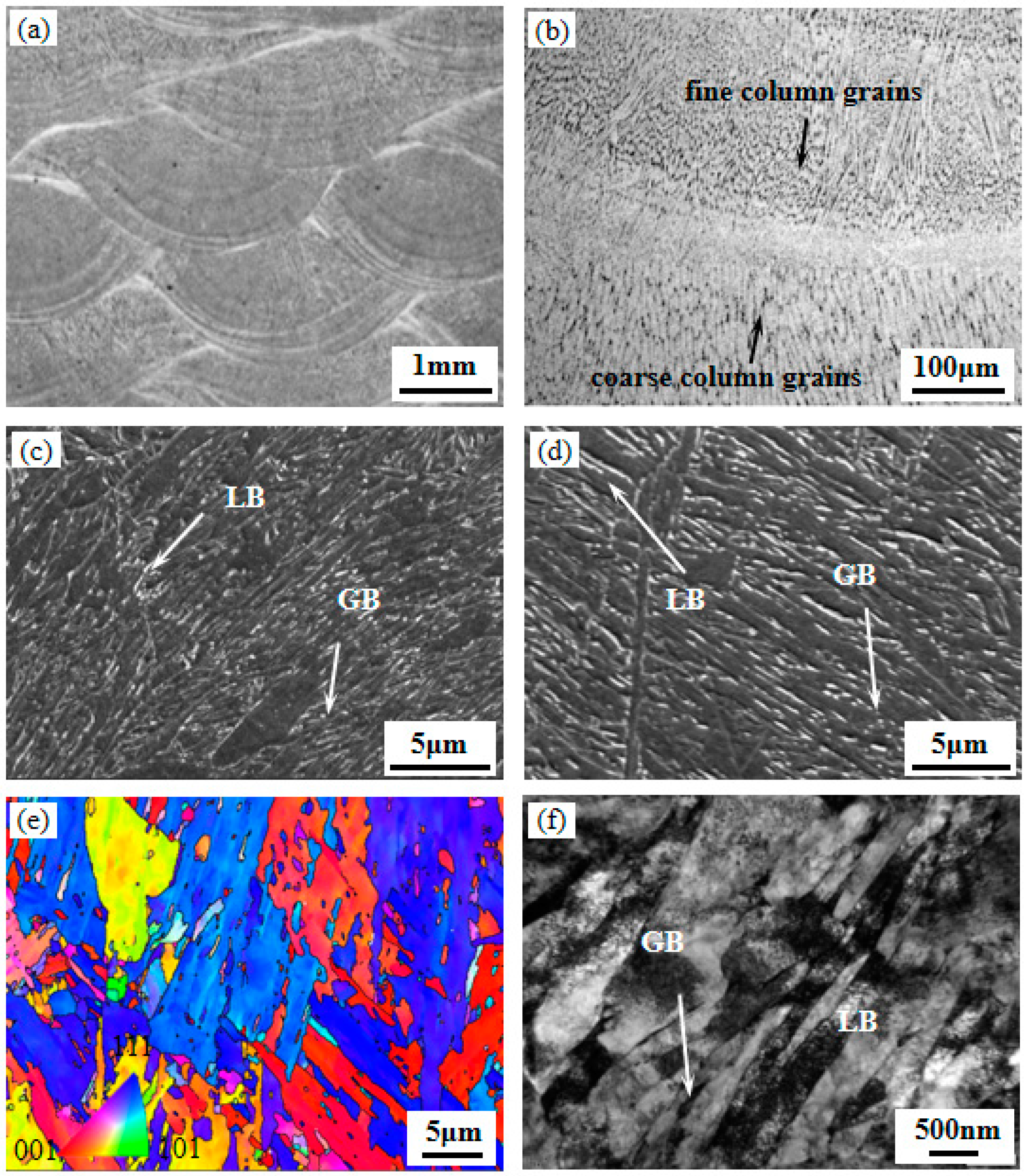
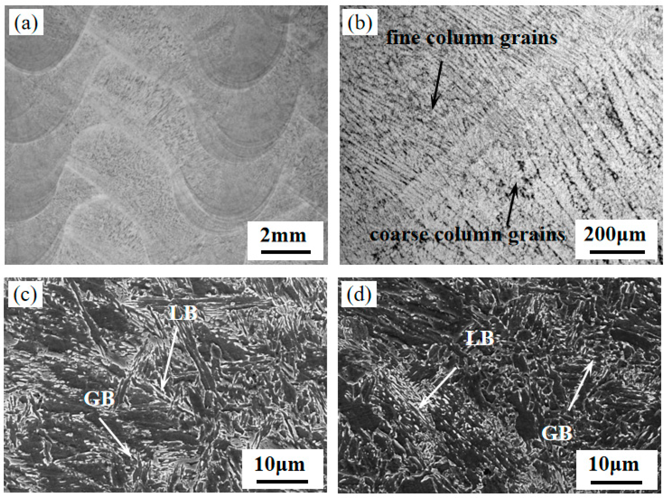
  • The heat input differential between LAM-W and WAAM leads to variances in microstructural characteristics. LAM-W demonstrates a faster cooling rate during solidification compared to WAAM. Both LAM-W and WAAM microstructures comprise a mixture of lower bainite and granular bainite. Compared to LAM-W, WAAM exhibits a coarser bainitic microstructure and reduced volume percentages of bainitic carbides. The column grain size in WAAM is approximately three to five times that of LAM-W.
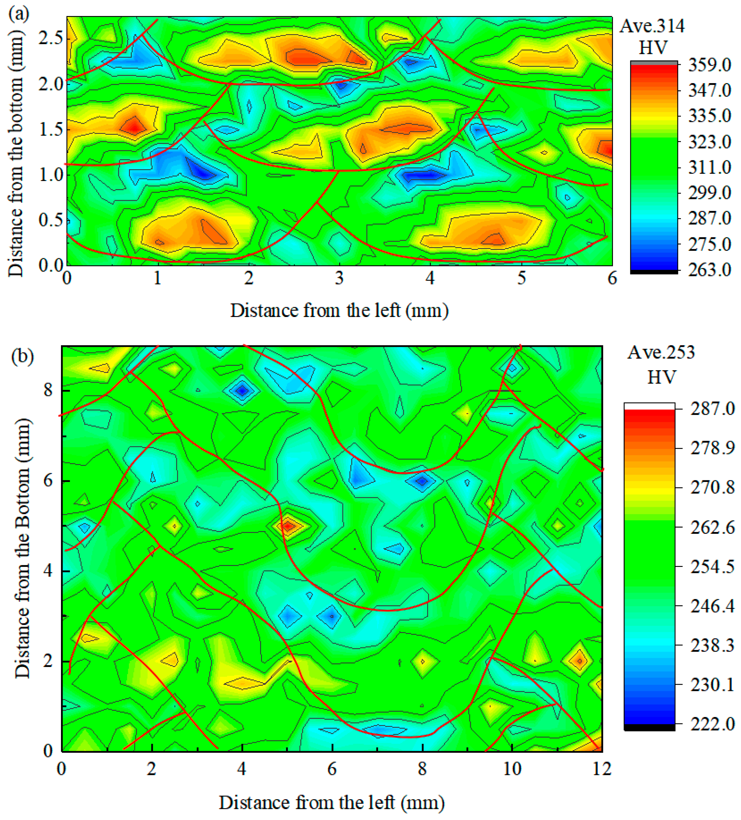
  • While both processes demonstrate favorable mechanical properties, LAM-W exhibits superior strength and hardness compared to WAAM, while WAAM shows higher ductility. These distinctions arise from the effects of heat input on microstructure. Despite variations in process parameters, both processes exhibit comparable low-temperature toughness. The microhardness distribution across the deposited part is non-uniform and varies periodically from pass to pass, perpendicular to the scanning direction, with LAM-W displaying a broader hardness range than WAAM.
  • A comparative analysis of LAM-W and WAAM reveals their respective advantages, with the choice depending on the specific application. Based on the parameters outlined here, LAM-W demonstrates superior weld pool control and higher strength, giving it an advantage when prioritizing surface finish and strength. On the other hand, WAAM offers lower costs, higher production rates, and good overall mechanical performance, making it advantageous for larger parts.

Author Contributions

Conceptualization, D.Z. and Q.F.; methodology, B.L. and Z.H.; writing—original draft preparation, D.Z. and Y.J.; writing—review and editing, D.Z. and Q.F.; supervision, Y.W. and Z.H.; funding acquisition, B.L. and S.S. All authors have read and agreed to the published version of the manuscript.

Funding

This research was funded by the National Key Research and Development Program (No. 2021YFB3702003).

Data Availability Statement

The original contributions presented in the study are included in the article. Further inquiries can be directed to the corresponding author/s.

Conflicts of Interest

Author Dayue Zhang, Binzhou Li, Yijia Wang, Shanshan Si, and Yuanbo Jiang were employed by the company Ansteel Beijing Research Institute Co., Ltd. Zhiping Hu was employed by Cold Rolled Strip Steel Mill of Angang Steel Co., Ltd. The remaining authors declare that the research was conducted in the absence of any commercial or financial relationships that could be construed as a potential conflict of interest.

References

  1. Liu, G.; Zhang, X.; Chen, X.; He, Y.; Cheng, L.; Huo, M.; Yin, J.; Hao, F.; Chen, S.; Wang, P.; et al. Additive manufacturing of structural materials. Mater. Sci. Eng. R Rep. 2021, 145, 100596. [Google Scholar] [CrossRef]
  2. Truby, R.L.; Lewis, J.A. Printing soft matter in three dimensions. Nature 2016, 540, 371–378. [Google Scholar] [CrossRef]
  3. Vafadar, A.; Guzzomi, F.; Rassau, A.; Hayward, K. Advances in Metal Additive Manufacturing: A Review of Common Processes, Industrial Applications, and Current Challenges. Appl. Sci. 2021, 11, 1213. [Google Scholar] [CrossRef]
  4. Vishnukumar, M.; Pramod, R.; Rajesh Kannan, A. Wire arc additive manufacturing for repairing aluminium structures in marine applications. Mater. Lett. 2021, 299, 130112. [Google Scholar] [CrossRef]
  5. Salmi, M. Additive Manufacturing Processes in Medical Applications. Materials 2021, 14, 191. [Google Scholar] [CrossRef]
  6. Sames, W.J.; List, F.A.; Pannala, S.; Dehoff, R.R.; Babu, S.S. The metallurgy and processing science of metal additive manufacturing. Int. Mater. Rev. 2016, 61, 315–360. [Google Scholar] [CrossRef]
  7. Elmer, J.W.; Vaja, J.; Carpenter, J.S.; Coughlin, D.R.; Dvornak, M.J.; Hochanadel, P.; Gurung, P.; Johnson, A.; Gibbs, G.J.W.J. Wire-based additive manufacturing of stainless steel components. Weld. J. 2020, 99, 1–36. [Google Scholar] [CrossRef]
  8. Elmer, J.W.; Vaja, J.; Carpenter, J.S.; Coughlin, D.R.; Dvornak, M.J.; Hochanadel, P.; Gurung, P.; Johnson, A.; Gibbs, G. Gas metal arc welding based additive manufacturing—A review. CIRP J. Manuf. Sci. Technol. 2021, 33, 398–442. [Google Scholar]
  9. DebRoy, T.; Wei, H.L.; Zuback, J.S.; Mukherjee, T.; Elmer, J.W.; Milewski, J.O.; Beese, A.M.; Wilson-Heid, A.; De, A.; Zhang, W. Additive manufacturing of metallic components—Process, structure and properties. Prog. Mater. Sci. 2018, 92, 112–224. [Google Scholar] [CrossRef]
  10. DebRoy, T.; Mukherjee, T.; Milewski, J.O.; Elmer, J.W.; Ribic, B.; Blecher, J.J.; Zhang, W. Scientific, technological and economic issues in metal printing and their solutions. Nat. Mater. 2019, 18, 1026–1032. [Google Scholar] [CrossRef]
  11. Demir, A.G. Micro laser metal wire deposition for additive manufacturing of thin-walled structures. Opt. Lasers Eng. 2018, 100, 9–17. [Google Scholar] [CrossRef]
  12. Martina, F.; Mehnen, J.; Williams, S.W.; Colegrove, P.; Wang, F. Investigation of the benefits of plasma deposition for the additive layer manufacture of Ti–6Al–4V. J. Mater. Process. Technol. 2012, 212, 1377–1386. [Google Scholar] [CrossRef]
  13. Ding, D.; Pan, Z.; Cuiuri, D.; Li, H. Wire-feed additive manufacturing of metal components: Technologies, developments and future interests. Int. J. Adv. Manuf. Technol. 2015, 81, 465–481. [Google Scholar] [CrossRef]
  14. Bajaj, P.; Hariharan, A.; Kini, A.; Kürnsteiner, P.; Raabe, D.; Jägle, E.A. Steels in additive manufacturing: A review of their microstructure and properties. Mater. Sci. Eng. A 2020, 772, 138633. [Google Scholar] [CrossRef]
  15. Li, X.; Ma, X.; Subramanian, S.V.; Shang, C.; Misra, R.D.K. Influence of prior austenite grain size on martensite–austenite constituent and toughness in the heat affected zone of 700 MPa high strength linepipe steel. Mater. Sci. Eng. A 2014, 616, 141–147. [Google Scholar] [CrossRef]
  16. Zhang, D.; Strangwood, M. Interdendritic microsegregation development of high-strength low-alloy steels during continuous casting process. Mater. Sci. Technol. 2019, 35, 1337–1346. [Google Scholar] [CrossRef]
  17. Nemani, A.V.; Ghaffari, M.; Nasiri, A.J.A.M. Comparison of microstructural characteristics and mechanical properties of shipbuilding steel plates fabricated by conventional rolling versus wire arc additive manufacturing. Addit. Manuf. 2020, 32, 101086. [Google Scholar]
  18. Sun, L.; Jiang, F.; Huang, R.; Yuan, D.; Guo, C.; Wang, J. Anisotropic mechanical properties and deformation behavior of low-carbon high-strength steel component fabricated by wire and arc additive manufacturing. Mater. Sci. Eng. A 2020, 787, 139514. [Google Scholar] [CrossRef]
  19. Rodrigues, T.A.; Duarte, V.; Avila, J.A.; Santos, T.G.; Miranda, R.M.; Oliveira, J.P. Wire and arc additive manufacturing of HSLA steel: Effect of thermal cycles on microstructure and mechanical properties. Addit. Manuf. 2019, 27, 440–450. [Google Scholar] [CrossRef]
  20. Fang, Q.; Zhao, L.; Liu, B.; Chen, C.; Peng, Y.; Tian, Z.; Yin, F. Microstructure and Mechanical Properties of 800-MPa-Class High-Strength Low-Alloy Steel Part Fabricated by Wire Arc Additive Manufacturing. J. Mater. Eng. Perform. 2022, 31, 7461–7471. [Google Scholar] [CrossRef]
  21. Fang, Q.; Zhao, L.; Chen, C.; Zhu, Y.; Peng, Y.; Yin, F. Effect of heat input on microstructural and mechanical properties of high strength low alloy steel block parts fabricated by wire arc additive manufacturing. Mater. Today Commun. 2023, 34, 105146. [Google Scholar] [CrossRef]
  22. Shaikh, M.O.; Chen, C.-C.; Chiang, H.-C.; Chen, J.-R.; Chou, Y.-C.; Kuo, T.-Y.; Ameyama, K.; Chuang, C.-H. Additive manufacturing using fine wire-based laser metal deposition. Rapid Prototyp. J. 2020, 26, 473–483. [Google Scholar] [CrossRef]
  23. Yuan, D.; Sun, X.; Sun, L.; Zhang, Z.; Guo, C.; Wang, J.; Jiang, F. Improvement of the grain structure and mechanical properties of austenitic stainless steel fabricated by laser and wire additive manufacturing assisted with ultrasonic vibration. Mater. Sci. Eng. A 2021, 813, 141177. [Google Scholar] [CrossRef]
  24. Nie, Z.; Wang, G.; McGuffin-Cawley, J.D.; Narayanan, B.; Zhang, S.; Schwam, D.; Kottman, M.; Rong, Y.K. Experimental study and modeling of H13 steel deposition using laser hot-wire additive manufacturing. J. Mater. Process. Technol. 2016, 235, 171–186. [Google Scholar] [CrossRef]
  25. Oliari, S.H.; D’Oliveira, A.S.C.M.; Schulz, M. Additive manufacturing of H11 with wire-based laser metal deposition. Soldag. Inspeção 2017, 22, 466–479. [Google Scholar] [CrossRef]
  26. Seede, R.; Shoukr, D.; Zhang, B.; Whitt, A.; Gibbons, S.; Flater, P.; Elwany, A.; Arroyave, R.; Karaman, I. An ultra-high strength martensitic steel fabricated using selective laser melting additive manufacturing: Densification, microstructure, and mechanical properties. Acta Mater. 2020, 186, 199–214. [Google Scholar] [CrossRef]
  27. Fang, Q.; Zhao, L.; Chen, C.-X.; Cao, Y.; Song, L.; Peng, Y.; Yin, F.-X. 800 MPa Class HSLA Steel Block Part Fabricated by WAAM for Building Applications: Tensile Properties at Ambient and Elevated (600 °C) Temperature. Adv. Mater. Sci. Eng. 2022, 2022, 3014060. [Google Scholar] [CrossRef]
  28. Cong, B.; Qi, Z.; Qi, B.; Sun, H.; Zhao, G.; Ding, J. A comparative study of additively manufactured thin wall and block structure with Al-6. 3% Cu alloy using cold metal transfer process. Appl. Sci. 2017, 7, 275. [Google Scholar]
  29. Bernauer, C.; Sigl, M.E.; Grabmann, S.; Merk, T.; Zapata, A.; Zaeh, M.F. Effects of the thermal history on the microstructural and the mechanical properties of stainless steel 316 L parts produced by wire-based laser metal deposition. Mater. Sci. Eng. A 2024, 889, 145862. [Google Scholar] [CrossRef]
Figure 1. Schematic diagram (a), deposition strategy (b), the deposited brick (c) and schematic illustration of tensile tests and impact test sampling locations (d) for the LAM-W process.
Crystals 14 00528 g001
Figure 2. Schematic diagram (a), deposition strategy (b), side view of the completed solid brick (c) and schematic illustration of tensile tests and impact test sampling locations (d) for the WAAM process.
Crystals 14 00528 g002
Figure 3. (a) Low-magnification and (b) high-magnification optical micrographs of the LAM-W-fabricated sample depicting two distinguishable regions: the fine column grain region and the coarse column grain region; (c,d) high-magnification SEM micrographs of the fine column grain region and the coarse column grain region; (e) EBSD and (f) TEM images of bainitic microstructure.
Crystals 14 00528 g003
Figure 4. (a) Low-magnification and (b) high-magnification optical micrographs of the WAAM-fabricated sample depicting two distinguishable regions: the fine column grain region and the coarse column grain region; (c,d) high-magnification SEM micrographs of the fine column grain region and the coarse column grain regions.
Crystals 14 00528 g004
Figure 5. Hardness distribution across multiple passes in different sample cross-sections: (a) LAM-W sample and (b) WAAM sample, with the fusion lines indicated by the red lines. Note that the magnification is two times higher in a than b.
Crystals 14 00528 g005
Figure 6. SEM fracture morphology of tensile specimens (a) LAM-W and (b) WAAM along the X direction.
Crystals 14 00528 g006
Figure 7. Macroscopic (a) and microscopic (b,c) fracture morphology of impact test samples of WAAM along the X direction. (b,c) Enlarged images of regions marked as black symbols b and c in (a).
Crystals 14 00528 g007
Table 1. Compositions of the weld wire in wt% for LAM-W and WAAM processes.
ElementsNi + Cr + MoSiMnCPSOFe
Wire3.740.441.770.0670.00580.00330.0061Bal.
Table 2. Summary of two wire-based AM build parameters.
SpecimensHeat Source Powe r (W)Weld Speed (mm/s)Heat Input (J/mm)Wire Feed Speed (m/min)Max. Deposition Rate (kg/hr)Energy/Amount Deposited (J/gm)
LAM-W3200103201.80.812,000
WAAM9600 (320 A × 30 V)5192093.87200
Table 3. A summary of mechanical properties of LAM-W and WAAM samples along the different directions.
SampleYield Stress (MPa)UTS (MPa)Elongation to Failure (%)Impact Energy, −40 °C (J)
LAM-W (X)902 ± 6.6940 ± 7.512.5 ± 3.2126 ± 10.1
WAAM (X)632.5 ± 9.2805 ± 8.522 ± 1.4136 ± 8.9
WAAM (Y)676 ± 7.1798.5 ± 6.421.5 ± 2.1131.7 ± 12.1
Disclaimer/Publisher’s Note: The statements, opinions and data contained in all publications are solely those of the individual author(s) and contributor(s) and not of MDPI and/or the editor(s). MDPI and/or the editor(s) disclaim responsibility for any injury to people or property resulting from any ideas, methods, instructions or products referred to in the content.

