Article

The Temperature-Dependent Thermal Conductivity of C- and O-Doped Si3N4: First-Principles Calculations

1
Shandong Institute of Nonmetallic Materials, Jinan 250031, China
2
State Key Laboratory of Advanced Technology for Materials Synthesis and Processing, Wuhan University of Technology, Wuhan 430070, China
*
Authors to whom correspondence should be addressed.
Crystals 2024, 14(6), 549; https://doi.org/10.3390/cryst14060549
Submission received: 9 May 2024 / Revised: 8 June 2024 / Accepted: 9 June 2024 / Published: 13 June 2024
(This article belongs to the Section Materials for Energy Applications)

Abstract

:
Silicon nitride (Si3N4) possesses excellent mechanical properties and high thermal conductivity, which is an important feature in many applications. However, achieving the theoretically high thermal conductivity of Si3N4 in practice is challenging. In this study, we adopted a first-principles calculation method to assess the effects of doping β-Si3N4 and γ-Si3N4 with carbon and oxygen atoms. Applying geometric structure optimization combined with calculation of the electronic phonon properties generated a stable doped structure. The results revealed that carbon and oxygen doping have little effect on the Si3N4 unit cell size, but that oxygen doping increases the unit cell volume. Energy band structure and state density calculation results showed that carbon doping reduces the nitride band gap width, whereas oxygen doping results in an n-type Si3N4 semiconductor. The findings from this study are significant in establishing a basis for targeted increase of the thermal conductivity of Si3N4.

1. Introduction

Silicon nitride (Si3N4) exhibits excellent mechanical properties, high chemical stability, and superior wear and thermal shock resistance [1,2]. Furthermore, Si3N4 also exhibits high thermal conductivity. Its intrinsic thermal conductivity has been reported to be about 200–320 W/m·K at room temperature [3]. Currently, silicon nitride ceramics are mainly employed as insulating substrates for high-power electronic devices [4]. However, the high thermal conductivity of as-received Si3N4 is not easy to attain in reality. Sintered polycrystalline Si3N4 ceramics have much lower thermal conductivity than the intrinsic thermal conductivity of the compound. It is believed that residual pores, as well as intergranular secondary phase and lattice imperfections including impurity atoms, vacancies, dislocations, and stacking faults, could affect thermal conductivity [5,6,7].
Because of this, many studies have attempted to improve the thermal conductivity of Si3N4. Horng-Hwa Lu and Jow-Lay Huang [8] systematically explored the effects of raw powders, especially phase composition, on the final microstructure of sintered Si3N4. And then, Hiroshi Yokota and Masahiro Ibukiyama studied the effects of the raw particle size distribution of Si3N4 powder using Yb2O3 and ZrO2 as sintering additives [9]. They found that it is possible for Si3N4 ceramics to achieve high thermal conductivity and high strength simultaneously by optimizing the particle size. In another study, Y Zhou et al. proposed using sintered reaction-bonded silicon nitride (SRBSN). The new technological method not only had a lower cost but also a higher possibility of attaining high thermal conductivity [10].
Notably, most of these works focused on microstructural features, including the relative density, the grain boundary, and the intergranular secondary phase, but few works have addressed impurity atoms. Oxygen and carbon, which can enter the Si3N4 lattice to form a solid solution phase during fabrication, are widely recognized as being the most detrimental impurities to the thermal conductivity of Si3N4 ceramics [11,12]. It is said that the impurity atoms can form silicon vacancies that scatter phonons [13,14]. Some studies have demonstrated that the elimination of lattice oxygen is crucial for improving the thermal conductivity of Si3N4 ceramics by adding oxide additives [15].
However, with regard to commercial applications, various kinds of silicon nitride powders with different high oxygen contents should be considered as the starting material. It is costly to optimize additivities for different raw powders or choose the proper raw powder. Therefore, a deep understanding of the effect of impurity atoms on thermal conductivity will be helpful for real-world industrial application. Huimin Xiang et al. [16] showed that first-principles theory and its related numerical methods are effective tools for predicting the thermal conductivity of Si3N4 with different crystal lattices. Based on these results, the effects of impurities on the thermal conductivity of different Si3N4 lattices were studied using a similar method.

2. Calculation Method

2.1. Theoretical Model

The theoretical analysis considered two crystalline forms of Si3N4, i.e., β-Si3N4 and γ-Si3N4. The space group for hexagonal β-Si3N4 is P63/m, as shown in Figure 1. This structure is composed of slightly twisted corner-congruent silicon–nitrogen tetrahedra, forming a hexagonal ring layer. Each β-Si3N4 unit cell contains 14 atoms, and the unit cell parameters are a = b = 7.607 Å, c = 2.911 Å, α = β = 90°, and γ = 120°. The calculations performed in this study used a 2 × 2 × 2 supercell model with a total of 112 atoms, obtained by extending the β-Si3N4 primitive cell by one unit along the basis vector x, y, and z directions. Carbon doping replaces Si atoms in the supercell, whereas oxygen doping replaces N atoms.

2.2. Calculations

Two density functional theory (DFT)-based codes, the Vienna Ab initio Simulation Package (VASP) [3,4] and the orthogonalized linear combination of atomic orbitals (OLCAO) code [5,6], were used in this study. The optimized VASP structures were used as inputs to calculate the electronic structure and interatomic bonding properties using an in-house OLCAO package. The OLCAO package uses the local density approximation (LDA) as the exchange and correlation potential. Atomic orbitals expanded in Gaussian-type orbitals (GTOs) are used for the basis set expansion of the wave functions. The use of localized atomic orbitals in the basis expansion contrasts with the plane-wave expansion used in VASP.
In terms of geometric structure optimization, a generalized gradient approximation (GGA) function was used to approximate the exchange correlation potential [7]. Taking into account the subsequent phonon calculation, the two Si3N4 crystal models, β-Si3N4 and γ-Si3N4, were continuously optimized until the energy difference and force difference were less than 1 × 10⁻⁸ eV/atom and 0.001 eV/Å, respectively, and the cutoff energy was set at 500 eV. In addition, 2 × 2 × 4 k mesh point sampling was used for both the β-Si3N4 and γ-Si3N4 systems. The atomic pseudo-potentials described using the projection enhanced plane wave (PAW) method [8] are Si-3s2 p2, N-2s2 p3, O-2s2 2p4, and C-2s2 2p2. The bond order (BO) values are given by Equation (1), also called the overlap population ραβ between any pair of atoms (α, β).
Q α = i m , o c c j , β C i α m C j β m S i α , j β
Moreover, Phonopy software (v 2.24.1), based on quasi-harmonic approximation, was used to calculate the second-order force constant and phonon spectrum, applying the density functional perturbation method [9]. As phonon thermal conduction is an anharmonic process, the third-order interatomic interaction force constant was considered in this study.

3. Results and Discussion

The geometry of the two crystal forms of Si3N4 and the configurations of doped C and O atoms were optimized to obtain stable β-Si3N4, C@β-Si3N4, O@β-Si3N4, γ-Si3N4, C@γ-Si3N4, and O@γ-Si3N4; subsequent calculations were based on the fully relaxed structure. The optimized lattice geometric parameters for the six systems after cell expansion are presented in Table 1. The incorporation of C or O atoms had a minimal effect on the unit cell size. The lattice constant for C@β-Si3N4 was slightly reduced, while the lattice constant of the two Si3N4 crystal forms was slightly increased with the incorporation of O atoms, and the overall effect of Al-N codoping increased. The ionic radius of O is 1.2 Å, which is significantly greater than the ionic radius of N (0.13 Å). The replacement of N by O was accompanied by an increase in the unit cell volume.

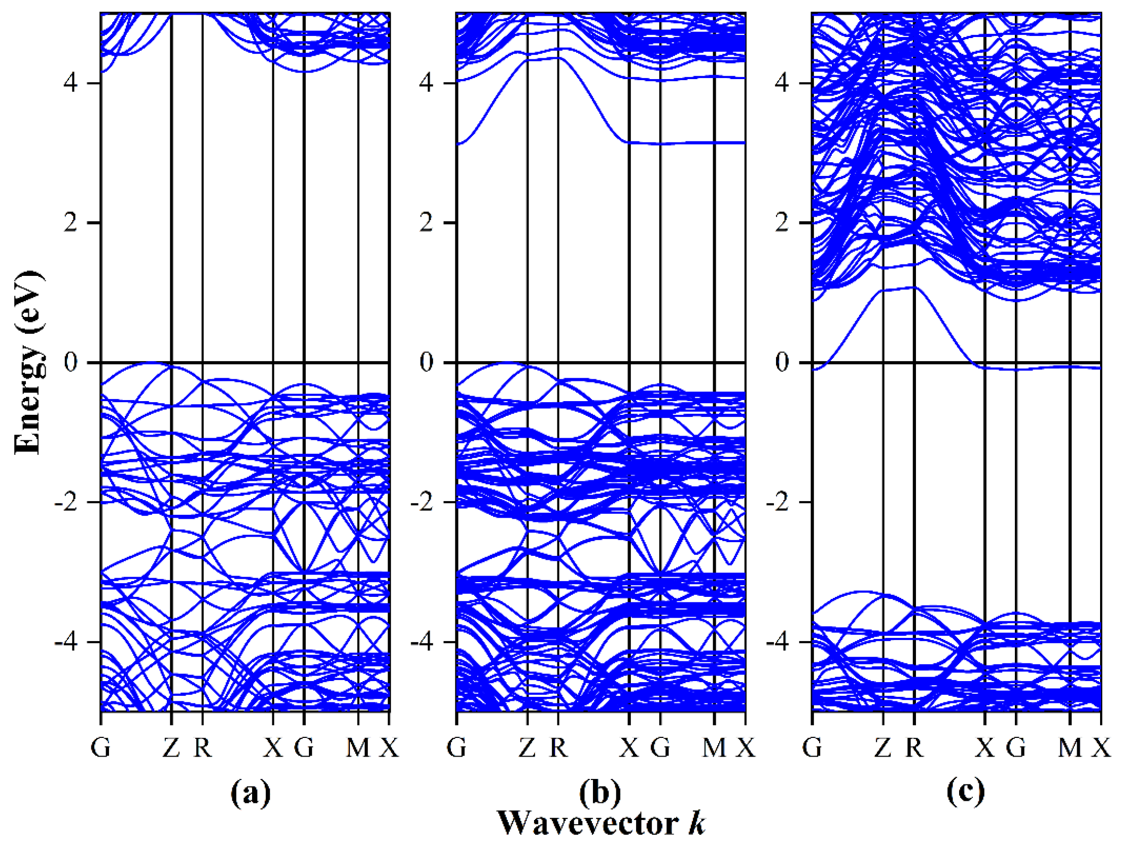
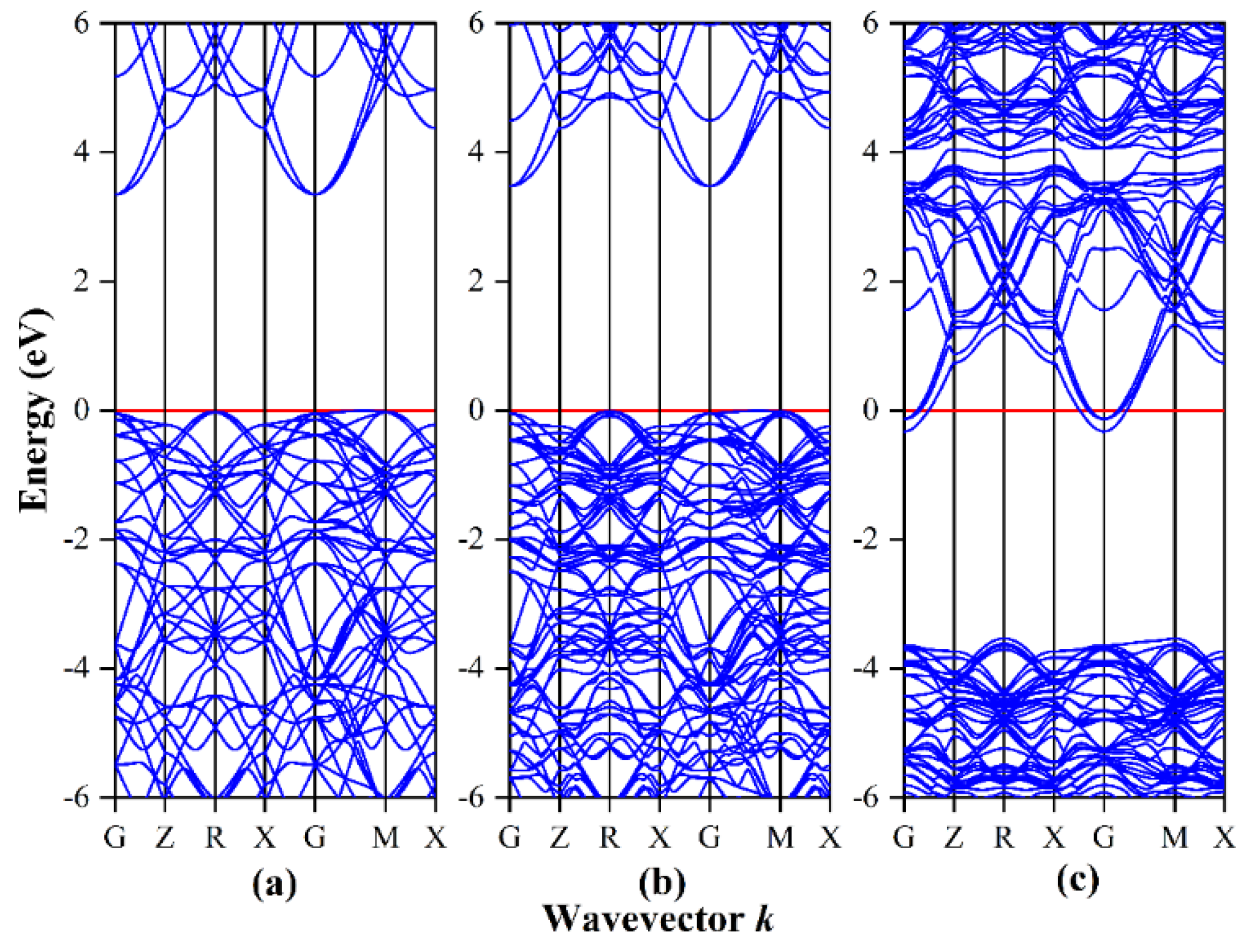
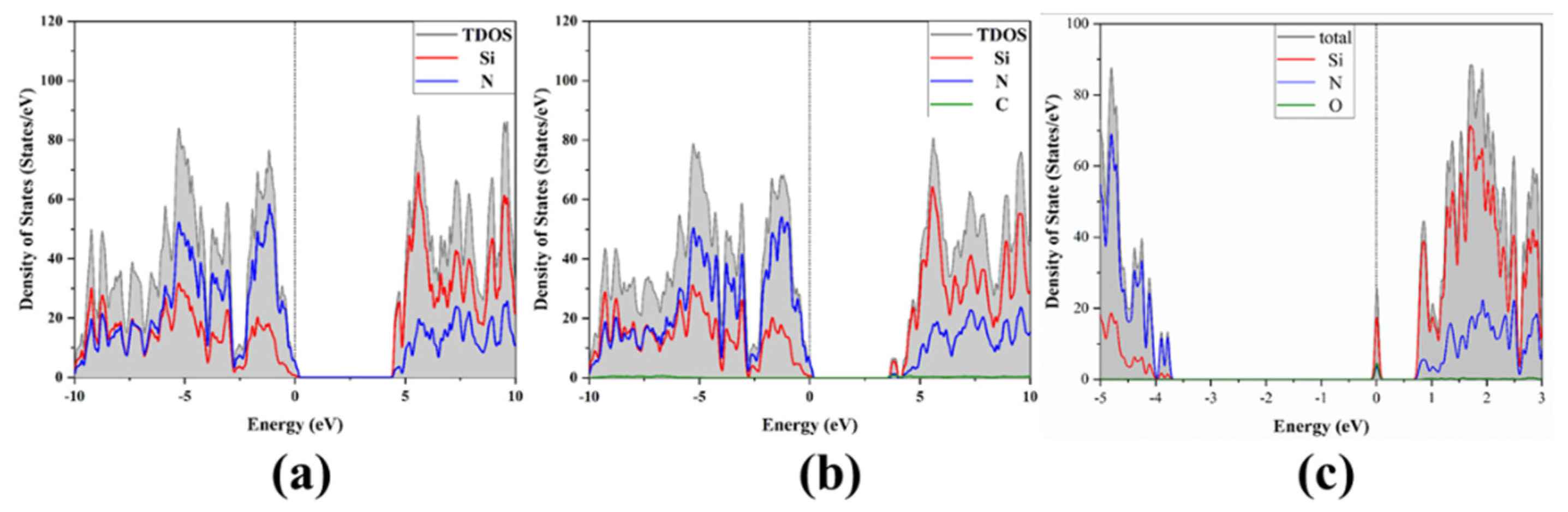
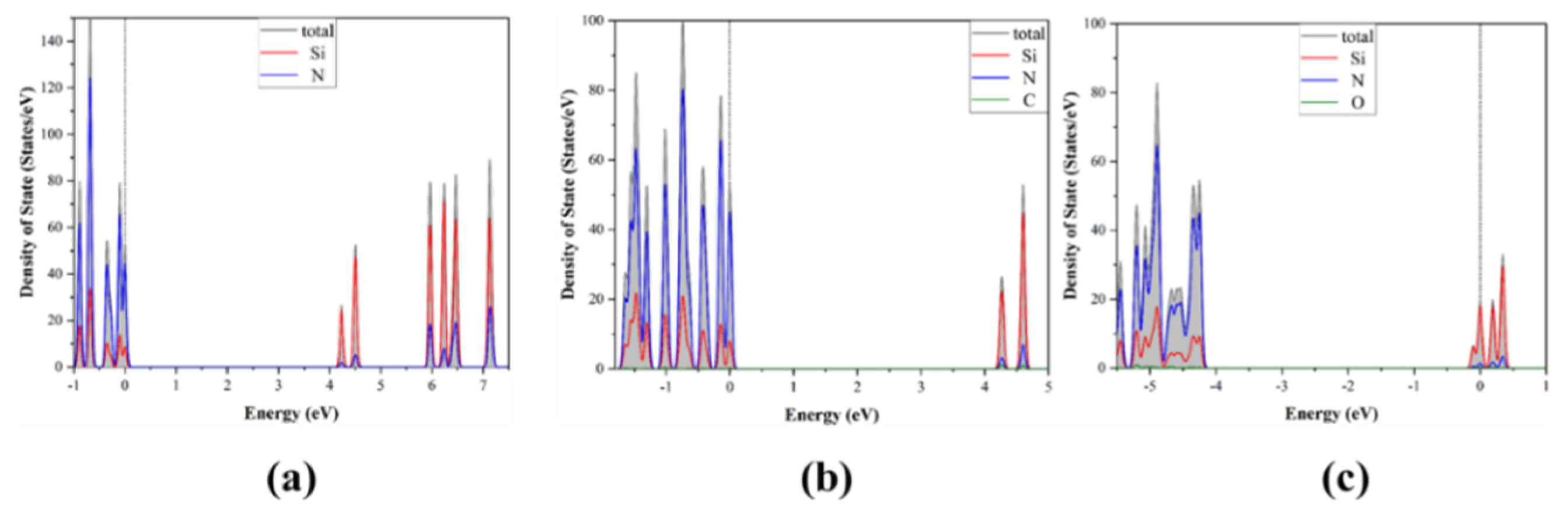
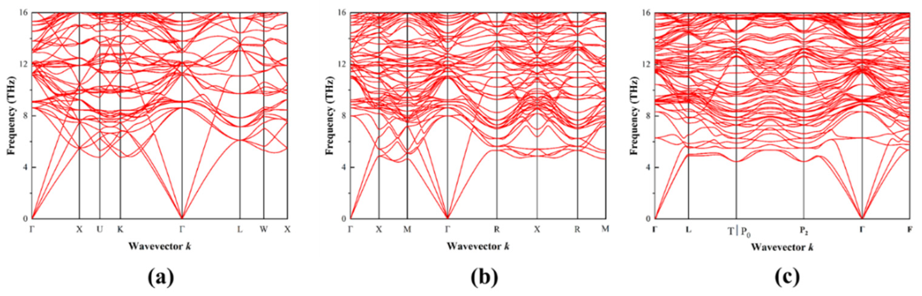
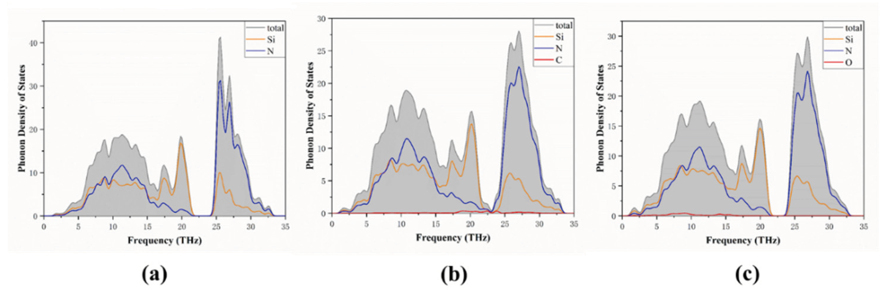
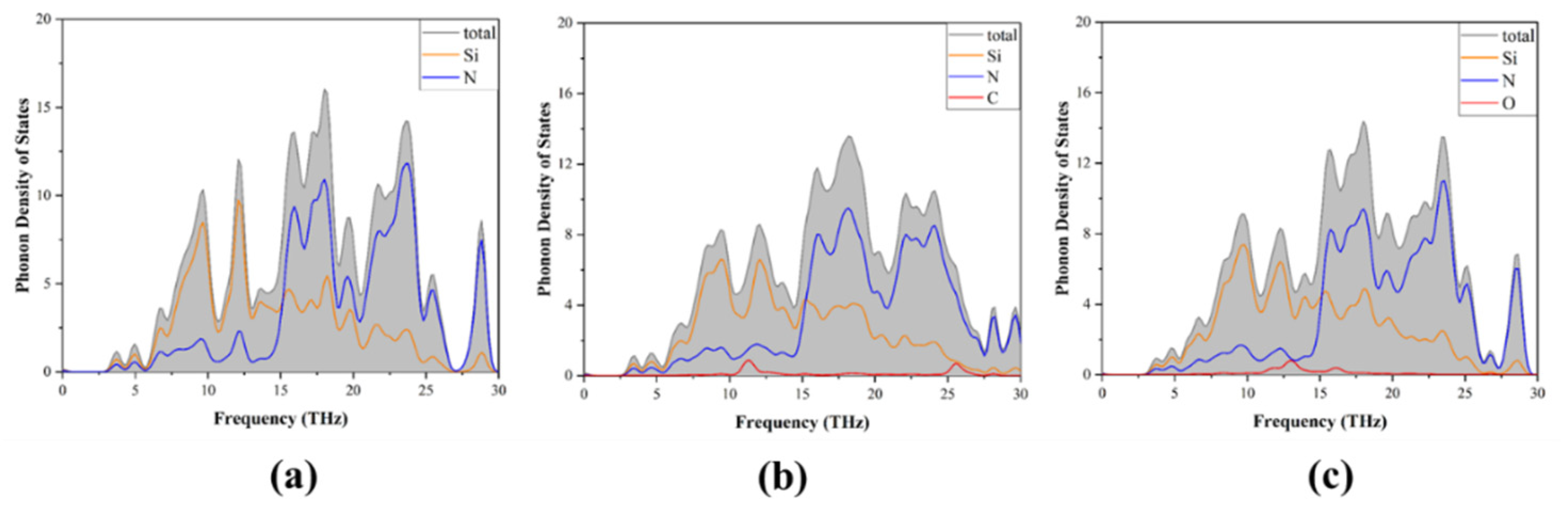
3.1. Band Structure and Density of States
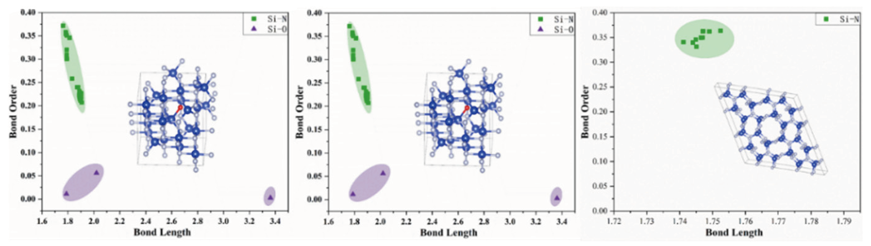
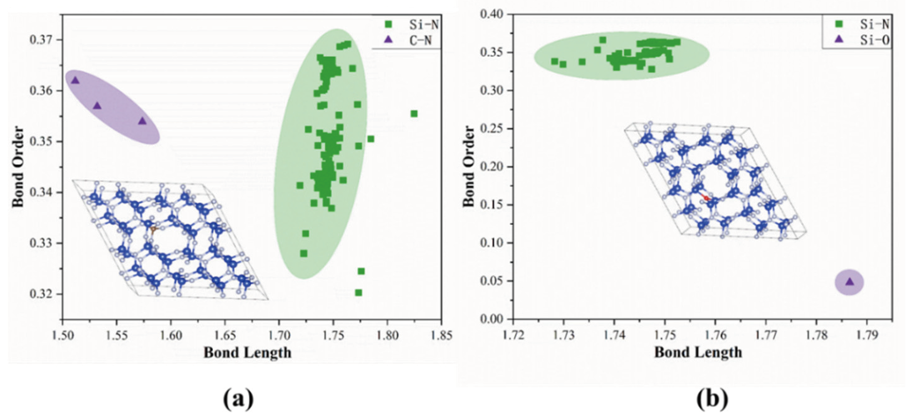
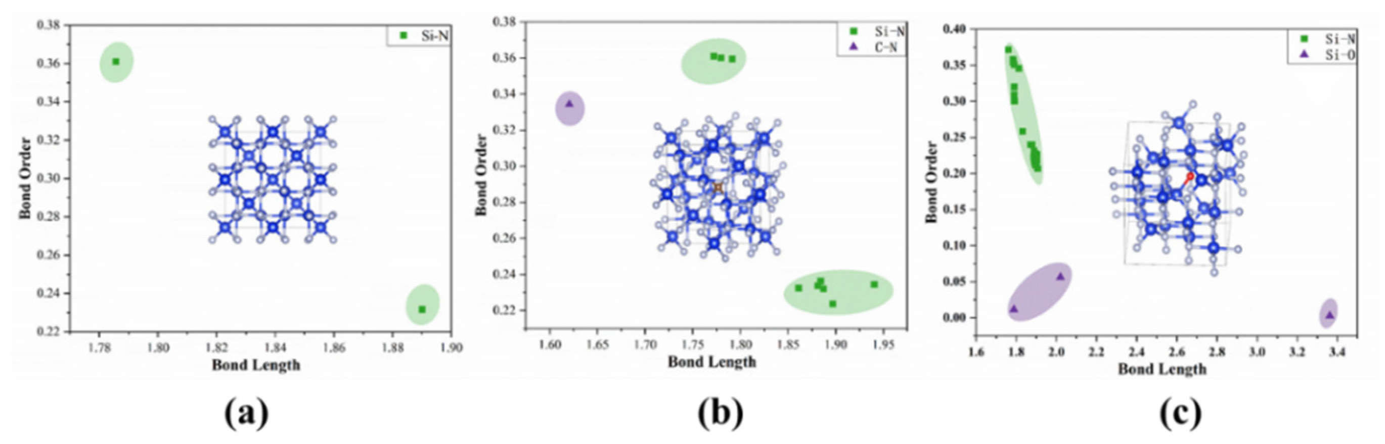
The application of density functional theory (DFT) provides a calculation of the ground state configuration, i.e., the structure at 0 K, where the GGA approximation underestimates the interaction between excited electrons. This results in an underestimation of the band gap. Following optimization using VASP software (6.3.2), the OLCAO method was used to calculate the energy band and the structural density of states.
The energy band structures of the six systems calculated along the high symmetry point of the Brillouin zone are presented in Figure 2 and Figure 3. As can be seen from Figure 2a, the direct band gap width of intrinsic β-Si3N4 is ca. 4.47 eV, which is close to the value (4.33 eV) calculated by Lu et al. [10]. Doping with C (Figure 2b) reduced the band gap of β-Si3N4, where the indirect band gap of 3.13 eV was also close to the value (2.90 eV) reported by Lu et al. [8]. The incorporation of C resulted in electrons occupying an increased number of energy levels. When compared with the intrinsic band structure of β-Si3N4, the Fermi level entered the conduction band after O doping (Figure 2c), making the doped nitride an n-type semiconductor material. The number of energy levels increased, and the bandgap width decreased (Eg = 3.20 eV). In the case of γ-Si3N4, the direct band gap was ca. 3.35 eV. Carbon doping (Figure 3b) slightly increased the band gap to 3.47 eV and significantly increased the number of energy levels occupied by electrons. Following the incorporation of O atoms (Figure 3c), the Fermi level entered the conduction band, γ-Si3N4 exhibited the characteristics of an n-type semiconductor, and the energy band accommodated electrons. The number of energy levels also increased with a smaller band gap width (Eg = 3.21 eV) (Figure 4 and Figure 5).

3.2. Bond Order

The bond order, or bond number, provides a numerical expression of the bonding strength of two adjacent atoms in the molecular orbital. It can be derived by calculating the number of electron cloud overlaps between atoms. The higher the bond level, the stronger the atomic bond, and the greater the crystal strength and stability. The bond levels of the six systems were calculated using OLCAO, and the results are shown in Figure 6, Figure 7 and Figure 8.
It can be seen from the bond length and bond order distribution plots that the contribution to the bond level of pure Si3N4 (Figure 6) was mainly due to Si-N bonds. The Si-N bonds in the β-form (Figure 7) were mainly distributed in the length range of 17.4–1.76, and the bond order fell between 0.325 and 0.375. The Si-N bond lengths in γ-Si3N4 (Figure 8) were ca. 1.79 and ca. 1.89, with a bond order of ca. 0.36 and ca. 0.23, associated with silicon–nitrogen tetrahedra and silicon–nitrogen octahedra. After doping with C and O atoms, the Si-O bond order was close to 0 for both the β- and γ-phases. The results reveal that the presence of lattice oxygen in the Si3N4 crystal results in a loss of bond order, reducing strength and stability. The incorporation of oxygen into the lattice results in a decrease in Si-N bond order in the two crystal forms to varying degrees, indicating differing levels of influence on bonding strength.
After the introduction of C atoms, although the bond order is changed slightly, the strength of the C-N bond that is formed is slightly lower than that of the Si-N bond, and the overall bonding strength is reduced. In terms of stability, the introduction of lattice oxygen should be avoided during the preparation of Si3N4 crystals. Moreover, the length of the C-N bond is lower than that of the Si-N bond, and the Si-O bond is longer than the Si-N bond. This can account for the changes in the unit cell parameters after the incorporation of C and O atoms.

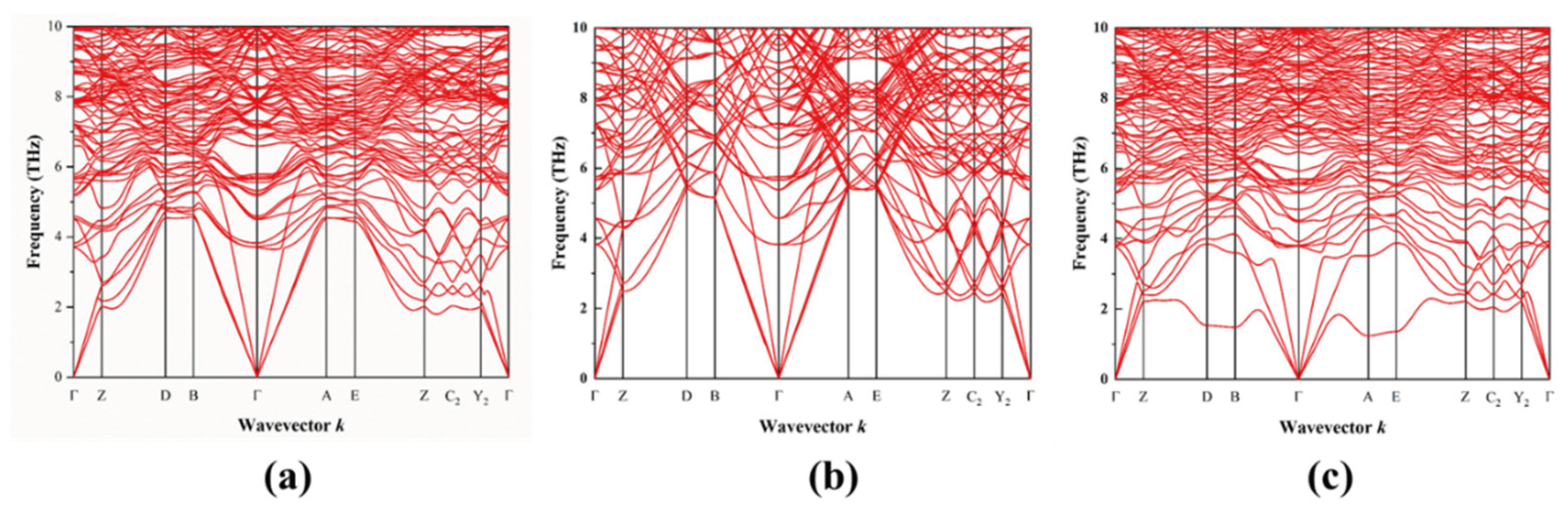
3.3. Phonon Properties

In order to assess the dynamic stability and thermal conductivity of the six configurations under consideration, the second-order force constant was calculated using first principles, and the associated phonon spectra and phonon density of states were obtained, as shown in Figure 9, Figure 10, Figure 11 and Figure 12. The phonon spectra did not include any imaginary frequencies, indicating that the systems exhibited dynamic stability.
There were three acoustic phonon branches in the phonon scattering profiles. Doping both β-Si3N4 and γ-Si3N4 with C and O atoms resulted in a reduction in the original acoustic branch frequency due to thermal conduction. The low-frequency phonons were the main contributors to the spectra with the participation of more phonons, resulting in a decrease in the thermal conductivity of the doped crystal lattice relative to the intrinsic β-Si3N4 and γ-Si3N4 crystals. The phonon density profiles for the β-Si3N4 (Figure 11) and γ-Si3N4 (Figure 12) systems exhibited contributions to the acoustic phonons and some low-frequency optical phonons due to the Si and N atoms. The introduction of C and O atoms had little impact on the overall phonon state density, a negligible effect on the low-frequency phonon branch, and a slight effect on the high-frequency region. Overall, the phonon spectra and phonon density of states analyses showed that the thermal conductivity of the intrinsic β-Si3N4 and γ-Si3N4 materials were reduced by C and O atom doping.

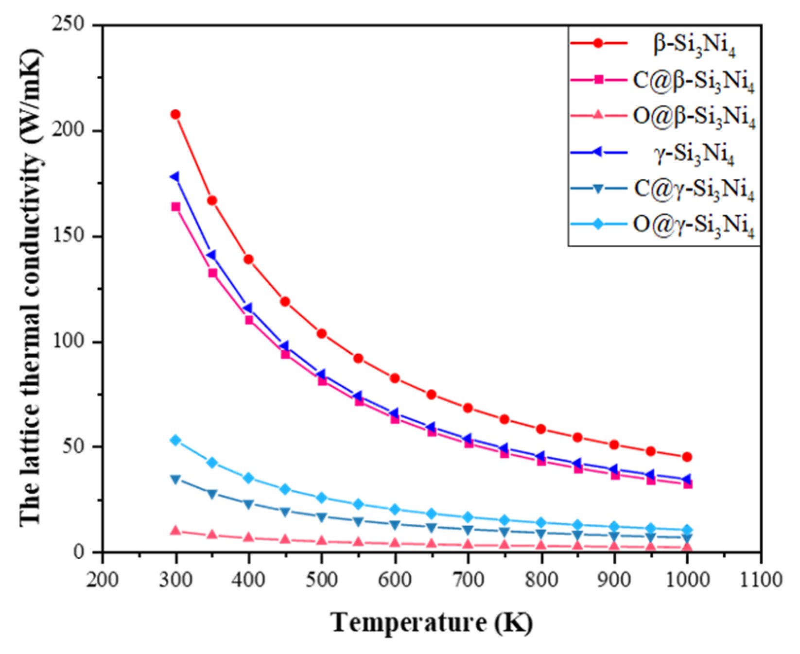
3.4. Thermal Properties

The total thermal conductivity (κt) of ceramic materials is equal to the sum of their electrical (κe) and lattice (κL) thermal conductivity, as follows:
κ t = κ e + κ L
κ e = L × σ × T
Here, κe is calculated using the Wiedemann–Franz law, σ is electrical conductivity and T is temperature. L usually takes the Sommerfeld value (L = 2.44 × 10⁻⁸ WΩK−2). However, the value of L is not a constant due to the influence of internal phonon–electron interactions. To rigorously evaluate heat conduction in more depth, the following sophisticated theoretical expression developed by Makinson was employed:
L t h = R 0 R e p h + T θ D 5 J 5 ( θ D T ) R 0 R e p h + T θ D 5 J 5 θ D T [ 1 + 3 π 2 k F q D 2 θ D T 2 1 2 π 2 J 7 ( θ D T ) J 5 ( θ D T ) ] L 0
where kF is the Fermi wave vector, θD is the Debye temperature, qD is the Debye wave vector, and k F q D = 2 1 3 is derived from free electron theory. J n θ D T is related to Debye and is defined as follows:
J n θ D T = 0 θ D T x n e x ( e x 1 ) 2 d x
where R0 reflects the extent of intrinsic disorder scattering and is the residual resistance at zero temperature, and Re−ph comes from electron–phonon scattering.
The calculated lattice thermal conductivities are presented in Figure 13. The theoretical values for β-Si3N4 and γ-Si3N4 were ca. 210 W/mK and 180 W/mK, respectively. The incorporation of O in β-Si3N4 serves to lower the thermal conductivity of the nitride to a significantly greater extent than that observed in the case of C doping. The incorporation of O in γ-Si3N4 also lowered thermal conductivity, but C doping lowered the value even further.

4. Conclusions

We used the first-principles method to calculate the electronic structure and phonon properties of β-Si3N4 and γ-Si3N4. The analysis revealed that O atom inclusion transforms the two crystal forms of Si3N4 into n-type semiconductors, accompanied by a reduction in the band gap, while C doping increases or decreases the band gap. In addition, the incorporation of lattice oxygen in β-Si3N4 or γ-Si3N4 serves to lower the thermal conductivity of the nitride, which is consistent with the conclusions drawn from the analytical experimental results. Doping with C also lowers thermal conductivity, and this effect is more pronounced than that of O doping in the case of γ-Si3N4.

Author Contributions

Conceptualization, Supervision, H.S.; Investigation, Validation, X.H.; Resources, X.L.; Writing—original draft, J.Q.; Writing—review & editing, J.Z. All authors have read and agreed to the published version of the manuscript.

Funding

This research received no external funding.

Data Availability Statement

Data is contained within the article.

Conflicts of Interest

The authors declare no conflict of interest.

References

  1. Riley, F.L. Silicon nitride and related materials. J. Am. Ceram. Soc. 2010, 83, 245–265. [Google Scholar] [CrossRef]
  2. Lin, H.; Ferber, M. Mechanical reliability evaluation of silicon nitride ceramic components after exposure in industrial gas turbines. J. Eur. Ceram. Soc. 2002, 22, 2789–2797. [Google Scholar] [CrossRef]
  3. Haggerty, J.S.; Lightfoot, A. Opportunities for enhancing the thermal conductivities of SiC and Si3N4 ceramics through improved processing. In Proceedings of the 19th Annual Conference on Composites, Advanced Ceramics, Materials, and Structures—A: Ceramic Engineering and Science Proceedings, Cocoa Beach, FL, USA, 8–12 January 1995; Volume 16, pp. 475–487. [Google Scholar]
  4. Zhu, X.W.; Sakka, Y.; Zhou, Y.; Hirao, K.; Itatani, K. A Strategy for Fabrication Textured Silicon Nitride with Enhanced Thermal Conductivity. J. Eur. Ceram. Soc. 2014, 34, 2585–2589. [Google Scholar] [CrossRef]
  5. Watari, K. High thermal conductivity non-oxide ceramics. J. Ceram. Soc. Jpn. 2001, 109, S7–S16. [Google Scholar] [CrossRef]
  6. Kitayama, M.; Hirao, K.; Toriyama, M.; Kanzaki, S. Thermal conductivity of β-Si3N4: I, effects of various microstructural factors. J. Am. Ceram. Soc. 1999, 82, 3105–3112. [Google Scholar] [CrossRef]
  7. Yokota, H.; Ibukiyama, M. Effect of lattice impurities on the thermalconductivity of β-Si3N4. J. Eur. Ceram. Soc. 2003, 23, 55–60. [Google Scholar] [CrossRef]
  8. Lu, H.H.; Huang, J.L. Microstructure in Silicon Nitride Containing b-Phase Seeding: III, Grain Growth and Coalescence. J. Am. Ceram. Soc. 2001, 84, 1891–1895. [Google Scholar] [CrossRef]
  9. Yokota, H.; Ibukiyama, M. Microstructure Tailoring for High Thermal Conductivity of β-Si3N4 Ceramics. J. Am. Ceram. Soc. 2003, 86, 197–199. [Google Scholar] [CrossRef]
  10. Zhu, X.; Zhou, Y.; Hirao, K. Effects of processing method and additivecomposition on microstructure and thermal conductivity of Si3N4 ceramics. J. Eur. Ceram. Soc. 2006, 26, 711–718. [Google Scholar] [CrossRef]
  11. Hirao, K.; Watari, K.; Hayashi, H.; Kitayama, M. High thermal conductivity silicon nitride ceramic. MRS Bull. 2001, 26, 451–455. [Google Scholar] [CrossRef]
  12. Zhu, X.; Zhou, Y.; Hirao, K.; Ishigaki, T.; Sakka, Y. Potential use of only Yb2O3 in producing dense Si3N4 ceramics with high thermal conductivity by gas pressure sintering. Sci. Technol. Adv. Mater. 2010, 11, 065001. [Google Scholar] [CrossRef] [PubMed]
  13. Ishibe, T.; Kaneko, T.; Uematsu, Y.; Sato-Akaba, H.; Komura, M.; Iyoda, T.; Nakamura, Y. Tunable Thermal Switch via Order–Order Transition in Liquid Crystalline Block Copolymer. Nano Lett. 2022, 22, 6105–6111. [Google Scholar] [CrossRef] [PubMed]
  14. Zeidell, A.M.; Filston, D.S.; Waldrip, M.; Iqbal, H.F.; Chen, H.; McCulloch, I.; Jurchescu, O.D. Large-area uniform polymer transistor arrays on flexible substrates: Towards high-throughput sensor fabrication. Adv. Mater. Technol. 2020, 5, 2000390. [Google Scholar] [CrossRef]
  15. Becher, P.F.; Painter, G.S.; Shibata, N.; Waters, S.B.; Lin, H.T. Effects of Rare-earth(RE) intergranular adsorption on the phase transformation, microstructureevolution, and mechanical properties in silicon nitride with RE2O3 + MgO additives: RE = La, Gd, and Lu. J. Am. Ceram. Soc. 2008, 91, 2328–2336. [Google Scholar] [CrossRef]
  16. Xiang, H.; Feng, Z.; Li, Z.; Zhou, Y. Theoretical predicted high-thermal-conductivity cubic Si3N4 and Ge3N4: Promising substrate materials for high-power electronic devices. Sci. Rep. 2018, 8, 14374. [Google Scholar] [CrossRef] [PubMed]
Figure 1. Crystal structure of β-Si3N4 and γ-Si3N4.
Crystals 14 00549 g001
Figure 2. Energy band diagrams of (a) β-Si3N4, (b) C@β-Si3N4, and (c) O@β-Si3N4.
Crystals 14 00549 g002
Figure 3. Energy band diagrams of (a) γ-Si3N4, (b) C@γ-Si3N4, and (c) O@γ-Si3N4.
Crystals 14 00549 g003
Figure 4. (a) β-Si3N4, (b) C@β-Si3N4, and (c) O@β-Si3N4 density of states plots.
Crystals 14 00549 g004
Figure 5. (a) γ-Si3N4, (b) C@γ-Si3N4, and (c) O@γ-Si3N4 density of states plots.
Crystals 14 00549 g005
Figure 6. β-Si3N4 bond length and bond order distribution plots.
Crystals 14 00549 g006
Figure 7. (a) C@β-Si3N4 and (b) O@β-Si3N4 bond length and bond order distribution plots.
Crystals 14 00549 g007
Figure 8. (a) γ-Si3N4, (b) C@γ-Si3N4, and (c) O@γ-Si3N4 bond length and bond order distribution plots.
Crystals 14 00549 g008
Figure 9. (a) β-Si3N4, (b) C@β-Si3N4, and (c) O@β-Si3N4 phonon spectra.
Crystals 14 00549 g009
Figure 10. (a) γ-Si3N4, (b) C@γ-Si3N4, and (c) O@γ-Si3N4 phonon spectra.
Crystals 14 00549 g010
Figure 11. (a) β-Si3N4, (b) C@β-Si3N4, and (c) O@β-Si3N4 phonon density of states profiles.
Crystals 14 00549 g011
Figure 12. (a) γ-Si3N4, (b) C@γ-Si3N4, and (c) O@γ-Si3N4 phonon density of states profiles.
Crystals 14 00549 g012
Figure 13. Lattice thermal conductivity as a function of temperature for the six configurations.
Crystals 14 00549 g013
Table 1. Optimized structural geometric parameters.
Crystal Forma/Åb/Åc/ÅV/Å3
β-Si3N415.31915.3195.8501188.834
C@β-Si3N415.25915.2745.8341177.650
O@β-Si3N415.33415.3335.8501192.140
γ-Si3N47.7877.7877.787472.263
C@γ-Si3N47.7427.7427.742463.991
O@γ-Si3N47.7997.7997.799474.300
Disclaimer/Publisher’s Note: The statements, opinions and data contained in all publications are solely those of the individual author(s) and contributor(s) and not of MDPI and/or the editor(s). MDPI and/or the editor(s) disclaim responsibility for any injury to people or property resulting from any ideas, methods, instructions or products referred to in the content.

