Article

The Effect of Varying Parameters of Laser Surface Alloying Post-Treatment on the Microstructure and Hardness of Additively Manufactured 17-4PH Stainless Steel

by
Alexander S. Chaus
1,*,
Oleg G. Devoino
2,
Martin Sahul
1,
Ľubomír Vančo
1 and
Ivan Buranský
1
1
Faculty of Materials Science and Technology in Trnava, Slovak University of Technology in Bratislava, J. Bottu 25, 917 24 Trnava, Slovakia
2
Faculty of Mechanical Engineering, Belarusian National Technical University, Khmelnitsky Str., 9, Build. 6, 220013 Minsk, Belarus
*
Author to whom correspondence should be addressed.
Crystals 2024, 14(6), 569; https://doi.org/10.3390/cryst14060569
Submission received: 4 June 2024 / Revised: 13 June 2024 / Accepted: 17 June 2024 / Published: 20 June 2024
(This article belongs to the Special Issue Advances in Surface Modifications of Metallic Materials)

Abstract

:
In the present work, the evolution of the microstructure in additively manufactured 17-4PH stainless steel, which was subjected to laser surface alloying with amorphous boron and nitrogen at the varying process parameters, was studied. The main aim was to improve surface hardness and hence potential wear resistance of the steel. Scanning electron microscopy, wavelength-dispersive X-ray spectroscopy (WDS), and Auger electron spectroscopy (AES) were used. It was shown that the final microstructure developed in the laser-melted zone (LMZ) is dependent on a variety of processing parameters (1 and 1.5 mm laser beam spot diameters; 200, 400, and 600 mm/min laser scan speeds), which primarily influence the morphology and orientation of the eutectic dendrites in the LMZ. It was metallographically proven that a fully eutectic microstructure, except for one sample containing 60 ± 4.2% of the eutectic, was revealed in the LMZ in the studied samples. The results of WDS and AES also confirmed alloying the LMZ with nitrogen. The formation of the boron eutectic and the supersaturation of the α-iron solid solution with boron and nitrogen (as a part of the eutectic mixture) led to enhanced microhardness, which was significantly higher compared with that of the heat-treated substrate (545.8 ± 12.59–804.7 ± 19.4 vs. 276.8 ± 10.1–312.7 ± 11.7 HV0.1).

1. Introduction

For different industrial applications, steels are of great importance and interest owing to the huge variety in their microstructure and properties [1]. 17-4PH stainless steel containing ferrite-forming and austenite-forming elements, such as Cr, Si, Nb, Mo, Ni, Cu, respectively [2], is the most well-known representative of the so-called precipitation hardening martensitic stainless steels [3,4]. During aging, the fine particles of copper precipitate from the supersaturated martensite, thus providing a strengthening effect in the steel, which can vary significantly, depending on the definite conditions within the range of possible heat treatments designed for this steel [2]. Therefore, the heat-treated parts manufactured by 17-4PH stainless steel by traditional technologies and exhibiting primarily high strength in combination with excellent corrosion resistance and high toughness have been widely used in many industrial applications, including the airspace industry [5]. However, the disadvantage of this type of steel is its relatively low hardness and hence insufficient wear resistance, which is not suitable for certain applications. Consequently, attempts have been made to improve some mechanical properties of the steel using a variety of surface treatments in order to modify its surface microstructure and appropriate properties, primarily surface hardness and wear resistance. For this purpose, different methods have been used: a low-temperature plasma surface treatment [6], plasma nitrocarburizing [7], an ultrasonic surface rolling process [8,9], grit blasting and the development of coatings [10,11], and a laser surface treatment [12,13,14,15]. In this context, it is worth mentioning that among the used methods, laser surface alloying is one of the most widely used. This is primarily attributed to its high impact on the modification and evolution of the surface microstructure, which results in a significant improvement of hardness and wear resistance of a developed surface layer. Consequently, surface laser alloying is widely used not only for different stainless steels, such as 1.4550 [12], 17-4PH [14], and 316L [16,17], but also for a variety of other steels, for example, 41Cr4 steel [18], C45 steel [19], 145Cr6 tool steel [20], Vanadis-6 tool steel [21,22], and so on. The use of amorphous boron is important in laser surface alloying, and this has been confirmed in the above-cited works and some others [23,24].
The 17-4PH grade currently seems to be the most studied precipitation-hardening stainless steel used in additive manufacturing [25], in which the microstructure and properties in the additively manufactured state have been thoroughly investigated in the works published in the last few years in relation to different technologies, primarily selective laser melting [26,27,28,29] and material extrusion [30]. In addition to this obviously increased interest in post-treatments, focusing primarily on surface quality improvement should be also mentioned. Known post-processing techniques include mechanical polishing and PVD coating [31], surface mechanical attrition treatment [32], and post-heat treatment [33]. These can be explained by the well-known fact that the as-built surface of additively manufactured parts is not smooth enough to meet the surface quality requirements in some applications [34]. In contrast, our previous work has shown that greater surface roughness of additively manufactured 17-4PH stainless steel samples can be advantageous from a laser surface alloying point of view [35]. In particular, for the first time, our previous work has demonstrated that the character of the surface topography, and hence the surface roughness of the additively manufactured samples of the given steel, had a crucial effect on the microstructure evolution during laser surface alloying using the pre-placed layer of amorphous boron. After the same laser surface treatment of the given steel, a dramatic difference in the microstructure and microhardness of the samples with smooth and rough as-built surfaces was found, and the measurements proved the superior microhardness of the samples with rough surfaces. Additionally, the alloying of the LMZ with nitrogen at a permanent flow of the compressed air to the laser beam interaction zone was also proven, which had not been previously reported in the scientific literature. However, the given relations were established for the samples subjected to the laser surface alloying using only one set of the fixed processing parameters, i.e., a 1 mm laser beam spot diameter and a laser scan speed of 400 mm per min. In this regard, it is worth noting that the main problem in relation to laser surface alloying is the selection of the proper process parameters to obtain the most desirable results, as reported in [36]. Given this, the objective of the present paper is to study the effect of varying parameters of the laser surface alloying post-treatment on the microstructure evolution and surface hardening in the so-called rough samples of additively manufactured 17-4PH stainless steel to improve its wear resistance in the future.

2. Materials and Methods

2.1. Material and Sample Manufacturing

The bound metal rods containing 17-4PH stainless steel powder together with the wax and polymer binder were used for the green specimen fabrication on a Desktop Metal Studio System Printer (Burlington, MA, USA) using the Bound Metal Deposition™ print technology. The following printing parameters were used to manufacture samples with a size of 22 × 20 × 5 mm: a printing layer of 0.15 mm, 3 contours (1.44 mm), a thickness of the upper and lower walls of 1.8 mm, and an infill of 17.14%. To produce needed surface relief on the samples, the material was extruded on the raft. The initial microstructure of the raft surface was formed in a similar way as in the case of the samples but extruded much larger single filaments on the surface. Finally, the surface of the raft was coated with a thin layer of ceramics up to 150 μm to prevent surface cohesion when sintering at high temperatures and provide easier separation after sintering. After the 3D printing, the samples were immersed in debinding fluid to remove the binder by chemical dissolution. Then, the samples were sintered in a shielding atmosphere using a mixture of gases: 97% argon and 3% hydrogen. The sintering process involved holding at 1360 °C for 2 h in a sintering furnace and slow furnace cooling to a temperature of about 30 °C. Finally, the samples were heat treated using solution treatment at 1040 °C for 30 min, air cooling followed by aging at 621 °C for 4 h, and air cooling.

2.2. Laser Surface Alloying

Laser surface alloying was performed on a laser technological complex based on “Comet 2”, a continuous wave CO2 laser with a power of 1.2 kW. The radiation wavelength was 10.6 μm. The varying laser parameters, i.e., a laser beam spot diameter of 1 and 1.5 mm and a laser scan speed of 200, 400, and 600 mm per min, were adopted for the samples. Given this, the samples were marked as follows: 1/200, 1/400, 1/600, 1.5/200, 1.5/400, and 1.5/600, where 1 and 1.5 are the laser beam spot diameters (mm); 200, 400, and 600 are the laser scan speeds (mm/min). Prior to the laser processing, a thin layer of amorphous boron with a thickness in the range of 0.1–0.15 mm was deposited on sample surfaces. To protect laser optics from pollution and provide alloying for the molten pool with nitrogen, the permanent flow of compressed air to the beam interaction zone was used.

2.3. Characterization of the Samples

The microstructure of the samples was studied on a JEOL JSM–7600F scanning electron microscope. The wavelength-dispersive X-ray spectroscopy (WDS) facilities were used for quantitative analysis. The amount of the eutectic in the LMZ in the samples was determined using the statistical processing method described elsewhere [37]. The Auger electron spectroscopy (AES) analysis was performed using the JEOL JAMP 9510-F field emission Auger microprobe under the conditions described elsewhere [35]. A Zeiss LSM 700 laser scanning confocal microscope was used to evaluate the topography and roughness of the samples. The quantitative results of the sample roughness profile and height parameter measurements were as follows: Ra 12 μm and Rz 55 μm and Sa 29.9 μm. The microhardness of the samples was measured using a Buehler IndentaMet 1105 with a maximal load of 0.98 N (HV0.1) and a dwell time of 10 s. An average value of microhardness was calculated using ten measurements. A flowchart of the methodology applied in this study is presented in Figure 1.

3. Results and Discussion

3.1. General Characterisation of the Laser-Affected Zone

It is well-known that, after laser surface remelting, two principal areas can be always distinguished in the so-called laser-affected zone (LAZ) formed in a substrate, i.e., a laser-melted zone (LMZ) and a heat-affected zone (HAZ) [38,39,40]. Sometimes, the so-called transition zone (TZ) with partially remelted metal can be also observed in the LAZ, between the LZM and the HAZ [41]. The LAZ, typical for the present work, is shown in Figure 2a.
Generally, the depth of the LMZ primarily depends on the laser power density (the laser beam spot diameter), the scan speed increase with the increase in laser power density, and the decrease in the scan speed, as confirmed, for example, in the two independent works by Chaurasia et al. [42] and Leech [43]. A comparison of the LMZ depth changes owing to the varying laser beam spot diameter and laser scan speed indicates that all samples treated using the 1 mm laser beam spot diameter exhibited a greater depth in the LMZ than the corresponding samples treated using the 1.5 mm laser beam spot diameter. This can be explained by a lower laser power density input, and hence there were softer thermal conditions when the laser beam spot diameter was 1.5 mm. Overall, the depth of the LMZ in all studied samples decreases with increasing the scan speed, as can be seen in Table 1. This is consistent with the results reported in [42,43].
It is well-known that tensile stresses developed during laser treatment can initiate cracks in the cross-section of the LMZ. When the plasticity of the material is too low to provide stress relaxation, cracks can propagate through the entire LMZ into the bonding zone [44,45] and even into the substrate [46]. In this context, it is important to note that no cracks were detected in the LMZ in all studied samples.
The microstructure of the unaffected steel substrate was a mixture of relatively large ferrite grains and the products of austenite transformation, i.e., martensite, as shown in Figure 2b.

3.2. Microstructure Characterization of the Samples That Were Alloyed Using a 1 mm Laser Beam Spot Diameter

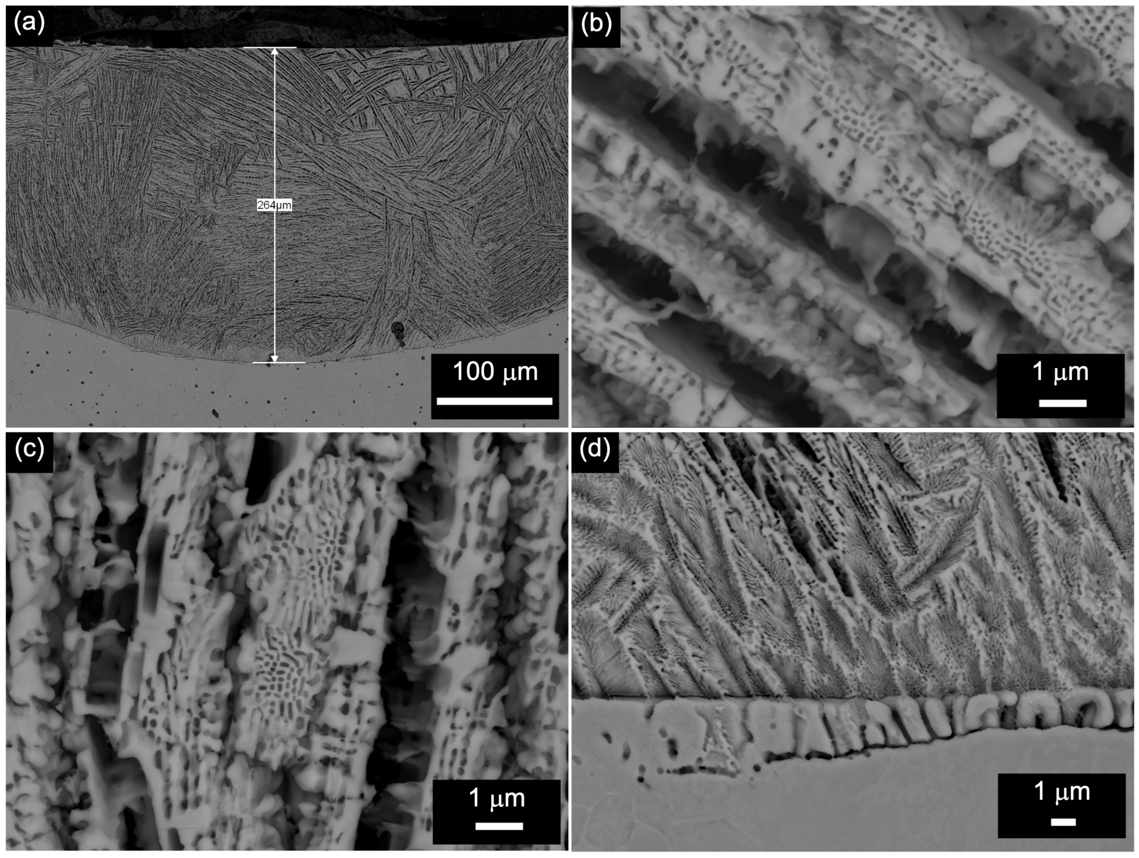
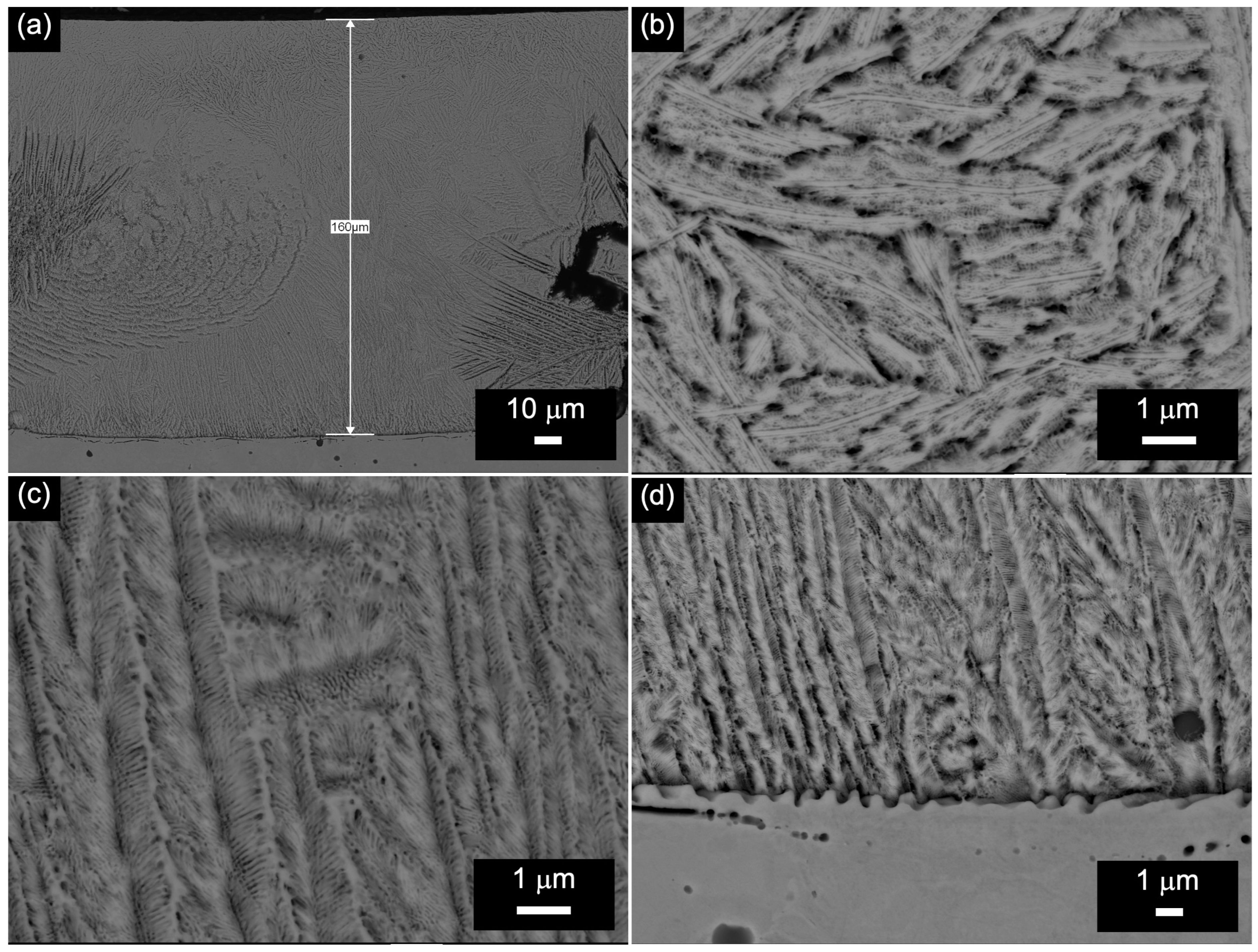
The microstructure of the 1/200 sample subjected to surface alloying at a scan speed of 200 mm/min and a laser beam spot diameter of 1 mm is presented in Figure 3. It is seen that only eutectic structures solidified in the whole LZM of the sample, as illustrated in Figure 3a and Table 2. It is very interesting that Monisha et al. reported that no eutectic was revealed in the LMZ when the laser surface alloying with boron was applied to titanium [47]. In contrast, in the LMZ, they observed coarse dendrites, which represented the TiB2 formation, and/or more fine precipitates of a predominantly needle-like shape formed by TiB.
Eutectic-preferred growth directions were different in individual regions of the LMZ. Whereas in the upper region of the LMZ, the eutectic structure was found to be inclined at some 45° to the surface (Figure 3b), in the middle region, the dendrites were aligned almost either normally (Figure 3c) or parallel to the surface, as shown in Figure 3a. Such features can be attributed to strong melt stirring in the pool under the effect of laser processing.
It is worth noting that, in this case, the microstructural features of the formed eutectic (Figure 3b,c) were somehow comparable to that of the ledeburite eutectic formed in white irons. Nevertheless, a significantly finer eutectic was revealed at the very bottom of the LMZ in the 1/200 sample, as shown in Figure 3d. Figure 3d also shows an interface between the LMZ and the substrate well seen at a high magnification. Moreover, in some places along the interface, a very thin transition layer (about 3 μm), formed by a single line of partially melted grains of the substrate, was also observed in this sample, as seen in Figure 3d.
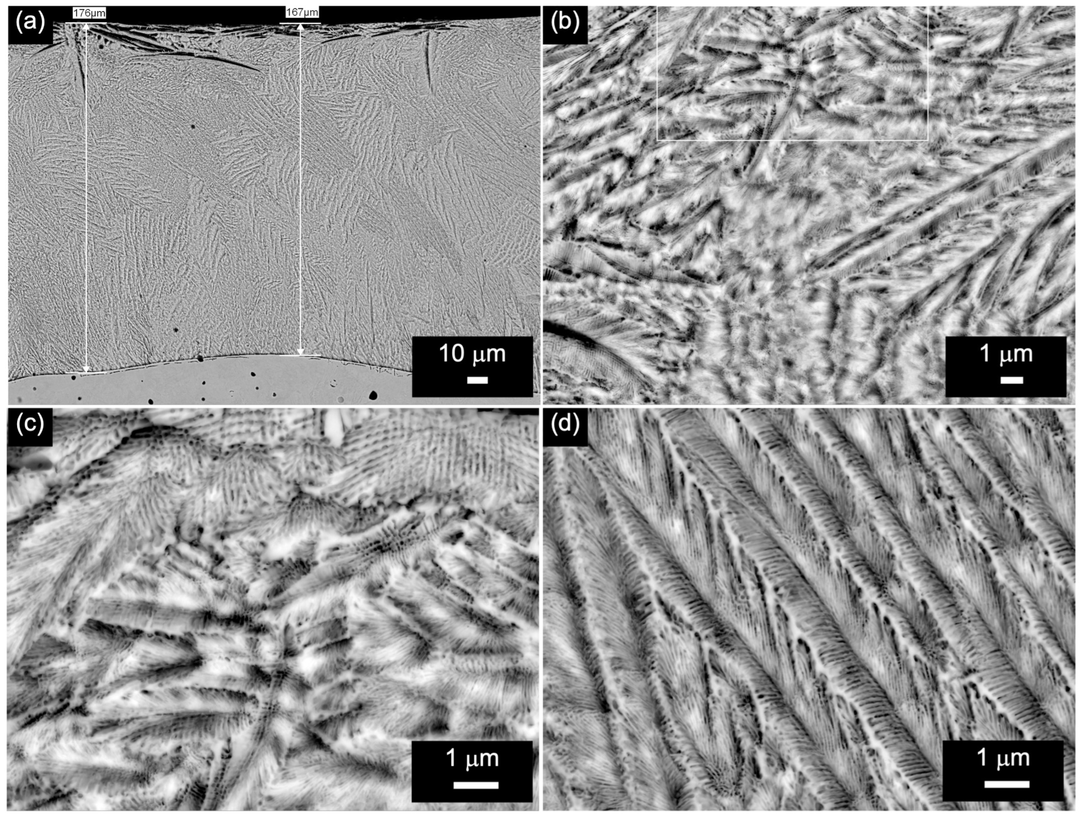
The microstructure of the LMZ in the 1/400 sample is shown in Figure 4. The LMZ in this sample appeared to only solidify into a structure completely consisting of eutectics. In the upper region of the LMZ, the eutectic is formed by the extremely fine, short feather-like dendrites, as shown in Figure 4b,c. The secondary and tertiary side arms of these eutectic dendrites have nano-sized cross-sections of the order of 100 nm and less, as shown in Figure 4c. In the middle and bottom regions of the LMZ, long slender feather-like eutectic dendrites solidified, as illustrated in Figure 4d. In this case, secondary and tertiary side arms are a bit larger than in the previous case; nevertheless, their length did not exceed 1 μm, as can be seen in Figure 4d. It is interesting that long eutectic dendrites exhibiting similar feather-like morphology, however, formed by chromium-rich carbides, were revealed in the LMZ in the 1Cr18Ni9Ti stainless steel subjected to the laser surface alloying with Mn + Cr3C2 and Mn + NiCr-C powders [48].
Figure 4a shows that a clearly visible interface between the LMZ and substrate was formed in the 1/400 sample. In the given sample, a variety of eutectic dendrite orientations in the LMZ are seen in Figure 4a.
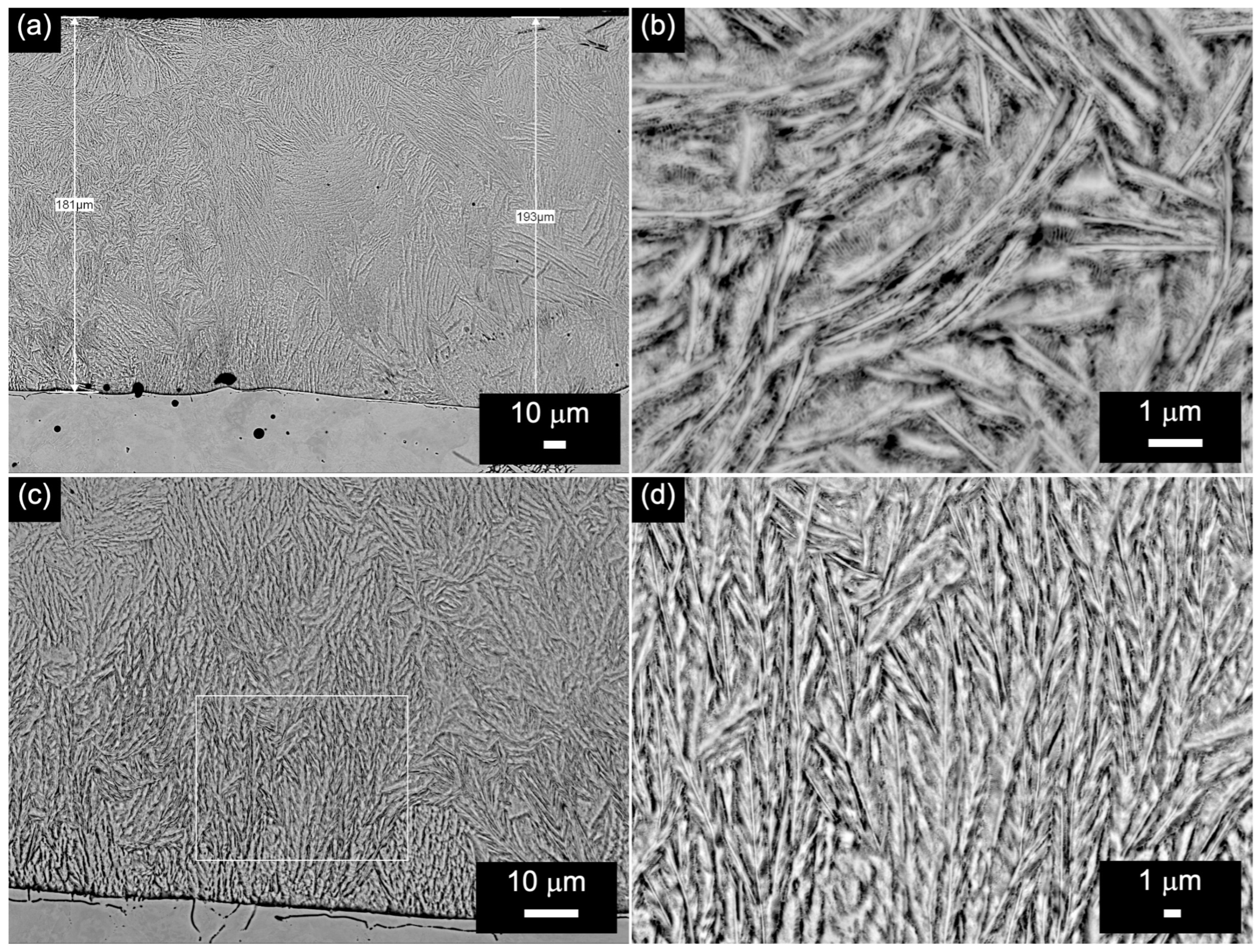
Figure 5 shows the main features of the LMZ microstructure in the 1/600 sample. Visually, the microstructure was found to be somehow comparable to that of the 1/400 sample, as seen in Figure 4. It is seen that in the 1/600 sample, the fully eutectic microstructure of the LMZ is also formed by feather-like eutectic dendrites, as illustrated in Figure 5a,c.
Nevertheless, their morphology was a bit different. For example, in the upper region of the LMZ, the curved extremely fine feather-like dendrites with clearly distinguished trunks were formed during solidification, as shown in Figure 5b. In the bottom region of the LMZ, extremely fine feather-like dendrites were also formed; however, they had somewhat longer trunks, as shown in Figure 5c,d. Figure 5a,c illustrate that the orientation of eutectic dendrites in the LMZ is mostly random.
It is worth noting that the metallographic investigations experimentally proved the development of a fully eutectic microstructure in the LMZ in the samples in the entire range of the used scan speeds when the laser beam spot diameter was 1 mm.

3.3. Microstructure Characterization of the Samples That Were Alloyed Using a 1.5 mm Laser Beam Spot Diameter

The microstructure of the LMZ in the 1.5/200 sample is shown in Figure 6. In general, a very fine eutectic structure was revealed in this sample, especially in the upper (Figure 6a,b) and bottom (Figure 6a,d) regions of the LMZ. On the other hand, the feather-like dendrites, formed within the lower part of the middle region in the case of the 1.5/200 sample, seem to be a bit coarser, as shown in Figure 6c. The orientation of the eutectic dendrites in some areas of the LMZ is mostly random, as documented in Figure 6.
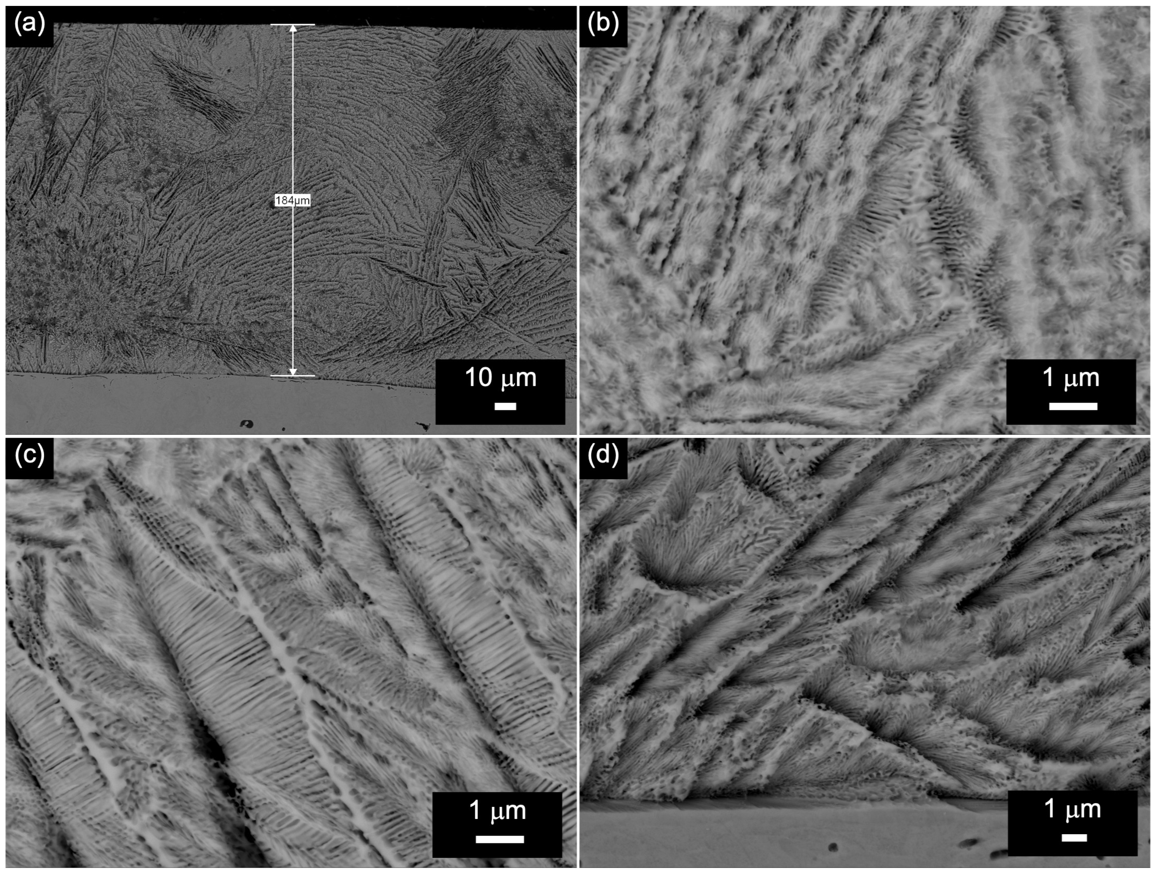
Figure 7 shows the microstructure of the LMZ in the 1.5/400 sample. As can be seen in Figure 7a, the LMZ microstructure is fully eutectic, where two types of eutectic dendrites are observed. In the upper region of the LMZ, extremely fine feather-like dendrites with clearly distinguished trunks were revealed, as shown in Figure 7b. In contrast, in the middle (Figure 7c) and bottom (Figure 7d) regions of the LMZ, long slender feather-like eutectic dendrites were formed during solidification. In general, Figure 7 demonstrates that eutectic dendrites are randomly oriented in the LMZ in this sample.
Figure 8 illustrates the microstructure of the LMZ in the 1.5/600 sample, in which, in contrast to all the previous samples, the formation of solid solution dendrites occurred during solidification. Consequently, compact irregular and elongated dendrites, both unbranched and slightly branched (Figure 8a,b), on the one hand, and compact equiaxed and elongated, as well as columnar and coarse branched ones (Figure 8a,c), on the other hand, are observed in the upper and lower parts of the middle region, respectively. As presented in Figure 8d,e, at the right side of the middle region of the LMZ, the microstructure in the 1.5/600 sample consisted of the long slender feather-like eutectic dendrites, whose trunks appeared to be thick and twined, as seen in Figure 8d,e. Moreover, some of those dendrites were a bit curved, and their twined trunks were sometimes found to be broken (see the left and right sides of the micrograph in Figure 8e). The latter can be attributed to the deformation of dendrites during solidification due to the stirring effect in the melt [49]. In the bottom region of the LMZ, the coarse-branched and long-twined eutectic dendrites were also observed in the microstructure of the sample, as shown in Figure 8f.
Nevertheless, as can be seen in Figure 8, primary dendrites are surrounded by a significant number of eutectics (see Table 2), which, in this case, were primarily formed by the very fine cell and rod-like structures. In the 1.5/600 sample, the interface between the LMZ and substrate is clearly seen, as shown in Figure 8a. The LMZ in the given sample exhibits a variety of dendrite orientations, and it is difficult to determine the prevailing one, as seen in Figure 8.
The metallographic data for the set of samples that were laser-surface alloyed using a larger beam sport diameter, namely 1.5 mm, confirmed the same general features in the microstructure evolution as in the case of the treatment with the smaller spot diameter, i.e., the formation of a 100% eutectic in almost all samples, except for the 1.5/600 sample, in which about 60% of the eutectic was revealed in the LMZ (see Table 2).
It is possible that this could be explained by the existence of a certain threshold in the supersaturation of an α-iron solid solution with alloying elements, primarily with boron, under the effect of increasing the laser scan speed that, in turn, reduces the number of eutectics to be formed. For example, it was reported that after laser treatment, the boron concentration in a supersaturated α-iron solid solution increased by 5–6 times compared with that in the equilibrium condition [50]. Given this, under the conditions when the laser power density was lower (due to the larger laser beam spot diameter), the highest laser scan speed could support the formation of the supersaturated solid solution to the detriment of eutectics. The formation of the boron eutectic in the surface layer is, in any case, the most important from a wear resistance point of view [51,52].

3.4. Distribution of Boron and Nitrogen

In the present research, the distribution of boron and nitrogen in the LMZ was studied in the LMZ in the 1.5/400 sample. The WDS line scans in Figure 9 show the distribution patterns of the elements in the LMZ in the given sample. Concerning the presence of nitrogen in the LMZ in the sample (see Figure 9c), it is necessary to emphasize the significance of this finding since alloying the iron-based alloys with nitrogen from air without high pressure has been a priori considered impossible during laser surface treatment. We have proved it experimentally for the first time in our previous work [35], and the present investigation confirms this fact again.
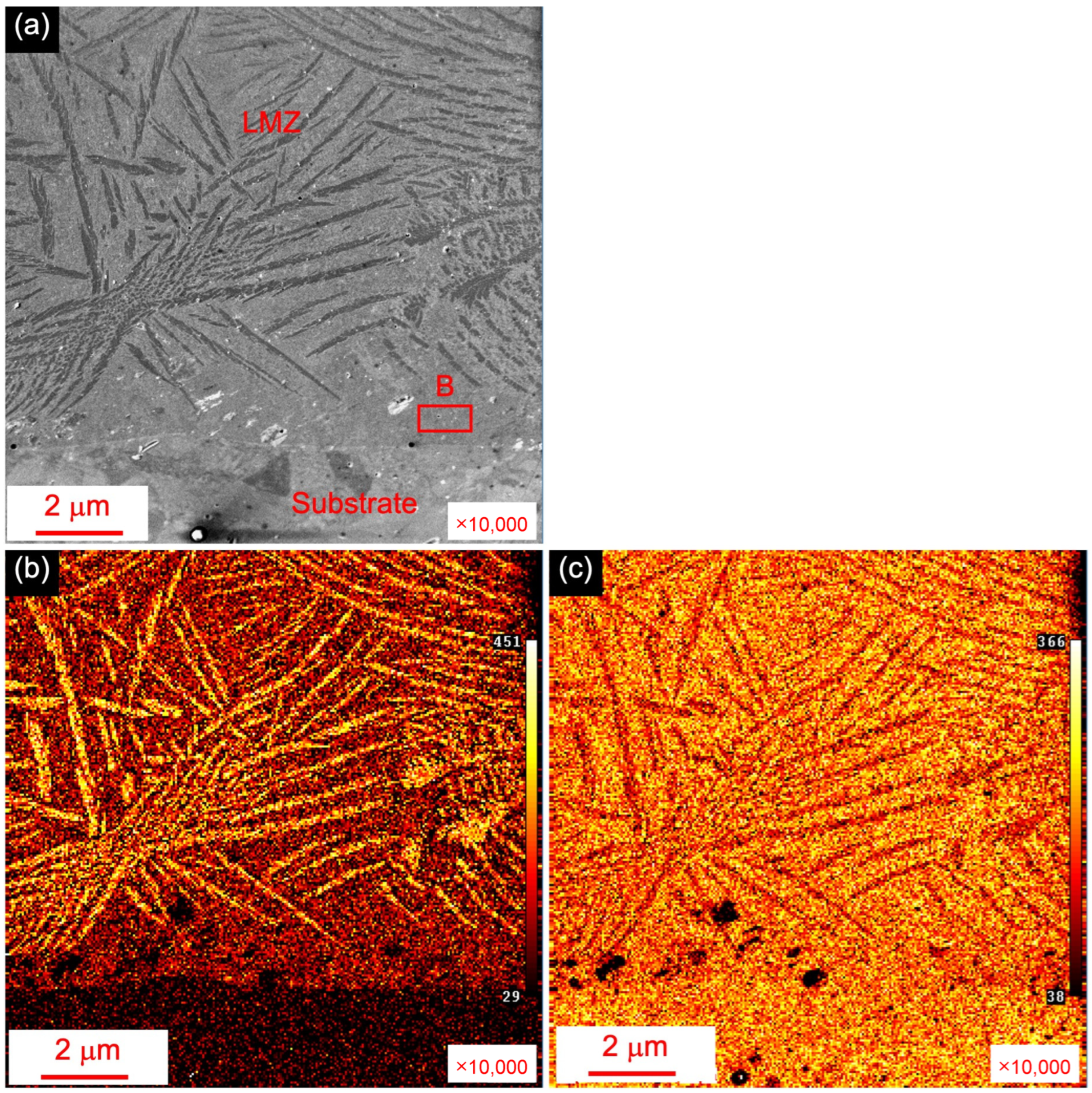
More accurate results, with respect to boron and nitrogen concentration measurements obtained using the AES analysis, are presented in Figure 10 and Figure 11. Figure 10a,b show the distribution of boron at the interface between the LMZ and substrate. Based on the contrast developed at the interface, it is clearly seen that the concentration of boron is evidently higher in the entire cross-section of the LMZ compared with that in the substrate, as shown in Figure 10.
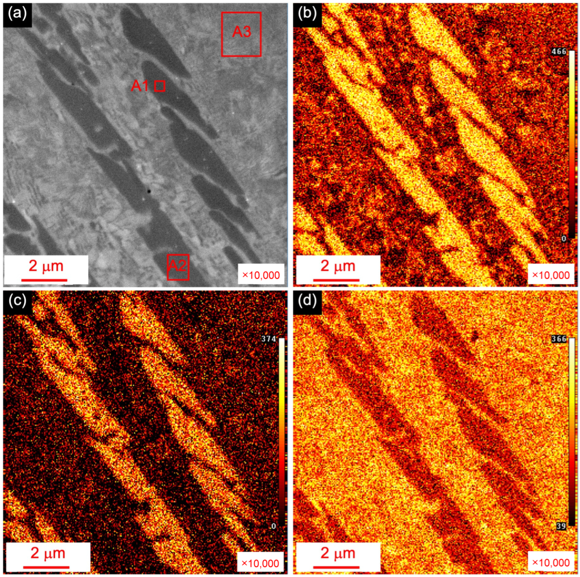
Nevertheless, the largest concentration of boron was detected in the slender chromium–iron-rich eutectic borides, as shown in Figure 11. The chemical composition of certain areas marked in Figure 10a and Figure 11a is presented in Table 3. In general, we can assume from the compositions measured in the corresponding areas that the eutectic is a mixture of the chromium–iron-rich boride and the supersaturated α-iron solid solution. However, given the unrealistically high concentration of boron in the solid solution (see areas B and A3 in Figure 10a and Figure 11a, respectively, and in Table 3), it can reasonably be concluded that a great number density of nanosized precipitates of iron boride could be dispersed in the α-iron solid solution. Hence, to prove this assumption, advanced electron microscopy techniques must be used in the future. Additionally, the latter will allow us to investigate the atomic arrangement of the dislocations whose structure can change under the effect of laser alloying, as was proven in the work by Li et al. [53].
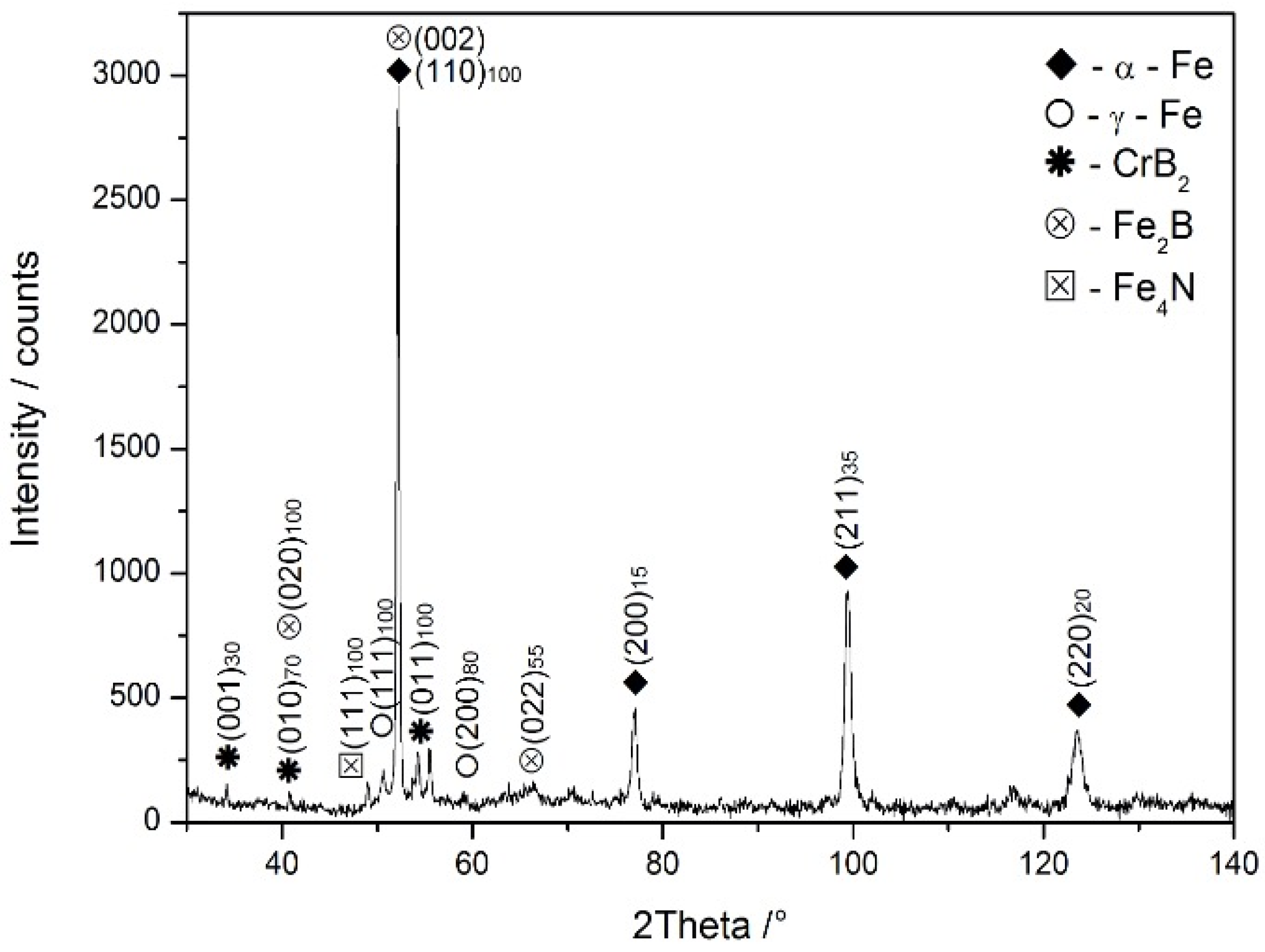
As an example, the phase composition of the 1/400 sample is presented in Figure 12. The results of the XRD analysis confirmed the presence of borides and nitrides in the steel, which is in line with the results of the AES analysis. Borides were detected to be CrB2 (hexagonal lattice) and Fe2B (tetragonal lattice), and the origin of the nitride was found to be Fe4N (cubic lattice, Perovskite type). The presence of α-Fe with bcc lattice and γ-Fe with fcc lattice was also confirmed. However, the amount of the latter was very small, as shown in Figure 12.

3.5. Microhardness Measurements

Table 4 shows that the microhardness of the LMZ in all the studied samples is significantly greater than that for the heat-treated steel substrate. In general, this is primarily attributed to the formation of eutectics based on the very hard borides and nitrides in the microstructure of the LMZ. In relation to the laser scan speed, it should be stressed that an increase in the scan speed led to a significant linear rise of the microhardness of the LMZ, and the trend did not depend on whether the diameter of the laser beam spot was 1 or 1.5 mm (see Table 4). This trend can be explained by an increasing level of solid solution supersaturation achieved owing to the growing scan speed, as assumed above. However, in the case of the 1.5/600 sample, a less evident rise in the microhardness can be explained by the formation of a definite portion of solid solution dendrites to the detriment of the eutectic constituent.
In contrast, the highest hardness was achieved in the case of the 1/600 sample, which can be attributed to a fully eutectic microstructure containing α-iron solid solution supersaturated with boron and nitrogen. Hence, the conditions of the laser treatment, which involve a laser beam spot diameter of 1 mm and a laser scan speed of 600 mm per min, are optimal for the experiment. On the other hand, it should be emphasized that in general, measured values are not high compared with the typical diffusion-boriding process. The same problem has been also mentioned in the work by Kulka et al. [18].
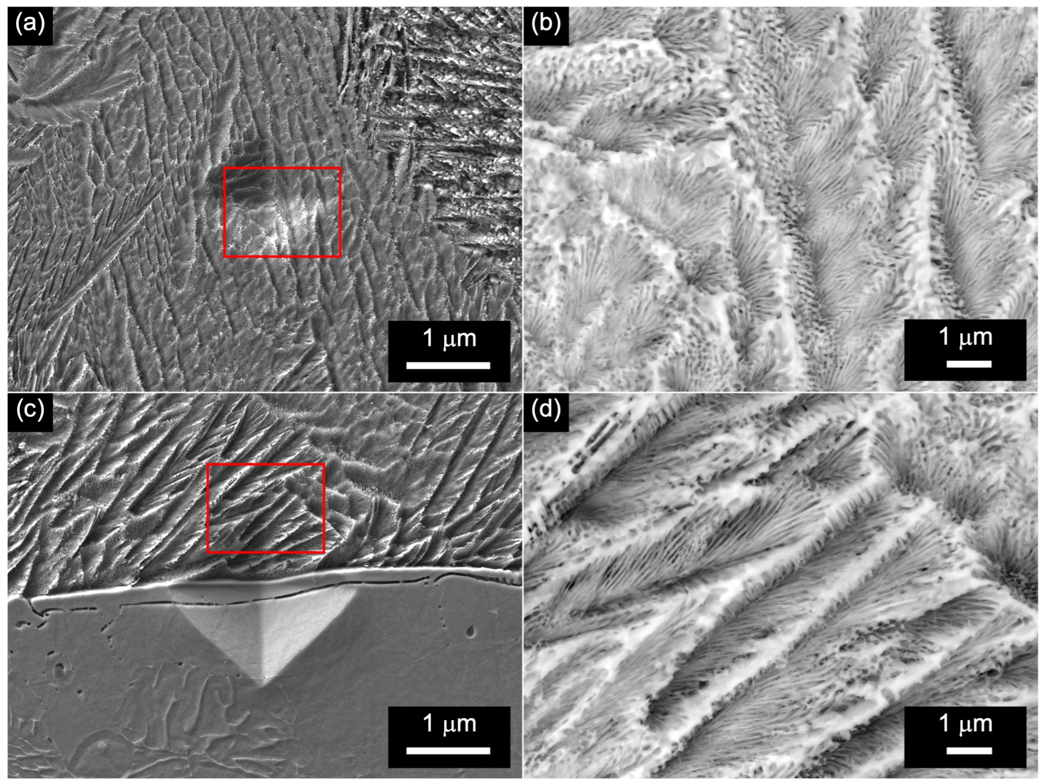
It is well known that the fracture toughness of high-alloyed steel is primarily determined by the hard particles of eutectic carbides, which significantly contribute to the initiation of cracks, for example, in both as-cast [54,55] and wrought [56,57] ledeburitic steel. In some cases, indents may be used to control the excessive brittleness of eutectics. Considering this, the indents left after the microhardness measurements in the areas with the fully eutectic and at the eutectic/substrate interface were carefully examined; some examples are presented in Figure 13.
The corresponding micrographs show that, in all the studied cases, eutectic cracking did not occur, which would prevent brittle fracture of the LMZ during service. On the other hand, an increase in the surface hardness to the values ranging from 545.8.4 ± 12.9 to 804.7 ± 19.4 HV0.1 would dramatically improve the resistance of the steel to wear. The surface hardening of 17-4PH steel can effectively increase the wear resistance of some parts, which are usually manufactured with this steel and used in different engineering applications, for example, pump shafts or gears. There is no doubt that further research is needed to evaluate the wear resistance of additively manufactured 17-4PH stainless steel subjected to laser surface alloying with boron and nitrogen.

4. Conclusions

In the present work, the evolution of the microstructure in the additively manufactured samples of 17-4PH stainless steel subjected to laser surface alloying with amorphous boron and nitrogen at a permanent flow in compressed air to the beam interaction zone using widely varying process parameters was thoroughly studied. The main conclusions drawn are as follows:
  • The final microstructure developed in the LMZ is dependent on a variety of processing parameters that primarily influence the morphology and orientation of eutectic dendrites in the LMZ during laser surface alloying.
  • It was metallographically proven that a fully eutectic microstructure, except for one sample, was developed in the LMZ in the studied samples. According to the AES analysis, the eutectic is formed by chromium–iron-rich boride (containing boron in the range of 27–29 at.%) and the α-iron solid solution supersaturated with boron.
  • In the microstructure of the 1.5/600 sample, alongside eutectics, about 40% of α-iron solid solution dendrites were revealed. It was assumed that under the conditions when the laser power density was lower (due to larger laser beam spot diameter), the highest laser scan speed, i.e., 600 mm/min, could support the formation of the supersaturated α-iron solid solution to the detriment of eutectics.
  • The results of WDS and AES confirmed alloying the LMZ with nitrogen from the air at a permanent flow in compressed air to the beam interaction zone. This finding may be of overriding importance for industrial practice.
  • The formation of the boron eutectic and the supersaturation of the α-iron solid solution with boron and nitrogen (as a part of the eutectic mixture) led to the enhanced microhardness in the LMZ, which was significantly higher compared with that of the heat-treated substrate in the entire range of the used laser spot diameters and laser scan speeds (545.8 ± 12.59–804.7 ± 19.4 vs. 276.8 ± 10.1–312.7 ± 11.7 HV0.1).

Author Contributions

Conceptualization, A.S.C. and O.G.D.; methodology, A.S.C., M.S., Ľ.V. and O.G.D.; investigation, A.S.C., M.S. and Ľ.V.; data curation, M.S., Ľ.V. and I.B.; writing—original draft preparation, A.S.C.; writing—review and editing, A.S.C. and O.G.D. All authors have read and agreed to the published version of the manuscript.

Funding

This research received no external funding.

Data Availability Statement

The raw data supporting the conclusions of this article will be made available by the authors upon request.

Acknowledgments

The authors are grateful to the staff of the MCAE Systems, s.r.o (Kuřim, Czech Republic), Nikolaj Lutsko (Belarusian National Technical University, Belarus), and Martin Kusý for their technical assistance with additive manufacturing, surface laser alloying, and XRD analysis, respectively.

Conflicts of Interest

The authors declare that they have no known competing financial interest or personal relationships that could have appeared to influence the work reported in this paper.

References

  1. Gelin, F.D.; Chaus, A.S. Metallic Materials; Vysheishaya Shkola: Minsk, Belarus, 2007. (In Russian) [Google Scholar]
  2. Douthett, J. Heat Treating of Stainless Steels; Handbook; ASM International: Almere, The Netherlands, 1991; Volume 4, pp. 1681–1757. [Google Scholar]
  3. Riazi, H.; Ashrafizadeh, F.; Hosseini, S.R.; Ghomashchi, R. Influence of simultaneous aging and plasma nitriding on fatigue performance of 17-4 PH stainless steel. Mater. Sci. Eng. A 2017, 703, 262–269. [Google Scholar] [CrossRef]
  4. Bajaj, P.; Hariharan, A.; Kini, A.; Kürnsteiner, P.; Raabe, D.; Jägle, E.A. Steels in additive manufacturing: A review of their microstructure and properties. Mater. Sci. Eng. A 2020, 772, 138633. [Google Scholar] [CrossRef]
  5. Washko, S.D.; Aggen, G. Wrought Stainless Steels; Handbook; ASM International: Almere, The Netherlands, 1990; Volume 1, pp. 1303–1408. [Google Scholar]
  6. Yan, M.F.; Liu, R.L.; Wu, D.L. Improving the mechanical properties of 17-4PH stainless steel by low temperature plasma surface treatment. Mater. Des. 2010, 31, 2270–2273. [Google Scholar] [CrossRef]
  7. Yan, M.F.; Liu, R.L. Influence of process time on microstructure and properties of 17-4PH steel plasma nitrocarburized with rare earths addition at low temperature. Appl. Surf. Sci. 2010, 256, 6065–6071. [Google Scholar] [CrossRef]
  8. Liu, D.; Liu, D.; Zhang, X.; Liu, C.; Ao, N. Surface nanocrystallization of 17-4 precipitation-hardening stainless steel subjected to ultrasonic surface rolling process. Mater. Sci. Eng. A 2018, 726, 69–81. [Google Scholar] [CrossRef]
  9. Zhang, Q.; Hu, Z.; Su, W.; Zhou, H.; Liu, C.; Yang, Y.; Qi, X. Microstructure and surface properties of 17-4PH stainless steel by ultrasonic surface rolling technology. Surf. Coat. Technol. 2017, 321, 64–73. [Google Scholar] [CrossRef]
  10. Giouse, J.-B.; White, K.; Tromas, C. Nanoindentation characterization of the surface mechanical properties of a 17-4PH stainless steel substrate treated with grit blasting and coated with a Cr3C2-NiCr coating. Surf. Coat. Technol. 2019, 368, 119–125. [Google Scholar] [CrossRef]
  11. Deng, D.W.; Zhang, C.P.; Chen, R.; Xia, H.F. Microstructure and microhardness of 17-4PH deposited with Co-based alloy hardfacing coating. Phys. Procedia 2013, 50, 177–184. [Google Scholar] [CrossRef]
  12. Przestacki, D.; Bartkowska, A.; Kukliński, M.; Kieruj, P. The Effects of laser surface modification on the microstructure of 1.4550 stainless steel. MATEC Web Conf. 2018, 237, 02009. [Google Scholar] [CrossRef]
  13. Chen, Z.; Zhou, G.; Chen, Z. Microstructure and hardness investigation of 17-4PH stainless steel by laser quenching. Mater. Sci. Eng. A 2012, 534, 536–541. [Google Scholar] [CrossRef]
  14. Yao, J.; Wang, L.; Zhang, Q.; Kong, F.; Lou, C.; Chen, Z. Surface laser alloying of 17-4PH stainless steel steam turbine blades. Opt. Laser Technol. 2008, 40, 838–843. [Google Scholar] [CrossRef]
  15. Adeyemi, A.A.; Akinlabi, E.T.; Mahamood, R.M.; Sanusi, K.O.; Pityana, S.; Tlotleng, M. Influence of laser power on microstructure of laser metal deposited 17-4 ph stainless steel. IOP Conf. Ser. Mater. Sci. Eng. 2017, 225, 012028. [Google Scholar] [CrossRef]
  16. Kulka, M.; Mikołajczak, D.; Dziarski, P.; Panfil-Pryka, D. Laser surface alloying of austenitic 316L steel with boron and some metallic elements: Properties. Materials 2021, 14, 2987. [Google Scholar] [CrossRef] [PubMed]
  17. Kulka, M.; Mikolajczak, D.; Makuch, N.; Dziarski, P.; Miklaszewski, A. Wear resistance improvement of austenitic 316L steel by laser alloying with boron. Surf. Coat. Technol. 2016, 291, 292–313. [Google Scholar] [CrossRef]
  18. Kulka, M.; Makuch, N.; Pertek, A. Microstructure and properties of laser-borided 41Cr4 steel. Opt. Laser Technol. 2013, 45, 308–318. [Google Scholar] [CrossRef]
  19. Bartkowski, D.; Bartkowska, A.; Popławski, M.; Przestacki, D. Microstructure, microhardness, corrosion and wear resistance of B, Si and B-Si coatings produced on C45 steel using laser processing. Metals 2020, 10, 792. [Google Scholar] [CrossRef]
  20. Bartkowska, A.; Bartkowski, D.; Przestacki, D.; Hajkowski, J.; Miklaszewski, A. Microstructural and mechanical properties of B-Cr coatings formed on 145Cr6 tool steel by laser remelting of diffusion borochromized layer using diode laser. Coatings 2021, 11, 608. [Google Scholar] [CrossRef]
  21. Bartkowska, A.; Jurči, P.; Hudáková, M.; Bartkowski, D.; Kusý, M.; Przestacki, D. The influence of the laser beam fluence on change in microstructure, microhardness and phase composition of FeB-Fe2B surface layer produced on Vanadis-6 steel. Arch. Metall. Mater. 2018, 63, 791–800. [Google Scholar] [CrossRef]
  22. Bartkowska, A.; Bartkowski, D.; Swadźba, R.; Przestacki, D.; Miklaszewski, A. Microstructure, chemical composition, wear, and corrosionresistance of FeB-Fe2B-Fe3B surface layers produced on Vanadis-6 steel using CO2 laser. Int. J. Adv. Manuf. Technol. 2018, 95, 1763–1776. [Google Scholar] [CrossRef]
  23. Kuklinski, M.; Bartkowska, A.; Przestacki, D. Laser alloying monel 400 with amorphous boron to obtain hard coatings. Materials 2019, 12, 3494. [Google Scholar] [CrossRef]
  24. Kuklinski, M.; Bartkowska, A.; Przestacki, D.; Kinal, G. Influence of microstructure and chemical composition on microhardness and wear properties of laser borided Monel 400. Materials 2020, 13, 5757. [Google Scholar] [CrossRef] [PubMed]
  25. Zhang, F.; Stoudt, M.R.; Hammadi, S.; Campbell, C.E.; Lass, E.A.; Williams, M.E. How austenitic is a martensitic steel produced by laser powder bed fusion? A cautionary tale. Metals 2021, 11, 1924. [Google Scholar] [CrossRef]
  26. Eskandari, H.; Lashgari, H.R.; Ye, L.; Eizadjou, M.; Wang, H. Microstructural characterization and mechanical properties of additively manufactured 17–4PH stainless steel. Mater. Today Commun. 2022, 30, 103075. [Google Scholar] [CrossRef]
  27. Shi, Q.; Qin, F.; Li, K.; Liu, X.; Zhou, G. Effect of hot isostatic pressing on the microstructure and mechanical properties of 17-4PH stainless steel parts fabricated by selective laser melting. Mater. Sci. Eng. A 2021, 810, 141035. [Google Scholar] [CrossRef]
  28. Sun, Y.; Hebert, R.J.; Aindow, M. Effect of heat treatments on microstructural evolution of additively manufactured and wrought 17-4PH stainless steel. Mater. Des. 2018, 156, 429–440. [Google Scholar] [CrossRef]
  29. Hu, Z.; Zhu, H.; Zhang, H.; Zeng, X. Experimental investigation on selective laser melting of 17-4PH stainless steel. Opt. Laser Technol. 2017, 87, 17–25. [Google Scholar] [CrossRef]
  30. Gonzalez-Gutierrez, J.; Arbeiter, F.; Schlauf, T.; Kukla, C.; Holzer, C. Tensile properties of sintered 17-4PH stainless steel fabricated by material extrusion additive manufacturing. Mater. Lett. 2019, 248, 165–168. [Google Scholar] [CrossRef]
  31. Yang, K.T.; Kim, M.K.; Kim, D.; Suhr, J. Investigation of laser powder bed fusion manufacturing and post-processing for surface quality of as-built 17-4PH stainless steel. Surf. Coat. Technol. 2021, 422, 127492. [Google Scholar] [CrossRef]
  32. Chemkhi, M.; Marae Djouda, J.; Bouaziz, M.A.; Kauffmann, J.; Hild, F.; Retraint, D. Effects of mechanical post-treatments on additively manufactured 17-4PH stainless steel produced by bound powder extrusion. Procedia CIRP 2021, 104, 957–961. [Google Scholar] [CrossRef]
  33. Bouaziz, M.A.; Marae Djouda, J.; Chemkhi, M.; Rambaudon, M.; Kauffmann, J.; Hild, F. Heat treatment effect of 17-4PH stainless steel manufactured by Atomic Diffusion Additive Manufacturing (ADAM). Procedia CIRP 2021, 104, 935–938. [Google Scholar] [CrossRef]
  34. Emminghaus, N.; Hoff, C.; Hermsdorf, J.; Kaierle, S. Residual oxygen content and powder recycling: Effects on surface roughness and porosity of additively manufactured Ti-6Al-4V. Addit. Manuf. 2021, 46, 102093. [Google Scholar] [CrossRef]
  35. Chaus, A.S.; Devoino, O.G.; Sahul, M.; Vančo, Ľ.; Buranský, I.; Kusý, M. Effect of surface roughness on laser surface alloying of additively manufactured 17-4PH stainless steel. Surf. Coat. Technol. 2023, 454, 129161. [Google Scholar] [CrossRef]
  36. Siddiqui, A.A.; Dubey, A.K. Optimization of geometrical and mechanical characteristics in laser surface alloying. Mater. Today Proc. 2021, 44, 1108–1110. [Google Scholar] [CrossRef]
  37. Saltykov, S.A. Stereometric Metallography; Metallurgiya: Moscow, Russia, 1970. [Google Scholar]
  38. Derimow, N.; Schwalbach, E.J.; Benzing, J.T.; Killgore, J.P.; Artusio-Glimpsec, A.B.; Hrabe, N.; Simonds, B.J. In situ absorption synchrotron measurements, predictive modeling, microstructural analysis, and scanning probe measurements of laser melted Ti-6Al-4V single tracks for additive manufacturing applications. J. Alloys Compd. 2022, 900, 163494. [Google Scholar] [CrossRef]
  39. Higashi, M.; Ozaki, T.; Moronaga, T.; Hara, T.; Osada, T.; Kawagishi, K. Microstructural characteristics of laser surface melted MoSiBTiC alloy. Mater. Lett. 2020, 278, 128465. [Google Scholar] [CrossRef]
  40. Devojno, O.G.; Feldshtein, E.; Kardapolava, M.A.; Lutsko, N.I. On the formation features; structure, microhardness and tribological behavior of single tracks and coating layers formed by laser cladding of Al- Fe powder bronze. Surf. Coat. Technol. 2019, 358, 195–206. [Google Scholar] [CrossRef]
  41. Chaus, A.S.; Maksimenko, A.V.; Fedosenko, N.N.; Ćaplovič, Ľ.; Myshkovets, V.N. Formation of structure of a high-speed steel upon laser surface melting. Phys. Met. Metallogr. 2019, 120, 269–277. [Google Scholar] [CrossRef]
  42. Chaurasia, J.K.; Jinoop, A.N.; Parthasarathy, P.; Paul, C.P.; Bindra, K.S.; Bontha, S. Study of melt pool geometry and solidi cation microstructure during laser surface melting of Inconel 625 alloy. Optik 2021, 246, 167766. [Google Scholar] [CrossRef]
  43. Leech, P.W. Laser surface melting of a complex high alloy steel. Mater. Des. 2014, 54, 539–543. [Google Scholar] [CrossRef]
  44. Chaus, A.S.; Maksimenko, A.V.; Fedosenko, N.N.; Ćaplovič, Ľ.; Myshkovets, V.N. Formation of structure of an annealed high-speed steel upon laser surface melting. Phys. Met. Metallogr. 2019, 120, 371–377. [Google Scholar] [CrossRef]
  45. Krakhmalev, P.; Yadroitsev, I. Microstructure and properties of intermetallic composite coatings fabricated by selective laser melting of TieSiC powder mixtures. Intermetallics 2014, 46, 147–155. [Google Scholar] [CrossRef]
  46. Sun, G.; Zhou, R.; Li, P.; Feng, A.; Zhang, Y. Laser surface alloying of C-B-W-Cr powders on nodular cast iron rolls. Surf. Coat. Technol. 2011, 205, 2747–2754. [Google Scholar] [CrossRef]
  47. Monisha, K.; Shariff, S.M.; Sekar, A.; Raju, R.; Manonmani, J.; Senthilselvan, J. Titanium boride coating by high power diode laser alloying of amorphous boron with titanium and its surface property investigations. Opt. Laser Technol. 2024, 170, 110159. [Google Scholar] [CrossRef]
  48. Zhou, R.; Sun, G. Laser alloying with Mn + Cr3C2 and Mn + NiCr-C for improved wear and corrosion resistance of stainless steel. Surf. Coat. Technol. 2022, 451, 129076. [Google Scholar] [CrossRef]
  49. Aveson, J.; Reinhart, G.; Goddard, C.; Nguyen-Thi, H.; Mangelinck-Noėl, N.; Tandjaoui, A.; Davenport, J.; Warnken, N.; Di Gioacchino, F.; Laord, T. On the deformation of dendrites during directional solidification of a nickel-based superalloy. Metall. Mater. Trans. A 2019, 50, 5234–5241. [Google Scholar] [CrossRef]
  50. Labunets, V.F. Laser treatment of rubbing surfaces of machine parts and tools. Bull. Kyiv Int. Univ. Civ. Aviat. 1998, 1, 72–76. (In Russian) [Google Scholar]
  51. Chaus, A.S.; Pokorný, P.; Čaplovič, Ľ.; Sitkevich, M.V.; Peterka, J. Complex fine-scale diffusion coating formed at low temperature on high-speed steel substrate. Appl. Surf. Sci. 2018, 437, 257–270. [Google Scholar] [CrossRef]
  52. Chaus, A.S.; Sitkevich, M.V.; Pokorný, P.; Sahul, M.; Haršáni, M.; Babincová, P. Wear resistance and cutting performance of high-speed steel ball nose end mills related to the initial state of tool surface. Wear 2021, 472–473, 203711. [Google Scholar] [CrossRef]
  53. Li, J.; Chen, B.; Wang, M.; Jing, C.; Fan, Z.; Zhang, Z.; Li, Y.; Zhang, C. Microstructure performance and nano-effect of laser alloying composites with multi-phase on TA1 titanium alloy. Opt. Laser Technol. 2024, 169, 109975. [Google Scholar] [CrossRef]
  54. Chaus, A.S.; Sahul, M.; Moravčík, R.; Sobota, R. Role of microstructural factor in wear resistance and cutting performance of high-speed steel end mills. Wear 2021, 474–475, 203865. [Google Scholar] [CrossRef]
  55. Chaus, A.S. Microstructural and properties evaluation of M2 high speed steel after inoculating addition of powder W and WC. Mater. Sci. Technol. 2014, 30, 1105–1115. [Google Scholar] [CrossRef]
  56. Chaus, A.S.; Rudnitskii, F.I.; Murgas, M. Structural inheritance and special features of fracture of high-speed steels. Met. Sci. Heat Treat. 1997, 39, 53–56. [Google Scholar] [CrossRef]
  57. Chaus, A.S. Application of bismuth for solidification structure refinement and properties enhancement in as–cast high–speed steels. ISIJ Int. 2005, 45, 1297–1306. [Google Scholar] [CrossRef]
Figure 1. Flowchart of the methodology applied in this study.
Crystals 14 00569 g001
Figure 2. (a) Overall microstructure of the LAZ in the 1/200 sample and (b) the microstructure of the steel substrate: F—ferrite and M—martensite.
Crystals 14 00569 g002
Figure 3. (a) Overall microstructure of the LMZ and its microstructure in (b) the upper, (c) middle, and (d) bottom regions in the 1/200 sample.
Crystals 14 00569 g003
Figure 4. (a) Overall microstructure of the LMZ and its microstructure in (b,c) the upper and (d) bottom regions in the 1/400 sample. (c) Detailed fragments of the microstructure are pointed out by a rectangle in (b). Adapted from [35].
Crystals 14 00569 g004
Figure 5. (a) Overall microstructure of the LMZ and its microstructure in (b) the upper and (c,d) bottom regions in the 1/600 sample. (d) Detailed fragments of the microstructure are pointed out by a rectangle in (c).
Crystals 14 00569 g005
Figure 6. (a) Overall microstructure of the LMZ and its microstructure in (b) the upper, (c) middle, and (d) bottom regions in the 1.5/200 sample.
Crystals 14 00569 g006
Figure 7. (a) Overall microstructure of the LMZ and its microstructure in (b) the upper, (c) middle, and (d) bottom regions in the 1.5C/400 sample.
Crystals 14 00569 g007
Figure 8. (a) Overall microstructure of the LMZ and its microstructure in (bd) the middle and (e,f) bottom regions in the 1.5/600 sample. (b,c) Detailed fragments of the microstructure are pointed out by rectangles 1 and 2 and in (a), respectively.
Crystals 14 00569 g008
Figure 9. (a) SE SEM image showing the microstructure and WDS line scans of (b) boron, (c) nitrogen, and (d) iron in the LMZ in the 1.5/400 sample.
Crystals 14 00569 g009
Figure 10. (a) SE SEM image showing the microstructure at the interface between the LMZ and substrate in the 1.5/400 sample and AES elemental maps of (b) boron and (c) iron in the area shown in (a).
Crystals 14 00569 g010
Figure 11. (a) SE SEM image showing the microstructure of eutectics in the LMZ in the 1.5/400 sample and AES elemental maps of (b) boron, (c) chromium, and (d) iron in the areas shown in (a).
Crystals 14 00569 g011
Figure 12. XRD pattern of the LMZ in the 1/400 sample.
Crystals 14 00569 g012
Figure 13. Indents left after the microhardness measurements in (a,b) eutectic and (c,d) at the eutectic/substrate interface. (b,d) Detailed fragments of the areas pointed out by rectangles in (a,c), respectively.
Crystals 14 00569 g013
Table 1. The average maximum thickness of the LMZ in the studied samples, μm.
Sample1/2001/4001/6001.5/2001.5/4001.5/600
Thickness262 ± 19.8199 ± 16.5176 ± 16.0242 ± 19.2184 ± 14.7160 ± 12.2
Table 2. Volume fraction (VF) of the eutectic in the studied samples, %.
Sample1/2001/4001/6001.5/2001.5/4001.5/600
VF100 ± 0.0100 ± 0.0100 ± 0.0100 ± 0.0100 ± 0.060 ± 4.2
Table 3. Content of elements in certain areas of the LMZ in the 1.5/400 sample, at.%.
PositionBNCrFeNi
Area B, see Figure 1013.95.413.164.33.3
Area A1, see Figure 1127.08.023.740.11.2
Area A2, see Figure 1128.97.423.838.31.1
Area A3, see Figure 1111.59.211.364.63.4
Table 4. Microhardness (HV0.1) of the steel in the LMZ (numerator) and substrate (denominator) of the studied samples.
Sample1/2001/4001/600
HV0.1554.4 ± 13.1/279.0 ± 9.9636.7 ± 18.5/276.8 ± 10.1804.7 ± 19.4/281.8 ± 10.2
Sample1.5/2001.5/4001.5/600
HV0.1545.8 ± 12.9/302.8 ± 10.0655.0 ± 17.5/291.3 ± 10.5781.5 ± 18.8/312.7 ± 11.7
Disclaimer/Publisher’s Note: The statements, opinions and data contained in all publications are solely those of the individual author(s) and contributor(s) and not of MDPI and/or the editor(s). MDPI and/or the editor(s) disclaim responsibility for any injury to people or property resulting from any ideas, methods, instructions or products referred to in the content.