Article

Printing Direction Effects on the Sliding Contact Response of a Binder Jetting 3D-Printed WC-Co Hardmetal

by
Laura Cabezas
1,2,*,
Christian Berger
3,
Emilio Jiménez-Piqué
1,2,
Johannes Pötschke
3 and
Luis Llanes
1,2,*
1
CIEFMA, Department of Materials Science and Engineering, Universitat Politècnica de Catalunya—BarcelonaTech, Campus Diagonal Besòs-EEBE, 08019 Barcelona, Spain
2
Barcelona Research Center in Multiscale Science and Engineering, Universitat Politècnica de Catalunya—BarcelonaTech, Campus Diagonal Besòs, 08019 Barcelona, Spain
3
Fraunhofer Institute for Ceramic Technologies and Systems IKTS, 01277 Dresden, Germany
*
Authors to whom correspondence should be addressed.
Crystals 2024, 14(6), 573; https://doi.org/10.3390/cryst14060573
Submission received: 15 May 2024 / Revised: 7 June 2024 / Accepted: 17 June 2024 / Published: 20 June 2024
(This article belongs to the Special Issue Advances in New Multifunctional Hard Materials)

Abstract

:
Binder jetting additive manufacturing offers a promising route to produce complex geometries in cemented carbides (WC-Co), but it may introduce direction-dependent microstructural variations potentially affecting wear resistance. This study investigates the influence of printing direction on the sliding contact response of 3D-printed and subsequently sintered (BJT) WC-12%Co. Prismatic specimens were printed along two orientations and subjected to single and repetitive scratch tests on three orthogonal faces. The microstructure, Vickers and scratch hardness, and wear rate were analyzed. The results showed a heterogeneous microstructure consisting of a matrix of fine carbides where several large particles where embedded. It was different from the homogenous microstructural scenarios exhibited by conventionally pressed and sintered fine- and coarse-grained hardmetals, used as reference for comparison purposes. The influence of printing direction on either the microstructure or mechanical properties of BJT specimens was found to be negligible. Interestingly, BJT samples exhibited superior wear resistance than the reference hardmetals, even though the hardness levels were alike for all the studied hardmetal grades. Such behavior is attributed to the co-existence of coarse and fine carbides within the microstructure, combining the energy absorption capability of the former with the inherent strength of the latter. These findings, together with the intrinsic flexibility and versatility advantages associated with additive manufacturing, highlight the potential of BJT hardmetals to be used in applications where contact load bearing or wear resistance are critical design parameters. Finally, the effectiveness of implementing an iterative sliding contact test for evaluating wear behavior in cemented carbides was also validated.

1. Introduction

WC-Co cemented carbides, in a practice commonly referred to as hardmetals, are the first material choices for a wide range of extremely demanding applications, such as metal cutting/forming tools, mining bits, and wear-resistant components. The main reason behind that is the outstanding combination of hardness, toughness, and abrasion resistance that they exhibit [1,2]. In general, hardmetal tools and components are manufactured by conventional powder metallurgy (PM) routes, i.e., pressing and/or extrusion followed by sintering. However, due to more demanding applications in industry for hardmetal products, there is a need to consolidate them in complex geometries. Within this context, the additive manufacturing (AM) of cemented carbides emerges as a natural option. It not only allows for the fabrication of intricated shapes that cannot be produced with traditional PM but also permits a reduction in the manufacturing lead time, as well as minimizing the post-processing steps and tooling operations [3,4,5,6,7].
AM is, by definition, a process where objects are produced by depositing a combination of material layers until the desired 3D model is achieved [8]. AM techniques may be classified in different categories, depending on the binding mechanism and the feedstock morphology or delivery. From the perspective of binding mechanisms, they can be divided in energy-delivery or melt-based techniques and material-delivery or sinter-based ones. Although extensive research has been conducted—since the early 1990s—on the processing of hardmetals involving several melt-based AM routes (for a detailed review, see Ref. [6]), these have not been successful in terms of matching the microstructure, properties, and functionality found in hardmetal grades consolidated following conventional press and sintering. Accordingly, no energy-delivery route has turned into commercial reality for processing hardmetals by means of AM. Primary causes for it are linked to the intrinsic challenges associated with the metal–ceramic composite nature of these materials, as critically discussed in Slobodyan and coworkers’ review paper [6]. On the other hand, as sinter-based routes are implemented following sequential and separated stages of geometrical shape formation and final consolidation by sintering, they are usually capable of achieving homogeneous two-phase microstructures; thus, it is aimed for the properties to be linked to the proper processing and compositions of hardmetals. Within this framework, two material delivery routes—binder jetting (BJT) [9,10,11,12,13,14,15] and material extrusion [16,17,18,19,20,21]—have emerged as the leading technologies for fabricating hardmetal parts. However, different from the latter, the former is the only one that has currently achieved maturity to fabricate hardmetal parts on a mass scale [7]. Furthermore, BJT has reached the highest level of technology readiness of all sinter-based techniques and has already been used to fabricate cemented carbide parts that are both large and small, as well as with a high degree of shape complexity. For this reason, BJT is the AM route invoked and investigated in this work.
Independent of the sinter-based AM route taken to process the final sample, it is known that modifying different parameters during the printing or sintering processes may have an effect on the final outcome [9,22,23,24]. Within this context, printing direction may be pointed out as a parameter that could affect the performance of AMed hardmetals. This is particularly relevant for samples with geometries whose dimensions are different in distinct axis; thus, their placement on the printing bed and layer growth direction become two variables to take into consideration. To the best of the authors’ knowledge, the influence of printing direction effects on the microstructure, properties, and performance of hardmetals has not been previously addressed in the open literature; hence, it will be the main testing variable recalled and evaluated in this study.
Regarding the implementation of hardmetals, it is common that tools and components made of these materials are used under service conditions that involve abrasive wear. In these applications, there exists a direct contact of the material surface with the counterpart, this being either cut/formed metallic alloys, mined ores, and drilled hard rocks, among others. The wear resistance of hardmetals is commonly studied using standard tribotest systems, where the abrasive material is rubbed against the studied samples under a specific flow rate, creating wear patterns similar to those produced in actual worn tools and components [25,26]. Meanwhile, comprehensive information on the wear behavior of these materials has been gathered by combining forensic reports of WC–Co components used in a wide range of applications with laboratory-based testing and modeling efforts, as detailed in some review-like contributions in the literature [27,28,29,30]. One relevant outcome of such an interdisciplinary approach is the proposal and validation of the scratch—both single-pass and repetitive—test as a model system for the abrasion of hardmetals. Such a sliding contact test, broadly used to evaluate the adhesion strength of coatings to substrates [31,32], consists of applying a specific load into the surface material using a tip, typically a diamond indenter, and sliding it over the sample under a known speed and distance. Furthermore, it is usually complemented by in situ and post-failure inspection of the failure mode evolution and involved mechanisms as a function of the applied load. Accordingly, scratch testing has proven to be extremely useful for understanding the tribomechanical response of both hard coating/substrate systems (e.g., Refs. [32,33,34]) as well as hard and brittle materials, such as ceramics and hardmetals (e.g., Refs. [35,36,37,38,39]), when subjected to sliding contact conditions. Following the above ideas, the iterative scratch test is implemented in this work to evaluate the printing orientation effects on the sliding contact response of WC-Co samples manufactured by BJT. Single- and multiple-pass scratch testing is complemented with a systematic and detailed characterization of the evolution of microstructural scenario changes and damage mechanisms by means of field emission scanning electron microscopy.

2. Materials and Methods

2.1. Materials

Prismatic specimens of 15 mm × 10 mm × 7.5 mm dimensions were printed using a spray-dried and pre-sintered WC-12%wt.Co granulate in combination of an organic binder without growth inhibitors developed by Fraunhofer IKTS. In doing so, a ZPrinter Z510 from former ZCorporation (now 3D-Systems) was employed. In all the cases, printing fluid saturation was set to 150 % and 200% at the core and the shell parts, respectively. The layer thickness was kept constant at 100 µm. The employed binder was VisiJet PXL. A curing step was applied before the debinding stage for 1h at 40 °C in order to reduce the water content. Debinding and sintering were performed by using a SinterHIP furnace from FCT Systeme. Green compacts were sintered in a vacuum up to 1500 °C, and an argon pressure of 100 bar was applied. The final dimensions of the samples 3D-printed, followed by sinterHIP (from now on simply referred to as BJT), were 10.4 mm × 6.9 mm × 5.2 mm, corresponding to a shrinkage of 30% with respect to those of the green specimen. In the BJT of hardmetals, green densities below 50% are very likely. This is related to the fact that hardmetal powders, different from those of pure metals or alloys, cannot be gas-atomized. It hinders the possibility of attaining relatively high green density values because, ideally, round and dense particles cannot be produced. In general, flowable hardmetal granules for BJT are produced using spray granulation; here, the resulting residual porosity in such granules could be reduced by higher sintering temperature and time. However, this is associated with a reduction in free surfaces, which leads to a loss of sintering activity before the actual sintering starts. Within the above context, due to the low green densities of less than 40% theoretical density, a relatively high sintering temperature (1500 °C), as compared to those used for consolidating green samples following more conventional shaping methods, was needed for achieving complete densification. However, it resulted in a heterogeneous microstructure, with a significant volume fraction of carbides larger than 3 microns, as has been detailed in a previous work by the authors [40]. Density and magnetic properties were measured according to ISO 3369 and 3326 [41,42]. In addition to full density, a two-phase microstructure of WC and Co was achieved, without any undesired eta phase or free carbon.
Aiming to study the printing direction effects, two prismatic samples were printed with their longest sides along different axis: z (S1) and y (S2) (Figure 1), and they are here referred to as vertically and horizontally printed.
Microstructural characterization was conducted in three out of the six faces of each sample: A, B, and C corresponding to x–y, y–z, and x–z planes, respectively. In doing so, the sintered samples were first mounted in Bakelite and then ground and diamond polished up to mirror-like surface finish following a 6, 3, and 1 μm sequence. The mean carbide grain size was determined by image analysis of micrographs acquired using a Zeiss Neon40 field emission scanning electron microscopy (FESEM, Zeiss, Jena, Germany), whereas metallic binder content values were based on the initial binder content used during powder manufacturing and verified by X-ray Fluorescence (XRF) spectrometry. In order to reduce grain size uncertainty, at least 400 grains were measured for each investigated face and specimen.

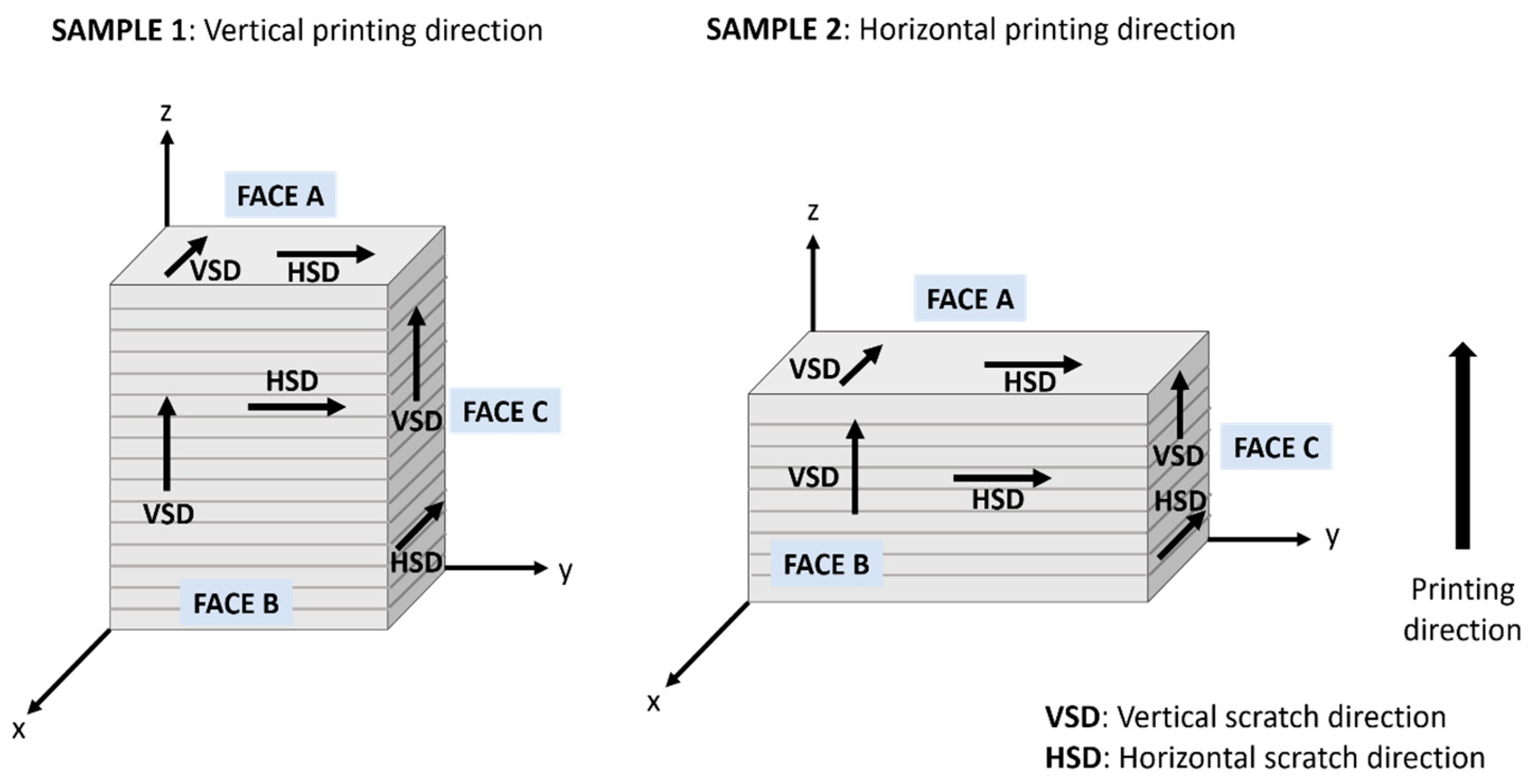
2.2. Iterative Scratch Tests and Deformation/Damage Mechanisms

Scratch tests were carried out using a sliding contact unit (CSM Revetest) equipped with a force and depth sensor. A conical diamond Rockwell C indenter, with a 200 µm tip radius, was used in all tests. Based on the literature data [38] and the findings reported in a previous work [40], 30 N was chosen as a suitable value for conducting the scratch tests under a constant load for the BJT samples. A scratch length of 3 mm at a linear displacement of 3 mm/min was applied. Three different types of tests were performed: single, five, and ten passes. The idea of conducting iterative tests was to evaluate the induced wear behavior, under sliding contact, in BJT samples as well as to assess the influence of a heterogeneous fine/coarse microstructure, as compared to homogeneous ones, on the tribological response of hardmetals. All types of tests were performed in the three faces of each sample and in two different directions: vertical and horizontal, corresponding to scratches being performed parallel and perpendicular, respectively, to the printing direction. The schematic details of the scratch tests performed are included in Figure 1.
Attempting to relate the sliding contact response with the microstructure, residual grooves, as well as linked deformation and damage mechanisms, induced by the iterative scratches were systematically and extensively examined by FESEM at different length scales. Particular attention was paid to evaluate possible formation and development of a “tribo-layer”, as reported for these materials in the literature (e.g., Refs [35,38]).

3. Results and Discussion

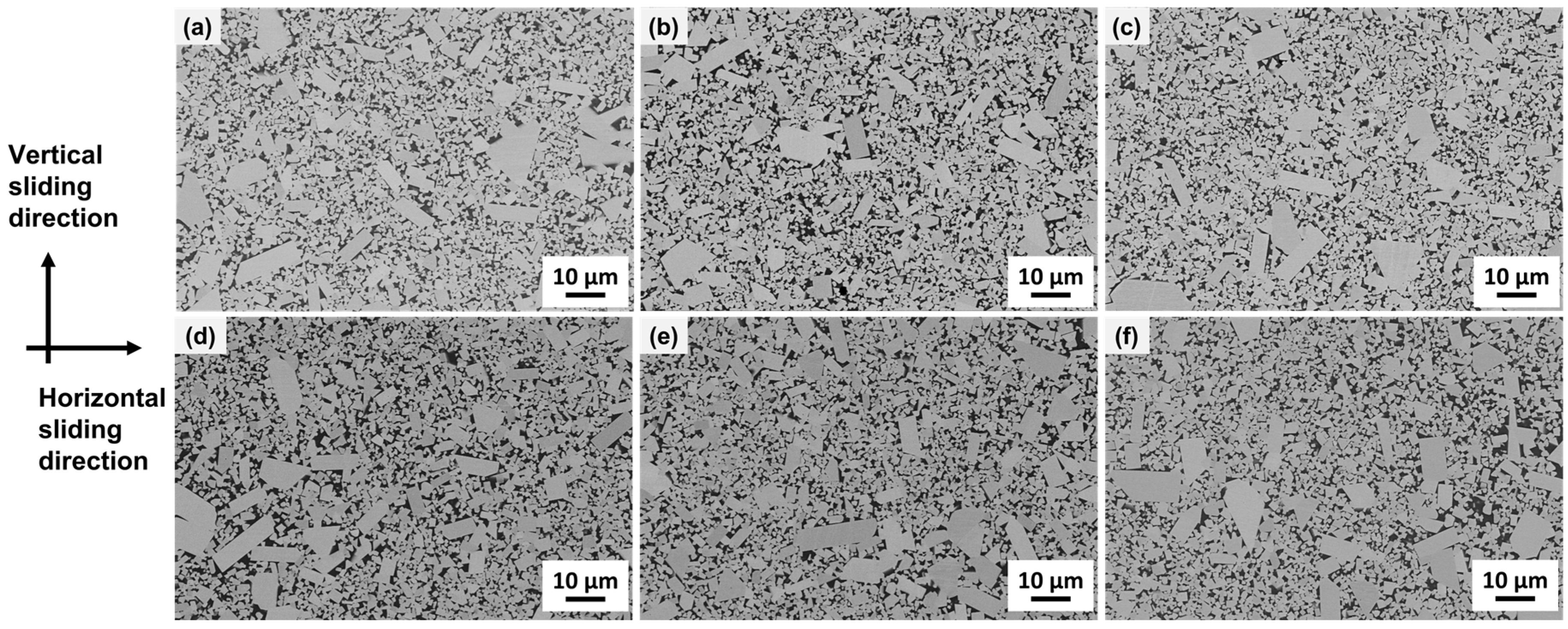
3.1. Microstructural Characteristics

As can be seen in Figure 2, and similar to the findings previously reported by the authors of this work [40], the microstructural scenario may be described as isotropic for both specimens S1 and S2. However, the microstructure is not homogeneous in any case, as the abnormal growth of several carbide grains is evidenced in all faces for both samples under consideration.
Within this context, the heterogeneous microstructure of the BJTed hardmetal studied may be described (Table 1) as consisting of one large population (about 80% in volume) of fine grains (<3 μm) acting as a matrix, where several coarse carbides (>3 μm) are somehow embedded. Taking this into consideration, for comparison purposes, two reference hardmetal grades with homogeneous microstructures—fine-grained WC-11%wt.Co (11F) and coarse-grained WC-7%wt.Co (7C)—which were both consolidated following a conventional pressing and sintering route, were also assessed and documented in this investigation. The binder content selected for defining these reference grades was based on the requirement of them having similar hardness values to those determined for the BJT hardmetal studied (Table 1), i.e., values of Vickers hardness measured under an applied load of 10 Kgf (HV10) between 11 and 12 GPa.

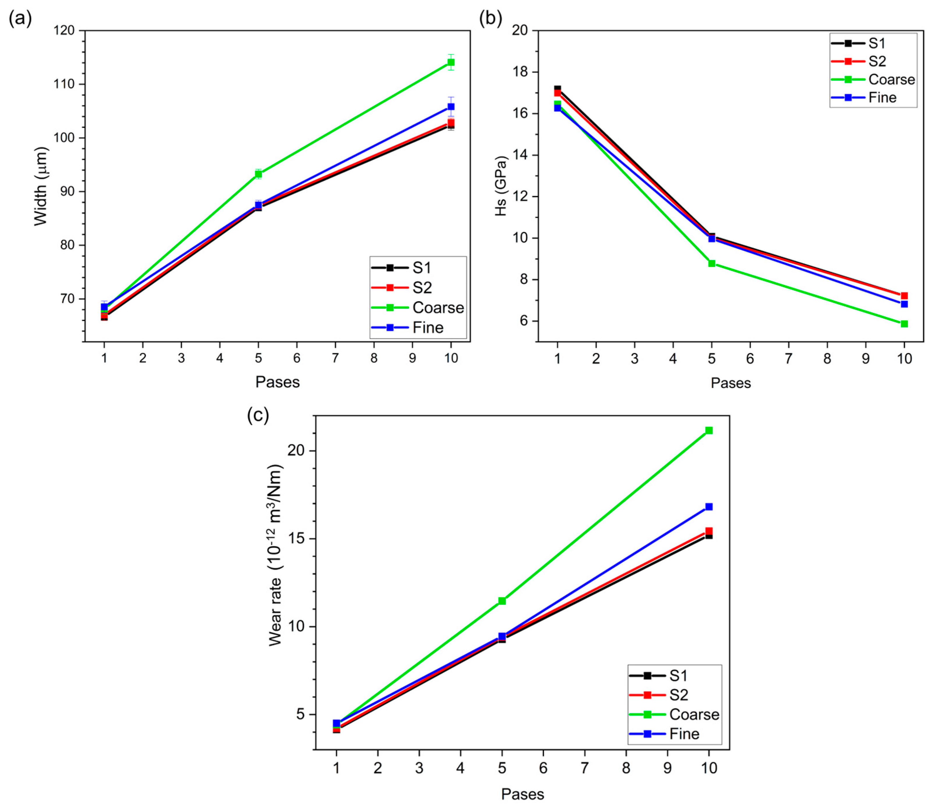
3.2. Scratch Test Performance

Figure 3 shows the evolution of the scratch groove width as a function of the number of passes for all the analyzed faces and test directions, for Samples S1 (Figure 3a) and S2 (Figure 3b). As it could be expected, from the findings reported above for the microstructure and hardness, the scratch wear performance follows a similar isotropic nature trend.
Since both of the printed samples present alike behavior, the same face and scratch test direction for both the S1 and S2 samples were taken in order to assess the printing orientation’s influence on the iterative scratch response, as well as to compare them with the ones found in the reference grades. Figure 4 shows the evolution of the scratch groove width, scratch hardness, and wear rate as a function of the number of passes. In doing so, the scratch hardness (Hs) was calculated as follows [43]:
H s = 8 P π w 2
where P is the scratch applied load (30 N) and w is the scratch groove width; the wear rate may be expressed as follows [38,44]:
W e a r R a t e = V / P S
where V is the net volume removed, estimated assuming a semi-circular cross-section on the basis of the sphero-conical geometry of the indentation tip used [40], and s is the sliding distance.
Several observations may be highlighted. First, the iterative scratch response for both the S1 and S2 specimens is quite similar, i.e., the printing direction effects could be disregarded. Meanwhile, direct comparison with the behavior exhibited by the grades shaped by means of conventional pressing and sintering and with homogeneous microstructures indicates that the sliding contact response of the printed samples is quite close to the one assessed for the fine-grained reference material, i.e., more wear-resistant than the reference coarse one. Although it may be rationalized on the basis of the much higher fraction of fine carbides within the heterogeneous microstructure assemblage of S1 and S2 specimens, it is indeed interesting because all the grades under comparison have similar hardness values. Second, the sliding contact response is relatively similar after one one-pass scratch test for all the materials studied, but it starts to be different for the reference coarse grade compared to the others as multiple scratches are performed. Considering that the hardness values are similar for all of them, such lower wear resistance of the coarse grade exhibited as early as after five-pass scratches should be linked to damage micromechanisms intrinsic to the relatively larger carbides, as will be discussed later. Finally, after ten-pass scratch tests, the sliding contact response of the reference grades is not only significantly lower for coarse-grained hardmetal but it also starts to be distinct for the fine-grained one compared to the behavior determined for the BJT samples. This is in agreement with the results reported in the literature for other BJT hardmetals with similar heterogeneous microstructures [45], and it would point out that—for a given hardness level—the wear resistance of hardmetals is enhanced as a consequence of the bimodal-like assemblage exhibited by the printed specimens.

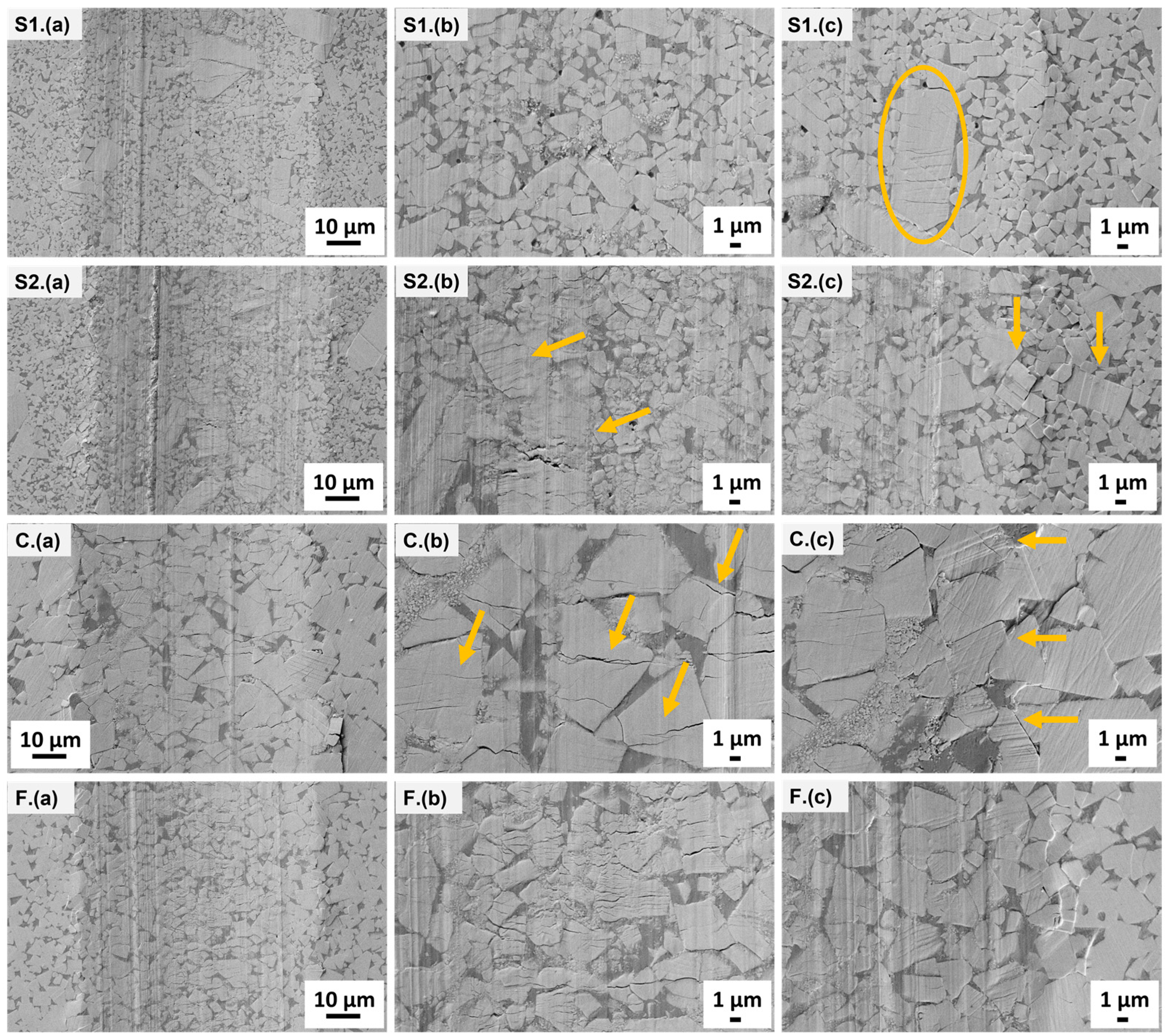
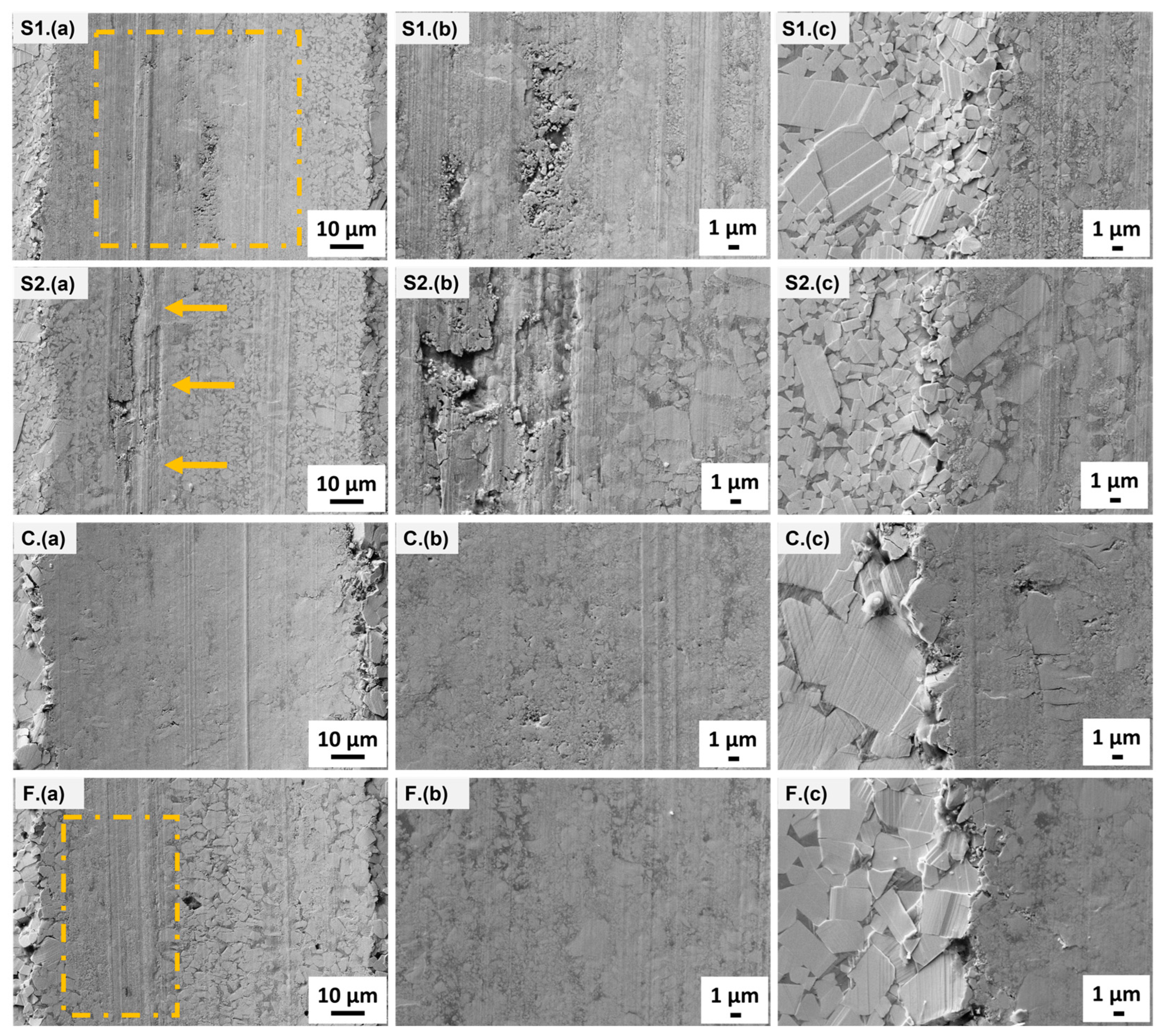
3.3. Wear Mechanisms Induced by Means of Iterative Scratches

Scratch grooves after one, five, and ten passes were inspected by FESEM. They are sequentially shown in terms of low-magnification (groove) and high-magnification (center and edge) micrographs of the resulting scratch tracks in Figure 5, Figure 6, and Figure 7, respectively. As before, considering the isotropic and uniform behavior—regarding face and scratch test direction—assessed for the printed specimens, a systematic and detailed examination for these materials was carried out in grooves resulting from scratches conducted in the Face B vertical direction exclusively.
For BJT specimens, as expected, the emergence and evolution of the irreversible changes observed are identical. After one pass, slip lines and cracking in large carbides are the unique damage features (Figure 5 (S1, S2)). However, with repetitive scratches, coarse WC particles become shattered, and resulting small fragments are either redeposited or re-embedded into the metallic binder within regions adjacent to the large carbides (Figure 6 (S1, S2)).
The above-described damage emergence and evolution is closer to the one observed for the reference coarse-grained hardmetal (Figure 5 (C) and Figure 6 (C)), but in the latter, it is more homogeneously distributed along the center region of the scratch track. One direct consequence is the fact that BJT specimens require 10 passes to develop a defined tribo-layer, similar to the case of the reference fine-grained material (Figure 7 (S1, S2, F)). Regarding the latter, the referred tribo-layer is also achieved after 10 iterative scratches, although here it is preceded by delayed but more severe cracking of the finer WC particles (Figure 6 (F) and Figure 7 (F)). In the literature, it is reported that carbides with sizes lower than 4 µm exhibit less slip capability, promoting and then cracking or plucking-out the affected WC particles [29].
The plastic deformation features within carbides are more noticeable in the edges of the track, where pile-ups of material emerge for all the studied samples (Figure 5, Figure 6, and Figure 7, images c corresponding to the edge of the groove). In the coarse-grained grade as well as in areas surrounding large carbides for BJT samples, metallic binder extrusion where some carbide debris are relodged may be evidenced at the edges.
In general, and following all the above findings, it may be concluded that relatively higher wear resistance exhibited by BJT specimens, particularly noted after 10 sliding contact passes, should result from the beneficial synergy between the high plastic deformation capability of large carbides surrounded by relatively thicker binder regions and the intrinsic strength of the large fraction of fine carbides acting as a matrix within the microstructural assemblage of these materials.

4. Conclusions

This study aimed to assess the influence of printing direction on the sliding contact response of a WC-Co cemented carbide grade produced via binder jetting 3D printing. This sinter-based route has emerged as the most promising option to fabricate hardmetal parts on a mass scale, particularly because extensive research conducted on aspects related to processing for these materials has been performed. However, different from cemented carbides processed by conventional pressing and sintering sequences, effective use in practical applications of AMed hardmetals is somehow limited because of a lack of information on the relationships between their processing, microstructure, and mechanical integrity. Within this context, innovative testing and characterization protocols for investigating printing direction effects on the mechanical and tribological response of BJTed specimens, either vertically or horizontally printed, were here proposed, implemented, and validated. Based on the results obtained, the following conclusions may be drawn:
(1)
Considering the similar and isotropic-like microstructural scenario, Vickers and scratch hardness, as well as the single/iterative sliding contact response exhibited by the horizontally and vertically printed samples studied in this investigation, printing orientation effects may be assessed as negligible for BJT hardmetals.
(2)
BJT hardmetals have a higher wear resistance, measured by means of multiple scratch testing, than the fine- and medium-grained reference grades studied for comparison purposes. As the hardness values for all the materials tested are similar, such enhanced tribological behavior may be directly linked to the heterogenous microstructure found in printed samples, as compared to the homogeneous one present in the reference materials.
(3)
Differences in sliding contact response between BJT printed and conventional shaped specimens may be rationalized on the basis of beneficial effects resulting from the mutual operation of wear micromechanisms linked to coarse carbides (energy absorption) and finer ones (intrinsic strength) in the former, as well as differences in the emergence and evolution of the developed tribo-layer in the materials studied.
(4)
Global analysis of the experimental findings here reported allows us to validate the feasibility of using iterative scratch testing to evaluate the tribological response and corresponding wear micromechanisms for hardmetals.
The above findings and conclusions regarding the microstructure, hardness, and sliding contact response allow us to point out the capability of BJT hardmetals for performing at a similar (or even higher) level to cemented carbides consolidated following a conventional powder metallurgy route, as far as they exhibit alike hardness values and are implemented in applications where contact load bearing or wear resistance are critical design parameters. Meanwhile, care should be taken when extrapolating such a statement to rupture-limited applications, where the heterogeneous microstructure exhibited by the BJT specimens here studied may lessen their mechanical integrity. In this regard, ongoing research aims to obtain BJT cemented carbides with not only a more homogenous microstructure, by means of varying feedstock and processing parameters, but also different compositions.

Author Contributions

Conceptualization L.C. and L.L.; methodology L.C., E.J.-P. and L.L.; investigation and formal analysis L.C.; resources C.B. and J.P.; writing—original draft preparation L.C.; writing—review and editing C.B., E.J.-P., J.P. and L.L. All authors have read and agreed to the published version of the manuscript.

Funding

This research was funded by the Spanish Ministerio de Ciencia, Innovación y Universidades, grant number PID2022-137274NB-C32.

Data Availability Statement

The original contributions presented in the study are included in the article, further inquiries can be directed to the corresponding authors.

Acknowledgments

Laura Cabezas acknowledges the Ph.D. scholarship received from the Spanish Ministerio de Ciencia, Innovación y Universidades through Grant PRE2020-092445. The study has been conducted in the framework of a bilateral research collaboration between Fraunhofer Institute for Ceramic Technologies and Systems IKTS and Universitat Politécnica de Catalunya—CIEFMA.

Conflicts of Interest

The authors declare no conflicts of interest.

References

  1. Prakash, L. Fundamentals and General Applications of Hardmetals. In Comprehensive Hard Materials; Elsevier Ltd.: New York, NY, USA, 2014; pp. 29–90. [Google Scholar] [CrossRef]
  2. García, J.; Ciprés, V.C.; Blomqvist, A.; Kaplan, B. Cemented carbide microstructures: A review. Int. J. Refract. Met. Hard Mater. 2019, 80, 40–68. [Google Scholar] [CrossRef]
  3. Aramian, A.; Razavi, S.M.J.; Sadeghian, Z.; Berto, F. A review of additive manufacturing of cermets. Addit. Manuf. 2020, 33, 101130. [Google Scholar] [CrossRef]
  4. Mostafaei, A.; Elliott, A.M.; Barnes, J.E.; Li, F.; Tan, W.; Cramer, C.L.; Nandwana, P.; Chmielus, M. Binder jet 3D printing—Process parameters, materials, properties, modeling, and challenges. Prog. Mater. Sci. 2021, 119, 100707. [Google Scholar] [CrossRef]
  5. Chen, C.; Huang, B.; Liu, Z.; Li, Y.; Zou, D.; Liu, T.; Chang, Y.; Chen, L. Additive manufacturing of WC-Co cemented carbides: Process, microstructure, and mechanical properties. Addit. Manuf. 2023, 63, 103410. [Google Scholar] [CrossRef]
  6. Slobodyan, M.; Pesterev, E.; Markov, A. A review of high-energy processing techniques applied for additive manufacturing and surface engineering of cemented carbides and cermets. J. Manuf. Process 2023, 105, 124–186. [Google Scholar] [CrossRef]
  7. Bose, A.; Reidy, J.P.; Pötschke, J. Sinter-based additive manufacturing of hardmetals: Review. Int. J. Refract. Met. Hard Mater. 2024, 119, 106493. [Google Scholar] [CrossRef]
  8. ISO/ASTM 52900; Additive Manufacturing—General Principles—Terminology. Int. Stand. ASTM: West Conshohocken, PA, USA, 2015.
  9. Enneti, R.K.; Prough, K.C. Effect of binder saturation and powder layer thickness on the green strength of the binder jet 3D printing (BJ3DP) WC-12%Co powders. Int. J. Refract. Met. Hard Mater. 2019, 84, 104991. [Google Scholar] [CrossRef]
  10. Arnold, J.M.; Cramer, C.L.; Elliott, A.M.; Nandwana, P.; Babu, S.S. Microstructure evolution during near-net-shape fabrication of NixAly-TiC cermets through binder jet additive manufacturing and pressureless melt infiltration. Int. J. Refract. Met. Hard Mater. 2019, 84, 104985. [Google Scholar] [CrossRef]
  11. Mostafaei, A.; De Vecchis, P.R.; Kimes, K.A.; Elhassid, D.; Chmielus, M. Effect of binder saturation and drying time on microstructure and resulting properties of sinter-HIP binder-jet 3D-printed WC-Co composites. Addit. Manuf. 2021, 46, 102128. [Google Scholar] [CrossRef]
  12. Mariani, M.; Goncharov, I.; Mariani, D.; De Gaudenzi, G.P.; Popovich, A.; Lecis, N.; Vedani, M. Mechanical and microstructural characterization of WC-Co consolidated by binder jetting additive manufacturing. Int. J. Refract. Met. Hard Mater. 2021, 100, 105639. [Google Scholar] [CrossRef]
  13. Berger, C.; Pötschke, J.; Fries, M.; Moritz, T.; Michaelis, A. Binder-jetting of TiCN-based cermets. Powder Metallurgy 2022, 65, 382–389. [Google Scholar] [CrossRef]
  14. Wolfe, T.A.; Shah, R.M.; Prough, K.C.; Trasorras, J.L. Binder jetting 3D printed cemented carbide: Mechanical and wear properties of medium and coarse grades. Int. J. Refract. Met. Hard Mater. 2023, 113, 106197. [Google Scholar] [CrossRef]
  15. Berger, C.; Pötschke, J.; Scheithauer, U.; Michaelis, A. Correlation of different cemented carbide starting powders with the resulting properties of omponents manufactured via binder jetting. Metals 2023, 13, 1848. [Google Scholar] [CrossRef]
  16. Ren, X.; Shao, H.; Lin, T.; Zheng, H. 3D gel-printing-An additive manufacturing method for producing complex shape parts. Mater. Des. 2016, 101, 80–87. [Google Scholar] [CrossRef]
  17. Bose, A.; Schuh, C.A.; Tobia, J.C.; Tuncer, N.; Mykulowycz, N.M.; Preston, A.; Barbati, A.C.; Kernan, B.; Gibson, M.A.; Krause, D.; et al. Traditional and additive manufacturing of a new Tungsten heavy alloy alternative. Int. J. Refract. Met. Hard Mater. 2018, 73, 22–28. [Google Scholar] [CrossRef]
  18. Lengauer, W.; Duretek, I.; Fürst, M.; Schwarz, V.; Gonzalez-Gutierrez, J.; Schuschnigg, S.; Kukla, C.; Kitzmantel, M.; Neubauer, E.; Lieberwirth, C.; et al. Fabrication and properties of extrusion-based 3D-printed hardmetal and cermet components. Int. J. Refract. Met. Hard Mater. 2019, 82, 141–149. [Google Scholar] [CrossRef]
  19. Kim, H.; Kim, J.I.; Kim, Y.D.; Jeong, H.; Ryu, S.S. Material extrusion-based three-dimensional printing of WC–Co alloy with a paste prepared by powder coating. Addit. Manuf. 2022, 52, 102679. [Google Scholar] [CrossRef]
  20. Zhao, Z.; Liu, R.; Chen, J.; Xiong, X. Additive manufacturing of cemented carbide using analogous powder injection molding feedstock. Int. J. Refract. Met. Hard Mater. 2023, 111, 106095. [Google Scholar] [CrossRef]
  21. Bose, A.; Reidy, J.P.; Tuncer, N.; Jorgensen, L. Processing of tungsten heavy alloy by extrusion-based additive manufacturing. Int. J. Refract. Met. Hard Mater. 2023, 110, 106021. [Google Scholar] [CrossRef]
  22. Zhang, X.; Guo, Z.; Chen, C.; Yang, W. Additive manufacturing of WC-20Co components by 3D gel-printing. Int. J. Refract. Metals Hard. Mater. 2018, 70, 215–223. [Google Scholar] [CrossRef]
  23. Enneti, R.K.; Prough, K.C.; Wolfe, T.A.; Klein, A.; Studley, N.; Trasorras, J.L. Sintering of WC-12%Co processed by binder jet 3D printing (BJ3DP) technology. Int. J. Refract. Met. Hard Mater. 2018, 71, 28–35. [Google Scholar] [CrossRef]
  24. Mostafaei, A.; De Vecchis, P.R.; Buckenmeyer, M.J.; Wasule, S.R.; Brown, B.N.; Chmielus, M. Microstructural evolution and resulting properties of differently sintered and heat-treated binder-jet 3D-printed Stellite 6. Mater. Sci. Eng. C 2019, 102, 276–288. [Google Scholar] [CrossRef] [PubMed]
  25. ASTM B611−85; Standard Test Method for Abrasive Wear Resistance of Cemented Carbides. Annual Book of ASTM Standards: West Conshohocken, PA, USA, 1995.
  26. ASTM G65-94; Standard Test for Measuring Abrasion Using the Dry Sand/Rubber Wheel Apparatus. Annual Book of ASTM Standards: West Conshohocken, PA, USA, 1996.
  27. Gee, M.G.; Gant, A.; Roebuck, B. Wear mechanisms in abrasion and erosion of WC/Co and related hardmetals. Wear 2007, 263, 137–148. [Google Scholar] [CrossRef]
  28. Gee, M.G.; Gant, A.J.; Roebuck, B.; Mingard, K.P. Wear of Hardmetals. In Comprehensive Hard Materials; Elsevier Ltd.: New York, NY, USA, 2014; pp. 363–383. [Google Scholar] [CrossRef]
  29. Gant, A.J.; Gee, M.G.; Gohil, D.D.; Jones, H.G.; Orkney, L.P. Use of FIB/SEM to assess the tribo-corrosion of WC/Co hardmetals in model single point abrasion experiments. Tribol. Int. 2013, 68, 56–66. [Google Scholar] [CrossRef]
  30. Kübarsepp, J.; Juhani, K.; Tarraste, M. Abrasion and erosion resistance of cermets: A review. Materials 2022, 15, 69. [Google Scholar] [CrossRef]
  31. Chen, J.; Bull, S.J. Approaches to investigate delamination and interfacial toughness in coated systems: An overview. J. Phys. D Appl. Phys. 2010, 44, 34001. [Google Scholar] [CrossRef]
  32. Randall, N.X. The current state-of-the-art in scratch testing of coated systems. Surf. Coat. Technol. 2019, 380, 125092. [Google Scholar] [CrossRef]
  33. Bull, S.J. Failure modes in scratch adhesion testing. Surf. Coat. Technol. 1991, 50, 25–32. [Google Scholar] [CrossRef]
  34. Bull, S.J. Failure mode maps in the thin film scratch adhesion test. Tribol. Int. 1997, 30, 491–498. [Google Scholar] [CrossRef]
  35. Gee, M.G. Low load multiple scratch tests of ceramics and hard metals. Wear 2001, 250–251, 264–281. [Google Scholar] [CrossRef]
  36. Petit, F.; Ott, C.; Cambier, F. Multiple scratch tests and surface-related fatigue properties of monolithic ceramics and soda lime glass. J. Eur. Ceram. Soc. 2009, 29, 1299–1307. [Google Scholar] [CrossRef]
  37. Gee, M.G.; Nimishakavi, L. Model single point abrasion experiments on WC/Co hardmetals. Int. J. Refract. Met. Hard Mater. 2011, 29, 1–9. [Google Scholar] [CrossRef]
  38. Zuñega, J.C.P.; Gee, M.G.; Wood, R.J.K.; Walker, J. Scratch testing of WC/Co hardmetals. Tribol. Int. 2012, 54, 77–86. [Google Scholar] [CrossRef]
  39. Rajendhran, N.; De Baets, P.; Huang, S.; Vleugels, J.; Sukumaran, J. Single-point scratch testing for understanding particle engagement in abrasion of multiphase materials. Wear 2021, 476, 203689. [Google Scholar] [CrossRef]
  40. Cabezas, L.; Berger, C.; Jiménez-Piqué, E.; Pötschke, J.; Llanes, L. Testing length-scale considerations in mechanical characterization of WC-Co hardmetal produced via binder jetting 3D printing. Int. J. Refract. Met. Hard Mater. 2023, 111, 106099. [Google Scholar] [CrossRef]
  41. ISO 3369; Impermeable Sintered Metal Materials and Hardmetals—Determination of Density. Int. Stand.: West Conshohocken, PA, USA, 2006.
  42. ISO 3326; Hardmetals—Determination of (the Magnetization) Coercivity. Int. Stand.: West Conshohocken, PA, USA, 2013.
  43. ASTM G171-03; Standard Test Method for Scratch Hardness of Materials Using a Diamond Stylus. Annual Book of ASTM Standards: West Conshohocken, PA, USA, 2017.
  44. Jia, K.; Fischer, T.E. Sliding wear of conventional and nanostructured cemented carbides. Wear 1997, 203–204, 310–318. [Google Scholar] [CrossRef]
  45. Enneti, R.K.; Prough, K.C. Wear properties of sintered WC-12%Co processed via Binder Jet 3D Printing (BJ3DP). Int. J. Refract. Met. Hard Mater. 2019, 78, 228–232. [Google Scholar] [CrossRef]
Figure 1. Schematic representation for the BJTed specimens. It also details faces to be analyzed, as well as scratch directions used to perform iterative sliding contact tests.
Crystals 14 00573 g001
Figure 2. Representative microstructural scenario for: Sample 1—(a) Face A, (b) Face B, and (c) Face C; Sample 2: (d) Face A, (e) Face B, and (f) Face C.
Crystals 14 00573 g002
Figure 3. BJT samples—scratch groove width as a function of the number of passes for (a) S1 and (b) S2.
Crystals 14 00573 g003
Figure 4. Scratch groove width (a), hardness scratch (b), and wear rate (c) as a function of the scratch passes for both printed samples as well as reference hardmetals.
Crystals 14 00573 g004
Figure 5. FESEM images of tracks after one-pass scratch tests for S1, S2, and reference coarse- (C) and fine-grained (F) hardmetals. Test has been conducted on Face B in vertical direction for S1 and S2 samples. For each material, there are (a) general view of the groove and high magnification of (b) central region and (c) edge of groove.
Crystals 14 00573 g005
Figure 6. FESEM images of tracks after five-pass scratch tests for S1, S2, and reference coarse- (C) and fine-grained (F) hardmetals. Test has been conducted on Face B in vertical direction for S1 and S2 samples. For each material, there are (a) general view of the groove and high magnification of (b) central region and (c) edge of groove.
Crystals 14 00573 g006
Figure 7. FESEM images of tracks after ten-pass scratch tests for S1, S2, and reference coarse- (C) and fine-grained (F) hardmetals. Test has been conducted on Face B in vertical direction for S1 and S2 samples. For each material, there are (a) general view of the groove and high magnification of (b) central region and (c) edge of groove.
Crystals 14 00573 g007
Table 1. Microstructural parameters of studied BJT hardmetal samples as well as for both reference grades.
SampleFaceCarbide Size (µm)HV10 (GPa)
BJT-S1AMatrix of fine carbides: 1.2 ± 0.6 (89.7 vol.%)11.8 ± 0.4
Coarse carbides: 4.7 ± 1.5 (10.3 vol.%)
BMatrix of fine carbides: 1.3 ± 0.6 (88.8 vol.%)11.7 ± 0.1
Coarse carbides: 5.0 ± 1.5 (11.2 vol.%)
CMatrix of fine carbides: 1.3 ± 0.6 (89.0 vol.%)11.4 ± 0.2
Coarse carbides: 5.0 ± 1.6 (11.0 vol.%)
BJT-S2AMatrix of fine carbides: 1.3 ± 0.6 (89.7 vol.%)11.3 ± 0.2
Coarse carbides: 4.3 ± 1.2 (10.3 vol.%)
BMatrix of fine carbides: 1.3 ± 0.6 (90.0 vol.%)11.4 ± 0.1
Coarse carbides: 4.3 ± 1.4 (10.0 vol.%)
CMatrix of fine carbides: 1.3 ± 0.6 (86.9 vol.%)11.6 ± 0.1
Coarse carbides: 4.5 ± 1.6 (13.1 vol.%)
Fine (F)-1.3 ± 0.711.2 ± 0.1
Coarse (C)-5.7 ± 1.611.0 ± 0.1
Disclaimer/Publisher’s Note: The statements, opinions and data contained in all publications are solely those of the individual author(s) and contributor(s) and not of MDPI and/or the editor(s). MDPI and/or the editor(s) disclaim responsibility for any injury to people or property resulting from any ideas, methods, instructions or products referred to in the content.

