Article

Microstructural Evolution and Strengthening of Dual-Phase Stainless Steel S32750 during Heavily Cold Drawing

1
Jiangsu Wujin Stainless Steel Pipe Group Co., Ltd., Changzhou 213000, China
2
Jiangsu Key Laboratory of Advanced Metallic Materials, Southeast University, Nanjing 211189, China
3
Yongxing Special Materials Technology Co., Ltd., Huzhou 313000, China
4
Changzhou Institute of Technology, Changzhou 213000, China
*
Authors to whom correspondence should be addressed.
Crystals 2024, 14(7), 621; https://doi.org/10.3390/cryst14070621
Submission received: 22 May 2024 / Revised: 23 June 2024 / Accepted: 27 June 2024 / Published: 5 July 2024
(This article belongs to the Special Issue Dislocations and Twinning in Metals and Alloys)

Abstract

:
S32750 dual-phase stainless steel (DSS) wires were prepared by cold drawing with a strain of ε = 0~3.6. The mechanical behavior and microstructural evolution of these DSS wires at different strains were investigated. Specifically, the yield strength and ultimate tensile strength of a S32750 DSS wire at a strain of ε = 3.6 reached 1771 MPa and 1952 MPa, respectively. The microstructure of the wire was transformed into a heterogeneous microstructure, which consisted of ferrite fiber grains and a nanofibrous grain structure consisting of austenite and strain-induced martensite nanofiber grains. A sub-grain structure was observed inside the ferrite fiber. The austenitic phase followed the evolutionary steps of stacking faults, twinning, ε-martensite, α-martensite, and, finally, austenite, before transitioning into a nanofibrous grain structure. This nanofibrous grain structure significantly contributed to the strength compared with the relatively coarse ferrite phase.

1. Introduction

Duplex stainless steel (DSS) with a high Cr content is widely used in marine engineering, chemical engineering, and other fields because of its better mechanical properties, corrosion resistance, and, especially, chloride ion pitting resistance, than single-phase 3-series stainless steel [1,2,3]. Among them, the typical brands are SAF2101, SAF2205, SAF2304, etc [2,3,4,5,6,7]. With the increase of Cr content and Ni content, the mechanical properties and corrosion resistance of duplex stainless steel are enhanced. After casting, forging, and rolling, in order to manufacture duplex stainless-steel wire and pipe, the preparation route of multiple deformations and annealing has been adopted across the industrial fields [5,8,9].
The microstructure of DSS is composed of Ni-rich, Cr-poor austenite and Ni-poor, Cr-rich ferrite [10]. The mechanism of the two phases in the process of plastic deformation is different. Plastic deformation will induce the formation of sub-grains in ferrite dominated by dislocation gliding interactions, and leads to grain refinement [10,11,12]. Meanwhile, the deformation mechanism of austenite is determined by its stacking fault energy and phase stability. Taking a typical 316L austenitic stainless steel as an example, at room temperature, it is deformed sequentially through twinning, an ε-martensite phase transformation, and an α-martensite phase transformation [13]. At 130 °C, the deformation is on the order of dislocation gilding, twinning, and α-martensite phase transformations [14]. Herrera et al. [15] found that during the melt spinning process of duplex stainless steel, the ferrite phase showed a fiber texture, and the fiber texture on the longitudinal section is continuously enhanced under the action of the thermal gradient. The austenite phase shows some fiber texture characteristics, and the main texture in the longitudinal section is {110} <111>. Rodrigues et al. [16] studied the textural evolution of SAF2304 economical duplex stainless steel with alloyed Mn, N, and Ni during cold rolling. It was found that the cold rolling reduction rate had little effect on the texture in the ferrite phase, the fiber texture along the RD direction was dominant in the ferrite phase, and the {001}<110> texture had a higher value. The S32750 DSS is a commercial duplex stainless steel with excellent mechanical properties and corrosion resistance. However, the evolution of the microstructure under large plastic deformation and how microstructural evolution influences the mechanical properties have not yet been revealed in detail.
In this work, the S32750 DSS wires with a strain of 0~3.6 (corresponding to an area sectional reduction ratio of 0~97%) were prepared by cold drawing. The microstructural evolution and mechanical properties of S32750 DSS during cold drawing deformation were revealed by means of EBSD, TEM, XRD, mechanical tests, and nanoindentation.

2. Materials and Methods

The S32750 stainless steel used in this study was produced by Yongxing Materials Co., Ltd. (Huzhou, China) through a hot-rolled process. The chemical composition of the S32750 stainless steel is presented in Table 1. The hot-rolled rod was machined into a rod with a diameter of 6 mm, subsequently heat-treated at 1323 K in an argon atmosphere for 60 min, followed by water quenching to acquire a homogeneous grain structure. After the heat treatment process, the rods (6.0 mm in diameter) were cold drawn to 1.0 mm in diameter (ε = 3.6) by 18 passes of the drawing process using a single pass drawing machine with dry powder lubrication. The average area reduction of each pass was about 18%.
The tensile tests were carried out on a universal materials testing machine (CMT 5105) equipped with an extensometer to monitor the strain change. The micromechanical properties of cold-drawn stainless-steel wire were obtained using the Micro Material System 1 nanomechanical system. The loading and unloading rates of the nanoindentation test were 0.6 mN/s and 15~500 mN, respectively, and the maximum load holding time was 5 s. An X-ray diffractometer (XRD, Rigaku Ultima IV) was used to determine the structural changes of the phase structure with a scanning step of 0.02°. The phase map and texture of ferrite and austenite in cold-drawn stainless-steel wires were conducted on a field emission scanning electron microscope (ZEISS-SEM, Gemini 300) equipped with an Oxford Symmetry EBSD detector at an acceleration voltage of 20 kV and a scanning step of 0.1 μm. After mechanical grinding and polishing, all EBSD samples were prepared by electrolytic polishing with a 20% etchant solution (mixed with CH3OH and HClO4) with a voltage of 30 V at −30 °C. The nanoscale microstructure observations, selected-area electron diffraction (SAED), and high TEM observations were performed using a Talos F200x transmission electron microscope (TEM) at a voltage of 200 kV. Slow wire cutting was used to cut the sample in the longitudinal section of the stainless-steel wires. The thin foil was mechanical ground to a thickness of 30 μm. Then twin-jet electropolishing was carried out in ethanol and a perchloric acid mixture solution (volume fraction of 1:9) at −30 °C with a voltage of 30 V, followed by Ar-ion thinning. The diameters and corresponding drawing strain of the wires tested in this study is presented in Table 2.

3. Results

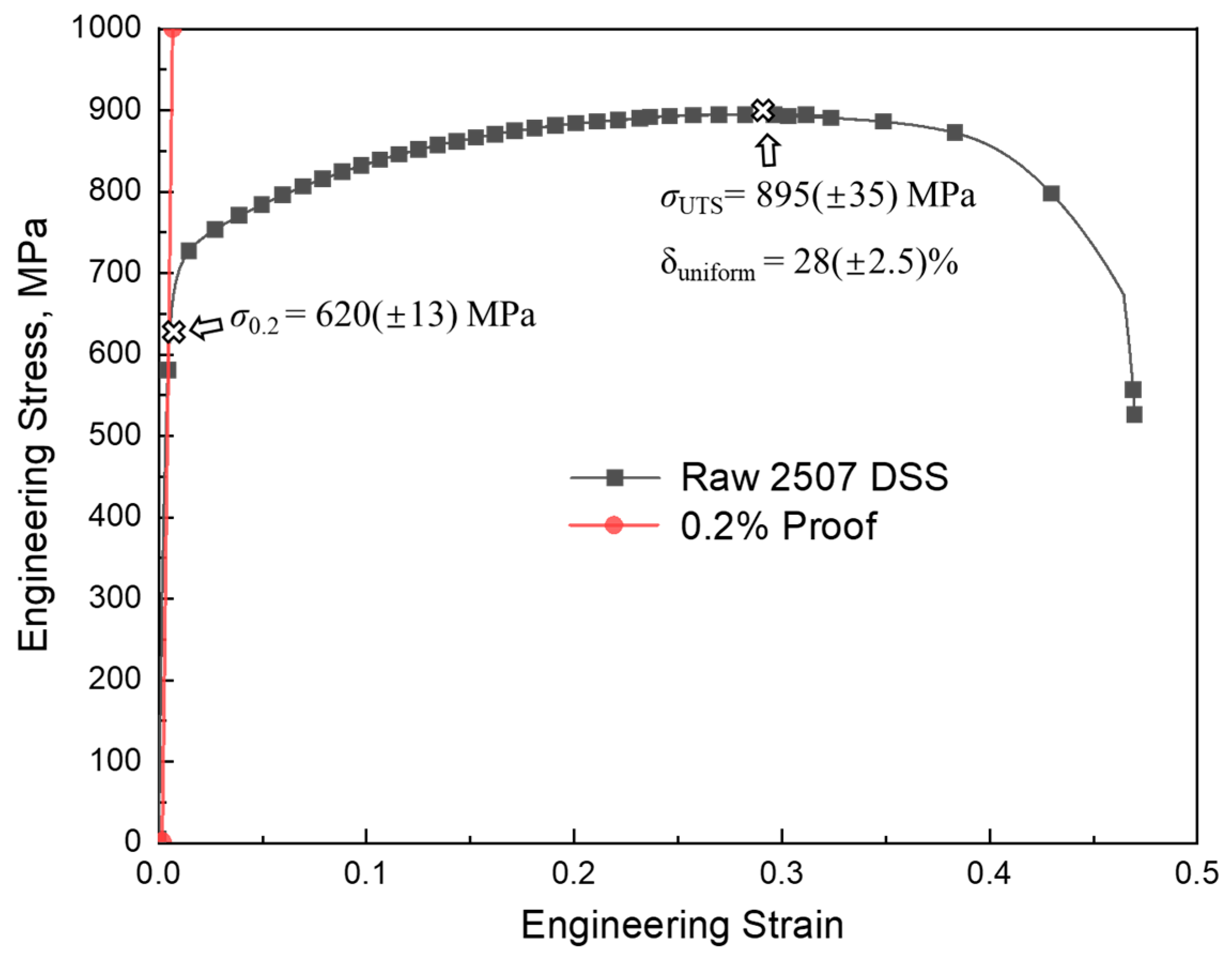
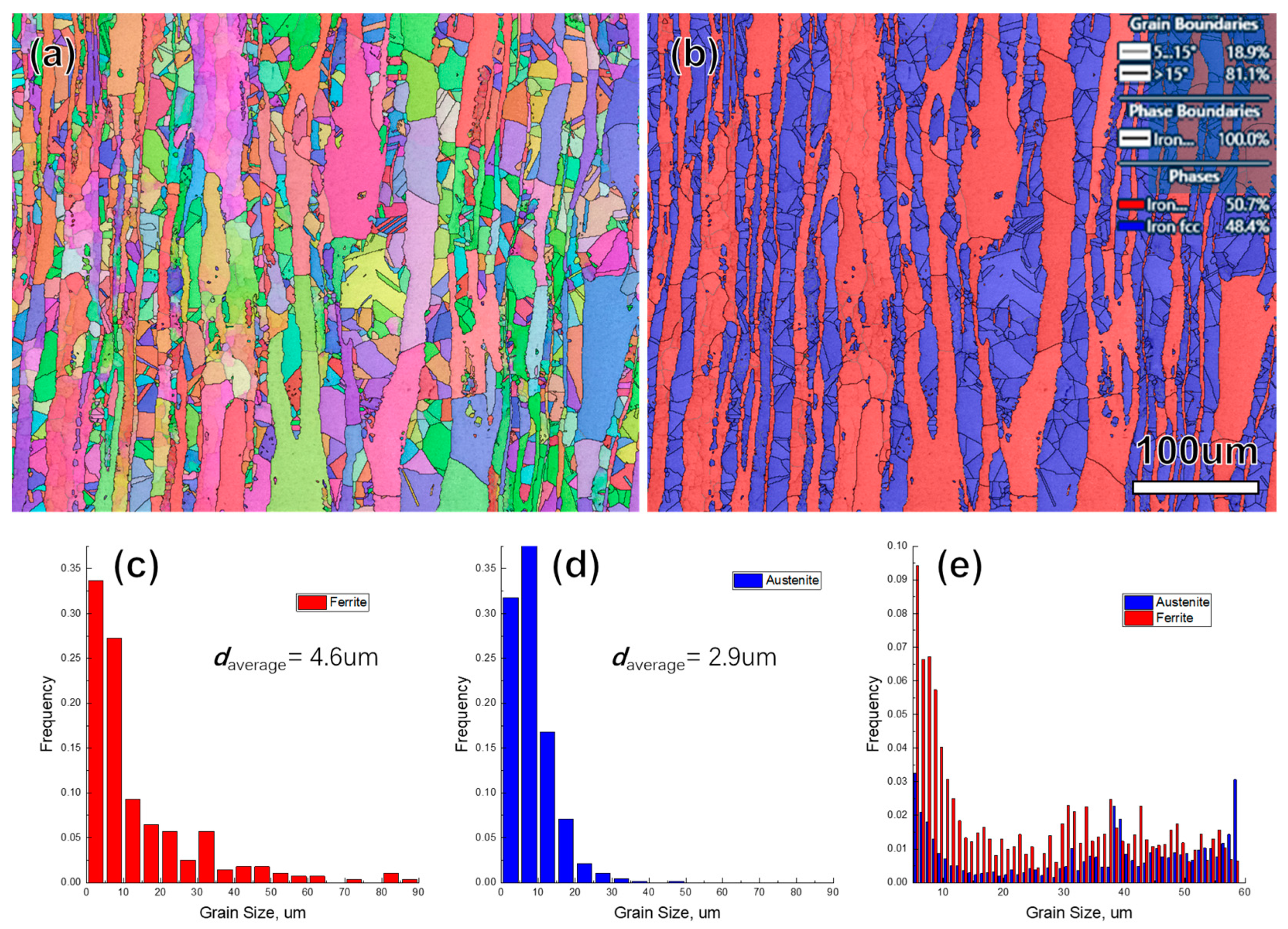
3.1. Mechanical Properties and Microstructure

Figure 1 shows the engineering stress–strain curve of the S32750 DSS rod with a diameter of 6 mm. The rod is strain-free without cold drawing deformation. The average values of the yield strength σ0.2, ultimate tensile strength σUTS, and uniform elongation δuniform are 620 (±13) MPa, 895 (±35) MPa, and 28 (±2.5) %, respectively. The engineering stress–strain curve exhibits a typical parabolic shape in the process of tensile straining. After reaching the yield point, the sustained strain-hardening behavior reveals an excellent flexibility of the raw S32750 DSS rod. When the uniform elongation reaches about 28%, the tensile strength reaches the peak value, and the ultimate tensile strength increases by nearly 300 MPa compared with the yield strength.
Figure 2 shows the microstructural characterizations of the hot-rolled S32750 DSS rod. The EBSD technique was employed to characterize and count the dual-phase fraction, morphology, and grain size in the longitudinal section of hot-rolled S32507 DSS. The EDX technique was employed to analyze the chemical composition of the dual phase. As indicated in the EBSD phase map (Figure 2b), blue and red represent the austenite and ferrite phases, respectively. Combined with the grain orientation diagram in Figure 2a, the ferrite grains are elongated and fibrous, while the austenite phase is composed of annealed equiaxed grains. The interphase distribution of the two phases limits the further growth of the grains. The grain size and misorientation of the ferrite and austenite phases were analyzed based on EBSD data. The ferrite grains exhibit a grain size ranging from 0 μm to 30 μm (average grain size is about 14.3 μm), and the size distribution interval of austenite grains (average grain size is about 8.3 μm) is significantly smaller than that of ferrite grains. Since the shape of the grain is not equiaxial, the diameter of the circle with equal area to the grain was employed to represent the grain size. In addition, the misorientation of the dual phases is dominated by grains with high-angle grain boundaries (HAGB). This microstructural characteristic proves that the dual phases have undergone a full recrystallization process. It is noteworthy that a large number of annealed twin boundaries (Σ3-GB, with a misorientation angle of 60°) are presented in the austenitic grains. The EDX results are presented in Table 3, revealing that the ferrite phase contains more chromium (28.4 wt%) and less nickel (5.0%), while austenite is just the opposite with 26.7 wt% of Cr and 6.6 wt% of Ni.

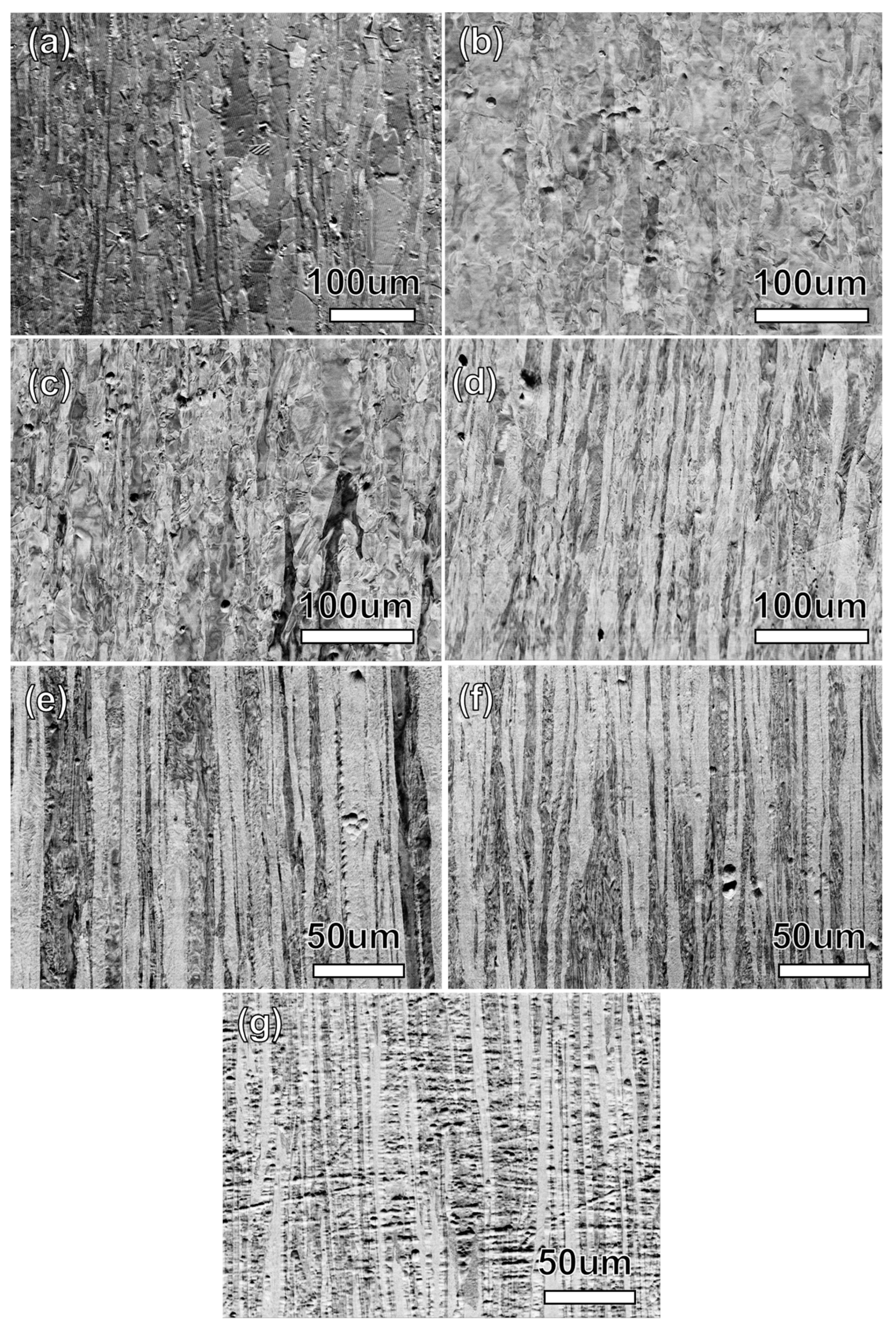
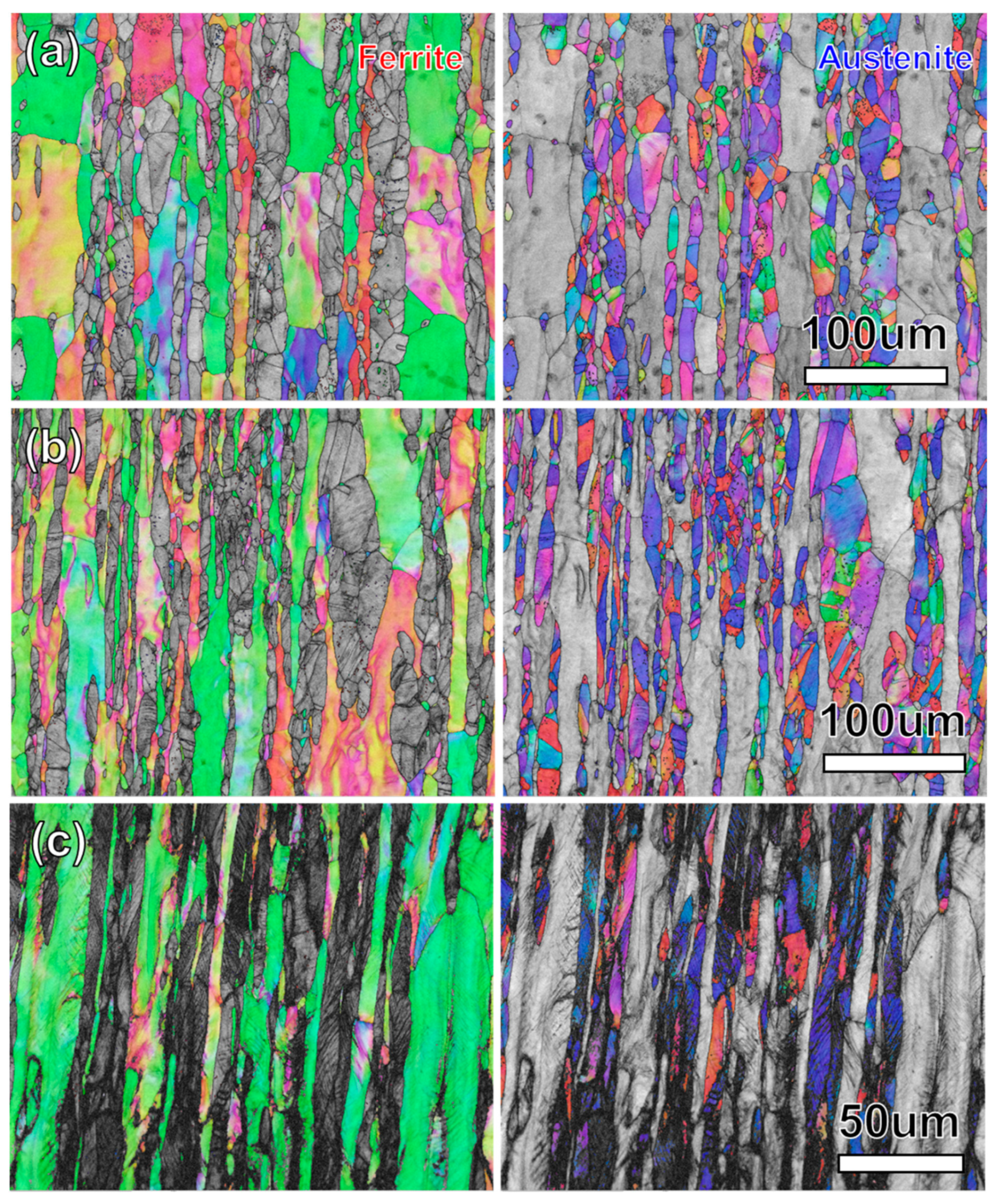
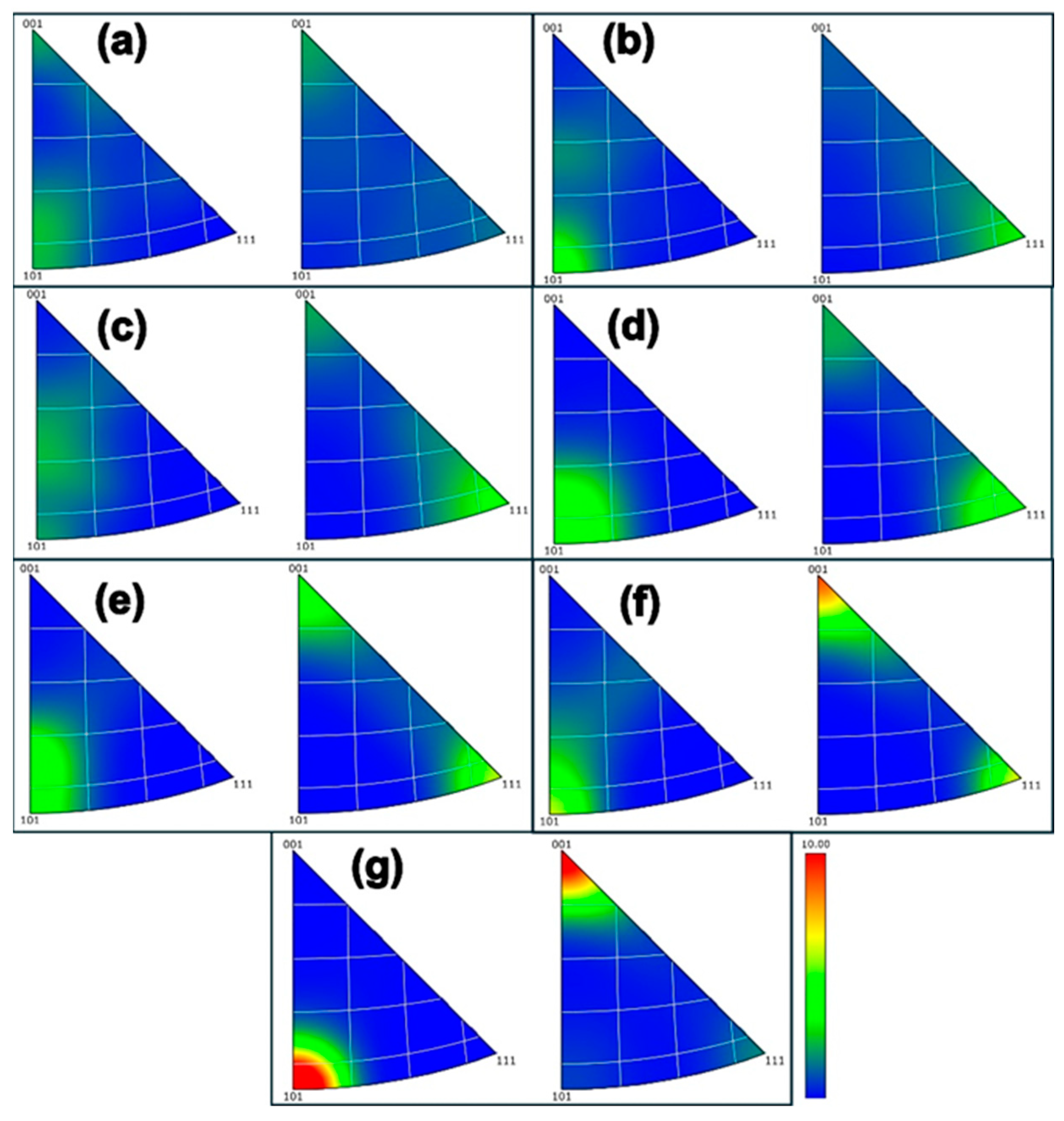
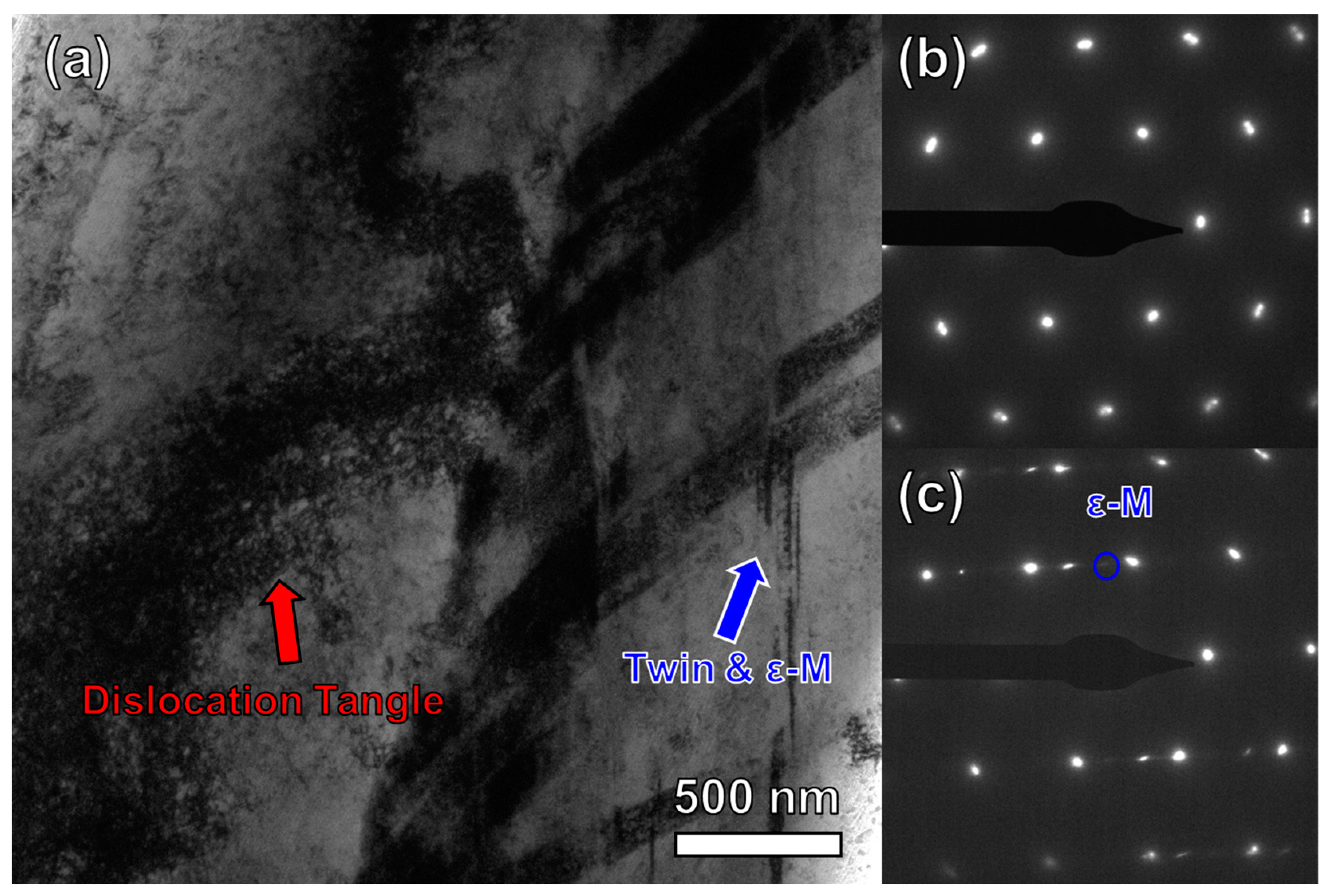
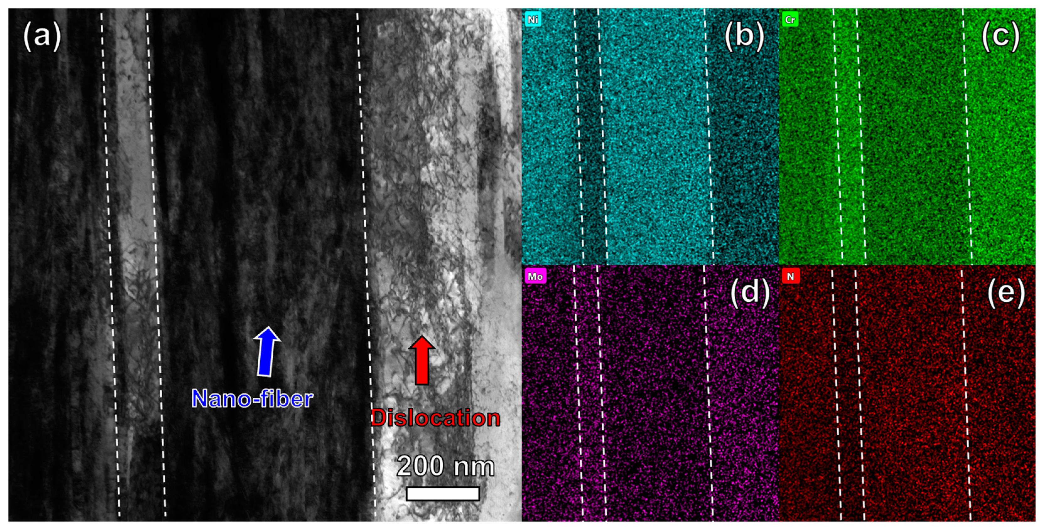
3.2. Microstructural Evolution of S32750 DSS Wires during Cold Drawing

The S32750 DSS rods with a diameter of 6 mm were cold drawn successively to a diameter of 1 mm, with a total cold drawing strain of 3.6. The corresponding cross-sectional area reduction ratio is about 97%. This cross-sectional area reduction can basically cover the process range of rolling and drawing deformation in industrial production.
The strength of the S32750 DSS wires increases rapidly after cold drawing deformation, as shown in Figure 3. The complete results of these tensile tests are presented in the inset of Figure 3 for the 0.2% proof yield strength and the tensile strength. At a low strain of ε = 0.8, cold-drawn S32507 DSS wire exhibits a yield strength of 1200 MPa and a tensile strength exceeding 1500 MPa. At a drawing strain of ε = 3.6, one can see that this S32507 DSS wire exhibits a high tensile strength close to 2000 MPa and a low ductility of about 2% (Figure 3). It is well known that the strain hardening of stainless steel wires caused by plastic deformation results in high strength at the expense of poor ductility (less than 5%). Taking the as-drawn S32750 DSS wire (a strain of 3.6) as an example, its yield strength is nearly three times that of the strain-free hot-rolled sample, and the ultimate tensile strength is more than two times greater. However, its uniform elongation is less than 2%, which is only one-fourth of the undeformed sample.
The evolution of the microstructure of cold-drawn S32750 DSS wire was analyzed by SEM electron channel contrast (ECC) images. The microstructure composed of the two phases is rapidly refined into a fibrous structure after severe cold-drawing deformation, as shown in Figure 4. The difference in element content in ferrite and austenite determines the difference in contrast in the ECC image. In Figure 4, the mismatch of the two-phase mechanical properties does not cause shear band or grain sliding deformation, and the two-phase morphology exhibited a uniform refinement process.
The EBSD technique was employed to analyze the microstructural evolution of the ferrite and austenite phases in the S32750 DSS wires. Figure 5a–c exhibits the EBSD maps of the S32750 DSS wires at different drawing strains (ε = 0.35, 0.8, and 1.4). With an increase in drawing strain, the dual-phase grains were rapidly refined. It is well known that the ferrite (BCC) phase in steel can only be deformed by dislocation gliding interactions, while austenite is deformed by dislocation gliding, twinning, and martensitic transformation [17,18]. The EBSD recognition rate of the austenite phase is high when the drawing strain is less than ε = 1.4, and the obvious twinning behaviors in austenite are observed. At low strain, the deformation mechanism for the austenite phase is dominated by dislocation and twinning. From the crystal orientation aspect, the maps of the ferrite phase are mainly green, indicating the dominance of the <110> fiber texture. In contrast, the austenite EBSD maps are dominated by blue and red, indicating that both the <111> and <001> fiber textures exist.
Figure 6a–c exhibits the EBSD maps of S32750 DSS wires at different drawing strains (ε = 2.2, 2.8 and 3.6). It can be seen that with the increase in drawing strain, the austenite is almost unable to be identified by the EBSD. The orientation of retained austenite grains is red, indicating a typical <100> texture feature. The texture feature is the direction of non-twinning deformation, and the part of austenite that cannot be identified by EBSD has been completely transformed into nanograins (black area). This microstructural characteristic indicates that the austenite undergoes twinning deformation, which induces a rapid grain refinement. Meanwhile, the austenite in S32750 is in a metastable phase; the austenite may also undergo deformation-induced martensitic transformation [19]. After a large deformation drawing, the ferrite phase is further refined into a fibrous structure, and there is also a sub-grain structure inside a ferrite fiber. At a strain of 3.6, the orientation color of the ferrite phase is almost completely green, indicating that it forms a single and strong <110> fiber texture.
The textural evolution of the S32750 dual-phase structure can be analyzed in detail by EBSD IPF maps. Compared with heavily drawn wires, the ferrite phase shows a lower intensity of <110> and <001> textures, and the austenite shows a weak <001> texture; the texture intensity of the two phases are both less than 2.5 in the strain-free hot-rolled rod (Figure 7). With an increase in drawing strain (ε < 2.2), the austenite gradually develops into <111> and <100> textures, which are the typical textures of an FCC metal during cold drawing process [20]. In case of higher drawing strain, the texture intensity in austenite increases rapidly, while the texture development is relatively slow. It is generally accepted that the <111> texture plays a dominant role in strained FCC metals. However, in the S32750 DSS wire with a cold drawing strain of ε = 3.6, the intensity of the <100> texture reaches 10, while that of the <111> texture is about 1.7. This may be due to the austenite possessing the <111> texture being rapidly refined into nanocrystals through twinning deformation or transformed into BCC phases by phase transformation [21,22]. The plastic deformation mechanism of FCC metals with a <100> texture is dislocation-dominated due to their lower Schmid factor along the tensile direction [23], so there is little refinement to the nanocrystals by twinning deformation. Since martensite transformation is followed by the twinning and ε-martensite transition, the martensite transition in the austenite with a <100> texture occurs slowly. Thus, the <100> texture is dominant in the austenite phase.

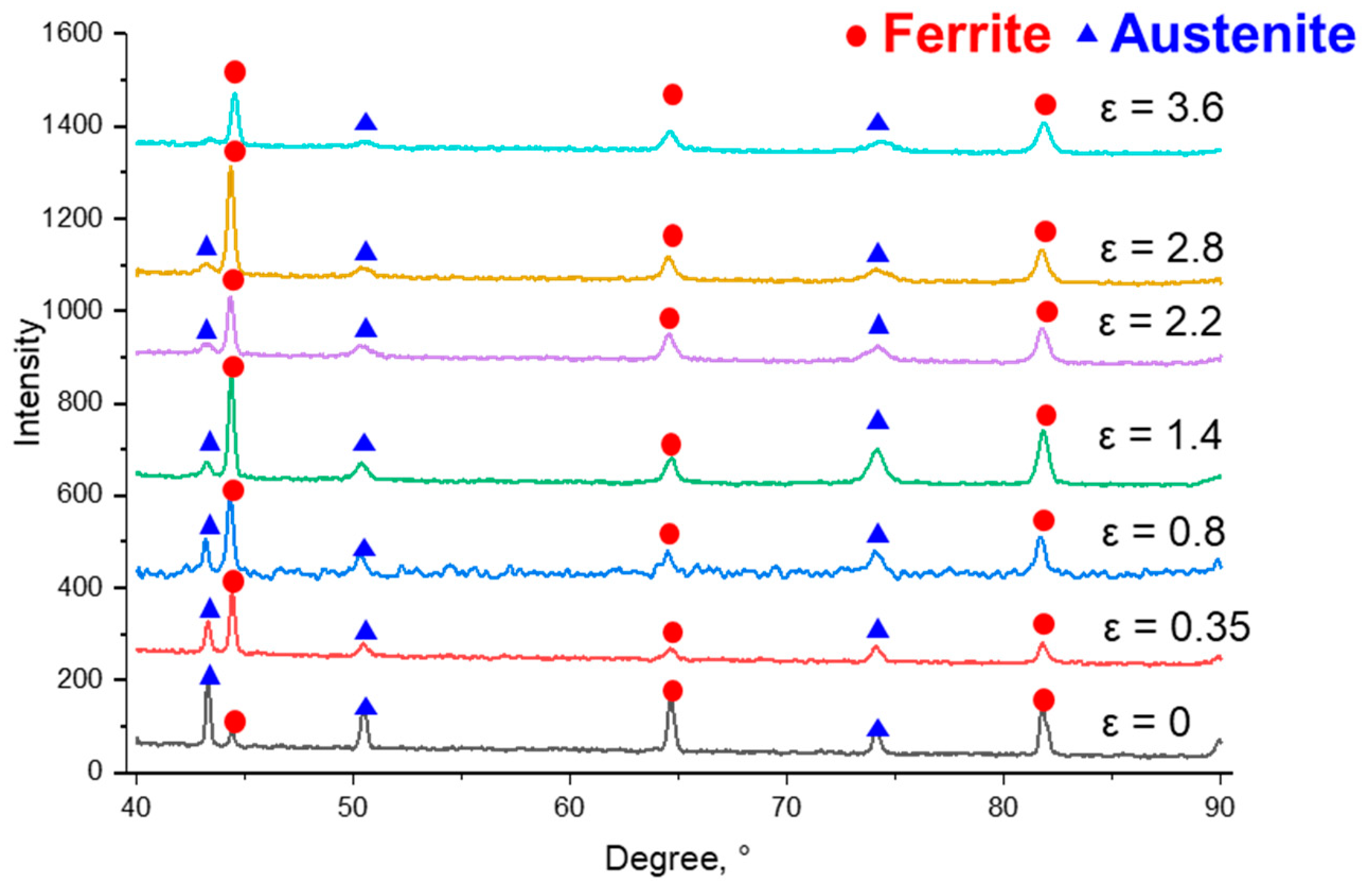
3.3. The Phase Transition of S32750 DSS Wires during Cold Drawing

Figure 8 shows the evolution of the dual phase in the S32750 DSS wires through X-ray diffraction analysis. The three strong peaks of austenite and ferrite phases can be detected in the strain-free rod. The relative intensity of the ferrite (110), (200), and (211) peaks gradually increase, while the relative intensity of the austenite peak decreased gradually with an increase in drawing strain. After the strain exceeds 2.2, the three strong peaks of austenite were quite low, confirming that the austenite has undergone strain-induced martensitic transformation, which is consistent with the EBSD results. The texture format during the cold drawing will also affect the intensity of the peaks; for example, the intensity of (200)Austenite became higher than that of the (111)Austenite when ε > 1.4.
Figure 9 exhibits the nanoindentation hardness of austenite and ferrite phases versus the drawing strains. It is generally believed that the austenite phase is the softer one when it is compared with the ferrite phase. As can be seen from Figure 9, the austenite in the drawn S32750 DSS wires exhibits a high hardening rate. When the drawing strain reached 0.8, the hardness of the austenite phase exceeded that of the ferrite. This result is mainly attributed to the twinning deformation mechanism of the austenite during the drawing, which hardens the austenite rapidly. The strengthened austenite phase was further strained in the next step—martensitic transformation—and the original austenite grains were replaced by nanoscale martensite grains [19]. The strain-induced martensite in the austenite should contribute to the hardness improvement continuously, since the EBSD and XRD result have revealed the strain-induced martensitic transition keeps occurring as the drawing strain increases. In addition, the continuous strain hardening ability of the ferrite phase with high initial hardness is insufficient [24].
TEM was used to analyze the microstructure of the ferrite and austenite in detail after being heavily drawn. Figure 10 shows the dual-phase microstructure of S32750 at a drawing strain of ε = 0.8. High-density dislocation was observed in the ferrite (referred to by the red arrow), and a straight band-like structure (referred to by the blue arrow) was also detected in austenite, as shown in Figure 10a. The corresponding SADE diffraction analysis in Figure 10c shows that the flat band structure should be a mixed structure of twinning and ε-martensite, indicating a stacking fault energy of austenite in S32750 of less than 20 mJ/m−2. The increased dislocation density and sub-grain structure in ferrite are the main microstructure characteristics at a strain of ε = 1.75 (as shown in Figure 11), which is consistent with the EBSD results. Thus, a fine and complex nano-lamellar structure is constructed in the austenite phase induced by massive twinning and ε-martensite interactions.
Figure 12 shows the TEM image of S32750 at a strain of ε = 3.6. Both ferrite and the original austenite in S32750 wire form a fibrous structure; the original two phases can be distinguished by the energy spectrum results. It can be seen from Figure 12a that the Ni-rich and Cr-poor austenite have been transformed into a fine nanofiber structure. The Cr-rich and Ni-poor ferrite forms a wide nanofiber crystal, which has a dense dislocation entanglement structure. The microstructure of the S32750 DSS wire is composed of two different sizes of grains, of which the finer originates from the initial austenite and the other from ferrite [24,25].

4. Discussion

In this study, the hot-rolled S32750 DSS rod is composed of a Ni-rich, Cr-poor austenite phase and a Cr-rich, Ni-poor ferrite phase. The proportion of the two phases is about 50%–50%. The two phases exhibit a different microstructural evolution during drawing. The deformed microstructure of the ferrite is simple due to its deformation mechanism being simple dislocation gliding. While the stacking fault energy of the austenite in S32750 is relatively low [13], the deformation production of the S32750 DSS during the drawing process is dislocation, SFs, and ε-martensite [26,27]. In fact, the metastable austenite phase in S32750 DSS will transform into α-martensite under strain. This phenomenon is further confirmed by the results of XRD and EBSD. However, the austenite grains with a <100> texture lacked twinning behavior during the plastic deformation process due to their low Schmid factors [23]. Thus, a subsequent α-martensite phase transformation did not occur in this austenite. The two-route deformation behavior of the two phases results in a heterogeneous microstructure in the heavily drawn S32750 DSS wires.
Due to the heterogeneous microstructure, the tensile strength of S32750 increases rapidly to near 2 GPa at a strain of ε = 3.6. Since the heterogeneous microstructure consisted of coarser ferrite and the finer two-phase mixed nanofiber, the strength contribution of the two parts should be considered individually. The coarser ferrite consists of a subgrain structure and high-density dislocations, and is similar to the cold-drawn iron wire, which has a strength of about 800 MPa at ε = 3.6 [28]. Considering the solid solution strengthening of Cr, Ni, Mo, and Si to the ferrite based on the predictive model by Galindo-Nava et al. [29], the strength of the ferrite should be about 1500 MPa. The initial austenite has been transited to a dual-phase mixed nanofibrous microstructure and should provide more strength for the S32750 DSS wires. Based on the general rule of mixtures, the strength contribution of the finer two-phase mixed nanofiber should be around 2400 MPa. The strength of such a heterogenous microstructure is not a single rule of mixtures, and back stress between the coarser ferrite and the finer two-phase mixed nanofiber is proposed to play a key role to determine the strength [30]. However, it could be concluded that the strengthening of S32750 DSS is mainly related to the microstructure refinement and excellent strain-hardening ability of the austenite phase.
The nanoindentation tests confirmed the above viewpoint. At first, the hardness of the austenite was lower than that of the ferrite, and it exceeded the latter at a drawing strain of ε= 0.8. At a drawing strain of ε= 3.6, the hardness of the original austenite structure was nearly 20% higher than that of ferrite. The significant strengthening of austenite during drawing is related to its strain-induced microstructural refinement. Through the evolutionary mechanism of SFs, ε martensite, and α-martensite, the original austenite evolved into a fine fibrous grain structure [31], as shown by the TEM EDX observation in Figure 12. According to the Hall–Petch relationship, this type of fine fibrous crystalline microstructure significantly contributes to strength compared to the coarser ferrite [32,33].

5. Conclusions

In this study, the microstructural evolution and strengthening mechanisms of S32750 DSS during the drawing process were investigated by mechanical property tests, EBSD, and TEM. The main conclusions are summarized as follows:
(1) The yield strength and ultimate tensile strength of S32750 DSS wire at a strain of ε = 3.6 reach 1771 MPa and 1952 MPa, respectively, which are 2.9 and 2.2 times that of the initial rods.
(2) The deformation production of the austenite phase in S32750 DSS during the drawing process is dislocation, SFs, ε-martensite, and α-martensite. Through the evolution process, the original austenite has evolved into a fine nanofibrous structure.
(3) The microstructure of the S32750 DSS wire evolved into a heterogeneous structure, consisting of nanofibrous grains originating from austenite and the relatively coarser ferrite fiber grains. This heterogeneous structure contributes to drawing strengthening of the S32750 DSS wire.

Author Contributions

Conceptualization, H.G. and L.Z. (Lichu Zhou); methodology, Z.A., L.Y. and J.W.; formal analysis, H.G., L.Z. (Lichu Zhou) and X.C.; investigation, Z.A.; data curation, L.Z. (Lili Zhai), B.D. and J.P.; writing—original draft preparation, H.G.; writing—review and editing, L.Z. (Lichu Zhou); supervision, L.Z. (Lichu Zhou) and H.G.; funding acquisition, H.G. and L.Z. (Lichu Zhou). All authors have read and agreed to the published version of the manuscript.

Funding

This research was funded by the Jiangsu Key Laboratory of Advanced Metallic Materials, Southeast University, PR China (No. AMM2023B04).

Data Availability Statement

The raw/processed data required to reproduce these findings cannot be shared at this time as it is also part of an ongoing study.

Conflicts of Interest

Hong Gao, Lili Zhai, and Jin Peng are employed by the company Jiangsu Wujin Stainless Steel Pipe Group Co., Ltd. Liang Yao, Jianyong Wang, and Binhua Ding are employed by the company Yongxing Special Materials Technology Co., Ltd. The remaining authors declare that the research was conducted in the absence of any commercial or financial relationships that could be construed as a potential conflict of interest.

References

  1. Chen, T.H.; Weng, K.L.; Yang, J.R. The effect of high-temperature exposure on the microstructural stability and toughness property in a 2205 duplex stainless steel. Mater. Sci. Eng. A 2002, 338, 259–270. [Google Scholar] [CrossRef]
  2. Cobb, H.M. The History of Stainless Steel; ASM International: Materials Park, OH, USA, 2010. [Google Scholar]
  3. Olsson, J.; Snis, M. Duplex—A new generation of stainless steels for desalination plants. Desalination 2007, 205, 104–113. [Google Scholar] [CrossRef]
  4. Geng, S.; Sun, J.; Guo, L.; Wang, H. Evolution of microstructure and corrosion behavior in 2205 duplex stainless steel GTA-welding joint. J. Manuf. Process. 2015, 19, 32–37. [Google Scholar] [CrossRef]
  5. Patra, S.; Agrawal, A.; Mandal, A.; Podder, A.S. Characteristics and manufacture ability of duplex stainless steel: A review. Trans. Indian Inst. Met. 2021, 74, 1089–1098. [Google Scholar] [CrossRef]
  6. Sato, Y.S.; Nelson, T.W.; Sterling, C.J.; Steel, R.J.; Pettersson, C.-O. Microstructure and mechanical properties of friction stir welded 2507 super duplex stainless steel. Mater. Sci. Eng. A 2005, 880, 376–384. [Google Scholar] [CrossRef]
  7. Lo, K.H.; Shek, C.H.; Lai, J.K.L. Recent developments in stainless steels. Mater. Sci. Eng. Rep. 2009, 65, 39–104. [Google Scholar] [CrossRef]
  8. Jeon, S.-H.; Kim, S.-T.; Lee, I.-S.; Kim, J.-S.; Kim, K.-T.; Park, Y.-S. Effects of W substitution on the precipitation of secondary phases and the associated pitting corrosion in hyper duplex stainless steels. J. Alloys Compd. 2012, 544, 166–172. [Google Scholar] [CrossRef]
  9. Luchtenberg, P.; de Campos, P.T.; Soares, P.; Laurindo, C.A.H.; Maranho, O.; Torres, R.D. Effect of welding energy on the corrosion and tribological properties of duplex stainless steel weld overlay deposited by GMAW/CMT process. Surf. Coat. Technol. 2019, 375, 688–693. [Google Scholar] [CrossRef]
  10. Tao, N.R.; Lu, K. Nanoscale structural refinement via deformation twinning in face-centered cubic metals. Scr. Mater. 2009, 60, 1039–1043. [Google Scholar] [CrossRef]
  11. Dehsorkhi, N.R.; Sabooni, S.; Karimzadeh, F.; Rezaeian, A.; Enayati, M.H. The effect of grain size and martensitic transformation on the wear behavior of AISI 304L stainless steel. Mater. Des. 2014, 64, 56–62. [Google Scholar] [CrossRef]
  12. Yan, F.K.; Liu, G.Z.; Tao, N.R.; Lu, K. Strength and ductility of 316L austenitic stainless steel strengthened by nano-scale twin bundles. Acta Mater. 2012, 60, 1059–1071. [Google Scholar] [CrossRef]
  13. Li, Q.; Zhou, L.; Pan, Y.; Ma, J.; Zhou, X.; Jiang, H.; Xie, Z.; Fang, F. Formation of nano martensite grain with specific angle grain boundary during the drawing process of 316L stainless steel. Mater. Sci. Eng. A 2024, 897, 146309. [Google Scholar] [CrossRef]
  14. Wang, B.; Wang, Q.; Luo, R.; Kan, Q.; Gu, B. Atomistic study on high temperature creep of nanocrystalline 316L austenitic stainless steels. Acta Mech. Sin. 2023, 39, 122470. [Google Scholar] [CrossRef]
  15. Herrera, C.; de Lima, N.B.; Kliauga, A.M.; Padilha, A.F. Microstructure and texture of duplex stainless steel under melt spinning processing. Mater. Charact. 2008, 59, 79–83. [Google Scholar] [CrossRef]
  16. Rodrigues, D.G.; Maria, G.G.B.; Viana, N.A.L.; Santos, D.B. Effect of low cold-rolling strain on microstructure, texture, phase transformation, and mechanical properties of 2304 lean duplex stainless steel. Mater. Charact. 2019, 150, 138–149. [Google Scholar] [CrossRef]
  17. Welsch, E.; Ponge, D.; Haghighat, S.M.H.; Sandlöbes, S.; Choi, P.; Herbig, M.; Zaefferer, S.; Raabe, D. Strain hardening by dynamic slip band refinement in a high-Mn lightweight steel. Acta Mater. 2016, 116, 188–199. [Google Scholar] [CrossRef]
  18. Yang, Z.; Lu, S.; Tian, Y.; Gu, Z.; Sun, J.; Vitos, L. Theoretical and experimental study of phase transformation and twinning behavior in metastable high-entropy alloys. J. Mater. Sci. Technol. 2022, 99, 161–168. [Google Scholar] [CrossRef]
  19. Wroński, S.; Tarasiuk, J.; Bacroix, B.; Baczmański, A.; Braham, C. Investigation of plastic deformation heterogeneities in duplex steel by EBSD. Mater. Charact. 2012, 73, 52–60. [Google Scholar] [CrossRef]
  20. Arya, A.; Suwas, S.; Gérard, C.; Signor, L.; Thilly, L.; Chokshi, A.H. Strength and microstructure evolution in nickel during large strain wire drawing. Acta Mater. 2021, 221, 117396. [Google Scholar] [CrossRef]
  21. Kwon, E.P.; Fujieda, S.; Shinoda, K.; Suzuki, S. Characterization of transformed and deformed microstructures in transformation1induced plasticity steels using electron backscattering diffraction. Mater. Sci. Eng. A 2011, 528, 5007–5017. [Google Scholar] [CrossRef]
  22. Zieliński, W.; Świątnicki, W.; Barstch, M.; Messerschmidt, U. Non-uniform distribution of plastic strain in duplex steel during TEM in situ deformation. Mater. Chem. Phys. 2003, 81, 476–479. [Google Scholar] [CrossRef]
  23. Lemarquis, L.; Giroux, P.-F.; Maskrot, H.; Castany, P. Activated twinning variant determination in cold-rolled 316 L stainless steel by effective Schmid factor analysis. Materialia 2023, 30, 101812. [Google Scholar] [CrossRef]
  24. Huang, C.X.; Yang, G.; Gao, Y.L.; Wu, S.D.; Li, S.X. Investigation on the nucleation mechanism of deformation-induced martensite in an austenitic stainless steel under severe plastic deformation. J. Mater. Res. 2011, 22, 724–729. [Google Scholar] [CrossRef]
  25. Zhou, T.; Xiong, Y.; Yue, Y.; Lu, Y.; Chen, Y.-N.; He, T.-T.; Ren, F.-Z.; Singh, H.; Kömi, J.; Huttula, M.; et al. Controlled cold rolling effect on microstructure and mechanical properties of Ce-modified SAF 2507 super duplex stainless steel. Mater. Sci. Eng. A 2019, 766, 138352. [Google Scholar] [CrossRef]
  26. Yin, F.; Cheng, G.J.; Xu, R.; Zhao, K.; Li, Q.; Jian, J.; Hu, S.; Sun, S.; An, L.; Han, Q. Ultrastrong nanocrystalline stainless steel and its Hall-Petch relationship in the nanoscale. Scr. Mater. 2018, 155, 26–31. [Google Scholar] [CrossRef]
  27. Zhou, L.C.; Fang, F.; Zhou, J.; Xie, Z.; Jiang, J. Strain-induced coarsening of ferrite lamella in cold drawn pearlitic steel wire. Mater. Sci. Eng. A 2020, 771, 138602. [Google Scholar] [CrossRef]
  28. Feng, H.; Fang, F.; Zhou, X.; Zhang, X.; Xie, Z.; Jiang, J. Heavily cold drawn iron wires: Role of nano-lamellae in enhancing the tensile strength. Mater. Sci. Eng. A 2020, 796, 140017. [Google Scholar] [CrossRef]
  29. Galindo-Nava, E.I.; Rivera-Díaz-del-Castillo, P.E.J. A model for the microstructure behaviour and strength evolution in lath martensite. Acta Mater. 2015, 98, 81–93. [Google Scholar] [CrossRef]
  30. Yang, M.; Pan, Y.; Yuan, F.; Zhu, Y.; Wu, X. Back stress strengthening and strain hardening in gradient structure. Mater. Res. Lett. 2016, 4, 145–151. [Google Scholar] [CrossRef]
  31. Nakada, N.; Ito, H.; Matsuoka, Y.; Tsuchiyama, T.; Takaki, S. Deformation-induced martensitic transformation behavior in cold-rolled and cold-drawn type 316 stainless steels. Acta Mater. 2010, 58, 895–903. [Google Scholar] [CrossRef]
  32. Saeidi, K.; Kevetkova, L.; Lofaj, F.; Shen, Z. Novel ferritic stainless steel formed by laser melting from duplex stainless steel powder with advanced mechanical properties and high ductility. Mater. Sci. Eng. A 2016, 665, 59–65. [Google Scholar] [CrossRef]
  33. Shirdel, M.; Mirzadeh, H.; Parsa, M.H. Nano/ultrafine grained austenitic stainless steel through the formation and reversion of deformation-induced martensite: Mechanisms, microstructures, mechanical properties, and TRIP effect. Mater. Charact. 2015, 103, 150–161. [Google Scholar] [CrossRef]
Figure 1. Engineering stress–strain curve of the hot-rolled S32750 DSS wire without cold drawing.
Crystals 14 00621 g001
Figure 2. EBSD characterizations obtained from the longitudinal section of hot-rolled S32750 DSS wire without cold drawing. (a) EBSD-IPFx map shows the ferrite and austenite; (b) EBSD phase map; (c) Grain-size distribution of ferrite phase in (a); (d) Grain size distribution of austenite phase in (a); and (e) Grain size distribution of dual phases in (a).
Crystals 14 00621 g002
Figure 3. (a) Engineering stress–strain curves of the hot-rolled S32750 DSS wire at different cold drawing strains (the inset shows the values of yield strength σ0.2 and ultimate tensile strength σUTS and the fracture of the wire at ε = 3.6). (b) The ultimate tensile strength and uniform elongation versus drawing strain.
Crystals 14 00621 g003
Figure 4. The ECC images obtained from the longitudinal section of S32750 DSS wires at different drawing strains. (a) ε = 0; (b) ε = 0.35; (c) ε = 0.8; (d) ε = 1.4; (e) ε = 2.2; (f) ε = 2.8; and (g) ε = 3.6.
Crystals 14 00621 g004
Figure 5. Electron backscattered (EBSD) maps of S32750 DSS wires at different drawing strains. (a) ε = 0.35; (b) ε = 0.8; and (c) ε = 1.4.
Crystals 14 00621 g005
Figure 6. Electron backscattered (EBSD) maps of S32750 DSS wires at different drawing strains. (a) ε = 2.2; (b) ε = 2.8; and (c) ε = 3.6.
Crystals 14 00621 g006
Figure 7. Electron backscattered (EBSD) inverse pole figure (IPF) maps of S32750 DSS wires at different drawing strains. (a) ε = 0; (b) ε = 0.35 (c) ε = 0.8; (d) ε = 1.4; (e) ε = 2.2; (f) ε = 2.8; and (g) ε = 3.6.
Crystals 14 00621 g007
Figure 8. X-ray diffraction patterns of ferrite and austenite in S32750 DSS wires at different strains.
Crystals 14 00621 g008
Figure 9. The nanoindentation hardness of austenite and ferrite phases versus strain.
Crystals 14 00621 g009
Figure 10. Bright-field TEM images showing the dislocation and band-like structures of S32750 DSS wires at a strain of 0.8. (a) TEM bright field images; (b) selected area electron diffraction (SAED) of ferrite phase; and (c) SAED corresponding to twins and ε-martensite in the austenite phase.
Crystals 14 00621 g010
Figure 11. Bright-field TEM images of S32750 DSS wires at a strain of 1.75. (a) shows sub-grains and (b) shows twin and ε-martensite.
Crystals 14 00621 g011
Figure 12. Bright-field TEM images of S32750 DSS wires at a strain of 3.6. (a) shows nano-lamellar structure and (b) the corresponding EDS mapping of Ni, (c) the corresponding EDS mapping of Cr, (d) the corresponding EDS mapping of Mo, (e) the corresponding EDS mapping of N.
Crystals 14 00621 g012
Table 1. The chemical composition of the S32750 stainless steel, wt%.
ElementCCrNiMoSiFe
Mass, %<0.0326.96.43.60.5Bal.
Table 2. The diameters and corresponding drawing strain of the wires tested in this study.
Diameter, mm65.044.022.9821.481
Drawing strain ε00.350.81.42.22.83.6
Table 3. The chemical composition of the ferrite and austenite phase in S32750 stainless steel, in wt%.
ElementCCrNiMoSiFe
Ferrite<0.0328.45.04.20.5Bal.
Austenite<0.0326.76.63.50.5Bal.
Disclaimer/Publisher’s Note: The statements, opinions and data contained in all publications are solely those of the individual author(s) and contributor(s) and not of MDPI and/or the editor(s). MDPI and/or the editor(s) disclaim responsibility for any injury to people or property resulting from any ideas, methods, instructions or products referred to in the content.

