Article

Evolution of the Microstructure, Phase Composition and Thermomechanical Properties of the CuZnIn Alloys, Achieved by Thermally Controlled Phase Transitions

Institute of Metallurgy and Materials Science, Polish Academy of Sciences (PAS), 30-059 Krakow, Poland
*
Authors to whom correspondence should be addressed.
Crystals 2024, 14(7), 669; https://doi.org/10.3390/cryst14070669
Submission received: 21 June 2024 / Revised: 12 July 2024 / Accepted: 16 July 2024 / Published: 22 July 2024

Abstract

:
Ternary alloys with CuZnIn compositions based on the binary CuZn diagram and the modeled ternary system solidus projection were investigated. The as-cast alloys, hot-rolled sheets, and samples annealed at low temperature were examined. It was found that the α-CuZn solution phase, with minor indium additions (1–2% at.), was the primary phase crystallizing during casting and remained stable at low temperatures. The ternary phase with an approximate composition of Cu8(In,Zn)4.5 and a structure analogous to the high-temperature γ-Cu9In4 phase crystallized from the liquid state and remained stable at low temperatures. This behavior results from the stabilization against peritectoidal decomposition by the Zn atoms when substituting In in the structure. A new phase γ*-Cu9(In,Zn)4 with a modified structure was identified, characterized by a reduced unit cell and an altered electronic structure. The hot-rolling process preserves the phase composition and forms a composite-like structure, with the matrix composition of γ* and large ellipsoidal α-CuZn solution particles. On a microscale, the γ* matrix exhibited a specific structure resulting from segregation processes and was composed of micrometer-sized α-CuZn(In) solution particles and nano-sized β-CuZn phase precipitates. Low-temperature annealing intensifies the γ* matrix decomposition through binary phase precipitation.

1. Introduction

The binary systems CuZn [1,2], CuIn [3,4] (Figure 1), and InZn [5] are well-studied and may be the basis for the simplified modeling of the ternary system within the CALPHAD framework. However, the lack of sufficient thermodynamic data limits the reliability of such simulations. The CuIn and CuZn systems contain solid solutions and intermetallic phases [1,2,3,4], whereas the InZn system exhibits lack of solubility [5]. In the CuZn and CuIn systems, solubility in copper initially increases and then decreases with decreasing temperature. At higher Zn and In contents, this process leads to the precipitation and decomposition of the solution. In the CuIn system, the solubility of indium reaches a maximum at 10% at., and the precipitation of the β-Cu8In2, η’-Cu9In5 and δ-Cu7In3 phases occurs below 616 °C, causing the phase composition at low temperatures to differ from that at high temperatures (Figure 1). Thermodynamic studies [6,7] indicate that at the equilibrium state in the ternary system only the binary phases should exist, although the possibility of metastable ternary phases cannot be excluded.
Some investigations presented in the literature concerned lead-free solders, mainly binary Zn-based, with low temperature additions like In, Sn, and Bi supplying valuable information about ZnIn alloys’ properties and interactions with the Cu as a substrate [8,9,10]. Such solders could replace very expensive AuSi or AuSn alloys [8,10]. It was also expected that the ternary CuZnIn alloys with small In additions could be used as lead-free solders with a high soldering temperature, though the lack of a significant effect of indium on lowering the melting temperature limits their application for soft soldering [11].
For some time, a renewed interest in the CuZn system has been observed in the literature, which has focused on modelling the phases’ structure, physical, mechanical and thermodynamic properties [12,13,14,15]. The enhanced mechanical properties of CuZn alloys are crucial for different industrial applications [13]. All published investigations concern compositions in the range of the Cu solid solutions, with a small In additions. In practice, alloy design requires knowledge of phase equilibria, microstructure, and alloy properties to tailor the composition to the specific application requirements [16]. The ternary phase diagram for the CuZnIn system has not been known in the literature until now, and the published results thus far only pertain to small additions of indium to CuZn alloys within the solution range. The effects of large indium additions, which, based on the CuZn system, should place the phase composition of the alloys at the boundary of the α phase with an α fcc structure or within the α + β (bcc) two-phase field, have not been investigated. A lot of experiments and thermodynamic data are required to create such a ternary system. The motivation for this research was the lack of data in the literature regarding phase characteristics, equilibria, the possibility of ternary phases (both equilibrium and metastable), and the potential application properties of the alloys in this system. An additional motivation was the significant differences in the properties exhibited by the individual components of this system, such as Cu, which has an easily deformable fcc structure and high melting point; Zn, which has a hexagonal structure with an easy slip system and high hardness; and In, which has a very low melting point and thus high deformability and extremely low strength. Based on studies of the phases obtained by diffusion joints in the CuZnIn ternary system [17], and taking into account the facts presented earlier, it was hypothesized that it would be possible to obtain a ductile fcc solid solution reinforced with the β-CuZn phase precipitates of bcc structure, enriched with In; however, the participation of the phases from the CuIn system should be expected.
The research presented in the current paper pertains to cast ternary alloys within the solid solution range, with an indium content of 4–7% at., expected to possess α + β two-phase composition with participation of the ternary phase. This study is limited to the high copper and zinc content, excluding compositions with a dominant indium content due to their low thermal stability and mechanical strength. To evaluate the application properties of selected alloys within the copper solution range, they were subjected to hot rolling, resulting in sheets with a complex structure and a phase composition resembling a natural composite. These were processed by hot rolling into sheets with a thickness range of 0.4–0.7 mm. Further, to reveal the thermal stability of the phase composition and the microstructure at low temperatures, the hot-rolled samples were annealed at 200 °C for 120 h. Thermomechanical tests were also performed to determine the temperature range of the elastic and plastic deformability of the alloys.

2. Materials and Methods

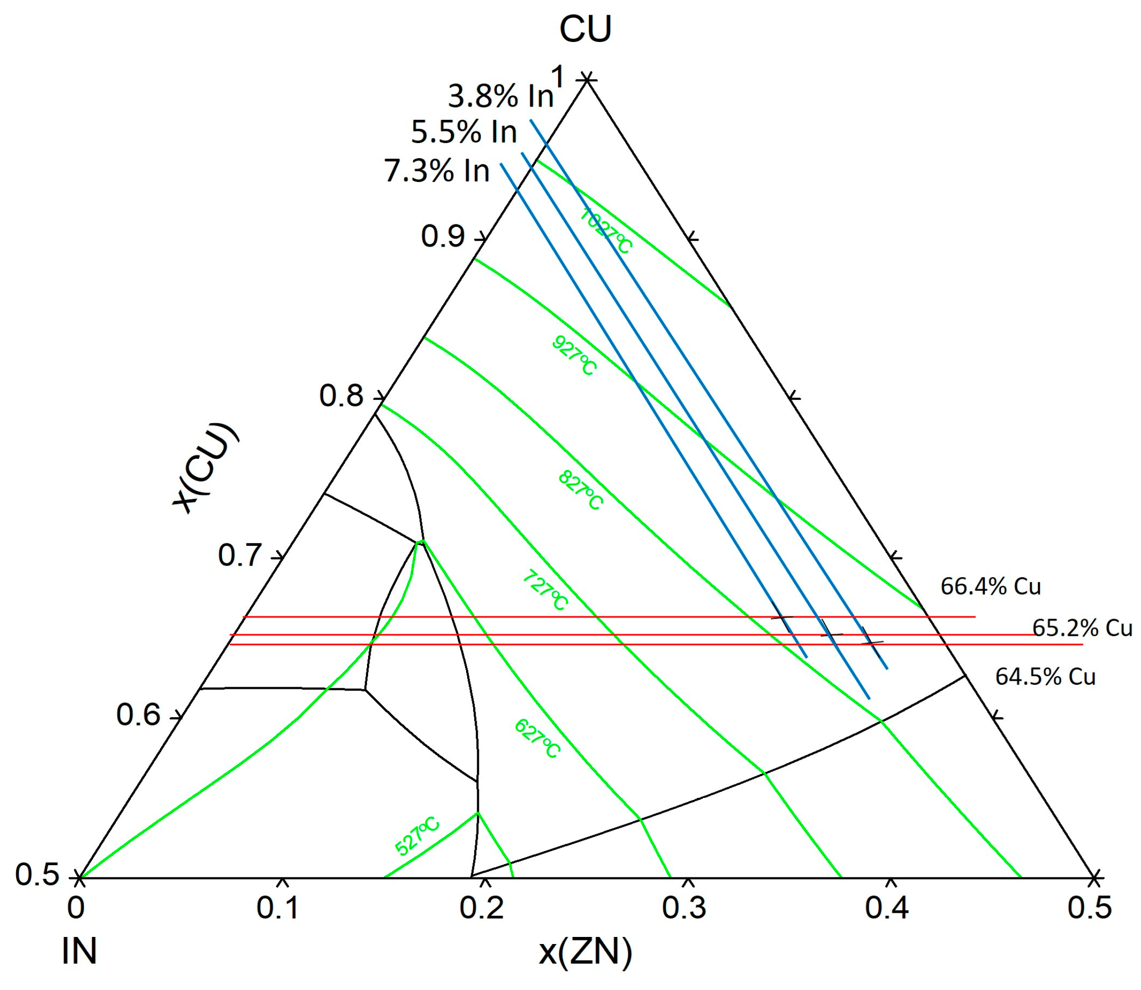
The three investigated alloys of the compositions shown in Figure 2 and Table 1 were produced using classical metallurgy methods, i.e., melted under a salt layer in a muffle furnace and cast into a steel mold. Furthermore, the alloys were subjected to a two-stage hot rolling process at 600 °C, followed by water quenching and annealing at 200 °C for 120 h. During annealing, the samples were enclosed in an argon atmosphere in a quartz crucible. The composition of the alloys and designations of the studied samples are presented in Table 1.
The composition of the investigated samples is shown in Figure 2, in relation to the projection of the solidus temperature isotherms on the ternary composition triangle, modeled with the PANDAT software (ver. 2013). The simplified PANDAT modeling, based on the predictions from the binary phase diagrams, made the phase boundaries somehow hypothetical.
All the alloys’ compositions investigated in the study are located in the Cu solid solution phase field, near to the boundary with the β phase crystallization phase field. Investigations of the phase composition of alloys and the microstructure were conducted both for the as-cast state (designated as A, Table 1), after double hot rolling (designated as C, Table 1), and after a final annealing of the samples at 200 °C for 120 h (designated as D, Table 1). The thermomechanical properties of the samples from series C were also investigated. The following methodology was applied:
  • The microstructural characterization and determination of chemical composition were carried out on the samples’ cross-sections using the FEI QUANTA 3D FEGSEM scanning electron microscope (SEM), ThermoFisher Sci., Brno, Czech Republic equipped with the EDAX-EDXS energy-dispersive X-ray spectrometer. Qualitative changes in composition were observed in the backscattered electron (BSE) mode. The investigations were conducted in high vacuum conditions (106 mbar) at the accelerating voltage of 20 keV. Microstructural evolution, due to the annealing at 200 °C, was examined using electron backscatter diffraction (EBSD) with the TSL EBSD system. The composition maps were obtained in the plane perpendicular to the transverse rolling direction (ND/RD). Samples’ surfaces were prepared by vibratory polishing using a Master Met2 silicon suspension. The following parameters were used for the EBSD measurements: tilt angle = 70°, voltage = 20 kV, working distance = 10.0 mm and mapping step size = 0.27 µm.
  • An X-ray structural analysis of the alloys was performed with use of the D8 Bruker diffractometer, Germany with Co Kα radiation, operated at 40 kV/45 mA, with a standard holder. Measurements were conducted in the 2θ range of 20–100°, with the scanning step of 0.02°. For the phase identification, the PDF4+(ver. 2023) crystallographic database and the program Diffrac.EVA V.3.0 was applied. Investigations were conducted both on cross-sectional and longitudinal sample sections.
  • The thermomechanical analysis (TMA) of the hot-rolled samples was performed with the use of the Netzsch TMA 402 F1 Hyperion instrument, Selb, Germany. The analysis was conducted using the tensile mode with a constant tensile loading (2.5 N) and heating rate of 5 °C/min, in the temperature range RT-650 °C. The ceramic active measuring elements used were made from alumina, and a high-purity helium protective atmosphere was used. The samples for the tensile experiment in TMA were prepared in the form of rectangles 20.5 mm × 1.0 mm with the thickness 0.6 mm. The surface was polished with sand paper and polishing grazes to the mirror state.
  • For the transmission electron microscopy (TEM/HRTEM) studies, the FEI TECNAI G2 FEG/200 kV microscope, equipped with the high-angle annular dark-field detector (HAADF) and the EDAX Phoenix EDS spectrometer, was used. Thin foils for TEM were prepared by electrochemical polishing in the HNO3/methanol solution, supplemented with the ion milling.
  • The electronic structure of the Cu9In4-type ternary phase was determined by applying density functional theory (DFT). DFT calculations were performed using Quantum Espresso (ver. 2023) software at the computing center HPC “ACK Cyfronet AGH” on the Ares Supercomputer, under computational grant no. PLG/2023/016473. The cell parameters of the samples, investigated on their cross-sectional and longitudinal sections, were calculated using the Nelson–Riley extrapolation method.

3. Results and Discussion

3.1. Microstructure and Phase Composition

3.1.1. As-Cast Alloys

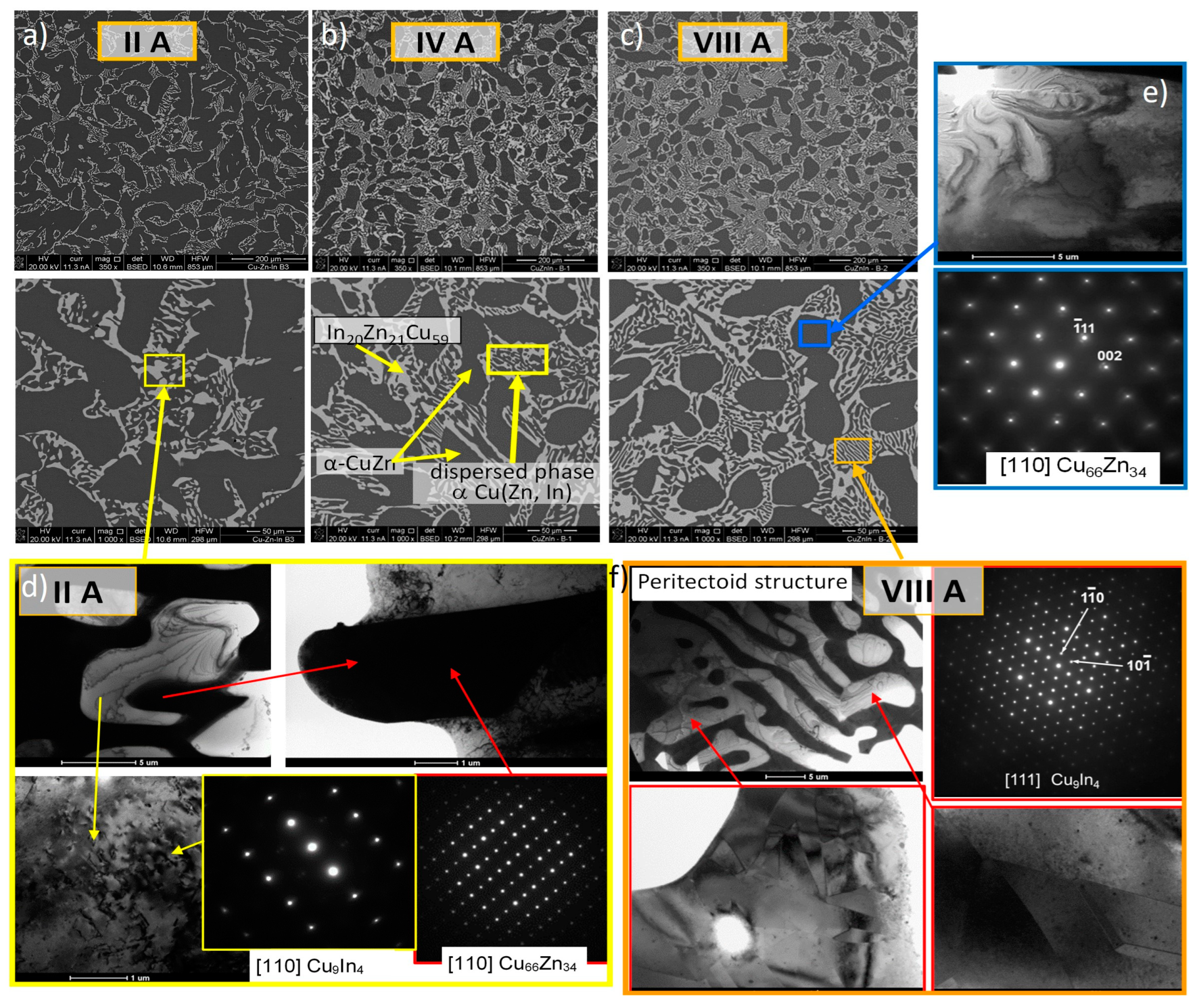
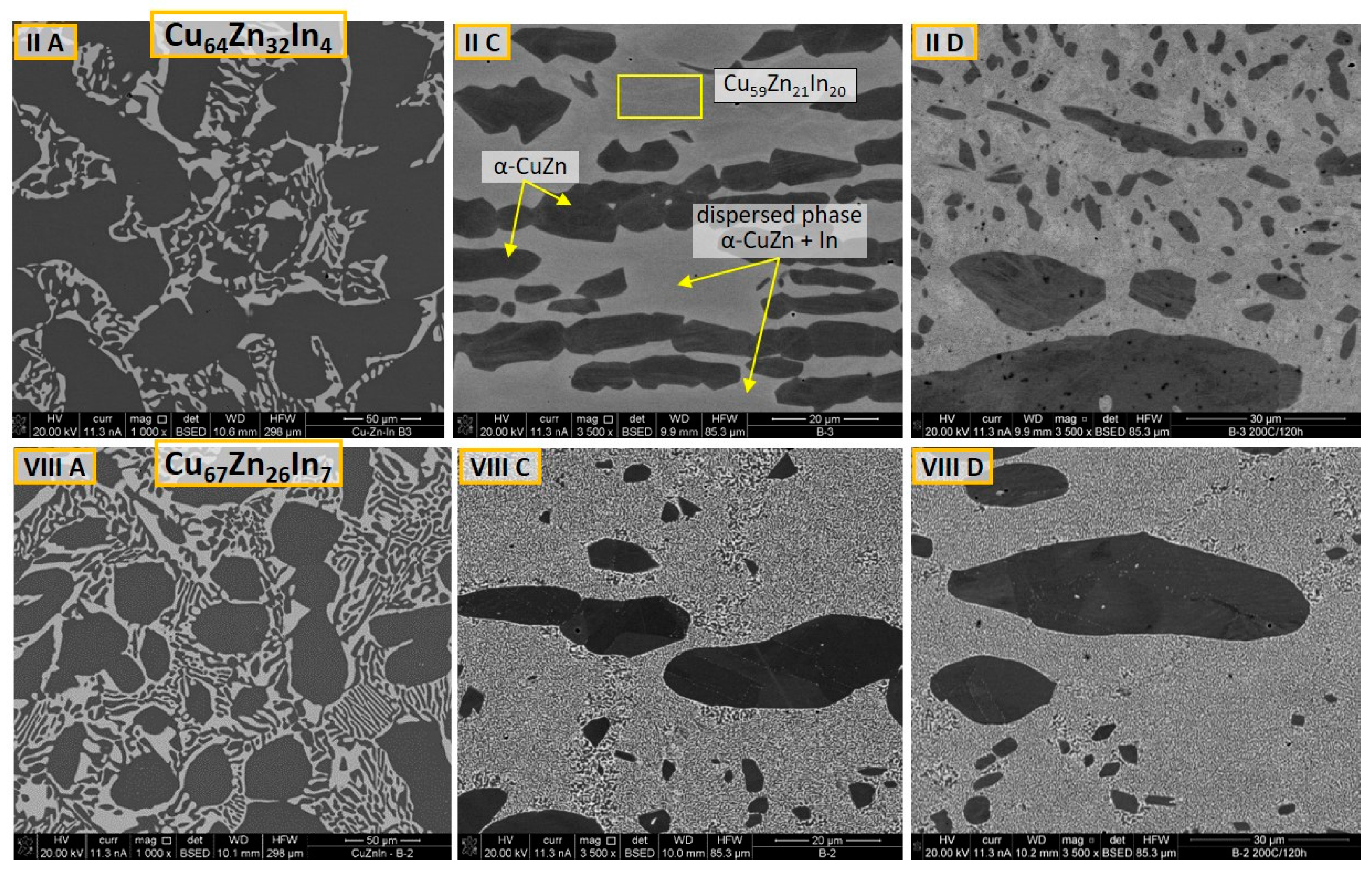
SEM micrographs of the microstructures of alloys in the as-cast state (IIA, IVA, VIIIA, Table 1), at various magnifications, are shown in Figure 3. They are predominantly composed of a dark phase in an elliptical form and a dispersed (minor) light phase characterized by the ternary composition Cu59Zn21In20 (Figure 3a–c). The chemical composition, determined by the EDS method, unequivocally indicates that the dominant phase with a dark contrast was the α-Cu(Zn,In) solid solution with the In content up to 2%. Such a composition corresponds to the equilibrium composition of the solid solution in the CuZn system (Figure 1). According to the CuZnIn ternary cross-section in Figure 2, all investigated alloys should crystallize at temperatures below 927 °C in the α-phase structure. The morphology of the light dispersed in the ternary phase corresponds to the secondary crystallization occurring during cooling below the solidus temperature of the Cu solution in the CuIn system (Figure 1).
Transmission electron microscopy (TEM) was used for the accurate determination of the phase composition and structure, and especially of the Zn content in the In-rich phase. Examples of the TEM microstructures and electron diffraction from the individual phases are shown in Figure 3d–f. For the alloy IIA, it was determined that the dark particles of the α-CuZn(In) phase, surrounded by the In-rich light phase (Figure 3d), correspond to the Cu66Zn34 binary phase, with an fcc structure. The phase revealed the maximum Zn solubility possible in the binary α-CuZn solution. Electron diffraction analysis, performed for the In-rich ternary phase, confirmed the crystallographic structure consistent with the γ-Cu9In4 binary phase (Figure 1). However, the γ-CuIn phase in the binary system is stable only at a high-temperature range, undergoing the peritectoid decomposition during cooling into β-CuIn and η’-Cu9In5 or transforming into the δ-Cu7In3 phase below a temperature of about 650 °C (Figure 1).
The absence of the spots related to the atomic ordering in the respective selected area diffraction patterns (SADPs) suggests cubic, disordered structures in both cases. The new, ternary phase of the structure, similar to the γ-Cu9In4, is further denoted as the γ* phase, related to the CuZnIn system.
In Figure 3e, aside from main spots in SADP, the satellite intensities were observed, suggesting the onset of the decomposition of the α-CuZn(In) phase. On the other hand, the microstructure of the ternary γ*-Cu59Zn21In20 phase shown in Figure 3f revealed distinct local domains, with the straight interfaces suggesting the simultaneous crystallization of the nano-crystals with the slightly different composition or orientation. The stability of the γ* phase, preserving the Cu9In4 phase structure at low temperatures, indicates that Zn addition stabilizes the high-temperature binary CuIn phase. However, in the ternary phase, the proportion of the Cu to In + Zn atoms (1.44) is significantly lower compared to the Cu/In proportions in the Cu9In4 (2.25) or Cu7In3 (2.33) phases. To summarize, it can be assumed that the primary crystallization involves the liquid ternary In-depleted α-phase, while the secondary crystallization concerns the In-rich ternary phase of the complex structure of the γ phase from the CuIn system, easily incorporating relatively large Zn atoms.
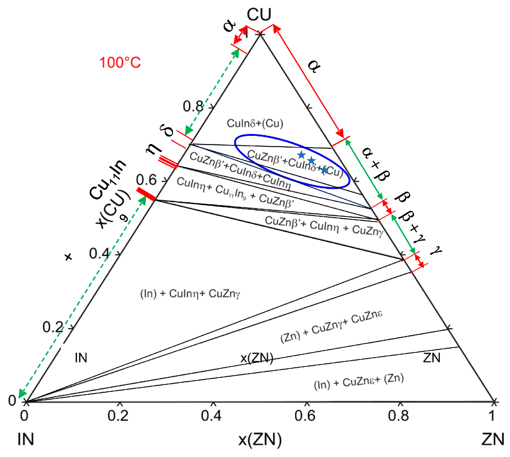
Comparing the obtained results with the modeled phase equilibrium system at 100 °C, presented in Figure 4, it should be noted that the phase composition in the as-cast alloys does not include the phase of the bcc structure, binary or ternary, related to the β-CuZn phase.
The reason for this may be simply topological, resulting from the size of the In atoms and the relatively dense-packed character of the bcc structure. As a consequence, the microstructure of the as–cast alloys suggests the following crystallization path:
L ⇔ L + αCuZn(In) ⇔ αCu(Zn,In) + γ*CuInZn

3.1.2. Hot-Rolled Alloys

Processing the alloys by double hot rolling at about 600 °C to a thickness of less than 1 mm, combined with rapid cooling in water, significantly changed the microstructure, as shown in Figure 5 and Figure 6. In the rolled sheets, the dark particles elongated in the RD, depleted in In, are located in the In-enriched light matrix. In the case of the sheets from the alloy IIC containing 4% In, the EDS analysis revealed that the elongated particles of the dark phase have binary α-CuZn phase composition within a matrix of non-homogenous ternary CuZnIn phase (Figure 5a). Due to the small size of the internal structure, TEM methods were used for the analysis (Figure 5b–d). As a result, the matrix consists of nanocrystalline precipitates of ternary γ*-Cu61Zn18In11 phase of the structure, similar to the γ-Cu9In4 phase but with high Zn content, surrounded by the α- Cu62Zn36In2 solution, with a low In content. Elemental distribution maps (Figure 5d) confirm the homogeneous distribution of Cu in the In-rich phase and the local areas either enriched in In or in Zn. The observed microstructure exhibits a coagulation process of the In-depleted α-CuZn(In) phase (Figure 5a) and the decomposition process of the high-temperature ternary γ* matrix, proceeded by the hot rolling of the alloy and preserved by rapid cooling.
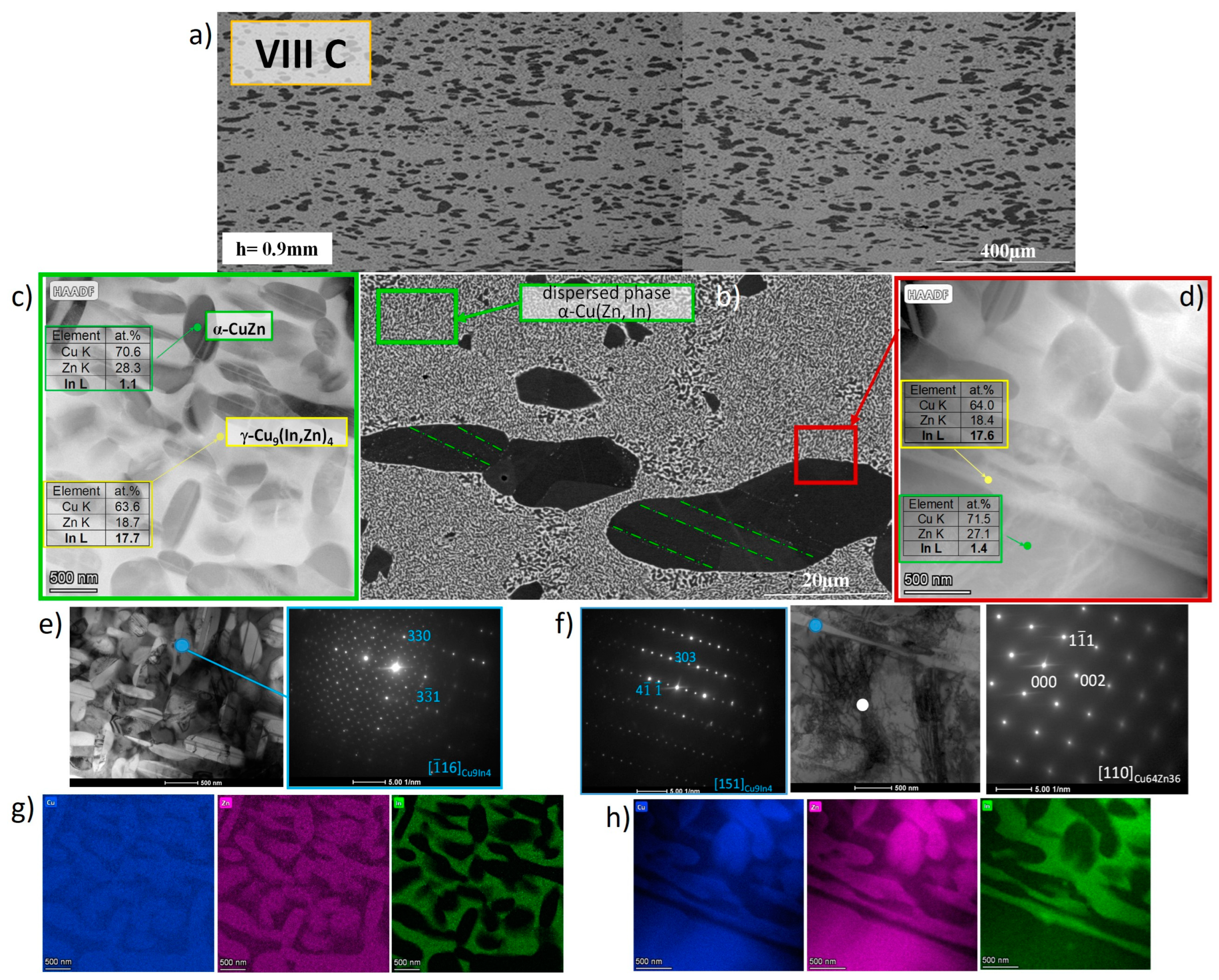
A similar microstructure was observed in the case of alloy VIIIC, with doubled In content, except for a weaker coagulation of the dark α-CuZn(In) particles along the rolling direction (Figure 6). TEM studies revealed that the matrix also consisted of a mixture of two phases, α-CuZn solid solution and ternary γ* CuZnIn phase (Figure 6c–f), both in the form of nanoparticles. EDS-SEM analysis confirmed the average Cu65Zn26In9 matrix composition. SEDPs from the bright particles shown in Figure 6e,f, as well as the elemental distribution in the two types of nanocrystals in the matrix (Figure 6g,h), confirmed that the ternary γ* phase possesses the γ-Cu9In4 phase-type structure and the In-enriched Cu64Zn19In18 composition (Figure 6c). This composition may be also rewritten as Cu8(In,Zn)4.5, with the Cu/In ratio not significantly different from that in the binary γ-Cu9In4 phase. Large, dark particles, with clear twinning (Figure 6b), as well as the nano-particles in the matrix, revealed the solid solution composition of Cu71Zn28(In) (Figure 6c,d). As in the case of the previously presented alloy II C, all results indicated the decomposition of the matrix into a CuZn(In) solid solution and an In-rich ternary γ* phase after hot rolling, preserved by cooling as a metastable state of the structure.

3.1.3. Evolution of Microstructure after Annealing

To investigate the evolution of the phase composition towards equilibrium, samples of the hot-rolled alloys were subjected to the annealing for 120 h at 200 °C. The microstructures of the alloys II D, Cu64Zn32In4 and VIII D Cu67Zn26In7, containing, respectively, the smallest and largest In contents, are compared in Figure 7, namely the as-cast state, after hot rolling, and after annealing. As is seen, the annealing leads to the increased size of the α-phase dark particles, in which some contrast differences suggest some local inhomogeneity (Figure 7(IID)).
The decomposition of the α solid solution is also confirmed in Figure 8, where inside the dark particles of the Cu65Zn31In4 phase, small precipitates of the In-enriched Cu60Zn32In8 phase were identified. Concerning the matrix, in the case of the II D alloy, further decomposition is also visible (Figure 7(IID) and Figure 8b).
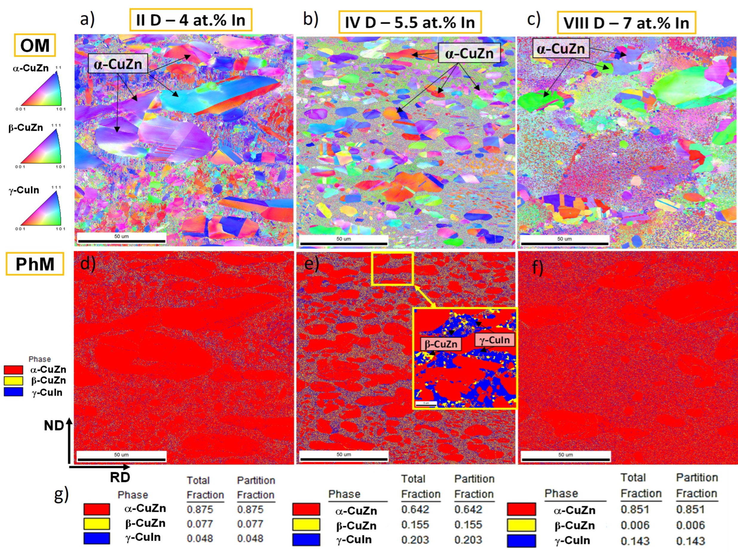
Some additional information concerning the microstructure of the annealed alloys was supplied by the EBSD technique (Figure 9). The orientation maps (OM, Figure 9a–c) indicate that both the size and number of the α phase grains decrease with the increase in In content. Increasing In content from 4% to 5.5 % in the alloys II D and IV D leads to both the refinement and a more homogenous distribution of the particles of the α phase in the matrix. The complex microstructure of the matrix is also clearly visible in Figure 9a,b. In the case of the alloy with 7% atomic indium VIII D (Figure 9c), there is a significantly lower density of α-CuZn particles than in the IV D alloy, but their distribution is very different to that in the alloy II D, which is bimodal with considerably larger and very small particles. The matrix in alloy VIII D exhibits a highly refined structure as well. Phase maps (Figure 9d–f) showed that in alloys II D and IV D with 4% and 7% atomic indium, the proportion of phases γ*-CuZnIn and α-CuZn(In) increases with the amount of indium, while, as a result of the phase composition in the case of alloy IV D including β-CuZn, the precipitation of the β-CuZn phase was simultaneously inhibited. Based on local EBSD maps, a weak texture with typical post-rolling components was found.
The alloy IV D containing 5.5% atomic indium exhibits some unique behavior, as the precipitation of the bcc type phase of the β CuZn structure was also discovered. As previously mentioned, the amount of α-CuZn(In) phase is significantly lower, around 64% by volume. In the matrix identified as the ternary γ* phase, nanocrystals of γ-CuIn and β-CuZn phases were observed in proportions of 20% and 16%, respectively (Figure 10). This result, on one hand, indicates the high stability of the ternary γ*-CuZnIn phase, and on the other hand it confirms its tendency to decompose through the further precipitation of the binary phases α-CuZn, γ-CuIn and β-CuZn through annealing at relatively low temperatures. Due to the bcc structure of the β phase, the particles can act as a strengthening phase for the structure obtained in the rolling process, similar to the natural composites.

3.2. XRD Phase Composition Analysis

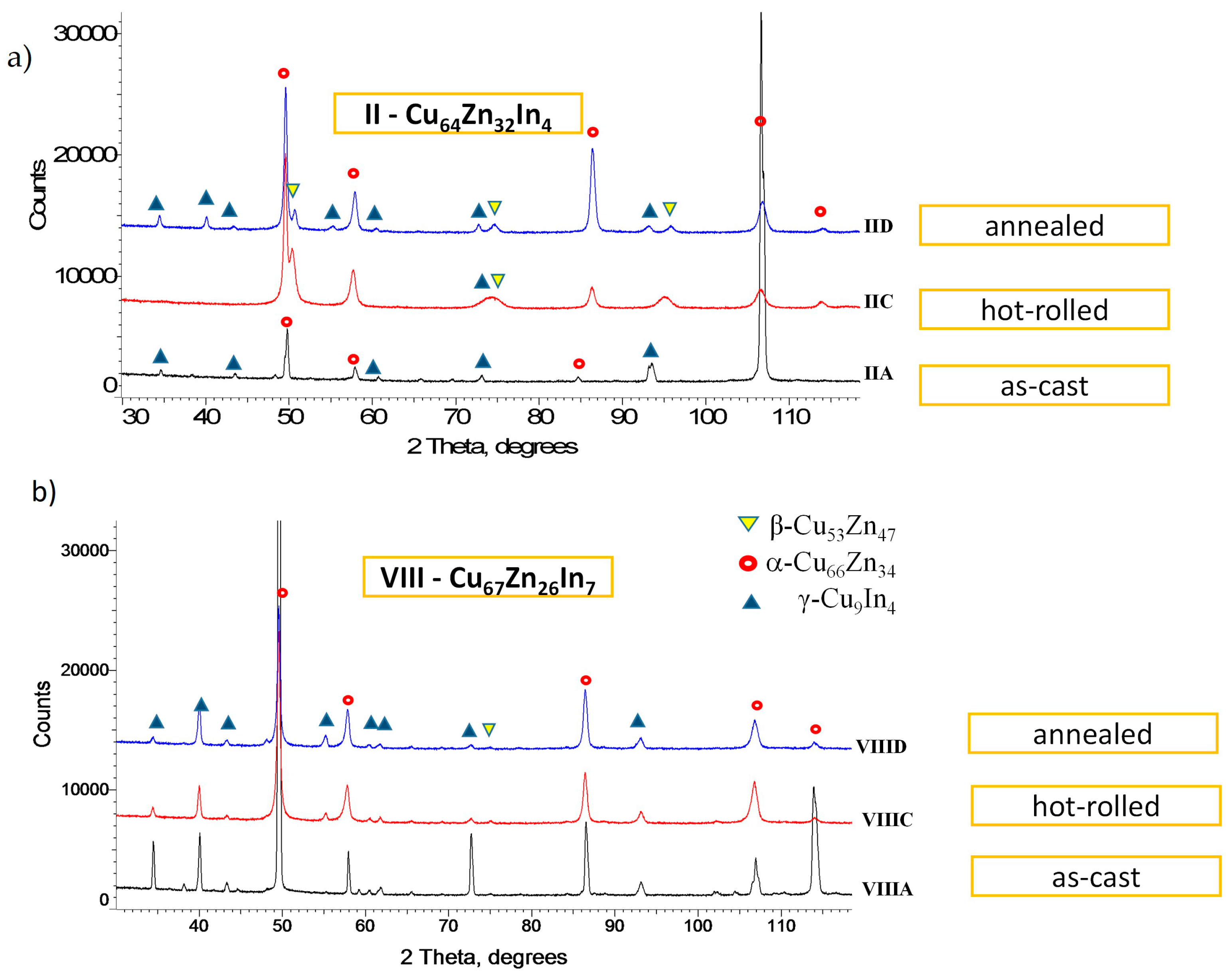
XRD phase composition analysis was conducted for all alloys in three states: as-cast (A), after the second hot rolling (C), and after annealing at 200 °C for 120 h (D). The diffraction patterns, with the identified phase reflections, are presented in Figure 11 and Figure 12. Figure 11 shows the comparison of the diffraction patterns for the alloys containing 4 and 7% In. The diffraction images are arranged according to the sequence of processes conducted, from the as-cast state at the bottom of the figure to the annealed state at the top. By utilizing the crystallographic database PDF4, three phases were identified. The first crystallizes in the copper structure (fcc-type, space group Fm3m), the second in the high-temperature γ-Cu9In4 phase structure (space group P43m), and the third has a bcc-type structure of the β-CuZn phase (space group Im3m). These results reveal that in the cast alloys (II A and VIII B) (Figure 11), the dominant phase is α-CuZn(In) fcc solid solution possessing ductile structure also easy-to-twin (Figure 6b). The other phases are ternary γ*-Cu(In,Zn), with the structure corresponding to the binary γ phase in the CuIn equilibrium system, but characterized by a modified lattice parameter due to the Zn content.
In the alloys subjected to hot rolling and water quenching, the presence of α-CuZn and ternary γ*-CuZnIn phases was observed. A significant broadening of the diffraction lines in the range of 2θ 70–75° for alloy II C, which has the lower In content, is worth highlighting. The presence of the broadened peaks suggests strong refinement of the materials’ structure. An important result is the presence of the phase Cu53Zn47, that is, β-CuZn, not existing in the as-cast alloys. Its largest contribution occurs in the case of the alloy II C, with low In content, in which a γ Cu9In4 phase rich in In was observed as well. In the case of the sheets labeled as C, it was observed that the increase in the content of the ternary γ* phase rich in In was correlated with the increase in In content in alloy composition, as confirmed by the TEM studies presented in Figure 5 and Figure 6. Changes in the phase composition observed after annealing at 200 °C of the hot-rolled alloys revealed the metastable nature of the phases at room temperature. Annealing at 200 °C for 120 h (Figure 12) led to the separation of the broadened peaks (highlighted in red in Figure 12) and proved the evolution of the phase composition to the higher equilibrium state at low temperatures by the precipitation of the nano-particles of the β-CuZn phase in the ternary γ* phase. Average crystallite sizes were estimated to be around 22–42 nm, 23–36 nm, and 19–54 nm for α, γ, and β phases, respectively. However, it was also revealed that increasing In content in the alloys results in a decreased driving force for the decomposition.
Assuming that the total integral intensity of peaks related to the given phase represents its amount in the sample, the phase composition can be analyzed quantitatively. The approximate contribution of individual phases in hot-rolled and annealed sheets II D- VIII D may be determined. In Table 2, the percentage contribution of the total integral intensity of each identified phase is shown, based on the measurements conducted at two orientations of the samples: from the surface (Table 2a) and from the edge (cross-section) (Table 2b).
It should be noted that these are only approximate calculations. In the recorded XRDs, peaks from different phases sometimes overlap and their separation did not allow for precise analysis. However, a rough estimate of the phases’ contribution could be carried out.
Based on the calculations of the volumetric fraction of individual phases, it may be confirmed that for the alloy VIII D, with the highest In content, the β phase content remains almost at the detection limit, while for the sample II D with the lowest In content, a participation of about 5–20% of the β-Cu53Zn47 should be assumed (Table 2). The obtained results confirm the crystallization path proposed on the base of SEM and TEM observations while supplemented with the additional β phase precipitation:
L ⇔ L + αCuZn(In) ⇔ αCuZn(In) + γ*Cu(In,Zn) ⇔ αCuZn(In) + γ*Cu(In,Zn) + βCuZn

3.3. Modeling of the Structures of γ* Cu(In,Zn)

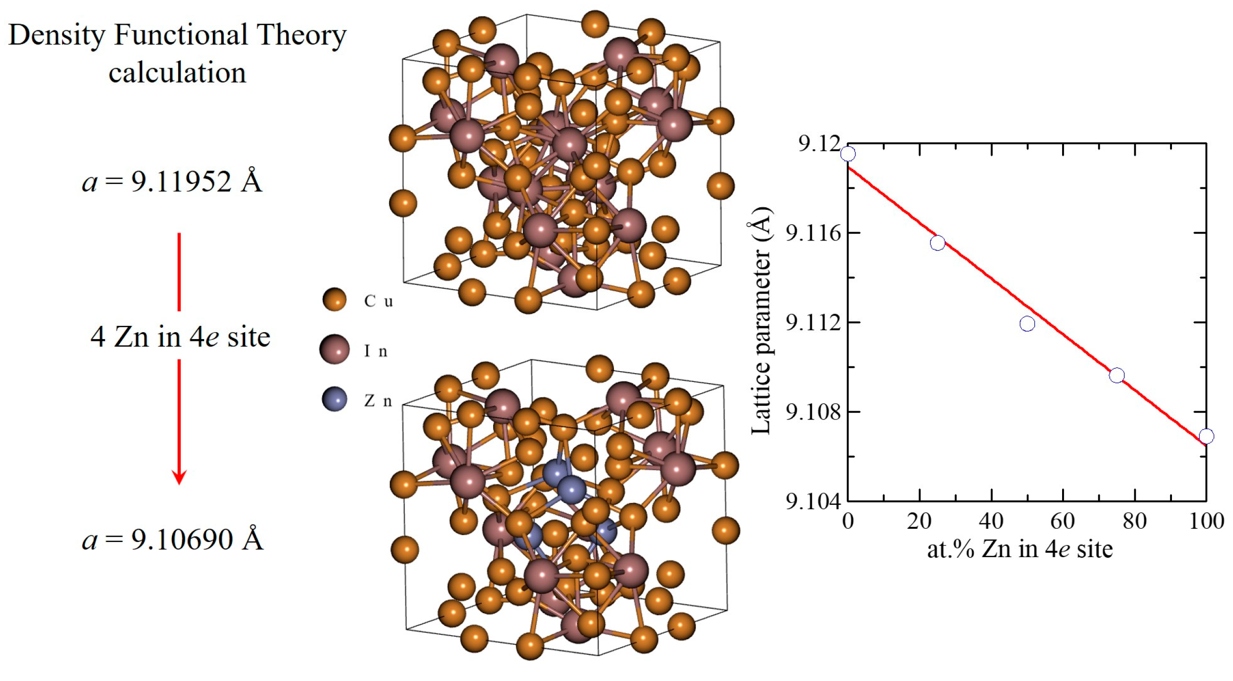
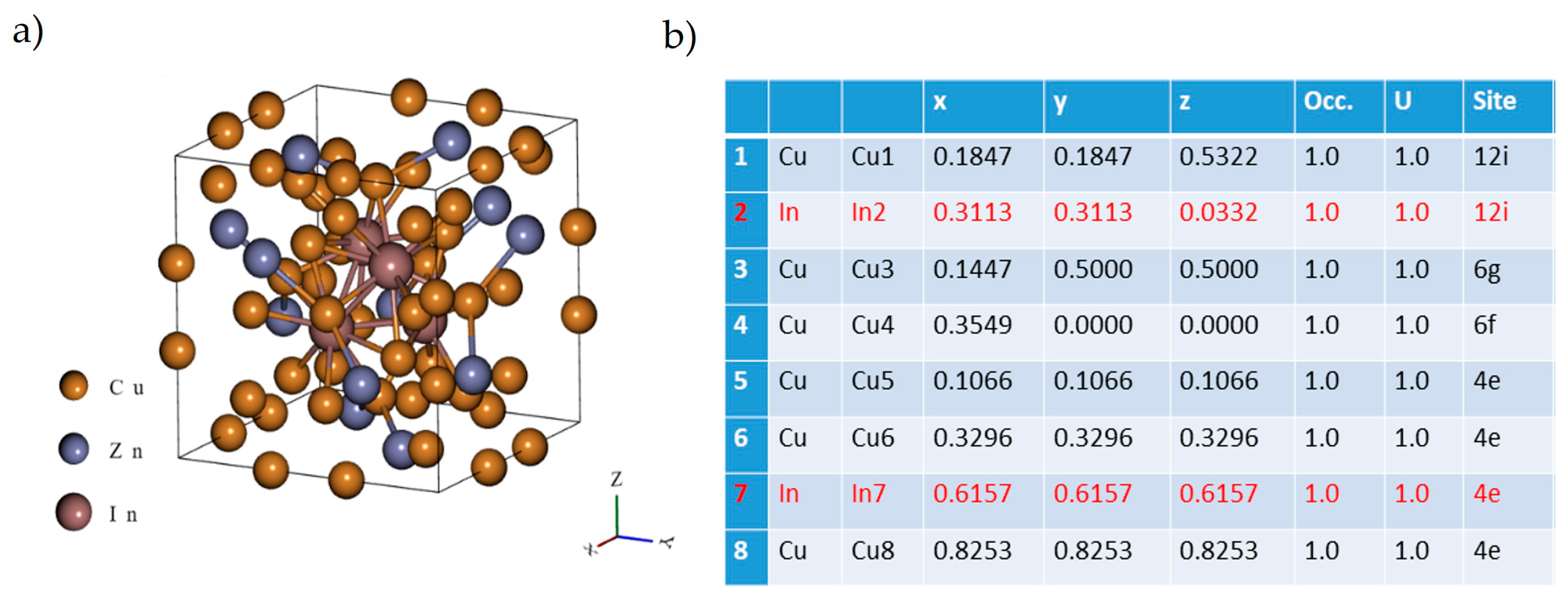
As a result of the X-ray diffraction analysis, the values of the lattice constants of the identified phases were determined using the Nelson–Riley extrapolation method (Table 3). The obtained results indicate that the lattice parameter of the α phase remains relatively unchanged, while for the β and γ* phases a reduction in the lattice constancies in the range of 0.2–0.5% was observed. The reason for these differences in the lattice parameters is the presence of the strange atoms replacing the host atoms in the structures. There is no solubility between In and Zn [5], but the identified ternary γ* phase proves that Zn atoms can replace In atoms in the Cu9In4 structure, in which there are two symmetrically independent positions for the atoms of In. To confirm this hypothesis, work was undertaken to optimize the geometry of the unit cell of γ-Cu9In4 phase containing substitutive Zn atoms in place of In. Density functional theory (DFT) was applied. The analyzed cases included only the simplest scenarios: the substitution of Zn atoms sequentially at the 4e positions (1, 2, 3, and 4 atoms), the substitution of Zn atoms at all 12i positions (12 atoms) and the replacement of all In atoms by Zn atoms (Figure 13 and Figure 14a).
For the Cu9In4 structure, the unit cell parameter a [Å] = 9.11952 was obtained. The relative deviation from the experimental value reported in the 2023 crystallographic database PDF4+ (a = 9.097 Å) is approximately 0.25%. In the γ-Cu9In4 phase, replacing four In atoms with a large 155 pm radius at the 4e positions by four Zn atoms with a smaller atomic radius of 135 pm leads to the reduction in the value of the unit cell parameter to 9.10690 [Å] (Figure 13). The relative decrease in the Cu9In4 unit cell parameter value due to the Zn atoms replacing all In atoms (In7) at the 4e position is approximately 0.14% (Figure 14b). In the experiments conducted on the II D, IV D and VIII D samples, a relative change in the unit cell parameter value of γ* Cu9(In, Zn)4 was observed from 0.2 to 0.5% (Table 3). This suggests that other indium atomic positions, such as the In2 (Figure 14), may also be susceptible to Zn substitution. The obtained results indicate that the ternary phase of the type γ* Cu9(In, Zn)4, with modified cell constancies, can crystallize in the high temperature liquid solution range.

3.4. Thermomechanical Analysis of Hot-Rolled Alloys

To determine the feasibility of forming elements from the examined CuZnIn alloy sheets, phase transition ranges and deformability were investigated using thermomechanical analysis (TMA). The TMA method, due to its ability to monitor changes under stress and temperature, allows for the thermomechanical analysis of the material, indicating the dimensional changes of the tested material. Recording these changes enables the determination of temperature ranges in which the material remains stable (under specific stress conditions) and the identification of characteristic temperatures for the phase transitions. Thermomechanical studies were conducted in the tensile mode, under the load of 2.5 N, recording relative elongation at temperatures up to 650 °C, increased by 5 K/min. Samples for the study were in the form of a rectangular prism with the height of 20 mm and the cross-sectional area of approximately 0.6–0.9 mm2. Figure 15a depicts the dependence of the changes in relative elongation dL/L0 as a function of temperature T (dL/L0 = f(T)) for the samples II C, IV C and VIII C of the alloys after the second hot rolling. Three ranges of elongation could be identified. The first range occurs in the RT—200 °C temperature range and is characterized by the linear increase in the relative elongation, and results from the thermal expansion of the alloy.
The second, most interesting range covers the temperature range from 200 to 400 °C, where the deviation from the linear relative elongation was observed. This phenomenon is associated with the weak phase transformations in the material under study (Figure 15b) related with the processes of In diffusion towards α-CuZn binary solid solution. The changes in ΔL are particularly evident in the derivative curve dL/dt with respect to time. To confirm these processes, the sheets underwent three heating cycles in the DSC experiment. The presence of the endothermic effects in the range of 200–400 °C was observed (Figure 15c).
An analysis of the obtained results and the increase in indium solubility in copper in the CuIn system (Figure 1) confirm the diffusive character of the processes in this temperature range. Above 400 °C, in the third range, the enhanced material elongation was observed, indicating the complete loss of mechanical stability of the samples, which may be related to the appearance of the structural phase transition. These deformations correlate with endothermic peaks in the DSC curves (Figure 15c). The character of this transition in the ternary system needs, however, further investigation.

4. Summary

The results of the microstructure analysis and phase composition of the as-cast alloys and sheets produced by hot rolling at 600 °C revealed a phase composition consisting of the combination of massive particles of α-CuZn solid solution with a small addition of In and a ternary γ* CuZnIn phase, possessing the structure of the γ-CuIn phase but modified by the Zn atoms substitution. The γ* phase remains stable at low temperatures, in spite of its clearly metastable character, while the γ-CuIn phase in the binary system decomposes by peritectoidal decomposition at about 616 °C (Figure 1). No other phases like β or η CuIn were found. The stability of the γ* phase at low temperatures is thought to be related to the role of Zn atoms in stabilizing the modified structure. The hot rolling led to the dispersion of the phase particles, forming a structure similar to the artificial composite, composed of the elongated Cu(Zn) solid solution particles in the γ* matrix.
An analysis of the phase structure after long-time low-temperature annealing revealed the further phase separation processes of the α and β phases of the CuZn composition in the γ* matrix. The separation of the β and α phases occurs in the form of micro- and nanoscale particles, making the γ* matrix a complex phase microstructure. The results of the thermomechanical analysis indicate a change in the rheological parameters during slow heating, especially in the range of 200–400 °C, consistent with the presence of increased diffusion and a slow precipitation; however, the alloys reveal a lack of the mechanical stability at about 600 °C. The results revealed the large range of temperature stability of the ternary γ* Cu(In,Zn) phase possessing the modified structure of the binary γ-CuIn phase. However, the γ*phase remains metastable, prone to further slow decomposition by the precipitation of the binary Cu(Zn) solid solution and the β-CuZn phase.

5. Conclusions

  • A ternary phase with an approximate composition of Cu8(In,Zn)4,5 and a structure analogous to the high-temperature γ-Cu9In4 phase remains stable at low temperatures. This behavior results from the absence of a peritectoidal decomposition and the absence of the β-CuIn phase,
  • A modification of the structure of the γ-Cu9In4 phase has been identified, characterized by a reduced unit cell and altered electronic structure, where zinc atoms replace indium atoms in a one-to-one ratio, and this phase has been labeled as γ* Cu(In,Zn),
  • The α-CuZn solution phase, with the minor additions of indium (1–2% at.), was the primary phase crystallized during casting and remained stable at low temperatures.
  • The hot-rolling process preserves the phase composition and leads to the formation of a composite-like structure, with a matrix composition of γ* and large ellipsoidal α-CuZn solution particles,
  • On a microscale, the γ* matrix exhibits a specific structure resulting from the segregation processes and is composed of micrometer-sized α-CuZn(In) solution particles and nano-sized β-CuZn phase precipitates.
  • Low-temperature annealing intensifies the decomposition process of the γ* matrix through the precipitation of binary α and β phases.

Author Contributions

Conceptualization, T.C. and A.S.; methodology, T.C. and A.S.; software, G.G. and Z.S.; validation, T.C.; formal analysis, T.C. and A.S.; investigation, T.C., A.S., G.G., A.W., A.G., Z.S. and M.K.; writing—original draft preparation, T.C. and A.S.; writing—review and editing, T.C. and A.S.; visualization, T.C., A.S., G.G., A.W., A.G. and Z.S.; supervision, T.C. and A.S. All authors have read and agreed to the published version of the manuscript.

Funding

This research was funded as statutory project of IMMS PAS in Krakow in the year 2023 [No. Z-6/2023].

Institutional Review Board Statement

Not applicable.

Informed Consent Statement

Not applicable.

Data Availability Statement

The original contributions presented in the study are included in the article, further inquiries can be directed to the corresponding authors.

Acknowledgments

The work was realized as statutory project of IMMS PAS in Krakow in the year 2023 in the Accredited Laboratories of IMIM PAS. The authors thank the Polish High Efficiency Computing Centre PLGrid (Centrum HPC: [“ACK Cyfronet AGH”]) for the support on the Ares Supercomputer under the computational grant no. PLG/2023/016473.

Conflicts of Interest

The authors declare no conflicts of interest.

References

  1. Miodownik, A.P. Cu-Zn Phase Diagram. In Binary Alloy Phase Diagrams; ASM International: Detroit, MI, USA, 1989; p. 1509. [Google Scholar]
  2. Kowalski, M.; Spencer, P.J. Thermodynamic Reevaluation of the Cu-Zn System. J. Phase Equilibria 1993, 14, 432–438. [Google Scholar] [CrossRef]
  3. Subramanian, P.R.; Laughlin, D.E. Cu-In Phase Diagram. In Binary Alloy Phase Diagrams; ASM International: Detroit, MI, USA, 1989; p. 1425. [Google Scholar]
  4. Liu, H.S.; Liu, X.J.; Cui, Y.; Wang, C.P.; Ohnuma, I.; Kainuma, R.; Jin, Z.P.; Ishida, K. Thermodynamic Assessment of the Cu-In Binary System. J. Phase Equilibria 2002, 23, 409–415. [Google Scholar] [CrossRef]
  5. Dutkiewicz, J.; Zakulski, W. In-Zn Phase Diagram. In Binary Alloy Phase Diagrams; ASM International: Detroit, MI, USA, 1984; p. 2318. [Google Scholar]
  6. Knott, S.; Chen, C.-J.; Gehringer, F.; Mikula, A. Thermodynamic properties of liquid Cu-In-Zn alloys. Inter. Mat. Res. 2006, 97, 1102–1107. [Google Scholar] [CrossRef]
  7. Vassilev, V.P.; Lysenko, V.A. Thermodynamic evaluation of the Cu-In-Zn system. J. Alloys Compd. 2016, 681, 606–612. [Google Scholar] [CrossRef]
  8. Kim, B.; Lee, C.W.; Lee, D.; Kang, N. Effect of Sb Addition on Bi-26Ag-01Cu Solders for High-Temperature Applications. J. Alloys Compd. 2014, 592, 207–212. [Google Scholar] [CrossRef]
  9. Lee, J.E.; Kim, K.S.; Suganuma, K.; Takenaka, J.; Hagio, K. Interfacial Properties of Zn-Sn Alloys as High Temperature Lead-Free Solder on Cu Substrate. Mater. Trans. 2005, 46, 2413–2418. [Google Scholar] [CrossRef]
  10. Lee, J.E.; Kim, K.S.; Suganuma, K.; Inoue, M.; Izuta, G. Thermal properties and phase Stability of Zn-Sn and Zn-In Alloys as High Temperature Lead-Free Solder. Mater. Trans. 2007, 48, 584–593. [Google Scholar] [CrossRef]
  11. Dinsdale, A.; Watson, A.; Kroupa, A.; Vrestal, J.; Vizdal, J. Atlas of Phase Diagrams for Lead-Free Soldering; COST 531 Lead Free Solders; COST Office: Prague, Czech Republic, 2008; Volume 1, pp. 82, 107. [Google Scholar]
  12. Li, L.; Song, K.; Zhou, Y.W.; Liu, Q.; Wang, K.; Bao, Y.; Zhao, B.; Jian, X.D.; Ji, C.L.; Qian, P.; et al. The thermodynamic properties of disorder CuZn solid solution and nonstoichiometric CuZn alloy: Pseudo-atomic lattice inversion potential method. J. Solid. State Chem. 2020, 289, 121488. [Google Scholar] [CrossRef]
  13. Hong, H.L.; Wang, Q.; Dong, C.; Liaw, P.K. Understanding the Cu-Zn brass alloys using a short-range-order cluster model: Significance of specific compositions of industrial alloys. Sci. Rep. 2014, 4, 7065. [Google Scholar] [CrossRef] [PubMed]
  14. Takamatsu, Y.; Minho, O.M.; Kajihara, M. Kinetics of Solid-State Reactive Diffusion in the Cu/Zn System. Mater. Trans. 2017, 58, 16–22. [Google Scholar] [CrossRef]
  15. Liu, K.; Ding, W.; Tao, X.; Chen, H.; Ouyang, Y.; Du, Y. Diffusional behaviors and mechanical properties of CueZn system. J. Alloys Compd. 2020, 812, 152141. [Google Scholar] [CrossRef]
  16. Ortner, N.; Lund, H.; Armbruster, U.; Wohlrab, S.; Kondratenko, E.V. Factors affecting primary and secondary pathways in CO2 hydrogenation to methanol over CuZnIn/MZrOx (La, Ti or Y). Catal. Today 2022, 387, 47–53. [Google Scholar] [CrossRef]
  17. Czeppe, T.; Sypien, A.; Wierzbicka-Miernik, A.; Garzel, G.; Kopyto, M. Phase Formation and Diffusivity in the Ternary Cu-Zn-In System. J. Mater. Eng. Perform. 2022, 31, 6962–6969. [Google Scholar] [CrossRef]
Figure 1. CuIn binary phase diagram [4].
Crystals 14 00669 g001
Figure 2. Hypothetical solidus projection for the CuZnIn system with the isotherm and phase field boundaries at crystallization temperatures (PANDAT). The investigated composition marked as stars with expected solidus temperatures of alloys.
Crystals 14 00669 g002
Figure 3. Microstructure of the as-cast alloys: (a) IIA; (b) IVA; (c) VIII—SEM on the cross-section; (d) IIC; (e,f) VIIIA—TEM microstructure and SADP from the dispersed phase. The arrows and boxes indicate the relationship between investigated areas.
Crystals 14 00669 g003
Figure 4. Calculated phase equilibrium diagram for the CuZnIn system at 100 °C, showing phase boundaries and the expected phase composition (PANDAT). The composition of investigated alloys marked as stars.
Crystals 14 00669 g004
Figure 5. Microstructure of the alloy IIC after hot rolling at 600 °C, observed with SEM, TEM and SADP from dispersed phases: (a) microstructure overview (SEM); (b) detailed view of the nanocrystalline matrix structure (HAADF); (c) high-resolution image of the phase boundaries; (d) elemental distribution maps; (e) SADP from the matrix. The arrows and boxes indicate the relationship between investigated areas.
Crystals 14 00669 g005
Figure 6. Microstructure and phase composition of the Cu67Zn26In7 alloy (VIII C) after two stages of rolling at 600 °C: (a,b) SEM; (c,d) TEM—HAADF; (e,f) BF + electron diffraction; (g,h) TEM elemental distribution map. The arrows and boxes indicate the relationship between investigated areas.
Crystals 14 00669 g006
Figure 7. SEM microstructures of Cu64Zn32In4 and Cu67Zn26In7 alloys in as-cast state (IIA, VIIIA), after rolling (IIC, VIIIC), and after annealing at 200 °C for 120 hours (IID, VIIID). The arrows and boxes indicate the respective areas examined.
Crystals 14 00669 g007
Figure 8. SEM microstructures of Cu64Zn32In4 alloy (II D) after annealing at 200 °C for 120 h (a), large magnification of the area in the yellow box (b).
Crystals 14 00669 g008
Figure 9. Orientation maps (OM); (a) II D; (b) IV D; (c) VIII D and phase maps (PhM) (d) II D; (e) IV D, The yellow box shows the magnification of the area in the insert; (f) VIII D; (g) comparison of the total fraction of identified phases of the investigated alloys after annealing at 200 °C for 120 h. EBSD method.
Crystals 14 00669 g009
Figure 10. Orientation maps (OM) for alloy IV D after annealing at 200 °C for 120 h (a); large magnification of the area in the green box in (a): orientation maps (OM) (b) and phase map (PhM) (c). EBSD method.
Crystals 14 00669 g010
Figure 11. Comparison of XRD diffraction curves in the as-cast state (IIA, VIIIA), after hot rolling (IIC, VIIIC) and annealing (IID, VIIID) for alloys: (a) II-Cu64Zn32In4; (b) VIII-Cu67Zn26In7.
Crystals 14 00669 g011
Figure 12. Comparison of XRD diffraction curves after annealing at 120 °C for 120 h for alloys: IID-Cu64Zn32In4; IVD-Cu66Zn26In5; VIIID-Cu67Zn26In7. The red circles denote the presence of β-phase.
Crystals 14 00669 g012
Figure 13. DFT calculation result for the Cu9(In, Zn)4 structure with zinc atoms substituting indium atoms at the 4e positions. On the right side is a graph showing the dependence of the Cu9In4 unit cell parameter value on the occupancy of the 4e positions.
Crystals 14 00669 g013
Figure 14. Proposed arrangements of In2 atoms in positions completely occupied by Zn atoms (12i positions): unit cell schematic (a); The table showing the atomic positional distribution data in the cell with the substituted Indium positions highlighted in red (b).
Crystals 14 00669 g014
Figure 15. Thermomechanical analysis (TMA) curves depicting the relative elongation recorded under a constant load of 2.5 N as a function of temperature, with a heating rate of 5 K/min for rolled sheets IIC, IVC, and VIIIC (a); magnification of the II range (b); comparison of the DSC curves for the alloy II C obtained in three heating cycles, heating rate 20°/min (c).
Crystals 14 00669 g015
Table 1. Composition of the studied alloys and designations of the samples after processing.
Composition of the Alloy [%at.]Symbol of the Sample
As-CastTwo-Step Hot Rolling, up to 0.4–0.7 mm in ThicknessAnnealed at
200 °C/120 h,
Water Cooled
Cu64Zn32In4II AII CII D
Cu65Zn29In5.5IV AIV CIV D
Cu67Zn26In7VIII AVIII CVIII D
Table 2. Percentage contribution of the total integral intensity of each of the identified phase peaks calculated on the base of XRD measurements for the II D, IV D and VIII D annealed sheets of the alloys.
(a) XRD Peaks Integration, from the Surface
Sample% α—Cu66Zn34
(FCC)
% γ—Cu9In4
(FCC)
% β—Cu53Zn47
(BCC)
Total
II D—4 at.% In89.45.45.2100
IV D—5.5 at.% In59.536.34.2100
VIII D—7 at.% In60.637.61.8100
(b) XRD Peaks Integration, from Cross-section
Sample% α—Cu66Zn34
(FCC)
% γ—Cu9In4
(FCC)
% β—Cu53Zn47
(BCC)
Total
II D—4 at.% In79.31.119.6100
IV D—5.5 at.% In67.621.810.6100
VIII D—7 at.% In84.813.91.2100
Table 3. Lattice parameter values of the identified phases in the IID, IVD and VIIID sheet samples determined using the Nelson–Riley linear extrapolation method from edge measurement, compared to the lattice parameter values from the PDF4+ database.
Binary Phases
(PDF4+ Data Base)
Ternary Phases Experimental Results∆a/a [%]
Relative Difference Binary/ Ternary Phases
PhaseSpace GroupaPhasea
Cu64Zn32In4II
α—Cu66Zn34 F m 3 ¯ m 3.697α—Cu(Zn,In)3.694(1)0.08
β—Cu53Zn47 I m 3 ¯ m 2.955β—(Cu,Zn,In)2.951(5)0.1
Cu65.5Zn29In5.5IV
α—Cu66Zn34 F m 3 ¯ m 3.697α—Cu(Zn,In)3.695(2)0.05
β—Cu53Zn47 I m 3 ¯ m 2.955β—(Cu,Zn,In)2.941(6)0.5
γ—Cu9In4 P 4 ¯ 3 m 9.097γ—Cu9(In,Zn)49.079(8)0.2
Cu67Zn26In7VIII
α—Cu66Zn34 F m 3 ¯ m 3.697α—Cu(Zn,In)3.693(1)0.1
γ—Cu9In4 P 4 ¯ 3 m 9.097γ—Cu9(In,Zn)49.055(4)0.5
Disclaimer/Publisher’s Note: The statements, opinions and data contained in all publications are solely those of the individual author(s) and contributor(s) and not of MDPI and/or the editor(s). MDPI and/or the editor(s) disclaim responsibility for any injury to people or property resulting from any ideas, methods, instructions or products referred to in the content.