Abstract
As high-strength aluminum alloys present several processability issues with additive manufacturing (AM), Scalmalloy®, an Al-Mg-Sc-Zr-based alloy, has been developed. This alloy is age-hardenable, allowing it to precipitate out a strengthening precipitate phase, Al3(Sc,Zr). The manufacturer recommends a single-stage aging treatment at 325 °C for 4 h; however, the majority of the literature studies utilize a powder bed processing known as selective laser melting (SLM) over powder-fed processing directed energy deposition (DED). This study addresses the lack of information on heat treatments for DED fabrication by exploring the application of artificial aging temperatures of 300–400 °C for 2, 4, and 6 h to: 1. determine the impact on the microstructural evolution and mechanical performance and 2. determine whether the recommended treatment for Scalmalloy® is appropriate for DED fabrication. Tensile testing determined that low-temperature treatments exhibited no visible dependence on time (2–6 h); however, time becomes influential at higher temperatures starting at 350 °C. The temperature plays a considerable role in the mechanical and microstructural behaviors of DED Scalmalloy®. The highest tensile strength was noted at 300 °C (384 MPa, 21.6% increase), but all heat-treated cases resulted in an improvement over the as-built case. This investigation established that increasing the treatment temperature resulted in a decreasing trend for the tensile strength that held over time. Elongation at 2 h displayed a near parabolic trend that peaks at 350 °C (20%) and falls with higher temperatures. At the 4 h treatment, a slight decreasing trend was noticed for elongation. No visible change was observed for elongation at 6 h, with elongation values remaining fairly consistent. The microstructural evolution, including micron-sized and nano-sized Al3(Sc,Zr) and grain size, was examined, and coarsening effects were noted with the increase in the temperature. It is recommended that treatment be conducted at 300 °C to achieve the precipitation of the strengthening Al3(Sc,Zr) phase while minimizing coarsening.
1. Introduction
Aluminum and its alloys have received significant attention due to their application in fields that highly prize their high strength-to-weight ratio [1]. Despite this promising feature, making these alloys highly desired to use with AM, aluminum alloys exhibit high thermal conductivity [1,2,3], poor laser absorptivity [1,2,3,4], and a high tendency for oxide formation [1,2,3,4]. Due to these characteristics, only a select number of aluminum alloys are compatible with AM. The desired high-strength aluminum alloys do not fall into this category due to their tendency to exhibit defects, such as porosity, lack of fusion, elemental loss due to the vaporization of low boiling point elements, and cracking [1,2,3]. These defects have been shown to have a negative impact on mechanical behavior, producing components with considerably lower mechanical properties when compared to AM-compatible alloys and high-strength alloys fabricated using conventional processing methods [3,5].
To combat the processability issues of high-strength aluminum alloys with AM, novel alloy compositions are being developed. Scalmalloy®, a new Al-Mg-Sc-Zr-based alloy designed for AM, has garnered considerable attention for its improved processability, unique microstructural features, and ability to demonstrate mechanical properties on par or superior to its conventionally processed counterparts. The microstructure of powder bed AM-fabricated Scalmalloy® components has been shown on several occasions to be a bimodal distribution in which fine-grained and coarse-grained regions exist [6,7,8,9,10]. Spierings et al. hypothesized that the fine-grained region was the direct result of a large number of seed crystals acting as nucleation sites around the boundary of the melt pool [7]. Comparatively, the coarse-grained region was connected to the smaller number of seed crystals coupled with a high-temperature gradient, resulting in larger, coarse columnar grains [7]. Kuo et al. determined that the lack of Al3Sc precipitates in the as-built microstructure led to zones in which no precipitation strengthening occurred [11].
For Scalmalloy®, the manufacturer recommends a single-step aging treatment for powder bed-fabricated components at 325 °C for 4 h [12]. Kuo et al. determined that the non-homogenous microstructure led to lower yield strengths for the as-built condition; however, the subsequent heat treatment improved the mechanical behavior through the precipitation of a strengthening Al3Sc phase [11]. Some investigations have explored a range of times and temperatures to determine the optimal heat treatment characteristics of Scalmalloy® and other Al-Mg-Sc-based alloys [8,13,14]. Spierings et al. found the best tensile strength by aging at temperatures in the range of 325–350 °C for 4–10 h [8]. In another study, Spierings et al. noted that temperatures in excess of 400 °C for a hold time of at least four hours resulted in a decrease in hardness [7]. The lower hardness values obtained were caused by Ostwald ripening from too large Al3(Sc,Zr) precipitates where it became more favorable to introduce a dislocation rather than increase the strain around the particle [7]. Baig et al. explored heat treatments at 325, 350, and 375 °C for various times up to 24 h and noted that the highest hardness overall, 160 ± 8 HV, occurred at 325 °C at 4 h [13]. While single-stage aging for the post-processing of Scalmalloy® has been well explored for powder bed processing, little to no literature exists that explores the heat treatment of powder-fed Scalmalloy® components.
Powder bed and powder-fed processes fall into the metal additive manufacturing category but have distinct differences. Table 1 details some of the characteristics of the powder bed process, selective laser melting (SLM), and the powder-fed process, directed energy deposition (DED). Of note is the difference between the cooling rates, which can dramatically impact the final microstructure [15]. Furthermore, studies have noted the greater tendency towards defect formation using DED fabrication methods when processing Scalmalloy®, making the process difficult to use effectively [16].

Table 1.
SLM vs. DED processing features.
Despite the advantages of SLM, DED cannot be written off as an inferior process. DED has features that are not possible with SLM and presents several avenues for advancement and investigation. For example, DED has the capability for repair applications, in situ composition blending using multiple powder feeders, and functionally graded materials [19,21,22,25]. Furthermore, the current state of the literature has a distinct lack of heat treatment studies for DED. Most of the literature has thoroughly explored the heat treatment of SLM compositions; however, as noted above, SLM and DED are distinctly different processes and produce markedly different starting microstructures. As such, it can be stated that the microstructures, when processed using the same heat treatment, would result in different ending microstructures and diverging mechanical properties. These possibilities highlight the need for more investigation into DED processing and the post-processing of Scalmalloy® to determine avenues that can be pursued to enhance mechanical performance while maintaining the unique capabilities inherent to DED.
This investigation focuses on fabricating Scalmalloy® components via the powder-fed process DED and subsequent post-processing to enhance their mechanical behavior relative to the as-built condition and the conventionally processed high-strength 7XXX series Al-Zn alloys. As-built and heat-treated Scalmalloy® components were examined to determine their microstructural and mechanical characteristics and provide a recommendation for the heat treatment of DED Scalmalloy®. Furthermore, many DED studies use Al-Mg-Sc-Zr alloy compositions not characterized as Scalmalloy®. This study can be applied to similar compositions and act as a starting point for optimization studies for these other alloys.
2. Materials and Methods
2.1. AM Processing
Scalmalloy® was obtained from Toyal America, Inc. (Lockport, IL, USA). Figure 1a shows the morphology of the sourced Scalmalloy®. The powder exhibits high sphericity with little to no agglomerates and satellites. The powder distribution is shown in Figure 1b. Scalmalloy® components were fabricated using an in-house, custom-designed directed energy deposition (DED) system in a shielded argon environment flowing at 1 L/min, as depicted in Figure 2a. The deposition parameters for this experiment are 1625 W power, 15 mm/s scan speed, and 2.25 g/min powder feed rate. The deposited coupons were 25 mm × 25 mm × 6 mm, as presented in Figure 2b. The parameter optimization to yield the chosen deposition parameters is detailed in Boillat-Newport et al. [28]. The resulting deposits from the optimized parameters exhibited minimal defects, such as porosity and cracking. Good adhesion was noted between the deposit and substrate. The Archimedes density performed on the deposits determined that the optimized properties produced near fully dense components.
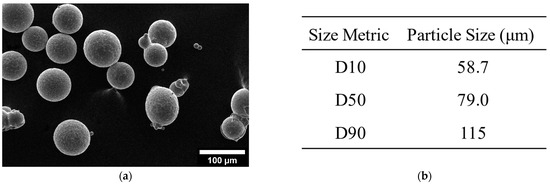
Figure 1.
(a) Scalmalloy® powder sourced from Toyal America, Inc. Reprinted with permission from Ref. [28], 2024, MDPI. (b) Particle size distribution of the Scalmalloy® feedstock material.
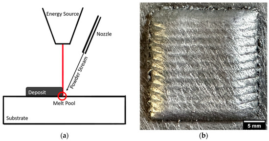
Figure 2.
(a) DED process schematic. Reprinted with permission from Ref. [29], 2021, MDPI. (b) DED-fabricated Scalmalloy® coupon. Reprinted with permission from Ref. [28], 2024, MDPI.
2.2. Heat Treatment
Scalmalloy® deposits were heat-treated across a range of times and temperatures to identify a direct aging treatment time and temperature that would work for DED components. Deposits were heat-treated at 300, 325, 350, 375, and 400 °C for 2, 4, and 6 h. For each treatment, a ramp from 25 °C (room temperature) to the target temperature occurred at 10 °C per minute. After the specified hold for each case, the deposits were air-cooled to room temperature.
2.3. Microstructural and Mechanical Characterization
Microscopy specimens were polished to 0.05 microns using a colloidal alumina suspension. The microstructure was characterized using a Thermo Fisher Scientific, Inc. (TFS) (Waltham, MA, USA) PRISMA scanning electron microscope (SEM) and TFS HYDRA for electron microscopy imaging and TFS, previously FEI, Helios NanoLab 600 with an Oxford Aztec detector for energy dispersive spectroscopy (EDS). For each scope, the manufacturer’s recommended working distance was utilized (10 mm for TFS PRISMA, 4 mm for TFS HYDRA, and 5 mm for TFS Helios NanoLab 600). Electron backscatter diffraction (EBSD) was performed by JH Analytical using a Thermo Fisher Scientific (Brno, Czech Republic) Apreo S SEM with an Oxford Instruments (High Wycombe, Buckinghamshire, UK) Symmetry S2 EBSD with an accelerating voltage of 30 kV.
Miniature tensile specimens, as shown in Figure 3, were cut from the center of each deposit in the XY plane using a Sodick Inc. (Schaumburg, IL, USA) VL600QH electrical discharge machine (EDM). Miniature tensile specimens were chosen for experimentation over the larger, more traditional tensile specimens due to the ability to strategically locate the specimens spatially and the fact that the interaction volumes are more sensitive to any defects present in AM-fabricated samples, providing a unique understanding of AM-induced defect mechanism behavior. Furthermore, the smaller size of the tensile samples eliminates the need for very large, cumbersome, and time-consuming deposits. Tensile testing was conducted using a Tinius Olsen Universal Testing Machine Model 25ST operating at a 0.25 mm/min positional rate.
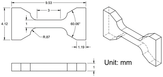
Figure 3.
Miniature tensile specimen part drawing [30].
It is worth noting that miniature specimens can impact the results as they tend to pick up on any inhomogeneities and anisotropies in the deposits. This is crucial for AM, especially as this allows for tensile specimens that are more sensitive to defects present, providing an in-depth understanding of AM critical flaws. Studies by Karnati et al. [31] and Michopoulos et al. [32] have explored the use of miniature tensile specimens with additive manufacturing. Karnati et al. [31] note that miniature tensile specimens display a wider spread in the data, but the overall strength values are comparable to ASTM tensile samples. The spread in the data is attributed to the greater sensitivity inherent in the sample design [31].
The data in this study utilized two significant figures in correlation with ASTM E29-22 Section 7.6 [33] for average and standard deviation values. Tensile strength is reported to the nearest 1 MPa in accordance with ASTM E8 Section 7.13.1 [34].
3. Results
3.1. Tensile Properties
The ultimate tensile strength (UTS) and elongation for each temperature at 2, 4, and 6 h are presented in Figure 4. A decreasing trend is noted for UTS across all times, but of note is that a minimal change is seen across different hold times for low temperatures. For example, at 300 °C, the median UTS values are 380, 371, and 384 MPa for 2, 4, and 6 h hold times, respectively. At 2 h, the elongation displays a parabolic trend, increasing until 350 °C, where the trend decreases with higher temperatures. This trend is not seen at 4 and 6 h. Instead, a slight decreasing trend is observed at 4 h, while no visible trend is observed at 6 h.
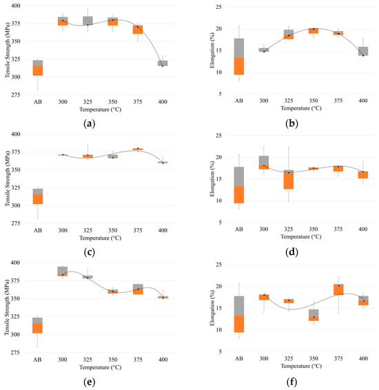
Figure 4.
UTS and elongation of Scalmalloy® treated at temperatures in the range of 300–400 °C at (a,b) 2 h, (c,d) 4 h, and (e,f) 6 h. Note: Orange block corresponds to the 25th percentile, the gray block the 75th percentile, and the interface between the orange and gray blocks is the median value. A trendline is plotted across the heat treatments to highlight the impact of changing temperature at constant time.
3.2. Microstructural Characterization
Five samples were selected for microstructural analysis based on the results presented in Section 3.1. Of these five samples, the as-built condition and 325 °C—4 h were chosen for analysis to act as standard cases. The as-built condition served as a basis for the comparison of all heat-treated cases to determine the success of the treatment, while the 325 °C—4 h case was selected as it is the manufacturer’s recommended treatment. The three remaining cases of the five chosen are 300 °C—2 h, 325 °C—2 h, and 350 °C—2 h. These three cases were selected for further analysis as the highest strengths were seen at 300 and 325 °C, with time playing a minimal role in the effect against tensile strength. From the data at 350 °C, time durations longer than 2 h were shown to affect the measured mechanical performance; so, the 350 °C—2 h case was selected as the pivotal point. Furthermore, for the cases at 300 °C and 350 °C, the chosen time duration was also 2 h to minimize the effects of time and allow for a clearer comparison and analysis of the temperature effects.
3.2.1. As-Built Microstructural Phenomenon of DED Scalmalloy®
Before the examination of the microstructures of interest in this study, it is important to briefly discuss the as-built condition and the impact that DED processing has on the Al3(Sc,Zr) phase during cooling. Figure 5 shows the microstructure of the as-built DED Scalmalloy®. Boillat-Newport et al. [28] examined the microstructure of DED Scalmalloy® and found that the as-built case had a very prevalent secondary phase, determined to be Al3(Sc,Zr). The Al3(Sc,Zr) phase formed during solidification rather than being induced by an age-hardening heat treatment [28]. This was also noted in other studies and linked to the cooling rates of DED, which are not fast enough to maintain the supersaturated solid solution, resulting in the precipitation of micron-sized Al3(Sc,Zr) [35]. Figure 5a highlights the presence of zones with larger and fewer precipitates in contrast to smaller and many precipitates found in other zones. This type of bimodal distribution is noted in SLM studies and is exaggerated, leading to the formation of coarse- and fine-grained regions. A higher magnification micrograph is presented in Figure 5b, which shows a representation of the morphology of the Al3(Sc,Zr) secondary phase that is heavily present in DED Scalmalloy®. The regions noted in Figure 5a are further detailed in the melt pool schematic in Figure 5c. This schematic highlights that these regions with many small particles of Al3(Sc,Zr) and a few large particles of Al3(Sc,Zr) are located primarily at the interface between the remelted and non-remelted sections of the deposits. The large particles were seen in the remelted regions as the result of growth during thermal cycling, while the small particles were located in the parts of the deposit that were not remelted.
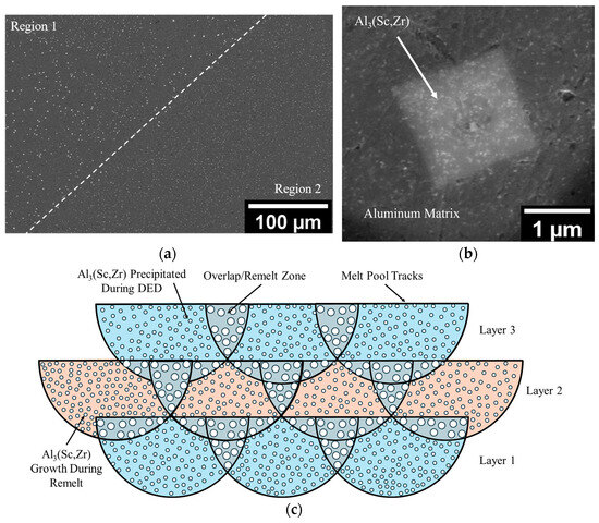
Figure 5.
As-built microstructure of DED Scalmalloy® showcasing the presence of an Al3(Sc,Zr) secondary phase: (a) micrograph showing two different regions with differing Al3(Sc,Zr) precipitates. Adapted with permission from Ref. [28], 2024, MDPI. (b) High magnification image of the Al3(Sc,Zr) precipitate. (c) Melt pool schematic showing the relationship between the regions shown in (a) and the melt track morphology, where the circles represent Al3(Sc,Zr) particles in two sizes, smaller in the non-remelted region and larger in the remelted. The dark line represents melt-pool boundaries across three layers.
From the analysis of the as-built condition for DED and the literature examination of the microstructure for as-built SLM, it is apparent that there are significant differences between the two processes. Baker et al. [36], in their study on AM titanium, noted that heat treatments for conventionally processed titanium may not provide optimal properties as expected with other manufacturing processes due to the variation in the microstructure of the starting material. Currently, the manufacturer recommends that Scalmalloy® be treated at 325 °C for 4 h to produce high tensile strengths above 500 MPa. However, as noted by Baker et al. [36], the likelihood of obtaining the same result through a single heat treatment of two differently fabricated samples is low. To date, SLM Scalmalloy® has been shown to produce the desired high strengths, while DED does not. Considering the differences between the processes and starting microstructure, it is clear that optimized properties cannot be achieved without process-specific treatments.
3.2.2. Al3(Sc,Zr) Phase Particles
Figure 6a provides a representational micrograph showing the presence of a secondary micron and sub-micron-sized phase. This phase has been noted in all heat-treated cases, as well as the as-built case, with the growth of the phase found with heat treatment due to coarsening. ImageJ v1.53k software was utilized in conjunction with SEM micrographs sourced from the TFS PRISMA to investigate the evolution of the phase particles from the as-built to heat-treated case (300 °C—2 h, 325 °C—2 h, 325 °C—4 h, and 350 °C—2 h). ImageJ was used to threshold the micrographs so that all unwanted features were eliminated and only the particles under investigation were visible. At least 1000 particles were analyzed for all cases, and the Feret diameter was determined.
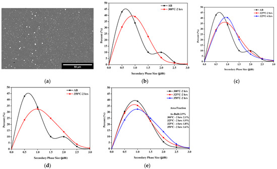
Figure 6.
Microstructural evolution of secondary phase particles: (a) representational micrograph at 300 °C—2 h depicting the micron- and sub-micron-sized particles; (b) AB vs. 300 °C; (c) AB vs. 325 °C; (d) AB vs. 350 °C; and (e) heat-treated case comparison.
Figure 6 also shows the size distribution for each case plotted against the as-built case. All heat-treated cases show an overall increase in the particle size compared to the as-built ones, as shown in Figure 6b–d. Figure 6e details the size evolution of each heat treatment relative to each other. The 300 °C—2 h case exhibited the narrowest distribution of the heat-treated cases. All other cases produced a broader distribution, with the 350 °C—2 h case exhibiting the widest distribution, highlighting the growth influenced by heat treatment. Figure 6e also shows the area fraction of the particles. Overall, it can be seen that, with the heat treatment, the particle size increased, while the number of particles decreased.
EDS analysis, shown in Figure 7, was utilized to identify the particle phase in Figure 6. The phase was primarily composed of aluminum, scandium, and zirconium. The standardized EDS composition of the phase is presented in Figure 7a. A small amount of magnesium is detected, but this is due to signals from the surrounding matrix material rather than the phase itself. Considering the EDS results and carefully examining the literature [37] leads to the conclusion that these particles are Al3(Sc,Zr). Al3(Sc,Zr) is a common phase in Scalmalloy® and provides a major strengthening mechanism that works by pinning grain boundaries. In addition to EDS, X-ray diffraction (XRD) was performed to further confirm the designation as Al3(Sc,Zr); however, due to the small content of the phase, it was not detected by XRD. This phenomenon has been noted by other researchers and is concluded to be related to the detection limit of the equipment utilized [28,38,39]. The EDS maps in Figure 7 show the elemental segregation of scandium and zirconium at the secondary Al3(Sc,Zr) phase. The matrix material around Al3(Sc,Zr) is primarily an aluminum solid solution, as noted by XRD.
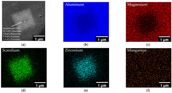
Figure 7.
Elemental EDS mapping of secondary phase particle in DED Scalmalloy®: (a) SEM image of secondary phase particle with quantitative EDS; (b) aluminum map; (c) magnesium map; (d) scandium map; (e) zirconium map; and (f) manganese map.
3.2.3. Al3(Sc,Zr) Nanoprecipitates
Figure 8a shows a representation of the nanoprecipitates analyzed using ImageJ to produce the size distributions presented in Figure 8b–e. When compared to the as-built condition, all heat treatments result in the growth of the nanoparticle phase. Furthermore, as noted at the micron scale, size evolves with the increase in the treatment temperature. Of note is that a difference can be seen between the distribution at 325 °C—2 h and 325 °C—4 h. This indicates that, while the effects of time at the lower temperatures are fairly negligible for tensile strength and micron-sized Al3(Sc,Zr), time considerably impacts the growth of the nano-sized precipitates.
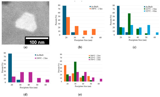
Figure 8.
Evolution of Al3(Sc,Zr) nanoprecipitates: (a) representational image of nanoprecipitates analyzed. Note: Micron-scale Al3(Sc,Zr) has a cut-off of 500 nm. Under 500 nm, it falls into the category of nanoprecipitates. (b) As-built vs. 300 °C; (c) as-built vs. 325 °C; (d) as-built vs. 350 °C; and (e) 2 h heat-treated case comparison.
3.2.4. Grain Evolution
Figure 9 shows representative images of EBSD grain maps for the as-built, 300 °C—2 h, and 350 °C—2 h cases. Compared to the as-built case, all heat-treated cases show an increased grain size with a greater coarsening exhibited by increased temperatures. Table 2 details the average and maximum grain size for each case, indicating that, as the temperature increased, the grain size also increased. A similar trend was noted with the size evolution of the secondary Al3(Sc,Zr) micron phase. Cases that exhibited an increase in Al3(Sc,Zr) size also exhibited a greater grain growth, indicating that, as the strengthening phase grew, it was not able to pin the grain boundaries effectively.
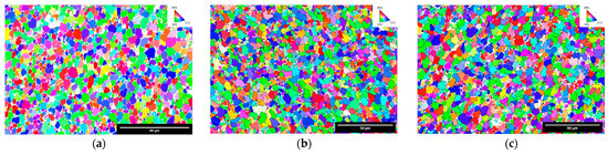
Figure 9.
EBSD maps depicting the grain size evolution and texture orientation: (a) as-built. Reprinted with permission from Ref. [28], MDPI, 2024; (b) 300 °C—2 h; and (c) 350 °C—2 h showing an increase in the grain size with higher aging temperatures.
Table 2.
Equivalent circle diameter grain size determined through EBSD analysis.
4. Discussion
4.1. Impact of Heat Treatment on Tensile Behavior
Several studies have noted the peak aging condition for Scalmalloy® fabricated via SLM to be around 325–350 °C, and treatment at higher temperatures deteriorated the properties [8,40]. Spierings et al. noted that aging at high temperatures and long hold times can result in overaging and a lower mechanical strength [8]. The use of excessive heat treatment temperatures negatively impacts the strengthening of the alloy, which can be linked to a diminished tensile strength [8,40]. Ma et al. found that increased temperatures increase the precipitation and coarsening rate for secondary Al3(Sc,Zr) particles [40]. Furthermore, when aging is performed at high temperatures (above 350 °C) and for long times, the alloy strength starts to decrease due to the coarsening of precipitated Al3(Sc,Zr) particles and loss of coherency between the particles and the matrix [40]. This weakens the strengthening mechanism, as dislocation motion and grain growth cannot be effectively hindered [40]. The trends noted in the literature correlate with the trends shown here and are best seen with the 2 h treatment condition shown in Figure 4a, where treatment at 375 °C and 400 °C results in property deterioration compared to that at lower temperatures at 2 h. This trend is still present at 4 and 6 h, but the temperature at which the properties begin to deteriorate is lower due to the addition of the time factor at longer aging hold times.
While similar trends are shown in this study and the literature regarding diminished strength when aged above the peak aging temperatures, the strength values of SLM Scalmalloy® are distinctly higher than those of DED Scalmalloy®. It is worth noting that there is a distinct lack of data on heat-treated DED Scalmalloy® as most studies only present the as-built case. This is in sharp contrast to SLM Scalmalloy® studies, in which extensive analyses of heat treatments have been conducted. Table 3 details the average tensile properties from the literature studies that fabricated Scalmalloy® and similar Al-Mg-Sc-Zr-based alloys via AM processing.
Table 3.
Tensile properties of AM-fabricated Scalmalloy® and similar Al-Mg-Sc-Zr-based compositions.
As is clear from examining the table, the values of DED-fabricated Scalmalloy® across the board, this study included, are surpassed by the properties made possible with SLM fabrication. As discussed above, SLM and DED are two different processes with considerable differences that can cause property value differences. SLM has a considerably faster cooling rate that can more effectively form the supersaturated solid solution upon solidification, which is the precursor to precipitation during aging. DED, being a slower cooling process, cannot maintain the supersaturated solid solution, and an Al3(Sc,Zr) phase can form before precipitation during aging [35,38]; refer to Figure 5. This limits the potential for nanoprecipitates, which provide much of the strengthening for Scalmalloy® and pin the grain boundaries to promote Hall–Petch strengthening [35]. This is detailed further in the next section. The tensile properties in this study are on the higher end of the properties reported for DED-fabricated Scalmalloy®. The research by Awd et al. explored both the SLM and DED fabrication of Scalmalloy® [16]. The tensile properties reported by Awd et al. highlight the detrimental effect of defects on mechanical behavior. Compared to this study, the tensile behavior seen by Awd et al. is surpassed due to the minimization of defects and application of post-processing heat treatment, demonstrating the potential for the DED processing of Scalmalloy®. Furthermore, DED researchers, understanding the potential of compositions with scandium and zirconium, have explored other Al-Mg-Sc-Zr alloys, as seen in Table 3. Of note is that some studies show similar results to those presented in this investigation. Thus, this study can act as the first step toward optimizing the heat treatment for each unique alloy.
4.2. Heat-Treated Microstructural Evolution
Figure 6 and Figure 9 show that heat treatment plays a crucial role in the microstructural evolution of a Scalmalloy® deposit. The micron- and sub-micron-sized Al3(Sc,Zr) phase noted in Figure 6 showed an increase in size and decrease in number with heat treatment. In general, higher temperatures and longer times result in larger Al3(Sc,Zr) phase particles, with fewer of them being present. This indicates that the application of either higher temperatures or longer times than needed to facilitate the nanoprecipitation of Al3(Sc,Zr) from solid solution impacts coarsening and promotes the growth of large particles at the expense of smaller ones. Similarly, the nanoprecipitates, seen in Figure 8, show a strong temperature dependence, with the nanoprecipitate size increasing as the heat treatment temperature increases. Furthermore, unlike the micron-sized Al3(Sc,Zr), time impacts the nano-scale precipitates’ size evolution. This is seen well when considering the nanoprecipitate evolution at 325 °C—2 h and 325 °C—4 h. After 4 h at 325 °C, the nanoprecipitates showed larger sizes and a wider size distribution than found at 2 h, indicating that small time differences play an effect. However, this effect is not significant enough to be shown on a larger scale. It is theorized that this would be much more drastic and found in both the micron-scale Al3(Sc,Zr) and tensile behaviors at considerably longer times.
The grain size of the heat-treated cases, as seen in Figure 9 and Table 2, surpasses the grain size of the as-built condition, indicative of coarsening occurring with the application of heat during the artificial aging treatment to promote nanoprecipitation. The grain size is strongly tied to the Al3(Sc,Zr) phase particles (micron and sub-micron) and nanoprecipitates. Al3(Sc,Zr) has been found in many studies to be a very effective strengthening mechanism, stabilizing the microstructure by pinning grain boundaries and promoting strengthening via the Hall–Petch effect. As Al3(Sc,Zr) evolves with the application of heat treatments, the effectiveness of grain boundary pinning and strengthening is impacted. Cases with high temperatures and/or long processing times provide coarsening during and after precipitation, leading to larger sizes for Al3(Sc,Zr), as seen in Figure 6, while lower temperatures and shorter times lead to less coarsening.
4.3. Microstructure and Tensile Behavior
This study highlights that the largest grain size, nanoprecipitates, and micron/sub-micron Al3(Sc,Zr) phase occurs at higher temperatures, as seen at 350 °C, relative to lower temperatures. Furthermore, as the temperature increases, the tensile strength decreases. This can be linked to microstructural evolution and the weakening of the strengthening potential. Much of Scalmalloy®’s strength stems from the ability of the nanoprecipitates to pin the grain boundaries, preventing dislocation motion. As the size of the precipitates increases, the number of them decreases, and the ability to hinder dislocation motion becomes stunted.
From this study, the data indicate that there is a threshold where treatment yields an overaged condition and provides properties below the peak aged properties possible. This occurs at temperatures above 350 °C for shorter treatment times (such as 2 h) or at 350 °C for longer times. Heat treatment promotes the growth of nanoprecipitates from the supersaturated solid solution and provides a coarsening effect that grows the precipitates and, subsequently, the grains. This study shows that the tensile strength is maximized at 300 °C and 325 °C; however, the growth of the grains and Al3(Sc,Zr) is greater at 325 °C.
Marquis and Seidman explored the impact of the temperature on the coarsening rate of an Al-0.3 wt%Sc alloy and determined that the coarsening rate increases dramatically with the temperature [45]. The coarsening rate dependence on the temperature from Marquis and Seidman shows that the coarsening rate relative to the temperature is not linear [45]. Each temperature increase, even 50 °C, produces a substantial increase in coarsening [45]. Thus, it is desired to utilize a treatment temperature that can still produce the nanoprecipitates that provide strengthening while minimizing the coarsening rate. From this study, it is recommended for DED Scalmalloy® that heat treatment be performed at 300 °C to allow for nanoprecipitation to occur, providing strengthening and improving tensile behavior, while minimizing the coarsening rate. This recommendation for the treatment at 300 °C differs from the manufacturer’s 325 °C at 4 h. It is theorized that the need for lower temperatures is not just linked to the minimization of coarsening but also influenced by the fact that the cooling rates for DED are slower than with SLM, resulting in Al3(Sc,Zr) falling out of solution and forming before artificial aging. Thus, the amount of solute available for the precipitation of nanoparticles is lowered and could be a strong driving force for the application of a lower temperature treatment to promote precipitation and control coarsening. This highlights the distinct differences between DED and SLM and the need for process-specific treatments.
5. Conclusions
This study investigated the application of post-processing heat treatments to improve the tensile strength of DED-processed Scalmalloy®. The examination of the results of this study allows the following conclusions to be drawn:
- The post-processing heat treatment of DED Scalmalloy® components improved UTS relative to the as-built case. After treatment at 300 °C, the UTS improved by 20.4%.
- Tensile strength decreased with the increase in the treatment temperatures, with the effect being significantly noticed at temperatures above 325 °C. At 300 and 325 °C, the time was noted not to impact tensile behavior significantly; however, at temperatures of 350 °C and above, time becomes more important and influences behavior.
- Micron-sized and nano-sized Al3(Sc,Zr) exhibited a strong temperature dependence, with the size increasing as the treatment temperature increased. The examination of the micron-sized phase at 325 °C—2 h and 325 °C—4 h shows minimal time dependence at low temperatures and shorter periods. However, this was not the case when examining the nanoprecipitates treated at 325 °C over 2 and 4 h. The nanoprecipitate distribution at 2 h relative to the 4 h case was narrower. The 4 h case exhibited a wider distribution and larger sizes, indicating that, while no impact is seen for low temperatures and short hold times on the micron scale, there is, in fact, an effect that is visible at the nano-scale.
- The examination of the microstructure indicates that the grain size increases with higher treatment temperatures. Compared to the as-built case, the treatments at 300 °C—2 h, 325 °C—4 h, and 350 °C—2 h yielded 19.1, 26.2, and 35.7% increases, respectively. The grain size evolution correlates with the increase in micron- and nano-sized Al3(Sc,Zr), exhibiting the weakening ability for grain pinning and the subsequent diminishment of the Hall–Petch strengthening made possible by smaller grains. This can be linked to the decreasing trend noted for the tensile strength.
From the results found in this study, it is recommended that the heat treatment for DED Scalmalloy® occur at short times and as low temperatures as possible. It was shown that the tensile strength when treated at 300° was on par with the treatment at 325 °C. The examination of the microstructure shows the growth of Al3(Sc,Zr) and the grains with a small increase in the temperature from 300 to 325 °C. It is suggested that the treatment be performed at 300 °C rather than 325 °C to minimize coarsening. While this study did not yield the same high properties noted with SLM, this is the beginning step towards the optimization of the DED process to improve the resulting process. Furthermore, this study specifically targeted Scalmalloy®; however, the results shown in this paper can act as a guideline and promote the optimization of similar Al-Mg-Sc-Zr-based compositions.
Author Contributions
Conceptualization, R.B.-N. and S.P.I.; methodology, R.B.-N. and S.P.I.; formal analysis, R.B.-N.; writing—original draft preparation, R.B.-N.; writing—review and editing, R.B.-N. and S.P.I.; supervision, F.L.; project administration, F.L.; funding acquisition, S.P.I. and F.L. All authors have read and agreed to the published version of the manuscript.
Funding
This study was supported by DoEdu GAANN Grant # P200A210100, NSF Grants CMMI 1625736, and NSF EEC 1937128, Navair Contract # N6833520C0029 by way of Product Innovation and Engineering, LLC., the Intelligent Systems Center (ISC), and Material Research Center (MRC) at Missouri S&T. Their financial support is greatly appreciated.
Data Availability Statement
Data are contained within the article.
Acknowledgments
The authors would like to acknowledge the support from Nam Pham, project manager for Navair Contract # N6833520C0029. Additional thanks to the Intelligent Systems Center (ISC) and Materials Research Center (MRC) for their help in sample preparation and testing. Lastly, the authors also want to acknowledge the contributions of Ranjit Joy and Braden Mclain for their assistance in sample fabrication and tensile testing, Clarissa Wisner from the Advanced Materials Characterization Lab (AMCL) at Missouri S&T for her assistance with SEM analysis, and JH Technologies for EBSD microscopy.
Conflicts of Interest
The authors declare no conflicts of interest.
References
- Altıparmak, S.C.; Yardley, V.A.; Shi, Z.; Lin, J. Challenges in additive manufacturing of high-strength aluminium alloys and current developments in hybrid additive manufacturing. Int. J. Light. Mater. Manuf. 2021, 4, 246–261. [Google Scholar] [CrossRef]
- Yang, H.; Sha, J.; Zhao, D.; He, F.; Ma, Z.; He, C.; Shi, C.; Zhao, N. Defects control of aluminum alloys and their composites fabricated via laser powder bed fusion: A review. J. Mater. Process. Technol. 2023, 319, 118064. [Google Scholar] [CrossRef]
- Dixit, S.; Liu, S. Laser Additive Manufacturing of High-Strength Aluminum Alloys: Challenges and Strategies. J. Manuf. Mater. Process. 2022, 6, 156. [Google Scholar] [CrossRef]
- Zafar, F.; Reis, A.; Vieira, M.; Emadinia, O. Additively Manufactured High-Strength Aluminum Alloys: A Review. In Recent Advancements in Aluminum Alloys; Rajendrachari, D.S., Ed.; IntechOpen: Rijeka, Yugoslavia, 2023; ISBN 978-1-83768-510-3. [Google Scholar]
- Martin, J.H.; Yahata, B.D.; Hundley, J.M.; Mayer, J.A.; Schaedler, T.A.; Pollock, T.M. 3D printing of high-strength aluminium alloys. Nature 2017, 549, 365. [Google Scholar] [CrossRef] [PubMed]
- Ekubaru, Y.; Gokcekaya, O.; Ishimoto, T.; Sato, K.; Manabe, K.; Wang, P.; Nakano, T. Excellent strength–ductility balance of Sc-Zr-modified Al–Mg alloy by tuning bimodal microstructure via hatch spacing in laser powder bed fusion. Mater. Des. 2022, 221, 110976. [Google Scholar] [CrossRef]
- Spierings, A.B.; Dawson, K.; Heeling, T.; Uggowitzer, P.J.; Schäublin, R.; Palm, F.; Wegener, K. Microstructural features of Sc- and Zr-modified Al-Mg alloys processed by selective laser melting. Mater. Des. 2017, 115, 52–63. [Google Scholar] [CrossRef]
- Spierings, A.B.; Dawson, K.; Kern, K.; Palm, F.; Wegener, K. SLM-processed Sc- and Zr-modified Al-Mg alloy: Mechanical properties and microstructural effects of heat treatment. Mater. Sci. Eng. A 2017, 701, 264–273. [Google Scholar] [CrossRef]
- Cabrera-Correa, L.; González-Rovira, L.; de Dios López-Castro, J.; Castillo-Rodríguez, M.; Botana, F.J. Effect of the heat treatment on the mechanical properties and microstructure of Scalmalloy® manufactured by Selective Laser Melting (SLM) under certified conditions. Mater. Charact. 2023, 196, 112549. [Google Scholar] [CrossRef]
- Schimbäck, D.; Kaserer, L.; Mair, P.; Palm, F.; Leichtfried, G.; Pogatscher, S.; Hohenwarter, A. Deformation and fatigue behaviour of additively manufactured Scalmalloy® with bimodal microstructure. Int. J. Fatigue 2023, 172, 107592. [Google Scholar] [CrossRef]
- Kuo, C.N.; Peng, P.C.; Liu, D.H.; Chao, C.Y. Microstructure evolution and mechanical property response of 3d-printed scalmalloy with different heat-treatment times at 325 °C. Metals 2021, 11, 555. [Google Scholar] [CrossRef]
- Carpenter Additive Scalmalloy Datasheet. Available online: https://www.carpenteradditive.com/hubfs/Resources/Data%20Sheets/Scalmalloy_Datasheet.pdf (accessed on 18 June 2024).
- Baig, S.; Ghiaasiaan, S.R.; Shamsaei, N. Effect of Heat Treatment on the Microstructure and Mechanical Properties of LB-PBF AlSi10Mg and Scalmalloy. In Proceedings of the Light Metals 2021; Perander, L., Ed.; Springer International Publishing: Cham, Switzerland, 2021; pp. 119–125. [Google Scholar]
- Li, R.; Chen, H.; Zhu, H.; Wang, M.; Chen, C.; Yuan, T. Effect of aging treatment on the microstructure and mechanical properties of Al-3.02Mg-0.2Sc-0.1Zr alloy printed by selective laser melting. Mater. Des. 2019, 168, 107668. [Google Scholar] [CrossRef]
- Deng, C.; Li, R.; Yuan, T.; Niu, P.; Wang, Y. Microstructure and Mechanical Properties of a Combination Interface between Direct Energy Deposition and Selective Laser Melted Al-Mg-Sc-Zr Alloy. Metals 2021, 11, 801. [Google Scholar] [CrossRef]
- Awd, M.; Tenkamp, J.; Hirtler, M.; Siddique, S.; Bambach, M.; Walther, F. Comparison of Microstructure and Mechanical Properties of Scalmalloy® Produced by Selective Laser Melting and Laser Metal Deposition. Mater 2017, 11, 17. [Google Scholar] [CrossRef] [PubMed]
- Gao, B.; Zhao, H.; Peng, L.; Sun, Z. A Review of Research Progress in Selective Laser Melting (SLM). Micromachines 2022, 14, 57. [Google Scholar] [CrossRef] [PubMed]
- Gokuldoss, P.K.; Kolla, S.; Eckert, J. Additive Manufacturing Processes: Selective Laser Melting, Electron Beam Melting and Binder Jetting-Selection Guidelines. Materials 2017, 10, 672. [Google Scholar] [CrossRef] [PubMed]
- Kim, J.; Wakai, A.; Moridi, A. Materials and manufacturing renaissance: Additive manufacturing of high-entropy alloys. J. Mater. Res. 2020, 35, 1963–1983. [Google Scholar] [CrossRef]
- Gibson, B.T.; Mhatre, P.; Borish, M.C.; Atkins, C.E.; Potter, J.T.; Vaughan, J.E.; Love, L.J. Controls and process planning strategies for 5-axis laser directed energy deposition of Ti-6Al-4V using an 8-axis industrial robot and rotary motion. Addit. Manuf. 2022, 58, 103048. [Google Scholar] [CrossRef]
- Gouveia, J.R.; Pinto, S.M.; Campos, S.; Matos, J.R.; Sobral, J.; Esteves, S.; Oliveira, L. Life Cycle Assessment and Cost Analysis of Additive Manufacturing Repair Processes in the Mold Industry. Sustainability 2022, 14, 2105. [Google Scholar] [CrossRef]
- Svetlizky, D.; Das, M.; Zheng, B.; Vyatskikh, A.L.; Bose, S.; Bandyopadhyay, A.; Schoenung, J.M.; Lavernia, E.J.; Eliaz, N. Directed energy deposition (DED) additive manufacturing: Physical characteristics, defects, challenges and applications. Mater. Today 2021, 49, 271–295. [Google Scholar] [CrossRef]
- Dass, A.; Moridi, A. State of the Art in Directed Energy Deposition: From Additive Manufacturing to Materials Design. Coatings 2019, 9, 418. [Google Scholar] [CrossRef]
- Yap, C.Y.; Chua, K.; Dong, Z.; Liu, Z.; Zhang, D.; Loh, L.E.; Sing, S.L. Review of selective laser melting: Materials and applications. Appl. Phys. Rev. 2015, 2, 41101. [Google Scholar] [CrossRef]
- Ahn, D.-G. Directed Energy Deposition (DED) Process: State of the Art. Int. J. Precis. Eng. Manuf. Technol. 2021, 8, 703–742. [Google Scholar] [CrossRef]
- Herzog, D.; Seyda, V.; Wycisk, E.; Emmelmann, C. Additive manufacturing of metals. Acta Mater. 2016, 117, 371–392. [Google Scholar] [CrossRef]
- Najmon, J.C.; Raeisi, S.; Tovar, A. Review of Additive Manufacturing Technologies and Applications in the Aerospace Industry. In Additive Manufacturing for the Aerospace Industry; Froes, F., Boyer, R., Eds.; Elsevier: Amsterdam, The Netherlands, 2019; ISBN 978-0-1281-4062-8. [Google Scholar]
- Boillat-Newport, R.; Isanaka, S.P.; Kelley, J.; Liou, F. Heat Treatments for Minimization of Residual Stresses and Maximization of Tensile Strengths of Scalmalloy® Processed via Directed Energy Deposition. Materials 2024, 17, 1333. [Google Scholar] [CrossRef] [PubMed]
- Boillat, R.; Isanaka, S.P.; Liou, F. The Effect of Nanostructures in Aluminum Alloys Processed Using Additive Manufacturing on Microstructural Evolution and Mechanical Performance Behavior. Crystals 2021, 11, 524. [Google Scholar] [CrossRef]
- Kelley, J. Influence of Alloy Composition on the Process Robustness of Steels Consolidated via Laser-Directed Energy Deposition, Missouri University of Science and Technology. 2023. Available online: https://repositories.lib.utexas.edu/items/63015677-378b-4f1e-adbf-76d56a5ab816 (accessed on 18 June 2024).
- Karnati, S.; Isanaka, S.P.; Zhang, Y.; Liou, F.F.; Schulthess, J.L. A Comparative Study on Representativeness and Stochastic Efficacy of Miniature Tensile Specimen Testing. Mater. Perform. Charact. 2022, 11, 424–439. [Google Scholar] [CrossRef]
- Michopoulos, J.G.; Iliopoulos, A.P.; Steuben, J.C.; Kittur, M.; Phan, N.; A Salem, A.; Satko, D.P.; Karnati, S.; Isanaka, S.P.; Liou, F. Multiscale Data Driven Methodology for Accelerating Qualification and Certification of Additively Manufactured Parts. In Encyclopedia of Materials: Metals and Alloys Volume 3; Caballero, F.G., Ed.; Elsevier: Oxford, UK, 2022; pp. 223–244. ISBN 978-0-12-819733-2. [Google Scholar]
- ASTM E29-22 Standard; Practice for Using Significant Digits in Test Data to Determine Conformance with Specifications. ASTM International: West Conshohocken, PA, USA, 2022.
- ASTM E8-24 Standard; Test Methods for Tension Testing of Metallic Materials. ASTM International: West Conshohocken, PA, USA, 2024.
- Michi, R.A.; Plotkowski, A.; Shyam, A.; Dehoff, R.R.; Babu, S.S. Towards high-temperature applications of aluminium alloys enabled by additive manufacturing. Int. Mater. Rev. 2022, 67, 298–345. [Google Scholar] [CrossRef]
- Baker, A.H.; Collins, P.C.; Williams, J.C. New Nomenclatures for Heat Treatments of Additively Manufactured Titanium Alloys. JOM 2017, 69, 1221–1227. [Google Scholar] [CrossRef]
- Pan, D.; Zhou, S.; Zhang, Z.; Li, M.; Wu, Y. Effects of Sc(Zr) on the microstructure and mechanical properties of as-cast Al–Mg alloys. Mater. Sci. Technol. 2017, 33, 751–757. [Google Scholar] [CrossRef]
- Martucci, A.; Aversa, A.; Manfredi, D.; Bondioli, F.; Biamino, S.; Ugues, D.; Lombardi, M.; Fino, P. Low-Power Laser Powder Bed Fusion Processing of Scalmalloy®. Materials 2022, 15, 3123. [Google Scholar] [CrossRef] [PubMed]
- Jeyaprakash, N.; Yang, C.-H.; Kumar, M.S. Influence of coherent intermetallic nano-precipitates on the nano-level mechanical and tribological properties of the Laser-Powder bed fused Scalmalloy. Mater. Charact. 2022, 193, 112269. [Google Scholar] [CrossRef]
- Ma, R.; Peng, C.; Cai, Z.; Wang, R.; Zhou, Z.; Li, X.; Cao, X. Manipulating the microstructure and tensile properties of selective laser melted Al–Mg-Sc-Zr alloy through heat treatment. J. Alloys Compd. 2020, 831, 154773. [Google Scholar] [CrossRef]
- Schimbäck, D.; Mair, P.; Kaserer, L.; Perfler, L.; Palm, F.; Leichtfried, G.; Pogatscher, S. An improved process scan strategy to obtain high-performance fatigue properties for Scalmalloy®. Mater. Des. 2022, 224, 111410. [Google Scholar] [CrossRef]
- Shakil, S.I.; González-Rovira, L.; Cabrera-Correa, L.; de Dios López-Castro, J.; Castillo-Rodríguez, M.; Botana, F.J.; Haghshenas, M. Insights into laser powder bed fused Scalmalloy®: Investigating the correlation between micromechanical and macroscale properties. J. Mater. Res. Technol. 2023, 25, 4409–4424. [Google Scholar] [CrossRef]
- Wang, Z.; Lin, X.; Kang, N.; Hu, Y.; Chen, J.; Huang, W. Strength-ductility synergy of selective laser melted Al-Mg-Sc-Zr alloy with a heterogeneous grain structure. Addit. Manuf. 2020, 34, 101260. [Google Scholar] [CrossRef]
- Wang, Z.; Zeng, L.; Lin, X.; Wang, J.; Feng, Z.; Dang, C.; Li, H.; Wang, Y.; Huang, W. Microstructural evolution and strengthening mechanisms of additively-manufactured Al-Mg-Sc-Zr alloys: Laser directed energy deposition versus laser powder bed fusion. J. Alloys Compd. 2024, 985, 173946. [Google Scholar] [CrossRef]
- Marquis, E.A.; Seidman, D.N. Nanoscale structural evolution of Al3Sc precipitates in Al(Sc) alloys. Acta Mater. 2001, 49, 1909–1919. [Google Scholar]
Disclaimer/Publisher’s Note: The statements, opinions and data contained in all publications are solely those of the individual author(s) and contributor(s) and not of MDPI and/or the editor(s). MDPI and/or the editor(s) disclaim responsibility for any injury to people or property resulting from any ideas, methods, instructions or products referred to in the content. |
© 2024 by the authors. Licensee MDPI, Basel, Switzerland. This article is an open access article distributed under the terms and conditions of the Creative Commons Attribution (CC BY) license (https://creativecommons.org/licenses/by/4.0/).