Article

Ferroelectric and Structural Properties of Cobalt-Doped Lead Ferrite Thin Films Formed by Reactive Magnetron Sputtering

by
Benas Beklešovas
,
Vytautas Stankus
,
Aleksandras Iljinas
and
Liutauras Marcinauskas
*
Department of Physics, Kaunas University of Technology, Studentų Str. 50, LT-51368 Kaunas, Lithuania
*
Author to whom correspondence should be addressed.
Crystals 2024, 14(8), 721; https://doi.org/10.3390/cryst14080721 (registering DOI)
Submission received: 25 June 2024 / Revised: 6 August 2024 / Accepted: 7 August 2024 / Published: 12 August 2024
(This article belongs to the Special Issue Magnetoelectric Materials and Their Application)

Abstract

:
Cobalt-doped lead ferrite (Pb2Fe2O5) thin films were deposited by reactive magnetron sputtering. The influence of the cobalt concentration and synthesis temperature on the structure, phase composition and ferroelectric properties of Pb2Fe2O5 thin films was investigated. It was determined that the increase in deposition temperature increased the grain size and density of the Co-doped PFO thin films. The XRD data demonstrated that the Co-doped Pb2Fe2O5 thin films consisted of Pb2Fe2O5 and PbO phases with a low amount of CoO and Co3O4 phases. The increase in the cobalt concentration in the Pb2Fe2O5 films slightly enhanced the cobalt oxide phase content. Polarization dependence on electric field measurement demonstrated that the highest ferroelectric properties of the Co-doped Pb2Fe2O5 films were obtained when the synthesis was performed at 550 °C temperatures. The increase in the cobalt concentration in the films enhanced the remnant polarization and coercive field values. It was found that the Co-doped Pb2Fe2O5 film deposited at 550 °C temperature and containing 10% cobalt had the highest remnant polarization (72 µC/cm2) and coercive electric field (105 kV/cm).

1. Introduction

Multiferroic materials are multifunctional materials that demonstrate the interaction of different primary ferroic properties such as ferroelectricity, ferromagnetism, and ferroelasticity [1,2,3,4]. Among the diverse interactions of ferroic properties, significant attention has been given to the relationship between ferroelectric and magnetic characteristics. [5]. The possibility to control the ferroelectric and magnetic properties in the same phase provides the ability to develop a wide range of applications on non-volatile memory devices, transducers, magnetic field sensors, etc. [6,7,8,9,10,11]. Special attention is paid to the solid-state memories where multiferroics enable the possibility to write data electrically and read magnetically and this results in high storage density and low-power consumptions. Two simultaneous mechanisms occur: ferroelectricity arises from transition ions possessing empty d orbitals, while magnetism necessitates transition metal ions with partially filled d orbitals. Consequently, these two ordered states mutually exclude each other. Most multiferroic materials suffer some shortcomings such as low Neel temperature, which narrows the group of materials that can be integrated into applications used at room temperature; therefore, the need to search for new multiferroics or improve those already discovered remains [12,13]. In the past 15 years, great progress towards discovering and developing multiferroics has been made. Lead ferrite Pb2Fe2O5 (PFO) is recognized as a promising multiferroic material known for exhibiting concurrent ferroelectric and magnetic properties under ambient conditions [14,15,16]. Even though the current–voltage loops and measurements with voltage pulses [17,18] are not reported in the literature, the entire body of work performed on this material strongly supports ferroelectricity with the remnant polarization estimated to be Pr ~ 0.22 μC/cm2 at room temperature [15]. The non-centrosymmetric structures, influenced by the presence of 6s2 lone pairs and covalent Pb-O bonds, contribute to ferroelectricity, whereas magnetism arises from the B site (Fe3+) [15].
Although the results are promising, there is always room for improvement. There are some key problems such as high leakage current and lower magnetoelectric coupling coefficients that need to be overcome. In order to solve this problem, the doping with additional metal may be used. Altering the core properties of multiferroics is acknowledged as an effective approach. PFO properties could be modified by substitution of Pb2+ (A-site) and Fe3+ (B-site) ions. Fe3+ (0.64 Å) ion has a similar radius as Cr3+ (0.76 Å), Ti4+ (0.68 Å), and Mn3+ (0.72 Å) ions, which could substitute the Fe3+ ion at B-site [19,20,21]. However, using aliovalent as dopants, a charge compensation with respect to changing the cation valance should be considered. Therefore, the charge neutrality would be maintained and possibly the oxygen vacancies would be avoided using isovalent ion such as Cr3+, Ni2+, Co2+, or Nb5+ [20,22,23,24]. Here, both Fe3+ and dopant ions occupy the B-site randomly, potentially leading to distortions in the cation–oxygen octahedral arrangement. This structure leads to varied superexchange interactions among the Fe-O polyhedra at the corners and neighboring units along the shared edges of the Fe–O5 tetrahedral pyramids.
The aim of this work was to synthesize the cobalt-doped lead ferrite thin films and to investigate the influence of the cobalt concentration and synthesis temperature on the surface morphology, phase structure and ferroelectric properties of the lead ferrite thin films. This study introduces cobalt-doped lead ferrite (Pb2Fe2O5) thin films, a novel approach to enhance the ferroelectric properties of multiferroics at ambient conditions. By varying the cobalt concentration and synthesis temperature, we systematically investigate their effects on the surface morphology, phase structure, and ferroelectric properties. This work addresses key challenges such as high leakage current, aiming to optimize PFO’s performance for functional materials applications. The findings provide new insights into doping strategies to significantly improve the ferroelectric properties, which is crucial for practical applications.

2. Materials and Methods

Cobalt-doped lead ferrite Pb2Fe2O5 was deposited using the reactive magnetron sputtering technique [25,26]. Platinized silicon Pt/Ti/SiO2/Si multilayer system with layers thickness of 200 nm, 20 nm, 1 µm and 380 µm, respectively, was used as the substrate for thin film synthesis. Each element (Pb, Fe and Co) had a separate high-purity target (99.99%). The distance between the target and substrate was maintained at 60 mm. A crucial component in achieving high-quality films is the seeding layer, for which titanium was chosen. The titanium seeding layer was produced using reactive magnetron sputtering in a pure argon gas atmosphere at an operating pressure of 1.3 Pa. To achieve a layer thickness of 5 nm, the synthesis temperature was maintained at 750 °C, with the duration carefully adjusted. After depositing the seeding layer, the substrate temperature was reduced to 500 °C, and the gas environment was switched to O2, with a constant working pressure of 1.3 Pa. [27]. Three magnetrons were utilized for each element to form the lead ferrite thin films in situ over a period of 1 h. The dopant content was regulated by using slits of different widths over the dopant magnetron. For measuring the material properties, the capacitor was constructed with an aluminum top electrode. These electrodes were deposited using thermal evaporation. The films of PFO with cobalt concentrations of 3%, 5%, and 10% (by %wt), denoted as PFOCo3, PFOCo5, and PFOCo10, respectively, have been prepared.
X-ray diffraction patterns of the PFO films were registered with a Bruker D8 series diffractometer using monochromatic CuKα radiation with Bragg–Brentano geometry. The ferroelectric hysteresis loop measurements of films were examined using Sawyer and Tower method (resistance of 1 kΩ and reference capacitor of 150 nF was used in the circuit at 50 Hz frequency and 25 °C) [26,28]. Scanning electron microscopy (SEM) imaging was performed by the S-3400N measurement system using a 10 kV operating voltage. The EDS measurements of Co distribution were performed by Bruker Quad 5040 spectrometer (AXS Microanalysis GmbH, Hamburg, Germany).

3. Results

The Co-doped PFO thin films were deposited on the heated substrates at 550 °C temperature. The X-ray diffraction patterns of the formed undoped and cobalt-doped lead ferrite thin films are given in Figure 1. It was obtained that the peaks obtained at 32°, 38.2°, 46°and 56° 2θ angles are attributed to Pb2Fe2O5 phase in the undoped PFO film [14,16]. The diffraction peaks at 32°, 38.2°, 46°and 56° are attributed to (220), (312), (400) and (424) crystallographic planes, respectively [16]. Meanwhile, only the (312) and (424) planes of the Pb2Fe2O5 phase were obtained in the Co-doped PFO thin films (Figure 1). The decrease in the main peak of Pb₂Fe₂O₅ (PFO) in X-ray diffraction (XRD) measurements with the addition of Co dopant can be attributed to several interrelated factors. When the cobalt ions are introduced into the PFO lattice, they replace iron ions due to their similar but not identical ionic radii. This substitution creates lattice distortions because Co2⁺ ions are slightly larger than Fe³⁺ ions, disrupting the regular crystal structure. These distortions lead to a decrease in the crystallinity, causing the change in the diffraction peaks. Changes in the preferred orientation of the crystals could also contribute to the peak reduction. Doping with Co might alter the way the crystals grow and orient themselves, resulting in a redistribution of peak intensities where some peaks become less pronounced or nearly disappear, while others might become more noticeable (Figure 1).
The XRD data indicated that the intensity of the PFO diffraction peaks remained unchanged with the increase in the cobalt concentration. Additionally, the cobalt oxide phases were obtained in the Co-doped PFO films. The peaks observed at 32.5° and 35° correspond to the Co3O4 and CoO phases, respectively. The intensity of the CoO peak does not change with the increase in the cobalt concentration from 3% to 5% [29]. Meanwhile, the CoO peak intensity was reduced when the highest concentration of cobalt was used (Figure 1). The EDS measurements indicated that the concentration of the cobalt was ~3.5 wt.% and ~10.3 wt.% for the PFOCo3 and PFOCo10 films, respectively. The peaks at 30.5°, 34°, 36°, 37° and 54° 2θ angles are due to the formation of the PbO phase [30]. The intensity of the PbO phase peaks throughout all Co-doped PFO films was very similar. The phase distribution within the PFOCo3 film was evaluated using XRD peak area integration, focusing on the PbO, Co3O4, CoO, and PFO phases. The Pt phase, being the substrate material, was excluded from the analysis. It was found that PbO peaks collectively contributed to 43.1% of the integrated area, the Co3O4 peak contributed only to 0.9% of the integrated area, and the CoO phase peak was dominant and resulted in 51.5%. The peaks attributed to the PFO phase contributed to 4.5% of the integrated area. These results indicate a significant presence of cobalt and lead oxides in the Co-doped PFO films.
The PFO phase peaks exhibit a slight shift to higher 2θ angles, as indicated by the dashed line in the inset of Figure 1. This minor shift can be attributed to the ionic radius of Co2⁺ (0.61 Å) being similar to that of Fe³⁺ (0.64 Å). This similarity in ionic radii permits the substitution of Co2⁺ for Fe³⁺ without inducing significant lattice distortion. Consequently, the minimal lattice strain results in largely unaffected peak positions. Both undoped and doped PFO lattices exist in the structures, resulting in a corresponding variation. Another very important aspect is related to an iron ion of different valence (Fe3+ and Fe2+). Such conversion of Fe leads to the appearance of oxygen vacancies in the coatings. When the films are doped with cobalt, the charge compensation occurs as Fe3+ ions are replaced by Co2+ ions [31,32,33,34].
To investigate the influence of synthesis temperature, the PFOCo10 thin film, which has the highest cobalt content, was selected. The films were deposited at 500 °C, 550 °C and 600 °C temperatures. A comparison of the XRD spectra of PFOCo10 coatings within the temperature range of 500–600 °C is presented in Figure 2. The peaks attributed to the PFO phases (220), (312), (440) and (424) are detected at 2θ angles of 32°, 38°, 46° and 56°, respectively [14,16]. At a synthesis temperature of 500 °C, the most intense peak is related to (220) PFO phase and the intensity of this peak decreases with increasing the deposition temperature (Figure 2). The intensity of the (312) peak increased, and peak became broader with the increase in the deposition temperature. Such a change in the peak intensities may be due to the process of lead backscattering (due to desorption and evaporation), when the stoichiometry is violated. A Co3O4 phase at 32.5° is also presented in XRD pattern, in addition to the CoO peak (35°) detected in the previous Co-doped PFO films. As the synthesis temperature was enhanced to 550 °C, a low-intensity peak at 58° was formed and is attributed to the Co3O4 phase. As the synthesis temperature was increased, the peak intensity of the Co3O4 phase at 32.5° was drastically reduced [29]. It indicated that the possibility of the substitution of Fe3+ ions with Co2+ ions takes place more efficiently at lower deposition temperatures [31,34,35]. The peaks of PbO phases are detected at 2θ angles of 30°, 34°, 36°, 37° and 54°, with an additional peak at 53° observed exclusively in the film synthesized at 500 °C [30]. As the temperature increased, their intensities slightly varied, but the peak positions remained unchanged. This variation in peak intensity of the PbO phase can be attributed to changes in the stoichiometry of the film resulting from different synthesis temperatures, due to a higher lead desorption and evaporation at higher temperatures. It should be noted that the PFO phase remained unchanged with the increase in the synthesis temperature from 550 °C to 600 °C.
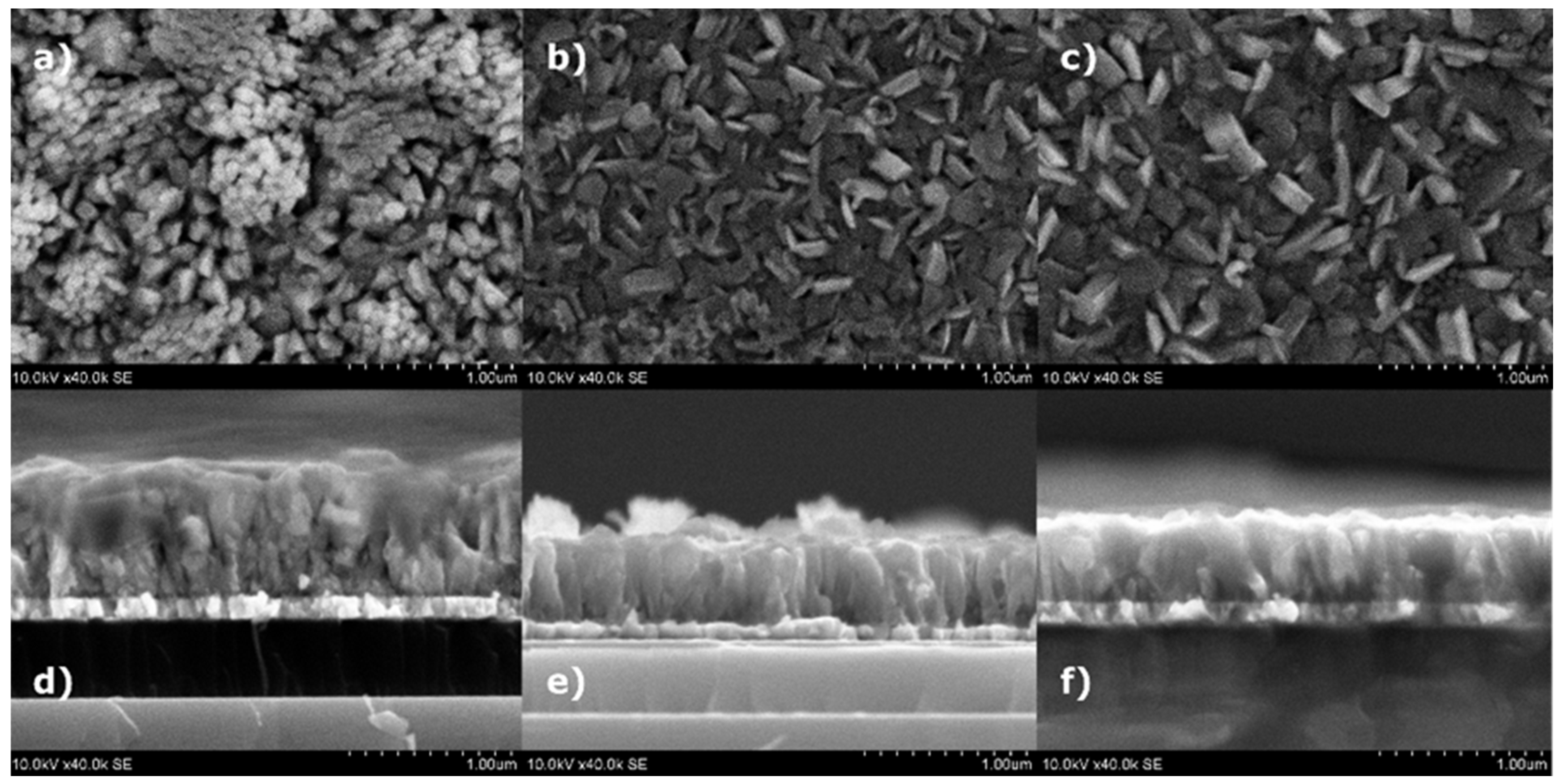
SEM surface and cross-section views of PFOCo10 films deposited in the temperature range of 500–600 °C are given in Figure 3. Grain structures and their boundaries are clearly visible in all as-deposited thin films (Figure 3a–c). In the film deposited at 500 °C, agglomerates of smaller structures have formed, resulting in larger size grains. The gaps and voids are visible on the surface between the grains, which indicates the low density of the film. The shape of the grains is influenced by the direction of ion flow during the magnetron sputtering [36]. The sample holder on which the coatings are formed moves in a semicircular trajectory over the cathodes of the magnetron, so the direction of the ion flow is varied. For this reason, the formation of structures of various shapes occurs, which is also analyzed in the study of Bairagi et al. [37]. As the synthesis temperature was enhanced to 550 °C (Figure 3b), the formation into clusters disappeared, and the grains became denser with noticeable sparsely spaced spaces between them. As the temperature of film synthesis was enhanced, the dimensions of the grains also increased, which filled the previous gaps and formed a dense structure. The average dimensions of the grains at the synthesis temperatures of 500 °C, 550 °C and 600 °C were 105 nm, 290 nm and 340 nm, respectively. The larger grain dimensions in the films at higher synthesis temperatures are determined by higher adatom energy; thus, the atoms will diffuse larger distances to the growth centers and will lead to the growth of more dense structures [38,39,40].
In the films deposited at 500 °C (Figure 3d), the cross-sectional view shows a cone-shaped columnar growth. The column has the same diameter for half of its height, but as it continues to grow, its diameter begins to widen, forming a cone-like structure. Such structure formation can be caused by a lower temperature, as a result of which the atoms do not diffuse and immediately localize when they reach the film. After reaching these structures, the following atoms also immediately form bonds and do not diffuse, so some atoms can be localized on the sides of the column as if they were hanging. As the synthesis temperature increases to 550 °C (Figure 3e), a dense arrangement of columns is observed, and cone-shaped structures are no longer observed. As the temperature further increases to 600 °C (Figure 3f), even denser and larger columns are formed. Columns are well blended with each other; in some places, it is difficult to see the grain boundaries. The formation of structures at temperatures of 550 °C and 600 °C can be determined by the higher energy of the atoms. Atoms that reach the substrate can diffuse, thus forming denser structures [31,38,39,40]. It should be noted that the lead has a relatively low melting temperature (~327 °C). At higher temperatures, such as 600 °C, lead atoms will gain more kinetic energy, which increases their tendency to evaporate, desorb, or sublimate from the film’s surface. The lead, iron, or cobalt atoms on the surface will gain more kinetic energy at higher temperatures. It will enhance the surface diffusion and mobility of atoms on the substrate and result in the formation of more dense but lower-thickness films. The average thickness of the films decreased with the increase in the synthesis temperature due to the formation of denser structures. It was determined that the thickness of the Co-doped PFO films were 770 nm, 510 nm and 460 nm when the synthesis temperatures were 500 °C, 550 °C and 600 °C, respectively.
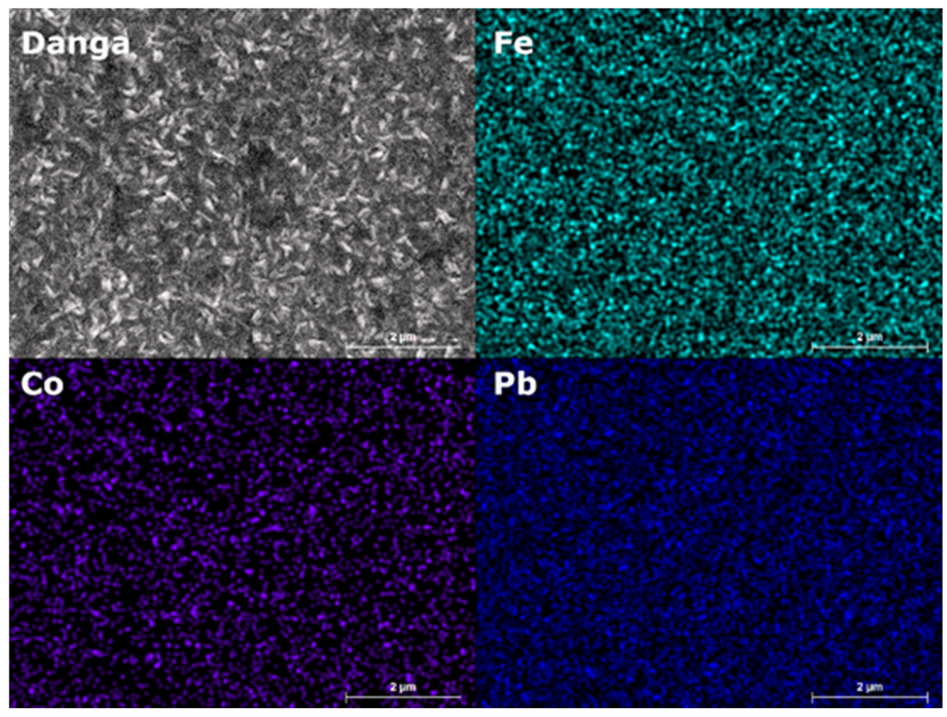
The distribution of major elements in a PFOCo10 film deposited at 550 °C is given in Figure 4. As can be seen, Fe and Pb metals are densely and evenly distributed over the entire surface of the film, with no additional artifacts observed. Cobalt is also evenly distributed but appears less frequently compared to iron and lead due to its lower concentration. The uniform distribution of elements observed in the EDS mapping indicates that elements such as Pb, Co, and O are evenly dispersed throughout the film. It was found that the cobalt concentration was 10.3 ± 0.5 wt.%. The amount of oxygen was 17.9 ± 0.9 wt.%. Meanwhile, the iron and lead concentrations were 43.9 ± 1.5 wt.% and 27.8 ± 1.3 wt. %, respectively. The phases detected by XRD, such as CoO, PbO, and Co₃O₄, are likely present in a finely dispersed or nanocrystalline form, which aligns with the uniform appearance in EDS mapping images.
The authors aimed to obtain a pure PFO phase, but so far, using the existing parameters (substrate temperature and Co dopants concentration), the pure PFO phases were not formed. The purpose of the research was to show the peculiarities of the formation of PFO phases, which showed that it is not possible to avoid the formation of the residual phases so far. It may be necessary to change or introduce other process parameters, such as reducing the deposition rate, using a bias voltage, using the HIPIMS method, using a mixture of argon and oxygen instead of pure oxygen, etc. On the other hand, Abakumov et al. [41] and Wang et al. [16] observed that the chemical formula of lead ferrite is defined as PbFeO2,5−xPbO (where x = 0.0625, 0.1 and 0.125) due to the formation of crystallographic shear planes and the appearance of defects during synthesis. As can be seen from the general formula, it is difficult to avoid the formation of a secondary lead oxide phase and to determine whether the PbO are individual crystallites or a component of the shear planes.
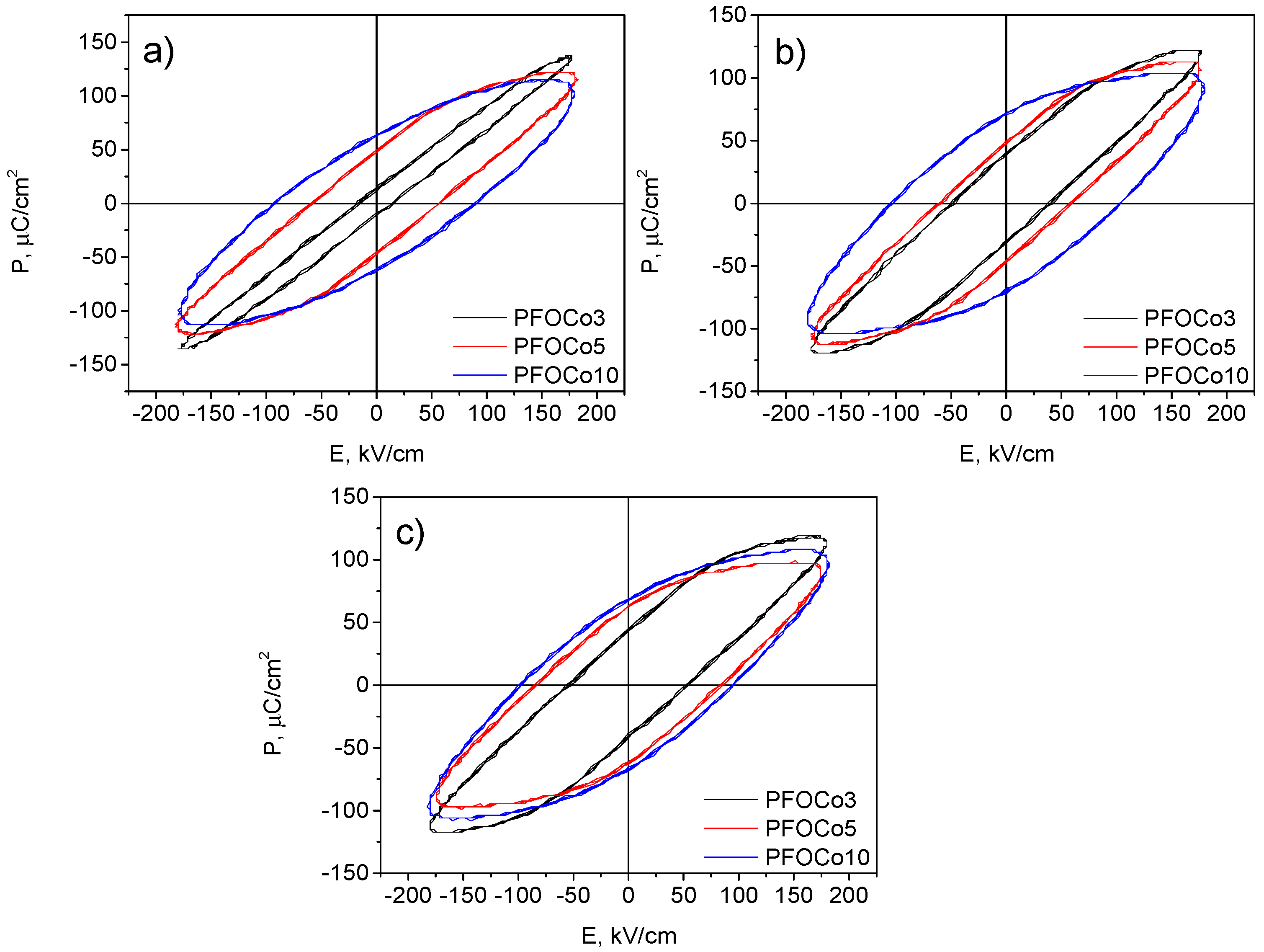
P-E hysteresis loop dependence on the applied electrical field of cobalt-doped PFO films was measured by using a Sawyer and Tower circuit at room temperature. The P-E hysteresis loop of Co-doped PFO thin films deposited with the various cobalt concentrations and synthesis temperatures are presented in Figure 5. It should be noted that all deposited films demonstrated the oval forms of hysteresis loops. It indicates that the full saturation was not reached due to too relatively high leakage currents (Figure 5). The complete polarization saturation was not achieved for the Co-doped PFO films deposited at 500 °C. The saturation of polarization decreased from 129 µC/cm2 to 115 µC/cm2 with the increase in cobalt concentration from 3 to 10% (Figure 5a). By increasing the concentration of cobalt, a significant increase in the remnant polarization and the coercive field values was observed. This increase in the remnant polarization and coercive field is likely related to both structural deformations in the Co-doped PFO lattice and possible variations in phase compositions. While structural deformations due to cobalt incorporation can contribute to the changes in ferroelectric properties, the presence of different phases, as detected in XRD analysis, may also play a significant role. A similar trend in ferroelectric properties occurs in the films formed at 550 °C temperatures. The highest polarization value of 121 µC/cm2 was obtained for the PFO film with the lowest concentration of the cobalt. A slight reduction in the polarization down to 103 µC/cm2 was observed when the highest amount of cobalt was used (Figure 5b). However, the remnant polarization and the coercive field values were enhanced with the increase in Co concentration in the PFO films. As the deposition temperature was increased to 600 °C, the saturation level of the P-E hysteresis loops of Co-doped PFO thin films was slightly reduced (Figure 5c). It should be noted that the increase in deposition temperatures leads to a slight transformation of the P-E hysteresis loops from an oval shape into a more rectangular shape. The leakage currents in all thin films possibly occurred due to the existing defects in the Co-doped PFO films and the substitution of the valence of the Fe3+ ion for the Fe2+ ion, which determined the generation of oxygen vacancies in the crystal lattice [19,42].
The comparison of the remnant polarization and coercive electric field values of the Co-doped PFO films depending on the cobalt concentration at various synthesis temperatures is given in Figure 6. Our previous investigations [14,28] demonstrated that with an increase in synthesis temperature, the ferroelectric properties of Pb2Fe2O5 gradually deteriorate. The remnant polarization was reduced from 54 μC/cm2 to ~38 μC/cm2 and the coercive field from ~69 kV/cm to ~23 kV/cm. Meanwhile, the doping of PFO films with cobalt leads to an improvement in the ferroelectric properties. The remnant polarization was enhanced from 9 µC/cm2 to 63 µC/cm2, and the coercive field from 15 kV/cm to 90 kV/cm, when the Co concentration was increased from 3% to 10%, for the films deposited at 500 °C (Figure 6a). The ferroelectric properties were enhanced as the synthesis temperature of Co-doped PFO films was enhanced to 550 °C. The remnant polarization and coercive field were increased from 29 µC/cm2 to 72 µC/cm2 and from 39 kV/cm to 105 kV/cm, respectively. The increase in the synthesis temperature up to 600 °C indicates that the ferroelectric properties of the Co-doped PFO films were slightly enhanced when the cobalt concentrations were 3% and 5% (Figure 6c). However, the remnant polarization and coercive field values of the PFO film with 10% cobalt were 67 µC/cm2 and 94 kV/cm, respectively, which is slightly lower compared to the Co-doped PFO film deposited at 550 °C temperature. The increase in spontaneous polarization in all films with the enhancement of the cobalt content can be related to the difference in sizes of transition metal ions: RFe3+ = 0.645 Å and RCo2+ = 0.65 Å, which leads to the lattice distortions [42,43].
The summary of the main results presented in Figure 6 showed that the deposition temperature as well as the cobalt concentration have a huge effect on the ferroelectric properties of the films. It was observed that the highest values of the remnant polarization (72 µC/cm2) and coercive field (105 kV/cm) were when the synthesis temperature was 550 °C. Such a non-linear variation in the ferroelectric properties of the films could be due to the ineffective exchange of Fe3+ ions with Co2+ in the lattice. Those results were confirmed by the XRD data analysis of the films (Figure 1 and Figure 2). The formation of a low amount of cobalt oxide phases at a temperature of 500 °C. As the temperature increased, the content of the CoO phase was reduced, and the ferroelectric properties were enhanced. However, the evaporation of the lead was enhanced with the increase in the deposition temperature up to 600 °C [14]. When lead deficiency appeared, additional defects were formed together with oxygen vacancies, which probably led to slightly higher leakage currents and a reduction in remnant polarization values for the Co-doped PFO film with 10% of cobalt. It should be highlighted that the final ferroelectric properties of the Co-doped PFO films could be controlled by the cobalt concentration and the synthesis temperature [19].

4. Conclusions

Cobalt-doped lead ferrite thin films were deposited at various temperatures using layer-by-layer reactive magnetron sputtering. The Co-doped PFO thin films consisted of the Pb2Fe2O5 and PbO phases; additionally, a small amount of CoO and Co3O4 phases were observed. The increase in the synthesis temperature from 500 °C to 600 °C resulted in the reduction in the Co3O4 phase in the films. The increase in the synthesis temperature led to the formation of the larger size grains and thinner Co-doped PFO thin films. It was observed that the density, crystallite sizes, and electrical properties of Co-doped PFO films strongly depended on the synthesis temperature and cobalt concentration. The remnant polarization and coercive field of the PFOCo3 films increased from 9 µC/cm2 to 38 µC/cm2 and from 15 kV/cm to 54 kV/cm, respectively, with the increase in the synthesis temperature. The increase in the cobalt content in the PFO films enhanced the electrical properties of the films. It was observed that the PFO film with 10% cobalt deposited at 550 °C temperature demonstrated the highest values of remnant polarization (72 µC/cm2) and coercive field (105 kV/cm). The performed study showed that the electrical properties of the co-doped PFO films could be controlled by changing the dopant concentration and synthesis temperature.

Author Contributions

Conceptualization, V.S. and B.B.; methodology, V.S. and A.I.; formal analysis, B.B., V.S., A.I. and L.M.; investigation, B.B. and V.S.; data curation, B.B. writing—original draft preparation, B.B., A.I., L.M. and V.S.; writing—review and editing, B.B., V.S., A.I. and L.M.; visualization, B.B.; supervision, B.B. and V.S. All authors have read and agreed to the published version of the manuscript.

Funding

This research received no external funding.

Data Availability Statement

The original contributions presented in the study are included in the article, further inquiries can be directed to the corresponding author.

Conflicts of Interest

The authors declare no conflicts of interest.

References

  1. Huang, W.; Yang, S.; Li, X. Multiferroic heterostructures and tunneling junctions. J. Mater. 2015, 1, 263–284. [Google Scholar] [CrossRef]
  2. Khomskii, D.I. Multiferroics: Different ways to combine magnetism and ferroelectricity. J. Magn. Magn. Mater. 2006, 306, 1–8. [Google Scholar] [CrossRef]
  3. Roy, S.; Majumder, S.B. Recent advances in multiferroic thin films and composites. J. Alloys Compd. 2012, 538, 153–159. [Google Scholar] [CrossRef]
  4. Sekine, Y.; Akiyoshi, R.; Hayami, S. Recent advances in ferroelectric metal complexes. Coord. Chem. Rev. 2022, 469, 214663. [Google Scholar] [CrossRef]
  5. Kadomtseva, A.M.; Popov, Y.F.; Pyatakov, A.P.; Vorob’ev, G.P.; Zvezdin, A.K.; Viehland, D. Phase transitions in multiferroic BiFeO3 crystals, thin-layers, and ceramics: Enduring potential for a single phase, room-temperature magnetoelectric ‘holy grail’. Phase Transit. 2006, 79, 1019–1042. [Google Scholar] [CrossRef]
  6. Amirov, A. Chapter 15—Multiferroic, magnetic, and magnetoelectric nanomaterials for medical applications. In Magnetic Materials and Technologies for Medical Applications; Tishin, A.M., Ed.; Woodhead Publishing: Sawston, UK, 2022; pp. 469–484. [Google Scholar] [CrossRef]
  7. Pati, D.K.; Das, P.R.; Parida, B.N.; Padhee, R. Multifunctional characterization of multiferroic [Pb(Fe0.5Nb0.5)O3]0.5–[(Ca0.2Sr0.8)TiO3]0.5 for storage and photocatalytic applications. Ceram. Int. 2022, 48, 19344–19357. [Google Scholar] [CrossRef]
  8. Rahul, M.T.; Chacko, S.K.; Vinodan, K.; Raneesh, B.; Philip, K.A.; Bhadrapriya, B.C.; Bose, B.A.; Kalarikkal, N.; Rouxel, D.; Viswanathan, P.; et al. Multiferroic and energy harvesting characteristics of P(VDF-TrFE)-CuFe2O4 flexible films. Polymer 2022, 252, 124910. [Google Scholar] [CrossRef]
  9. Shah, J.; Verma, K.C.; Agarwal, A.; Kotnala, R.K. Novel application of multiferroic compound for green electricity generation fabricated as hydroelectric cell. Mater. Chem. Phys. 2020, 239, 122068. [Google Scholar] [CrossRef]
  10. Singh Pawar, M.; Raj, A.; Kumar Singh, A.; Tuli, V.; Anshul, A.; Kumar, M. Lead-free ‘Ca’ doped Bi0.80La0.20FeO3 multiferroic material for solar cell applications. Mater. Today Proc. 2022, 67, 713–718. [Google Scholar] [CrossRef]
  11. Vopson, M.M. Fundamentals of Multiferroic Materials and Their Possible Applications. Crit. Rev. Solid State Mater. Sci. 2015, 40, 223–250. [Google Scholar] [CrossRef]
  12. Alkathy, M.S.; Rahman, A.; Zabotto, F.L.; Milton, F.P.; Raju, K.C.J.; Eiras, J.A. Room-temperature multiferroic behaviour in Co/Fe co-substituted layer-structured Aurivillius phase ceramics. Ceram. Int. 2022, 48, 30041–30051. [Google Scholar] [CrossRef]
  13. Ren, X.; Han, Y.; Chen, X.; Fu, Y.; Wang, F.; Hu, K.; Sun, Z.; Zhang, K. Room-temperature multiferroicity and magnetoelectric couplings in (Co0.75Al0.25)2(Fe0.75Mg0.25)O4 spinel films. J. Alloys Compd. 2022, 920, 165918. [Google Scholar] [CrossRef]
  14. Beklešovas, B.; Stankus, V.; Link, J.; Stern, R. Structural, ferroelectric and magnetic properties of lead ferrite (Pb2Fe2O5) thin films synthesized by reactive magnetron deposition. Thin Solid Film. 2020, 708, 138124. [Google Scholar] [CrossRef]
  15. Hadermann, J.; Abakumov, A.M.; Nikolaev, I.V.; Antipov, E.V.; Van Tendeloo, G. Local structure of perovskite-based “Pb2Fe2O5”. Solid State Sci. 2008, 10, 382–389. [Google Scholar] [CrossRef]
  16. Wang, M.; Tan, G. Multiferroic properties of Pb2Fe2O5 ceramics. Mater. Res. Bull. 2011, 46, 438–441. [Google Scholar] [CrossRef]
  17. Dawber, M.; Rabe, K.; Scott, J. Physics of thin-film ferroelectric oxides. Rev. Mod. Phys. 2005, 77, 1083–1130. [Google Scholar] [CrossRef]
  18. Rabe, K.M.; Dawber, M.; Lichtensteiger, C.; Ahn, C.H.; Triscone, J.-M. Modern Physics of Ferroelectrics: Essential Background; Springer: Berlin/Heidelberg, Germany, 2007. [Google Scholar]
  19. Chauhan, S.; Kumar, M.; Yousuf, A.; Rathi, P.; Sahni, M.; Singh, S. Effect of Na/Co co-substituted on structural, magnetic, optical and photocatalytic properties of BiFeO3 nanoparticles. Mater. Chem. Phys. 2021, 263, 124402. [Google Scholar] [CrossRef]
  20. Makhdoom, A.R.; Akhtar, M.J.; Rafiq, M.A.; Siddique, M.; Iqbal, M.; Hasan, M.M. Enhancement in the multiferroic properties of BiFeO3 by charge compensated aliovalent substitution of Ba and Nb. AIP Adv. 2014, 4, 037113. [Google Scholar] [CrossRef]
  21. Sinha, A.K.; Bhushan, B.; Jagannath; Sharma, R.K.; Sen, S.; Mandal, B.P.; Meena, S.S.; Bhatt, P.; Prajapat, C.L.; Priyam, A.; et al. Enhanced dielectric, magnetic and optical properties of Cr-doped BiFeO3 multiferroic nanoparticles synthesized by sol-gel route. Results Phys. 2019, 13, 102299. [Google Scholar] [CrossRef]
  22. Hoque, M.M.; Islam, M.T.; Islam, M.R.; Zubair, M.A. Effective bandgap tuning with non-trivial modulation in room temperature magnetic and electrical responses of low level Ba–Cr co-substituted BiFeO3 nanoparticles. Ceram. Int. 2022, 48, 19583–19596. [Google Scholar] [CrossRef]
  23. Khan, U.; Nairan, A.; Irfan, M.; Naz, S.; Wu, D.; Gao, J. Magnetic properties of Ni/BiFeO3 hybrid nanostructures. J. Alloys Compd. 2022, 912, 165133. [Google Scholar] [CrossRef]
  24. Tefera Kebede, M.; Devi, S.; Dillu, V.; Chauhan, S. Effects of Sm and Cr co-doping on structural, magnetic, optical and photocatalytic properties of BiFeO3 nanoparticles. Mater. Sci. Eng. B 2022, 283, 115859. [Google Scholar] [CrossRef]
  25. Beklešovas, B.; Iljinas, A.; Stankus, V.; Čyvienė, J.; Andrulevičius, M.; Ivanov, M.; Banys, J. Structural, Morphologic, and Ferroelectric Properties of PZT Films Deposited through Layer-by-Layer Reactive DC Magnetron Sputtering. Coatings 2022, 12, 717. [Google Scholar] [CrossRef]
  26. Iljinas, A.; Stankus, V. Structural and ferroelectric properties of bismuth ferrite thin films deposited by direct current reactive magnetron sputtering. Thin Solid Film. 2016, 601, 106–110. [Google Scholar] [CrossRef]
  27. Iljinas, A.; Stankus, V.; Čyvienė, J.; Abakevičienė, B. Formation of PbTiO3 thin films on seed layers using DC magnetron layer-by-layer deposition. Vacuum 2015, 122, 310–313. [Google Scholar] [CrossRef]
  28. Beklešovas, B.; Stankus, V.; Abakevičienė, B.; Link, J.; Stern, R.; Plyushch, A.; Banys, J.; Čyvienė, J.; Girčys, R.; Bašinskas, M.; et al. Synthesis and Characterization of Cr-Doped Pb2Fe2O5 Thin Films by Reactive Magnetron Sputtering. ECS J. Solid State Sci. Technol. 2023, 12, 103014. [Google Scholar] [CrossRef]
  29. Wang, X.; Ge, H.; Ye, Q.; Si, P.; Chen, H. Weak Ferromagnetism and Exchange Bias in Antiferromagnetic Cobalt Oxide Nanoparticles. J. Magn. 2018, 23, 487–490. [Google Scholar] [CrossRef]
  30. Gil, D.M.; Nieva, G.; Franco, D.G.; Gómez, M.I.; Carbonio, R.E. Lead nitroprusside: A new precursor for the synthesis of the multiferroic Pb2Fe2O5, an anion-deficient perovskite. Mater. Chem. Phys. 2013, 141, 355–361. [Google Scholar] [CrossRef]
  31. Bai, L.; Sun, M.; Ma, W.; Yang, J.; Zhang, J.; Liu, Y. Enhanced magnetic properties of co-doped BiFeO3 thin films via structural progression. Nanomaterials 2020, 10, 1798. [Google Scholar] [CrossRef]
  32. Sinha, A.; Bhushan, B.; Gupta, N.; Sen, S.; Prajapat, C.; Nuwad, J.; Bhatt, P.; Mishra, S.; Meena, S.; Priyam, A. Effect of cobalt-doping on dielectric, magnetic and optical properties of BiFeO3 nanocrystals synthesized by sol–gel technique. Solid State Sci. 2020, 102, 106168. [Google Scholar] [CrossRef]
  33. You, S.; Zhang, B. Enhanced magnetic properties of cobalt-doped bismuth ferrite nanofibers. Mater. Res. Express 2020, 7, 046102. [Google Scholar] [CrossRef]
  34. Zhang, M.; Yang, H.-J.; Li, Y.; Cao, W.-Q.; Fang, X.-Y.; Yuan, J.; Cao, M.-S. Cobalt doping of bismuth ferrite for matched dielectric and magnetic loss. Appl. Phys. Lett. 2019, 115, 212902. [Google Scholar] [CrossRef]
  35. Sales, J.N.B.d.; da Silva, R.; Lara, L.R.S.; Ramos, S.L.; Soares, J.d.S.; Soares, T.A.S.; Machado, G.; Manhabosco, S.M.; de Oliveira, A.; de Carvalho, H. Structural, optical, and magnetic evaluation of Co-, Ni-, and Mn-modified multiferroic BiFeO3 ceramics. Ceram. Int. 2021, 47, 24564–24573. [Google Scholar] [CrossRef]
  36. Barranco, A.; Borras, A.; Gonzalez-Elipe, A.R.; Palmero, A. Perspectives on oblique angle deposition of thin films: From fundamentals to devices. Prog. Mater. Sci. 2016, 76, 59–153. [Google Scholar] [CrossRef]
  37. Bairagi, S.; Järrendahl, K.; Eriksson, F.; Hultman, L.; Birch, J.; Hsiao, C.-L. Glancing angle deposition and growth mechanism of inclined AlN nanostructures using reactive magnetron sputtering. Coatings 2020, 10, 768. [Google Scholar] [CrossRef]
  38. Cartwright, J.H.; Escribano, B.; Piro, O.; Sainz-Diaz, C.I.; Sánchez, P.A.; Sintes, T. Ice Film Morphologies and the Structure Zone Model. In Proceedings of the AIP Conference Proceedings; American Institute of Physics: College Park, ML, USA, 2008; pp. 696–701. [Google Scholar]
  39. Kaiser, N. Review of the fundamentals of thin-film growth. Appl. Opt. 2002, 41, 3053–3060. [Google Scholar] [CrossRef]
  40. Chinchay-Espino, H.A.; Montes-Albino, G.M.; Morales-Cruz, C.M.; Dobbertin-Sanchez, S.E.; Rojas-Flores, S. Effect of Cobalt Substitution on the Structural and Magnetic Properties of Bismuth Ferrite Powders. Crystals 2022, 12, 1058. [Google Scholar] [CrossRef]
  41. Abakumov, A.M.; Hadermann, J.; Bals, S.; Nikolaev, I.V.; Antipov, E.V.; Van Tendeloo, G. Crystallographic Shear Structures as a Route to Anion-Deficient Perovskites. Angew. Chem. Int. Ed. 2006, 45, 6697–6700. [Google Scholar] [CrossRef] [PubMed]
  42. Khan, U.; Adeela, N.; Javed, K.; Riaz, S.; Ali, H.; Iqbal, M.; Han, X.; Naseem, S. Influence of cobalt doping on structural and magnetic properties of BiFeO3 nanoparticles. J. Nanoparticle Res. 2015, 17, 1–9. [Google Scholar] [CrossRef]
  43. Coondoo, I.; Panwar, N.; Tomar, A.; Bdikin, I.; Kholkin, A.; Puli, V.S.; Katiyar, R.S. Improved magnetic and piezoresponse behavior of cobalt substituted BiFeO3 thin film. Thin Solid Film. 2012, 520, 6493–6498. [Google Scholar] [CrossRef]
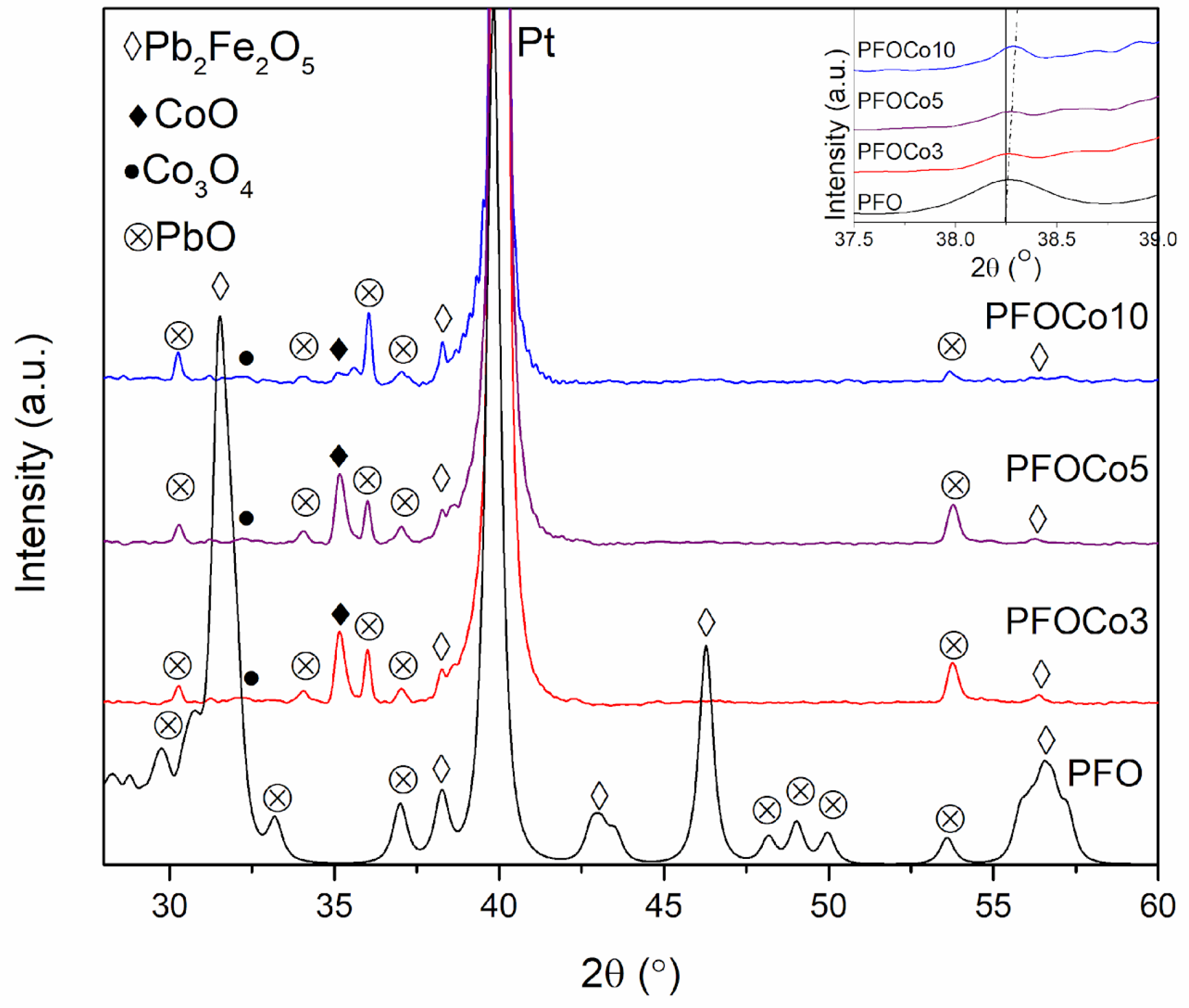
Figure 1. The XRD pattern of the Co-doped PFO thin films synthesized at 550 °C.
Crystals 14 00721 g001
Figure 2. XRD spectra of PFOCo10 films deposited at different temperatures.
Crystals 14 00721 g002
Figure 3. SEM images and cross-section views of PFOCo10 films deposited at (a,d) 500 °C, (b,e) 550 °C and (c,f) 600 °C.
Crystals 14 00721 g003
Figure 4. EDX mapping images of the PFOCo10 film deposited at 550 °C temperature.
Crystals 14 00721 g004
Figure 5. Comparison of the influence of cobalt content on the PFO P-E curves at different synthesis temperatures: (a) 500 °C; (b) 550 °C; (c) 600 °C.
Crystals 14 00721 g005
Figure 6. Effect of cobalt concentration on ferroelectric properties of PFO films deposited at (a) 500 °C; (b) 550 °C and (c) 600 °C temperatures.
Crystals 14 00721 g006
Disclaimer/Publisher’s Note: The statements, opinions and data contained in all publications are solely those of the individual author(s) and contributor(s) and not of MDPI and/or the editor(s). MDPI and/or the editor(s) disclaim responsibility for any injury to people or property resulting from any ideas, methods, instructions or products referred to in the content.