Article

Surface Modification of Chromium–Nickel Steel by Electrolytic Plasma Nitriding Method

1
“PlasmaScience” LLP, Ust-Kamenogorsk 070000, Kazakhstan
2
Research Center “Surface Engineering and Tribology”, S. Amanzholov East Kazakhstan University, Ust-Kamenogorsk 070000, Kazakhstan
*
Author to whom correspondence should be addressed.
Crystals 2024, 14(9), 759; https://doi.org/10.3390/cryst14090759
Submission received: 29 July 2024 / Revised: 16 August 2024 / Accepted: 18 August 2024 / Published: 26 August 2024

Abstract

:
Electrolytic plasma nitriding is an attractive chemical heat treatment used to improve the surface properties of steel by implementing nitrogen saturation. This method is widely applied to steel and iron-based alloys operating under various operating conditions. In this work, using liquid-phase plasma nitriding technology, a nitrided layer was obtained on the surface of 40CrNi steel in electrolytes of different concentrations. The microstructure and phase composition of the nitrided layer were investigated and analyzed using scanning electron microscopy (SEM) and X-ray diffraction (XRD), and we performed Vickers hardness and wear resistance tests using the ball-on-disc method. The microhardness and wear resistance of nitrided 40CrNi steel were significantly improved due to the lubricating properties of the ε-Fe2N phase formed on its surface.

1. Introduction

Nowadays, alloyed and special steels are chosen for manufacturing machine parts operating under conditions of high mechanical and thermal effects accompanied by impact loads [1]. However, surface layers often need additional hardening. Currently, there is already an array of scientific research on various technological methods of surface hardening of metal alloys to improve the functional properties of surface layers, such as heat treatment [2], including the use of concentrated energy flows of different nature [3], and chemical–thermal treatment [4]. However, the potential of their efficiency has been exhausted. Therefore, recently, numerous studies have been conducted to develop duplex technologies combining known processes [4,5]. But the empirical approach and the associated costs of numerous experiments to establish regularities between technological parameters and the resulting structure and properties do not allow to control structure formation and make them uncompetitive for production.
Also, in mechanical engineering technology, when modifying the surface layers of steels and alloys, multicomponent chemical heat treatment (CHT) can be effectively used, which consists of simultaneous or sequential diffusion saturation of the surface with several chemical elements [6]. Complex methods of chemical heat treatment such as nitriding and carbonitriding can significantly increase the resistance to wear, as well as increasing the corrosion resistance and a number of other properties of the surface layers of machine parts [7]. Nevertheless, the problem of developing a theory for the formation of nitrided and carbonitrided layers with a complex of valuable properties—such as high wear and corrosion resistance—remains unsolved [8]. Traditional chemical heat treatment in a gas environment (nitriding) and solid carburizer (cementation) has disadvantages in the complexity of using a diffusion-active environment and complex non-standard expensive equipment, and chemical heat hardening often requires repeated heat treatment for the final formation of product properties [9,10].
A promising method for improving the resource and operational properties of steel parts is considered to be chemical heat treatment by electrolytic plasma treatment (diffusion saturation), which is used to saturate the surface of materials with light elements (nitrogen and carbon) [11,12,13,14,15]. When a voltage in the range of 200–350 V is applied to the electrochemical cell, local boiling of liquid occurs around the workpiece due to the release of Joule heat [16]. Under these conditions, the electrolyte near the surface of the workpiece heats up to the boiling point, and the workpiece, being separated from the bulk of the electrolyte, heats up to temperatures of 400–1100 °C [17]. High temperatures of the workpiece will allow saturation of the surface with atoms of light elements contained in donor substances dissolved in the electrolyte. The presence of nitrogen-containing components in the electrolyte causes a certain nitrogen potential of the vapour-gas shell, which makes chemical–thermal treatment possible [18,19]. Nitrogen-containing electrolytes include aqueous solutions of nitrogen donor chemicals, mainly ammonium sulphate and chloride, and urea [20]. Ammonium salts, the anions of which exhibit more sharply expressed oxidizing properties, decompose irreversibly: a redox reaction occurs, during which the ammonium ion is oxidized and the anion is reduced. Under conditions of electrolyte–plasma heating diffusion processes are intensified, which will significantly reduce the time of chemical–thermal treatment up to 5–10 min [21]. This technology has a number of advantages over other methods of surface modification of steel parts, the main ones of which are high treatment speed, low cost, and the possibility of obtaining promising structures and combining diffusion saturation with hardening in one technological process [22]. The disadvantages of electrolyte–plasma nitriding include the relatively small depth of nitrogen saturation on the surface, which may be insufficient for some applications requiring deeper hardening. In addition, the treatment of complex-shaped parts can lead to uneven distribution of nitrogen, especially in hard-to-reach areas [23,24].
During electrolytic plasma nitriding technology, a sample is placed in an electrolyte and treated with an electric arc discharge to form a layer with high hardness, corrosion, and wear resistance in a few minutes. The main parameters that determine the performance of the process include voltage, processing time, current density, frequency, and electrolyte composition. The advantages of this method over other existing chemical heat treatment methods include the high workpiece heating rate (up to 250 °C/s) and high diffusion saturation rate (up to 20 μm/min) [25]. In addition, the use of electrolytic plasma heating allows for the formation of a protective oxide layer on the surface, which further improves corrosion resistance. Nevertheless, the tribological characteristics of this process remain insufficiently studied [26].
This paper focuses on the influence of the concentration of urea used as a nitriding source on the microstructure and properties of plasma–electrolytic nitriding of 40CrNi steel. The aim of this study is to optimize the electrolyte ratio, to create a basis for further studies of electrolyte composition, and to identify the mechanism of wear of steel products after their electrolytic plasma nitriding under a wide range of conditions.

2. Materials and Methods

Structural alloy steel 40CrNi (AISI 5140 analogue) was selected as the object of this study in accordance with the objective. Selection of the research material is justified by the fact that the steel is widely used for manufacturing critical loaded parts subjected to vibration and dynamic loads, which are subjected to requirements of increased strength and toughness. Before electrolytic plasma nitriding, the surface of steel 40CrNi samples of size 2 × 2 × 1 cm3 was grinded on grinding paper with grit from P100 to P2000 and polished with diamond pastes of 0.25–0.50 μm, then cleaned with alcohol.
Electrolytic plasma nitriding (EPN) of steel samples was carried out on the installation, which consists of a power source, a chamber for the electrolytic plasma treatment of materials, and a personal computer. The scheme of EPN of samples is shown in Figure 1. The chemical composition of the studied steel 40CrNi (AISI 5140) is as follows: C: 0.36–0.44%; Si: 0.17–0.37%; Mn: 0.5–0.8%; Ni: 1.0–1.4%; Cr: 0.45–0.75%; Cu: up to 0.3%; S: up to 0.035%; P: up to 0.035% (GOST 4543-71).
An electrolyte based on sodium carbonate and urea was chosen for EPN. The choice of urea is associated with the fact that this substance is a source of nitrogen and carbon, as well as being characterized by cost-effectiveness and environmental safety [27]. The electrolyte’s environmental safety is crucial, given that commonly used chemicals often include hazardous compounds, such as cyanides. Ammonium chloride was chosen as a source of nitrogen. Thus, EPN was carried out in electrolytes, the composition of which is presented in Table 1.
Electrolytic plasma nitriding was carried out as follows: The bath (4) was filled with the electrolyte; with the help of the pump (6), the electrolyte flows into the electrolytic cell (2) and then, through the edge, is drained back into the bath. Thus, the electrolyte is in a circulation regime. The rate of electrolyte supply is adjustable. The sample to be treated is fixed by means of a special fixing device (3). The electrolytic cell consists of a cone-shaped nozzle and a stainless-steel partition as the anode. Through the opening of the cone-shaped nozzle, a jet of electrolyte is fed to the treated area. The anode is connected to the positive pole of the power source and the treated product (cathode) to its negative pole. To obtain the effect of nitriding in electrolyte plasma, a necessary condition is the existence of a stable vapour-gas shell around the treated material, which contains nitrogen ions that penetrate deep into the surface of the material to form nitrided layers. A stable discharge was obtained using a two-stage electrolytic plasma heating method, which involves heating the treated product (cathode) to 400–600 °C in an anomalous discharge at a voltage of 320 V, followed by a transition to the film boiling regime by sharply decreasing the voltage to 220 V. Positive nitrogen and metal ions create a layer adjacent to the heated surface of the product—the cathode. Electric discharges pass through this layer and intensify mass transfer processes. The introduction of the appropriate water-soluble salt into the electrolyte provides doping of the product surface with elements that form positive ions.
An X’PertPro X-ray diffractometer (PANalytical, Almelo, Netherlands) was used to determine the phase composition. Copper (Cu Kα emission, wavelength 0.15418 nm) was used as a radiation source. The analyses were performed at a voltage of 40 kV and a current of 30 mA. Phase identification was carried out using the ICDD PDF-2 database. The volume content of crystalline phases was calculated in the PowderCell 2.4 programme using the Rietveld method. The microstructure of the samples was revealed by chemical etching with a 4% solution of nitric acid (HNO3) in ethyl alcohol. The structure of the samples was investigated using a TESCAN MIRA3 scanning electron microscope with an attachment for X-ray spectral analysis (EDS, TESCAN MIRA3, Brno, Czech Republic). The hardness of the nitrided layer (distribution of microhardness along the depth) was determined using a Metolab 502 (Metolab, St. Petersburg, Russia) microhardness tester. The tribological characteristics of steel were measured in the sliding friction regime according to the “ball-on-disc” scheme on an Anton Paar TRB3 tribometer (CSM Instruments, Anton Paar, Graz, Austria). The sample rotation speed was 2 cm/s, with a load of 6 N; a 6 mm diameter Si3N4 (silicon nitride) ball was used as the counterbody. The wear volume was determined using a Surtronic S-100 profilometer (Taylor Hobson, Leicester, UK).

3. Results

The diffractogram of the surface of the initial sample of 40CrNi steel shows the crystal structure characteristic only for α-Fe (BCC, ferrite) (Figure 2). Other reflexes are not detected, or their intensity is at the level of background “noise”. The lattice parameter measured in the direction normal to the investigated surface is a = 2.8690Å (Table 2). According to X-ray analysis, the surface layer after nitriding of steel 40CrNi in ammonium chloride and urea electrolytes includes Fe2N nitrides and Fe3O4 oxides and martensite and ferrite of the original structure. According to the state diagram of the Fe-N system, the second nitride phase ε- Fe2N is formed when the limit of saturation with nitrogen is reached. The simplest method of obtaining a layer of this protective phase is high-temperature nitriding at 650–700 °C. Increasing the temperature also accelerates the diffusion process [28]. It is revealed that in carbamide electrolytes, the intensity of Fe2N peaks increases, which indicates the intensification of nitrogen diffusion. The formation of Fe3O4 phases as a result of high-temperature oxidation of steel, as well as Fe2N iron nitrides as a result of nitrogen diffusion and martensite as a result of quenching, is assumed.
The structure of the cross-sectional layer of steel after nitriding in the electrolyte containing ammonium chloride and urea on the surface revealed a continuous oxide layer with characteristic pores and a network of cracks and is presented in Figure 3. The addition of ammonium chloride in the nitriding composition led to an increase in the oxide layer and a decrease in the thicknesses of the outer nitrided and inner diffusion layer (Figure 3) [29]. This character is related to the difference in cathodic processes for chloride ion. The oxygen formed at the cathode in the latter case will additionally oxidize the sample cathode material and promote the growth of the oxide layer.
In the 40CrNi-2 sample, multilayer diffusion layers are formed as a result of diffusion saturation with nitrogen (Figure 4). An oxide–nitride zone formed on the surface layer with a thickness of 25–30 μm, containing, according to X-ray analysis, iron nitride ε-Fe2N and iron oxide Fe3O4. Under this zone is located the nitride–martensitic sublayer, often referred to as the white layer. This is followed by a third zone of internal nitriding [30]. This zone is a heterophase region based on a highly nitrided α-solid solution with excessive γ′-phase nitrides or special nitrides. In this case, martensite formation occurs only in the nitrogen penetration region, which reduces the quenching temperature. The presence of residual austenite indicates incomplete martensitic transformation. After a continuous martensitic sublayer with dispersed nitrides ε-Fe2N, grains of martensite and pearlite are observed, which confirms incomplete quenching.
According to the X-ray energy-dispersive analysis of nitrogen, its concentration is maximum directly under the oxide layer and further decreases into the depth of the sample (Figure 5), which fully reflects the alternation of phases in the surface layer after nitriding. After nitriding in urea electrolyte for 7 min, an oxide–nitride layer (30–35 μm thick, containing 4% oxygen and 3.6% nitrogen) is formed on the steel surface. Cathodic nitriding of steel in urea electrolyte leads to the formation of Fe2N nitrides and Fe3O4 iron oxides; the microstructure of the nitrided layer contains a nitride zone and an internal nitriding zone.
At the next stage of work, tribological tests of model samples before and after nitriding were carried out. Nitriding of 40CrNi steel had a positive effect on the increase in wear resistance (Figure 6). When nitriding steel in urea solutions, the coefficient of dry friction with nitride beads decreased from 0.82 in the untreated sample to 0.63 after nitriding for 7 min, with an increase in wear resistance of 1.5 times. These improvements are explained by the lubricating properties of the ε-Fe2N phase formed on its surface.
The main indicators characterizing the diffusion layer are surface hardness and the hardness distribution over the thickness of the nitride zone and internal nitriding zone. The hardness of the diffusion zone is lower than that of the nitride zone and monotonically decreases from the boundary of the two zones of the layer to the hardness of non-nitrided steel. Nitriding regimes and the amount of alloying elements significantly affect the hardness of the diffusion zone (Figure 7).
The analysis of the results of microhardness measurement along the depth of the diffusion layer shows that with the addition of ammonium chloride in the electrolyte (sample 40CrNi-1), the distribution of microhardness along the thickness of the diffusion layer becomes smoother, without sharp transitions to the core. The drop in the microhardness value of the material along the depth of the diffusion layer is associated with a decrease in the concentration of dissolved nitrogen in the α-phase. In the sample 40CrNi-1 in urea nitriding electrolytes, the hardness maximum is displayed in the surface at a depth of ~60 μm, which is associated with the appearance of a layer of high-nitrogen phases of ε-Fe2N in the surface zone. Further hardness decreases occur to 700–500 HV with the appearance of nitride–martensite structures. When the austenite is cooled at a rate higher than the critical quenching rate, transformation begins when the martensitic transformation onset temperature is reached. This process results in the formation of a highly supersaturated solid solution of nitrogen in α-iron, which is called a nitride–martensitic layer.

4. Conclusions

Thus, taking into account the analysis of the obtained research results, the following conclusions can be drawn:
-
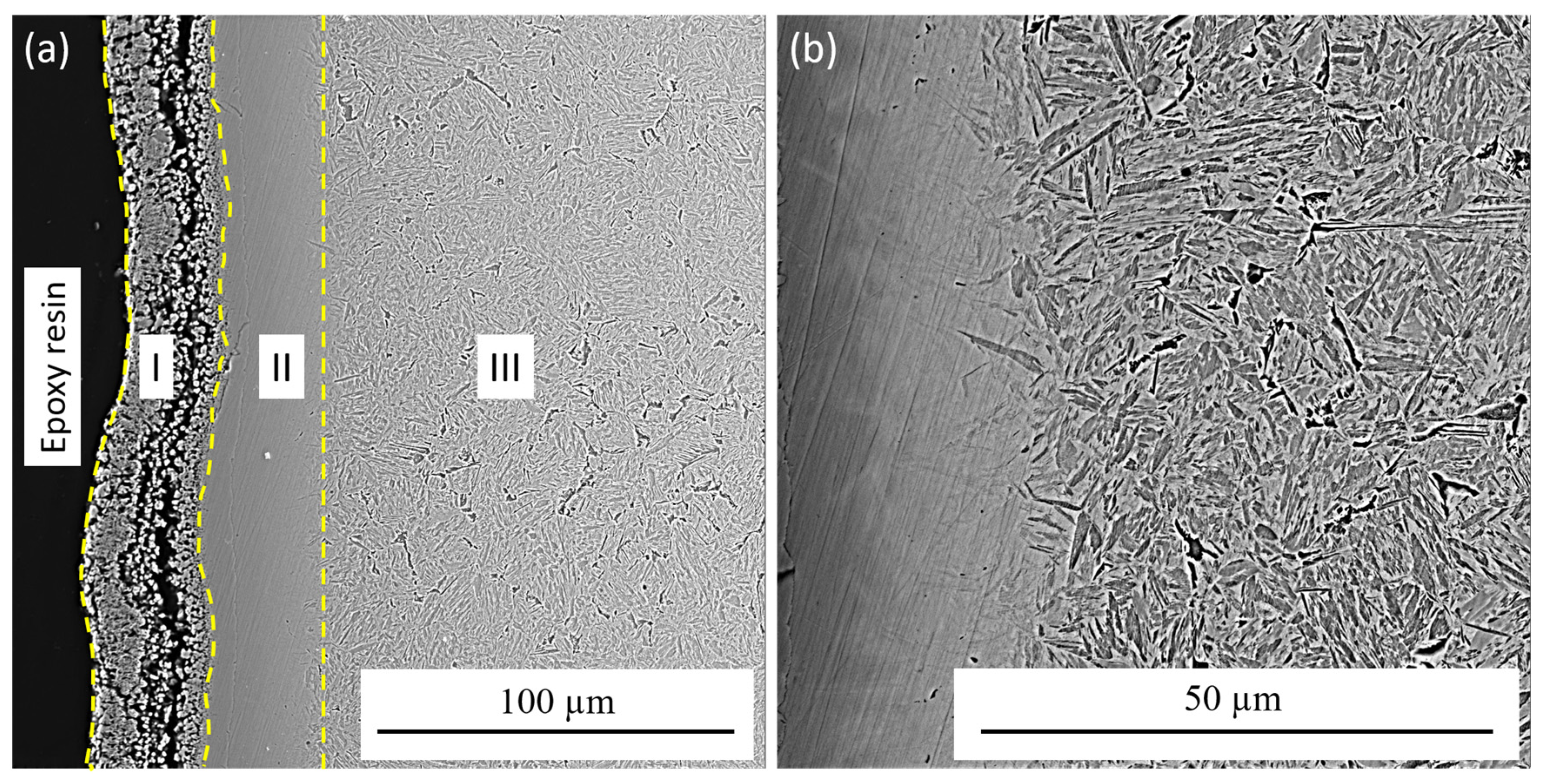
On the basis of metallographic and X-ray diffraction analyses, it was determined that after electrolyte–plasma nitriding, multilayer diffusion layers are formed. In the surface layer, the formed oxide–nitride zone 25–30 μm thick, containing iron nitride Fe2N and iron oxide Fe3O4. Under this zone is located a nitride–martensitic sublayer. This is followed by the third zone of internal nitriding.
-
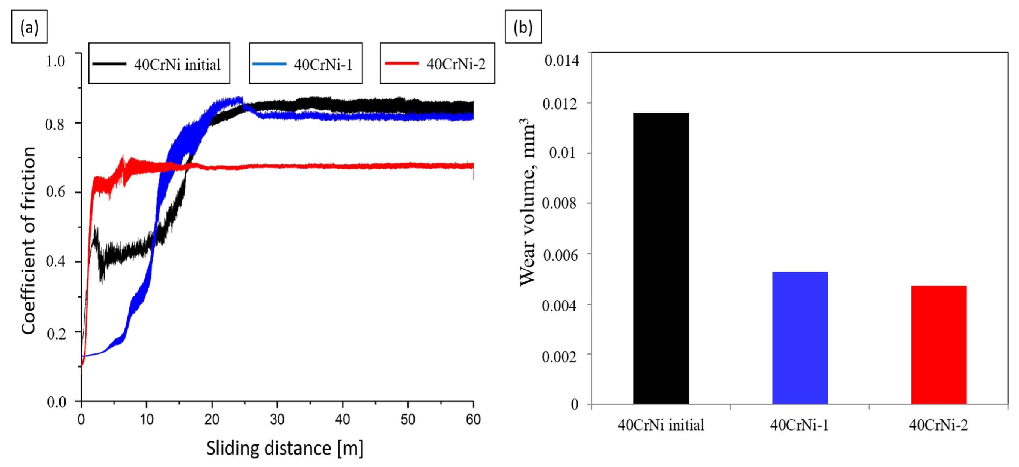
Tribological tests showed that the hardened samples have high wear resistance compared to the original samples. After nitriding steel in solutions of carbamide, the coefficient of dry friction decreases from 0.82 in the untreated sample to 0.63 in the sample after nitriding within 7 min, and the wear resistance increases by 1.5 times.
-
It is determined that after electrolyte–plasma nitriding, the surface hardness increases significantly. Nitriding regimes and the amount of alloying elements significantly affect the hardness of the diffusion zone.

Author Contributions

Conceptualization, B.R.; methodology, B.R.; investigation, Z.S., Z.T., N.B., D.B. and A.M.; data curation, D.B. and N.B.; writing—original draft preparation, B.R., Z.S. and D.B.; writing—review and editing, B.R., Z.S., D.B. and N.B.; supervision, B.R.; project administration, Z.S. All authors have read and agreed to the published version of the manuscript.

Funding

This research has been funded by the Science Committee of the Ministry of Science and Higher Education of the Republic of Kazakhstan (Grant no. AP14972599).

Data Availability Statement

The original contributions presented in the study are included in the article, further inquiries can be directed to the corresponding author/s.

Conflicts of Interest

Author Zarina Satbayeva and Zhangabay Turar were employed by the company “PlasmaScience” LLP. The remaining authors declare that the research was conducted in the absence of any commercial or financial relationships that could be construed as a potential conflict of interest.

References

  1. Belkin, P.N.; Kusmanov, S.A. Plasma electrolytic hardening of steels: Review. Surf. Eng. Appl. Electrochem. 2016, 52, 531–546. [Google Scholar] [CrossRef]
  2. Pantelis, D.I.; Bouyiouri, E.; Kouloumbi, N.; Vassiliou, P.; Koutsomichalis, A. Wear and corrosion resistance of laser surface hardened structural steel. Surf. Coat. Technol. 2002, 161, 125–134. [Google Scholar] [CrossRef]
  3. Kulka, M.; Pertek, A. Laser surface modification of carburized and borocarburized 15CrNi6 steel. Mater. Charact. 2007, 58, 461–470. [Google Scholar] [CrossRef]
  4. Hurtado-Delgado, E.; Huerta-Larumbe, L.; Miranda-Pérez, A.; Aguirre-Sánchez, Á. Microcracks reduction in laser hardened layers of ductile iron. Coatings 2021, 11, 3. [Google Scholar] [CrossRef]
  5. Rakhadilov, B.K.; Miniyazov, A.Z.; Skakov, M.K.; Sagdoldina, Z.B.; Tulenbergenov, T.R.; Sapataev, E.E. Structural modification and erosion of plasma-irradiated tungsten and molybdenum surfaces. Technol. Phys. 2020, 65, 382–391. [Google Scholar] [CrossRef]
  6. Zhu, X. Effect of fast cooling on mechanical properties of continuous annealed cold rolled ultra-high strength steel. Cailiao Rechuli Xuebao/Trans. Mater. Heat Treat. 2006, 27, 49–52. [Google Scholar]
  7. Tyurin, Y.N.; Pogrebnjak, A.D. Electric heating using a liquid electrode. Surf. Coat. Technol. 2001, 142–144, 293–299. [Google Scholar] [CrossRef]
  8. Ayday, A.; Durman, M. Effect of different surface-heat-treatment methods on the surface properties of AISI 4140 steel. Mater. Tehnol. 2014, 48, 787–790. [Google Scholar]
  9. Ayday, A.; Kırsever, D.; Demirkıran, A.Ş. The effects of overlapping in electrolytic plasma hardening on wear behavior of carbon steel. Trans. Indian Inst. Met. 2022, 75, 27–33. [Google Scholar] [CrossRef]
  10. Dyakov, I.G.; Burov, S.V.; Belkin, P.N.; Rozanov, E.V.; Zhukov, S.A. Increasing wear and corrosion resistance of tool steel by anodic plasma electrolytic nitriding. Surf. Coat. Technol. 2019, 362, 124–131. [Google Scholar] [CrossRef]
  11. Kusmanov, S.A.; Silkin, S.A.; Smirnov, A.A.; Belkin, P.N. Possibilities of increasing wear resistance of steel surface by plasma electrolytic treatment. Wear 2017, 386–387, 239–246. [Google Scholar] [CrossRef]
  12. Kumruoglu, L.C.; Becerik, D.A.; Ozel, A.; Mimaroglu, A. Surface modification of medium carbon steel by using electrolytic plasma thermocyclic treatment. Mater. Manuf. Process. 2009, 24, 781–785. [Google Scholar] [CrossRef]
  13. Tabiyeva, Y.Y.; Rakhadilov, B.K.; Uazyrkhanova, G.K.; Zhurerova, L.G.; Maulit, A.; Baizhan, D. Surface modification of steel mark 2 electrolytic plasma exposure. Eurasian J. Phys. Funct. Mater. 2019, 3, 355–362. [Google Scholar] [CrossRef]
  14. Belkin, P.N.; Kusmanov, S.A.; Parfenov, E.V. Mechanism and technological opportunity of plasma electrolytic polishing of metals and alloys surfaces. Appl. Surf. Sci. Adv. 2020, 1, 100016. [Google Scholar] [CrossRef]
  15. Bayati, M.R.; Molaei, R.; Janghorban, K. Surface alloying of carbon steels from electrolytic plasma. Met. Sci. Heat Treat. 2011, 53, 91–94. [Google Scholar] [CrossRef]
  16. Aliofkhazraei, M.; Taheri, P.; Rouhaghdam, A.S.; Dehghanian, C. Systematic study of nanocrystalline plasma electrolytic nitrocarburising of 316 L austenitic stainless steel for corrosion protection. J. Mater. Sci. Technol. 2007, 23, 665–671. [Google Scholar]
  17. Baizhan, D.; Rakhadilov, B.; Zhurerova, L.; Tyurin, Y.; Sagdoldina, Z.; Adilkanova, M.; Kozhanova, R. Investigation of Changes in the Structural-Phase State and the Efficiency of Hardening of 30CrMnSiA Steel by the Method of Electrolytic Plasma Thermocyclic Surface Treatment. Coatings 2022, 12, 1696. [Google Scholar] [CrossRef]
  18. Mukhacheva, T.L.; Belkin, P.N.; Dyakov, I.G.; Kusmanov, S.A. Wear mechanism of medium carbon steel after its plasma electrolytic nitrocarburizing. Wear 2020, 462–463, 203516. [Google Scholar] [CrossRef]
  19. Mamaeva, A.; Kenzhegulov, A.; Panichkin, A.; Abdulvaliyev, R.; Fischer, D.; Bakhytuly, N.; Toiynbaeva, N. Influence of Current Duty Cycle and Voltage of Micro-Arc Oxidation on the Microstructure and Composition of Calcium Phosphate Coating. Coatings 2024, 14, 766. [Google Scholar] [CrossRef]
  20. Kusmanov, S.A.; Kusmanova, Y.V.; Naumov, A.R.; Belkin, P.N. Features of anode plasma electrolytic nitrocarburising of low carbon steel. Surf. Coat. Technol. 2015, 272, 149–157. [Google Scholar] [CrossRef]
  21. Rakhadilov, B.; Satbayeva, Z.; Baizhan, D. Effect of electrolytic-plasma surface strengthening on the structure and properties of steel 40 kHN. In Proceedings of the METAL 2019—28th International Conference on Metallurgy and Materials, Conference Proceedings, Brno, Czech Republic, 22–24 May 2019; pp. 950–955. [Google Scholar] [CrossRef]
  22. Tabieva, E.E.; Zhurerova, L.G.; Baizhan, D. Influence of electrolyte-plasma hardening technological parameters on the structure and properties of banding steel 2. Key Eng. Mater. 2020, 839, 57–62. [Google Scholar] [CrossRef]
  23. Lu, S.; Sun, X.; Zhang, B.; Wu, J. Review of Cathode Plasma Electrolysis Treatment: Progress, Applications, and Advancements in Metal Coating Preparation. Materials 2024, 17, 3929. [Google Scholar] [CrossRef]
  24. Li, H.; Zhao, G.; Yu, H.; Cheng, K.; Feng, X.; Liu, Y.; Zhou, J.; Bai, M.; Ni, F.; Wu, J.; et al. Low Current Density Cathode Plasma Electrolytic Deposition of Aluminum Alloy Based on a Bipolar Pulse Power Supply. Coatings 2024, 14, 835. [Google Scholar] [CrossRef]
  25. Li, Y.; Zhou, Z.; He, Y. Solid Lubrication System and Its Plasma Surface Engineering: A Review. Lubricants 2023, 11, 473. [Google Scholar] [CrossRef]
  26. Kusmanov, S.; Mukhacheva, T.; Tambovskiy, I.; Naumov, A.; Belov, R.; Sokova, E.; Kusmanova, I. Increasing Hardness and Wear Resistance of Austenitic Stainless-Steel Surface by Anodic Plasma Electrolytic Treatment. Metals 2023, 13, 872. [Google Scholar] [CrossRef]
  27. Pérez, H.; Vargas, G.; Magdaleno, C.; Silva, R. Article: Oxy-Nitriding AISI 304 Stainless Steel by Plasma Electrolytic Surface Saturation to Increase Wear Resistance. Metals 2023, 13, 309. [Google Scholar] [CrossRef]
  28. Kim, Y.-S.; Choi, J.-Y.; Kim, C.-H.; Lee, I.-S.; Jun, S.; Kim, D.; Cha, B.-C.; Kim, D.-W. N+-Implantation on Nb Coating as Protective Layer for Metal Bipolar Plate in PEMFCs and Their Electrochemical Characteristics. Materials 2022, 15, 8612. [Google Scholar] [CrossRef]
  29. Bakhtiari-Zamani, H.; Saebnoori, E.; Bakhsheshi-Rad, H.R.; Berto, F. Corrosion and Wear Behavior of TiO2/TiN Duplex Coatings on Titanium by Plasma Electrolytic Oxidation and Gas Nitriding. Materials 2022, 15, 8300. [Google Scholar] [CrossRef]
  30. Rakhadilov, B.K.; Kurbanbekov, S.R.; Kilishkhanov, M.K.; Kenesbekov, A.B.; Amanzholov, S. Changing the structure and phasestates and the microhardness of the R6M5 steel surface layer after electrolytic-plasma nitriding. Eurasian J. Phys. Funct. Mater. 2018, 2, 259–266. [Google Scholar] [CrossRef]
Figure 1. Scheme of electrolytic plasma nitriding: (a) scheme of the electrolytic cell; (b) general scheme of the installation: 1—power source, 2—electrolytic cell, 3—sample fixing device, 4—bath, 5—electrolyte supply regulator, 6—pump.
Crystals 14 00759 g001
Figure 2. Diffractograms of (a) 40CrNi initial steel and nitrided layer (b) 40CrNi-1 and (c) 40CrNi-2 after EPN.
Crystals 14 00759 g002
Figure 3. Cross-sectional microstructure of sample 40CrNi-1 (a) ×1500: I—oxide layer; II—outer part of the nitride–martensitic layer; III—inner part of the nitride–martensitic layer; (b) ×4500.
Crystals 14 00759 g003
Figure 4. Microstructure of the cross-section of the sample 40CrNi-2: (a) ×1500: I—oxide-nitride layer; II—outer part of the nitride-martensitic layer; III—inner part of the nitride–martensitic layer; (b) ×4500.
Crystals 14 00759 g004
Figure 5. EDS analysis of 40CrNi-2 sample.
Crystals 14 00759 g005
Figure 6. Tribological characteristics: (a) Friction coefficient of 40CrNi steel before and after electrolytic plasma nitriding; (b) Wear volume of samples before and after electrolytic plasma nitriding.
Crystals 14 00759 g006
Figure 7. Hardness distribution over the thickness of the nitrided layer.
Crystals 14 00759 g007
Table 1. Electrolyte composition.
SampleElectrolyte CompositionPressuresTime
40CrNi-17% ammonium chloride (NH4Cl)
14% urea ((NH2)2CO)
7% sodium carbonate (Na2CO3)
72% distilled water (H2O)
320B
220B
7 s
7 min
40CrNi-210% sodium carbonate (Na2CO3)
20% urea ((NH2)2CO)
70% distilled water (H2O)
320B
220B
7 s
7 min
Table 2. XRD data.
Table 2. XRD data.
SampleDetected PhasesPhase Content, Mas. %Lattice Parameters, Å
40CrNi initialFe_229_BCC100a = 2.8690
40CrNi-1Fe_229_BCC91a = 2.8688
Fe2N_164_trigonal9a = 2.6648
c = 4.3371
40CrNi-2Fe2N_164_trigonal30a = 2.6650
c = 4.3369
Fe2N_60_orthorombic50a = 4.3200
b = 5.5793
c = 4.6916
Fe3O4_166_rhombohedral20a = 5.8514
c = 14.5110
Disclaimer/Publisher’s Note: The statements, opinions and data contained in all publications are solely those of the individual author(s) and contributor(s) and not of MDPI and/or the editor(s). MDPI and/or the editor(s) disclaim responsibility for any injury to people or property resulting from any ideas, methods, instructions or products referred to in the content.

