
Cutting Force Model of Ultrasonic Elliptical Vibration-Assisted Helical Milling of SiCp/Al Composites

Abstract
:1. Introduction
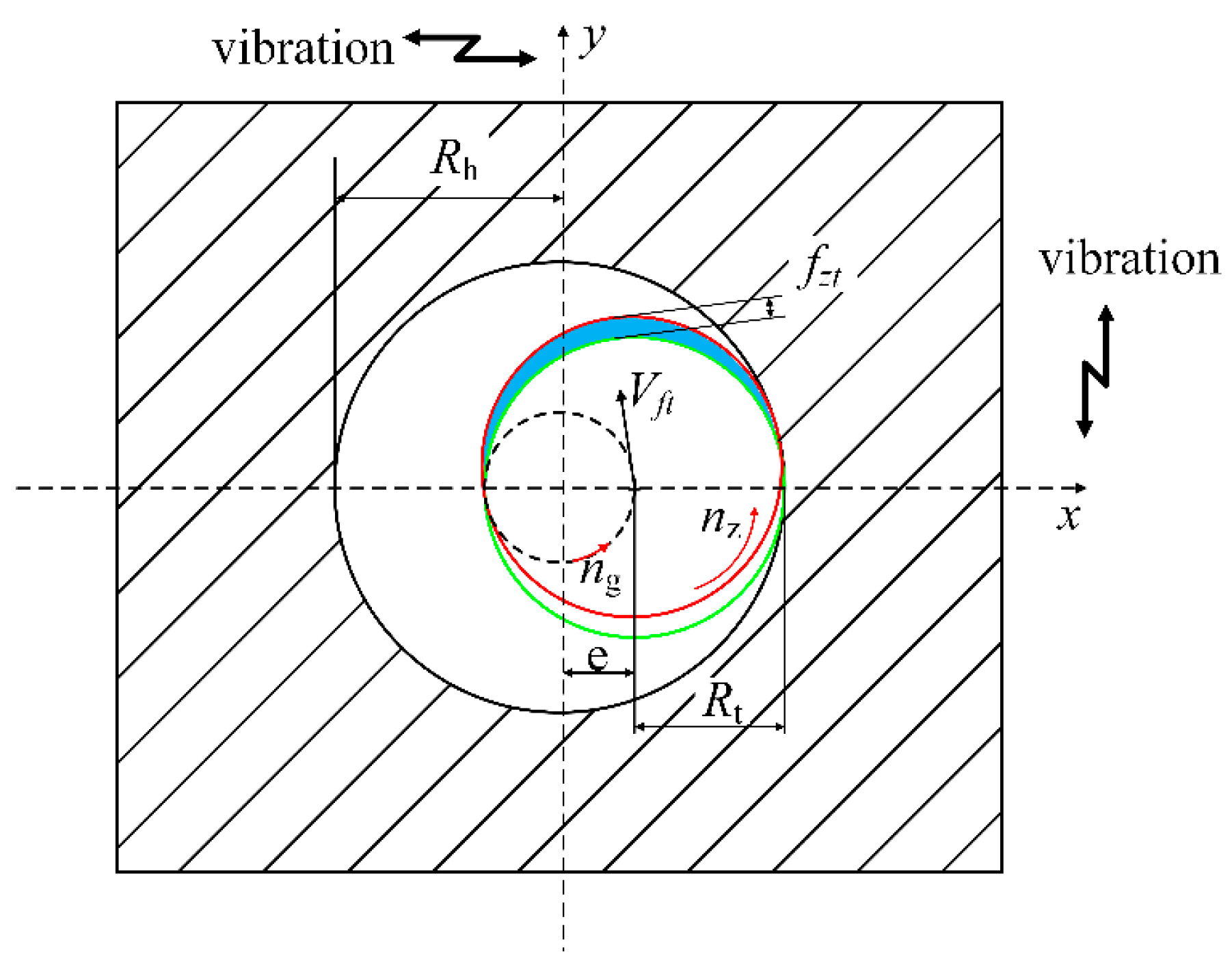
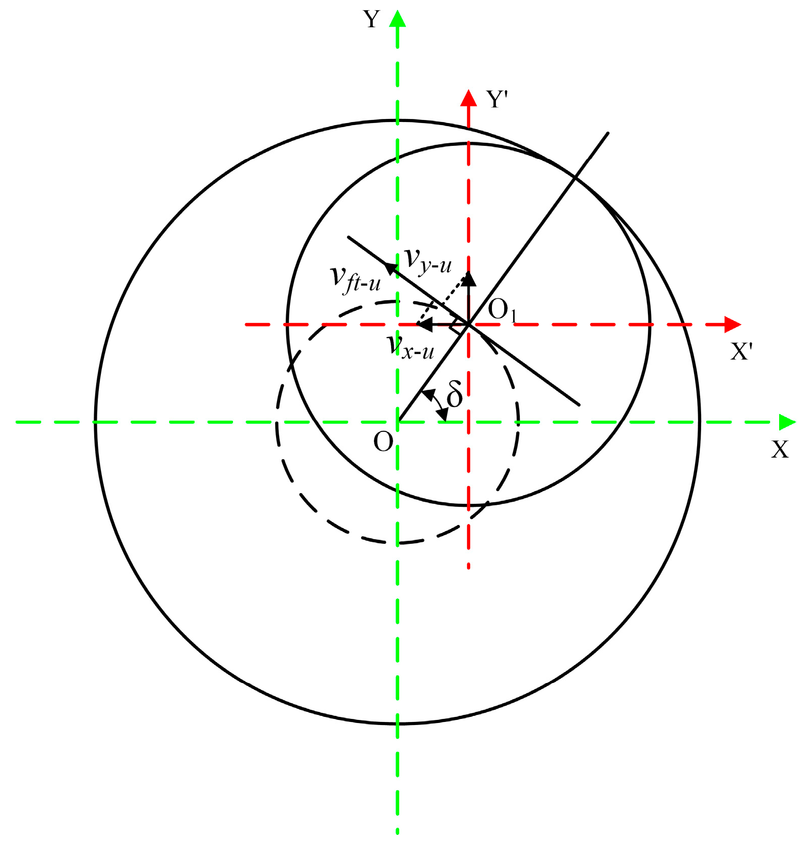
2. Kinetic Analysis
3. Cutting Force Model
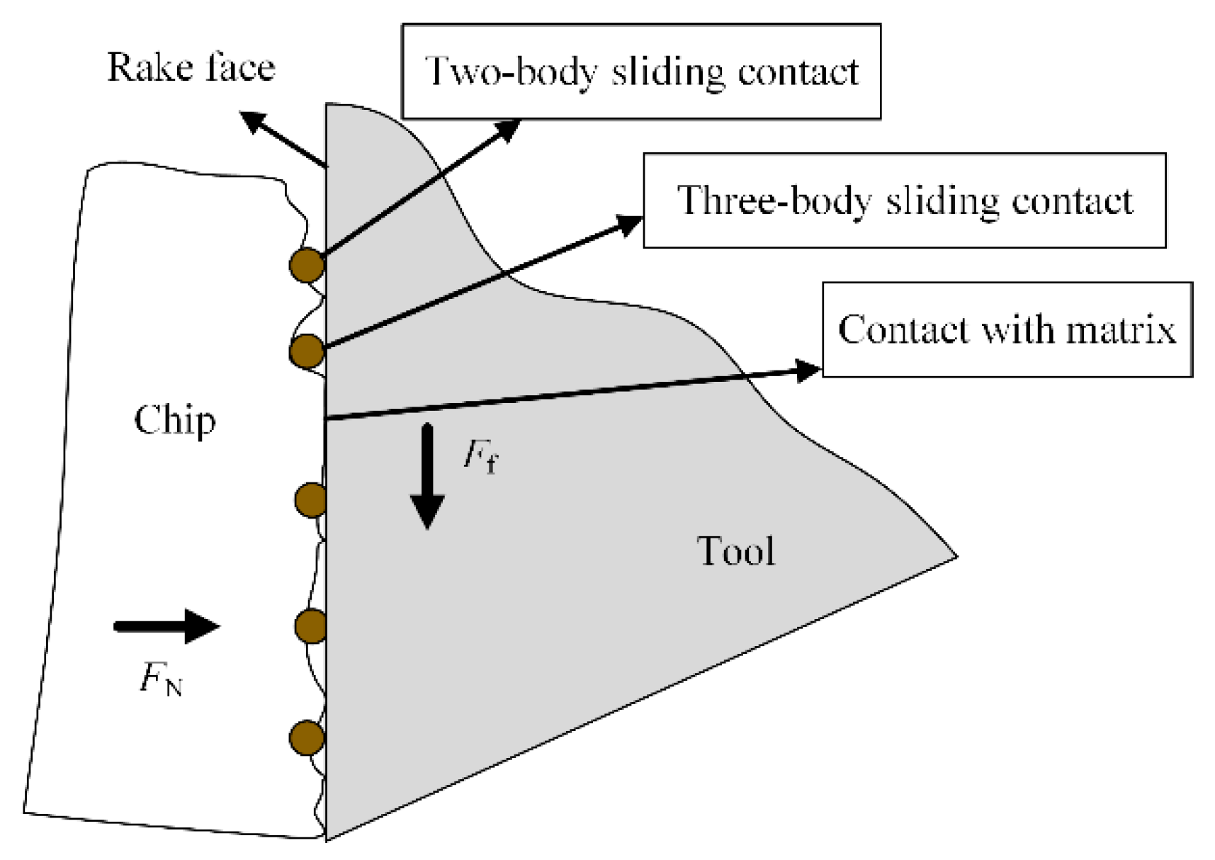
3.1. Force on the Tool Rake Face
3.1.1. Sliding Friction between the Rake Face and Matrix
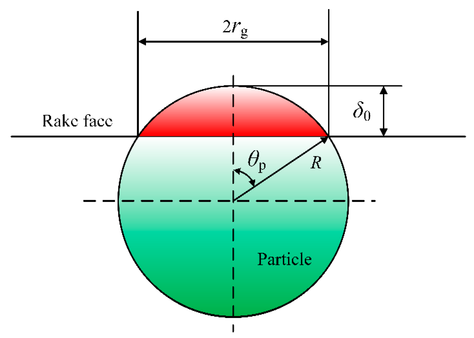
3.1.2. Sliding Friction between the Rake Face and Particle
3.1.3. Three-Body Rolling Friction of the Rake Face, Chip, and Particle
3.2. Force on the Cutting Edge
3.3. Force on the Tool Flank Face
3.4. Radial and Axial Forces
4. Experimental Procedures
5. Results and Discussion
6. Conclusions
- (1)
- The cutting edge motion trajectory model of UEVHM was established, and the comparison of the motion trajectories of HM and UEVHM revealed that UEVHM could realize intermittent cutting. In addition, a theoretical model of the maximum undeformed cutting thickness for spiral milling considering the effect of ultrasonic elliptical vibration was established.
- (2)
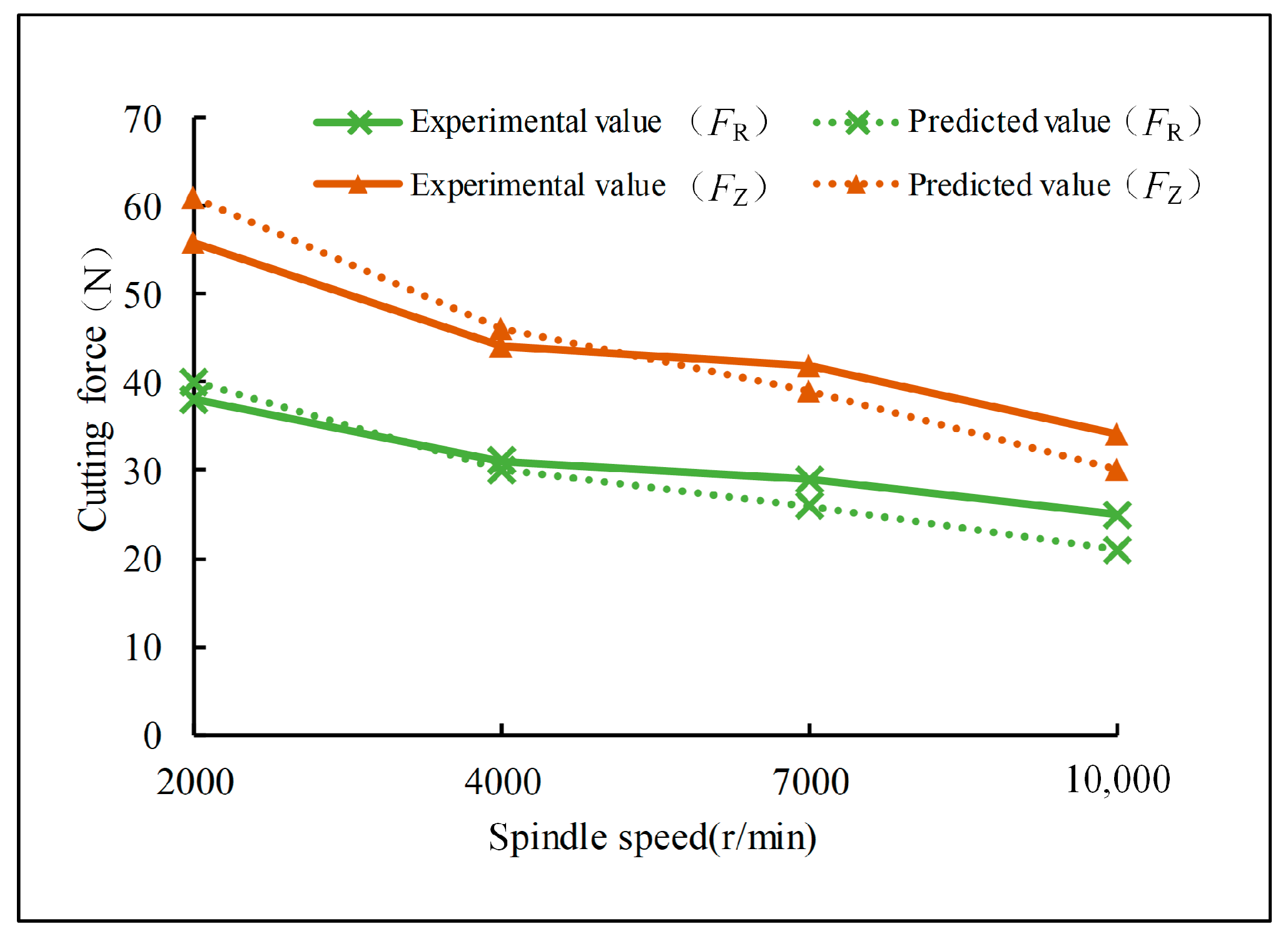
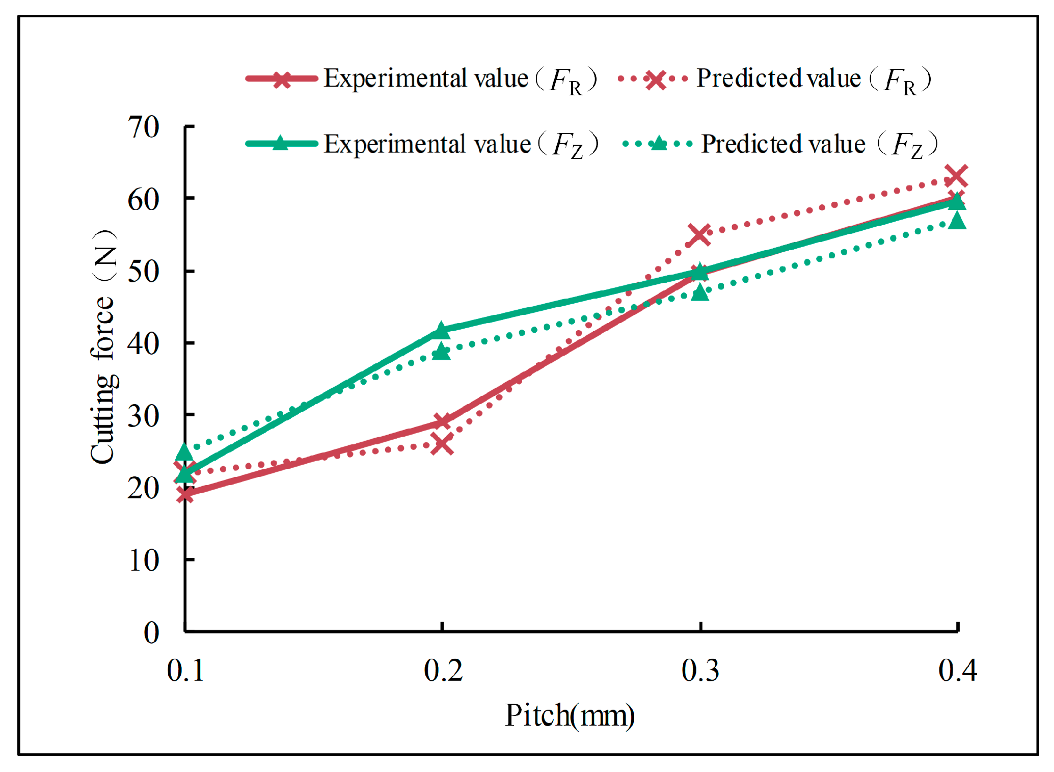
- An axial and radial helical milling force model that considers the three removal methods of particles and the effect of SiC particles on the friction of the front face, as well as the rebound force of the back face, was developed. The accuracy of the axial and radial force model was verified by tests, and the results showed that the model had a good accuracy with a maximum error of 19.06%.
- (3)
- The ultrasonic elliptical vibration helical milling force increases with an increase in the spindle speed and decreases with increases in the pitch and revolution speed. The change in pitch has the most obvious influence on the cutting force. A larger cutting speed has no obvious effect on reducing the cutting force. Therefore, the revolution speed can be appropriately increased in the UEVHM process, which can improve the processing efficiency while maintaining a small cutting force.
Author Contributions
Funding
Data Availability Statement
Conflicts of Interest
References
- Gao, H.T.; Liu, X.H.; Qi, J.L.; Chen, J.; Ai, Z. Strengthening mechanism of surface-modified SiCp/Al composites processed by the powder-in-tube method. Ceram. Int. 2019, 45, 22402–22408. [Google Scholar] [CrossRef]
- Zhu, C.; Gu, P.; Liu, D.; Hu, X.; Wu, Y. Evaluation of surface topography of SiCp/Al composite in grinding. Int. J. Adv. Manuf. Technol. 2019, 102, 2807–2821. [Google Scholar] [CrossRef]
- Davim, J.P.; Silva, J.; Baptista, A.M. Experimental cutting model of metal matrix composites (MMCs). J. Mater. Process. Technol. 2007, 183, 358–362. [Google Scholar] [CrossRef]
- Wu, G.; Kuang, Z. Opportunities and challenges for metal matrix composites in the context of equipment upgrading. Strateg. Study Chin. Acad. Eng. 2020, 22, 79–90. [Google Scholar] [CrossRef]
- Zheng, W.; Wang, Y.; Zhou, M.; Wang, Q.; Ling, L. Material deformation and removal mechanism of SiCp/Al composites in ultrasonic vibration assisted scratch test. Ceram. Int. 2018, 44, 15133–15144. [Google Scholar] [CrossRef]
- Zha, H.; Feng, P.; Zhang, J.; Yu, D.; Wu, Z. Material removal mechanism in rotary ultrasonic machining of high-volume fraction SiCp/Al composites. Int. J. Adv. Manuf. Technol. 2018, 97, 2099–2109. [Google Scholar] [CrossRef]
- Li, Q.; Yuan, S.; Gao, X.; Zhang, Z.; Chen, B.; Li, Z.; Batako, A.D. Surface and subsurface formation mechanism of SiCp/Al composites under ultrasonic scratching. Ceram. Int. 2023, 49, 817–833. [Google Scholar] [CrossRef]
- Wang, Z.; He, Y.; Yu, T. Surface quality and milling force of SiCp/Al ceramic for ultrasonic vibration-assisted milling. Ceram. Int. 2022, 48, 33819–33834. [Google Scholar] [CrossRef]
- Du, Y.; Lu, M.; Lin, J.; Yang, Y. Experimental and simulation study of ultrasonic elliptical vibration cutting SiCp/Al composites: Chip formation and surface integrity study. J. Mater. Res. Technol. 2023, 22, 1595–1609. [Google Scholar] [CrossRef]
- Haiyan, W.; Xuda, Q.; Hao, L.; Chengzu, R. Analysis of cutting forces in helical milling of carbon fiber–reinforced plastics. Proc. Inst. Mech. Eng. Part B J. Eng. Manuf. 2013, 227, 62–74. [Google Scholar] [CrossRef]
- Su, C.; Cheng, X.; Yan, X.; Zheng, G.; Li, Y.; Mu, Z. Helical milling for making holes on carbon fiber-reinforced polymer. Int. J. Adv. Manuf. Technol. 2022, 121, 5197–5205. [Google Scholar] [CrossRef]
- Wang, H.; Qin, X.; Ren, C.; Wang, Q. Prediction of cutting forces in helical milling process. Int. J. Adv. Manuf. Technol. 2012, 58, 849–859. [Google Scholar] [CrossRef]
- Sun, L.; Gao, H.; Wang, B.; Bao, Y.; Wang, M.; Ma, S. Mechanism of reduction of damage during helical milling of titanium/CFRP/aluminium stacks. Int. J. Adv. Manuf. Technol. 2020, 107, 4741–4753. [Google Scholar] [CrossRef]
- Tian, Y.; Liu, Y.; Wang, F.; Jing, X.; Zhang, D.; Liu, X. Modeling and analyses of helical milling process. Int. J. Adv. Manuf. Technol. 2017, 90, 1003–1022. [Google Scholar] [CrossRef]
- Liu, J.; Chen, G.; Ren, C.; Qin, X.; Zou, Y.; Ge, J. Effects of axial and longitudinal-torsional vibration on fiber removal in ultrasonic vibration helical milling of CFRP composites. J. Manuf. Process. 2020, 58, 868–883. [Google Scholar] [CrossRef]
- Chen, G.; Zou, Y.; Qin, X.; Liu, J.; Feng, Q.; Ren, C. Geometrical texture and surface integrity in helical milling and ultrasonic vibration helical milling of Ti-6Al-4V alloy. J. Mater. Process. Technol. 2020, 278, 116494. [Google Scholar] [CrossRef]
- Liu, G.; Xiang, D.; Peng, P.; Li, Y.; Yuan, Z.; Zhang, Z.; Gao, G.; Zhao, B. Establishment of scratching force model for micro-removal of SiCp/Al composites by ultrasonic vibration. J. Mater. Process. Technol. 2022, 307, 117677. [Google Scholar] [CrossRef]
- Wang, J.; Zuo, J.; Shang, Z.; Fan, X. Modeling of cutting force prediction in machining high-volume SiCp/Al composites. Appl. Math. Model. 2019, 70, 1–17. [Google Scholar] [CrossRef]
- Chang, L.; Weiwei, X.; Yan, J.; Xiaogeng, J.; Tao, Y. Mechanistic force modeling in drilling of SiCp/Al matrix composites considering a comprehensive abrasive particle model. Int. J. Adv. Manuf. Technol. 2020, 109, 421–442. [Google Scholar] [CrossRef]
- Lu, S.; Gao, H.; Bao, Y.; Xu, Q. A model for force prediction in grinding holes of SiCp/Al composites. Int. J. Mech. Sci. 2019, 160, 1–14. [Google Scholar] [CrossRef]
- Duan, C.; Sun, W.; Fu, C.; Zhang, F. Modeling and simulation of tool-chip interface friction in cutting Al/SiCp composites based on a three-phase friction model. International J. Mech. Sci. 2018, 142, 384–396. [Google Scholar] [CrossRef]
- Kishawy, H.A.; Kannan, S.; Balazinski, M. An energy based analytical force model for orthogonal cutting of metal matrix composites. CIRP Ann. 2004, 53, 91–94. [Google Scholar] [CrossRef]
- Zhao, G.; Xin, L.; Li, L.; Zhang, Y.; He, N.; Hansen, H.N. Cutting force model and damage formation mechanism in milling of 70wt% Si/Al composite. Chin. J. Aeronaut. 2023, 36, 114–128. [Google Scholar] [CrossRef]


| Test Number | Spindle Speed (r/min) | Pitch (mm) | Revolution Speed (r/min) | X Amplitude (μm) | Y Amplitude (μm) |
|---|---|---|---|---|---|
| 1 | 2000 | 0.2 | 50 | 4 | 4 |
| 2 | 5000 | 0.2 | 50 | 4 | 4 |
| 3 | 7000 | 0.2 | 50 | 4 | 4 |
| 4 | 10,000 | 0.2 | 50 | 4 | 4 |
| 5 | 7000 | 0.1 | 50 | 4 | 4 |
| 6 | 7000 | 0.3 | 50 | 4 | 4 |
| 7 | 7000 | 0.4 | 50 | 4 | 4 |
| 8 | 7000 | 0.2 | 30 | 4 | 4 |
| 9 | 7000 | 0.2 | 40 | 4 | 4 |
| 10 | 7000 | 0.2 | 60 | 4 | 4 |
| No. | Spindle Speed (r/min) | Pitch (mm) | Revolut-ion Speed (r/min) | FR (N) | FZ (N) | Error (%) | |||
|---|---|---|---|---|---|---|---|---|---|
| Predicted Value | Experime-ntal Value | Predicted Value | Experime-ntal Value | FR | FZ | ||||
| 1 | 2000 | 0.2 | 50 | 38.14 | 40.22 | 55.91 | 61.21 | −5.17 | −8.66 |
| 2 | 5000 | 0.2 | 50 | 31.95 | 30.36 | 44.15 | 46.22 | 5.23 | −4.48 |
| 3 | 7000 | 0.2 | 50 | 28.98 | 26.41 | 41.84 | 39.21 | 9.73 | 6.71 |
| 4 | 10,000 | 0.2 | 50 | 25.25 | 21.71 | 34.04 | 30.23 | 16.3 | 12.6 |
| 5 | 7000 | 0.1 | 50 | 19.64 | 22.36 | 22.08 | 25.74 | −12.16 | −14.2 |
| 6 | 7000 | 0.3 | 50 | 49.64 | 55.65 | 50.11 | 47.21 | −10.80 | 6.14 |
| 7 | 7000 | 0.4 | 50 | 60.12 | 63.82 | 59.75 | 57.03 | −5.80 | 4.77 |
| 8 | 7000 | 0.2 | 30 | 23.74 | 19.94 | 32.84 | 29.71 | 19.06 | 10.54 |
| 9 | 7000 | 0.2 | 40 | 26.32 | 22.98 | 39.06 | 34.16 | 14.53 | 14.34 |
| 10 | 7000 | 0.2 | 60 | 31.13 | 36.20 | 56.17 | 48.19 | −14.00 | 16.56 |
Disclaimer/Publisher’s Note: The statements, opinions and data contained in all publications are solely those of the individual author(s) and contributor(s) and not of MDPI and/or the editor(s). MDPI and/or the editor(s) disclaim responsibility for any injury to people or property resulting from any ideas, methods, instructions or products referred to in the content. |
© 2024 by the authors. Licensee MDPI, Basel, Switzerland. This article is an open access article distributed under the terms and conditions of the Creative Commons Attribution (CC BY) license (https://creativecommons.org/licenses/by/4.0/).
Share and Cite
Liu, J.; Zhou, Y.; Jia, S.; Lu, Y.; Zheng, H.; Li, M. Cutting Force Model of Ultrasonic Elliptical Vibration-Assisted Helical Milling of SiCp/Al Composites. Crystals 2024, 14, 774. https://doi.org/10.3390/cryst14090774
Liu J, Zhou Y, Jia S, Lu Y, Zheng H, Li M. Cutting Force Model of Ultrasonic Elliptical Vibration-Assisted Helical Milling of SiCp/Al Composites. Crystals. 2024; 14(9):774. https://doi.org/10.3390/cryst14090774
Chicago/Turabian StyleLiu, Ji, Yunguang Zhou, Shiqi Jia, Yize Lu, Hui Zheng, and Ming Li. 2024. "Cutting Force Model of Ultrasonic Elliptical Vibration-Assisted Helical Milling of SiCp/Al Composites" Crystals 14, no. 9: 774. https://doi.org/10.3390/cryst14090774