Abstract
Spent selective catalytic reduction (SCR) catalysts are hazardous wastes containing many valuable metals whose improper disposal can cause environmental pollution and resource waste. Therefore, it is significant to recover valuable metals from spent SCR catalysts. In this study, the molten salt electrolytic method was employed to treat the SCR catalyst to direct electrosynthesis titanium alloys, which is more environmentally friendly and economical to obtain metal or alloy from secondary resources. A systematic investigation was carried out via experimental analysis and thermodynamic calculation. The results show that high-temperature pretreatment induces the aggregation of W and the formation of CaWO4. Through molten salt electrolysis, titanium alloys containing Ti(W) and Ti5Si3 were formed, with a metal recovery rate of 80–87%. The electrolytic process and the reaction mechanism were also investigated. It is suggested that the molten salt electrolytic method is an effective way to recover valuable metals from spent SCR catalysts.
1. Introduction
A large amount of NOx is emitted from thermal power plants and steel works, which leads to generating acid rain, the greenhouse effect, and photochemical smog. To reduce NOx emissions, selective catalytic reduction, as an effective technology, has been commonly employed in industry. Generally, the SCR catalyst of V2O5-WO3/TiO2 plays a key role in affecting the reduction [1]. However, the complex flue gas environment would cause SCR catalyst deactivation, such as catalyst blockage, catalyst wear, high-temperature sintering, and chemical poisoning [2]. The service life of the V2O5-WO3/TiO2 catalyst is usually three to five years. According to the statistics, 250,000–300,000 m3 of spent SCR catalysts are generated annually in China [3,4]. Spent V2O5-WO3/TiO2 catalysts are hazardous solid waste. If discarded randomly, it not only leads to serious environmental problems but also brings resource waste. Therefore, it is significant to recycle spent V2O5-WO3/TiO2 catalysts.
Spent V2O5-WO3/TiO2 catalysts contain many valuable metals, such as 80–85% TiO2, 5–7% WO3, and 0.7–1.5% V2O5, which can be a second source to recover [5,6,7]. So far, many recycling methods have been proposed for spent SCR catalysts, mainly divided into the hydrometallurgy method and the pyrometallurgy method. Hydrometallurgy methods have been commonly used to recycle valuable metals from spent SCR catalysts, including acid leaching, alkaline leaching, sodium roasting-leaching, and calcification roasting-leaching [3,7,8,9,10,11,12,13]. For acid leaching, inorganic acids and organic acid reagents were used to dispose of spent SCR catalysts, which makes the valuable metals transformed into acidic solutions. Wang et al. [9] investigated the acid system of H2SO4-ascorbic to recover V2O5 from spent SCR catalysts. The addition of ascorbic acid can raise the leaching rate of the vanadium in H2SO4. The effects of leaching temperature, acid concentration, liquid-solid (L/S) ratio, and leaching time were investigated. Alkaline leaching is usually employed as an alkali reagent to leach V and W, which has several advantages, such as higher leaching efficiency and lower costs. Liu et al. [8] utilized alkali pressure leaching to extract V and W from spent SCR catalysts. The leaching efficiency of V and W can reach 98.83% and 100% by adjusting reaction time, leaching temperature, NaOH concentration, and stirring speed. Also, anatase TiO2 can be reconstructed and recovered by the NaOH hydrothermal method [3]. The sodium roasting-leaching and calcification roasting-leaching methods mainly extract target metals by roasting the waste with Na2CO3, NaOH, CaO, or CaCO3 at high temperatures to be more effectively leaching. The effect of Na2CO3 addition, roasting time, and roasting temperature on the extraction efficiency of W and V was explored by Choi et al. [14]. It is shown that the addition of Na2CO3 plays a vital role. The increasing dosage of Na2CO3 can significantly increase the extraction efficiency of W. Yao et al. [15] employed a simple method of successive calcination-H2C2O4 leaching to recover the valuable metal W from spent V2O5-WO3/TiO2 catalysts. The leaching efficiency reaches 87%, and the purity of WO3 is 91%. Furthermore, the separation and purification of V and W from the leaching solution of spent V2O5-WO3/TiO2 catalysts are treated through chemical precipitation and ion exchange methods. Xiao et al. [16] utilized the primary amine N1923 to separate W and V from spent SCR catalyst solutions by anion exchange mechanism. Although the hydrometallurgy method is a common way to treat SCR catalysts, some issues still exist, such as the long process flow and the great environmental risks.
Pyrometallurgy is another method for the recovery of valuable metals from SCR catalysts, which is usually by adding reducing agents such as carbon, Mg, H2, and Al, and realized by thermal reduction [17,18,19]. Wang et al. [17] proposed an effective way to prepare V- and W-containing TiAl alloys by adding Al in spent SCR catalysts to reduce at 1600 °C. The influence factors of the reaction time, slag composition, and amount of reductant added to the recovery efficiency were explored. The maximum recovery efficiency is 98.14%, 94.16%, and 81.85% for V, Ti, and W, respectively. Li et al. [18,20] prepared Si–Ti alloy by reducing spent SCR catalyst with diamond-wire sawing silicon waste at 1500 °C. The pyrometallurgy method is indeed an environmentally friendly technology, but it has high energy consumption. So far, there is still no appropriate method to meet the demand. The new recycling method should be explored to recycle spent SCR catalysts.
Molten salt electrolysis is an effective and environmentally friendly method to treat solid waste. Compared with other methods, molten salt electrolysis was generally performed at low temperatures with low energy consumption, and no significant pollution was caused in the short process. The hydrometallurgy method generally has a long process flow and generates waste liquids that result in environmental problems, such as waste acid and alkali waste liquor. So far, many studies have been devoted to recycling valuable metals from solid waste using molten salt electrolysis. Lu et al. [21] present a solid-state electrolysis method in molten salts to effectively recycle aluminum scrap with low energy consumption. The electrochemical behavior of titanium-bearing slag in its molten state was investigated, and the Ir-Ti-Si alloy could be achieved by electrolysis [22]. Zhou et al. [23] treated high titanium slag and C through the molten salt electrolytic method to prepare TiC/SiC. Meanwhile, Ti5Si3, Ti5Si3/Ti3SiC2, and Ti5Si3/TiC can also be electro-synthesized from the Ti-bearing blast furnace slag in molten CaCl2 [24]. It is evident that molten salt electrolysis is an effective method to recycle titania-containing waste. Herein, molten salt electrolysis was employed to treat spent SCR catalyst to recover valuable metals. The present paper successfully uses molten salt electrolysis to prepare Ti(W) and Ti5Si3 alloys directly from spent SCR catalyst in molten CaCl2-NaCl electrolyte. The effects of high-temperature pretreatment and electrolyzing time were investigated. The electrolytic products at different conditions were characterized. Meanwhile, the electroreduction process and reaction mechanism were discussed based on the theoretical analysis and the experimental results. It is obvious that molten salt electrolysis provides a new direction for recycling spent SCR catalysts.
2. Experimental
2.1. Raw Materials and Characterization
The raw materials of spent commercial honeycomb SCR catalysts were collected from a thermal power plant in Hebei province, China. The spent SCR catalyst was first washed to remove the fly ash, then mashed by ball milling to prepare subsequent experiments. CaCl2 and NaCl with analytical grades were provided by the Beijing Chemical Industry.
The chemical compositions were characterized by an X-ray fluorescence spectrometer (XRF). The phase compositions were investigated by X-ray diffraction (XRD). The scanning electron microscope with X-ray energy dispersive spectroscopy (EDS) was performed to investigate the morphology and surface element distribution of samples. The experimental voltage was set to 3.2 V, and the current was tested by a HP34401A digital multimeter.
2.2. Experimental Methods
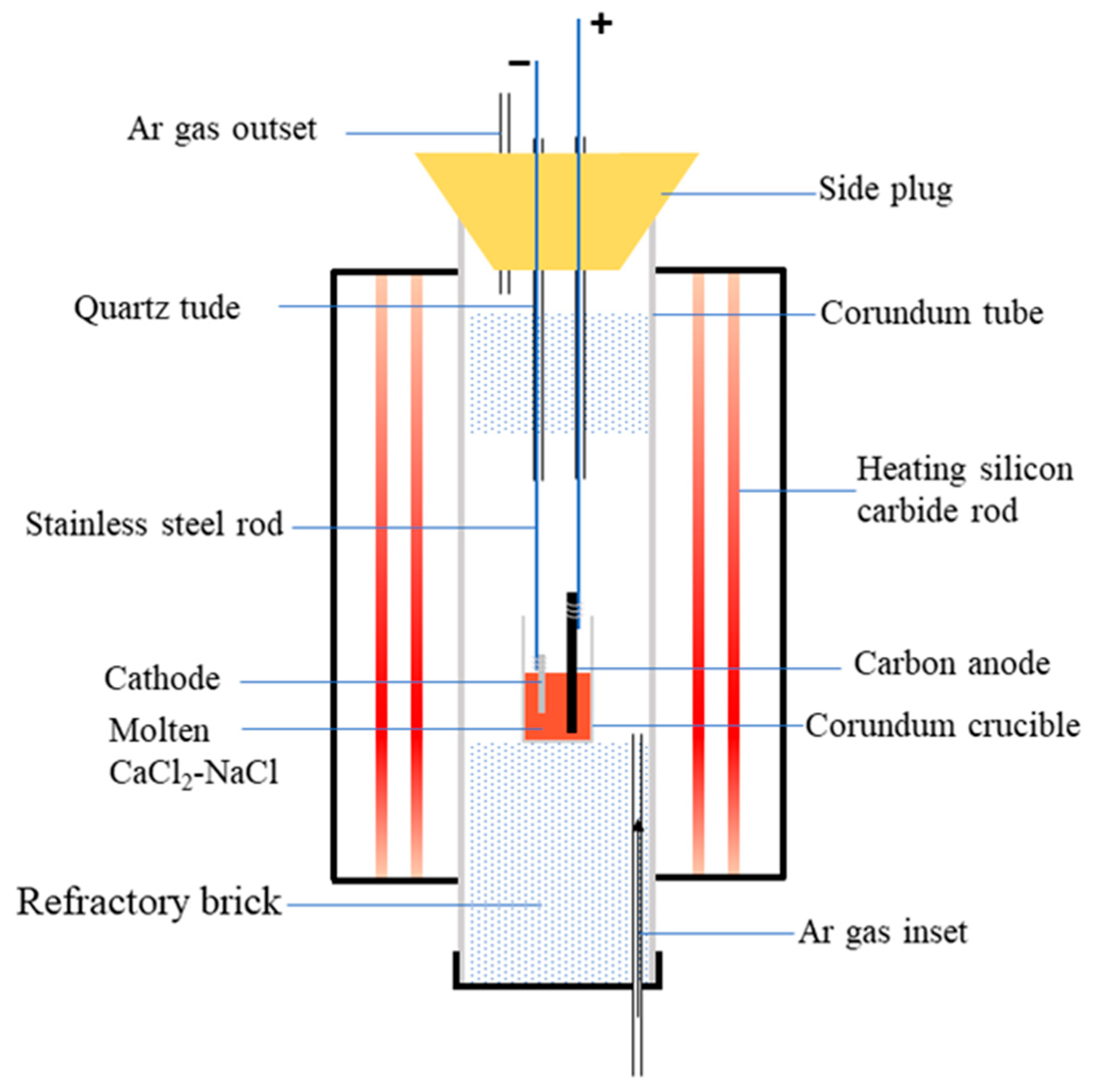
The spent SCR catalyst was pretreated at 1100 °C for 2 h. Then, the sintered sample was wrapped with iron mesh and bundled with stainless steel rods to serve as the cathode. The graphite electrode was employed as the anode during electrolysis. In addition, anhydrous CaCl2 and NaCl in a molar ratio of 0.52:0.48 was used as the molten salt electrolyte, and the electrolysis cell was an alumina crucible. The schematic diagram of the electrolytic device is shown in Figure 1. Before electrolysis, the furnace temperature reached 500 °C under a high-purity argon atmosphere to remove any water. Then, the electrolysis experiment was performed at 800 °C with 3.2 V. Subsequently, the electrolytic products were washed with distilled water to remove any residual electrolyte. Finally, the samples were dried at 120 °C for 2 h for subsequent tests. The electrolyzing conditions of 800 °C and 3.2 V were selected according to the previous literature: high temperature and high cell voltage can enhance the electroreduction-driven forces [25].

Figure 1.
Schematic diagram of electrolytic device.
3. Results and Discussion
3.1. Characterization of the Spent SCR Catalyst
The chemical compositions of the raw materials were characterized by XRF, as shown in Table 1. Table 1 presents that spent SCR catalyst mainly contains TiO2, WO3, SiO2, and CaO with higher weight ratios of 85.4%, 5.1%, 4.4%, and 1.4%, respectively. Further, the weight ratio of V2O5 is less than 1% with 0.9%, typical of an SCR catalyst. It also indicates that there are many valuable metals to recover. The morphology, elemental distribution, and phase composition were analyzed by SEM and XRD, as exhibited in Figure 2. From Figure 2a, it is obvious that the spent SCR catalyst powder presents flocculent with small particle size. Figure 2b–f show the elemental distribution of the spent SCR catalyst. The elemental mapping results reveal that the elements of Ti, O, and W display homogeneous distribution, while Ca and Si elements overlap, suggesting some Ca-Si-O compounds are generated. The EDS analysis result is shown in Figure 2g. It also can be seen that the main composition elements of the spent SCR catalyst are Ti, W, Si, and Ca, which agrees well with the XRF results. The main phase composition of the spent SCR catalyst is anatase-type TiO2, and there is no other obvious phase observed, as shown in Figure 2h, which may be owing to the low content and the dispersed distribution of W-O and Ca-Si-O compounds.

Table 1.
Chemical composition of spent SCR catalysts analyzed by XRF (wt%).
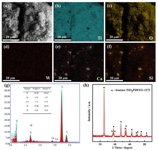
Figure 2.
SEM image (a), EDS mapping image (b–f), EDS analysis (g), and XRD patterns (h) of spent SCR catalyst.
3.2. Effects of High-Temperature Pretreatment
High-temperature pretreatment is an effective way to remove some impurities and improve electron transfer ability, which is beneficial for subsequent electrolysis. Table 2 shows the chemical composition of the spent SCR catalyst after high-temperature treatment for 2 h at 1100 °C, characterized by XRF. Compared with the raw materials of the spent SCR catalyst, it is evident that F and SO3 nearly disappeared after high-temperature treatment, indicating some impurities are indeed removed and reduce the effect on the subsequent electrolysis. The phase composition was also investigated by XRD, as exhibited in Figure 3. It is obvious that the main phase transforms from anatase-type TiO2 to rutile-type, and CaWO4 and SiO2 appear.
Table 2.
Chemical composition of spent SCR catalyst after high-temperature treatment (wt%).
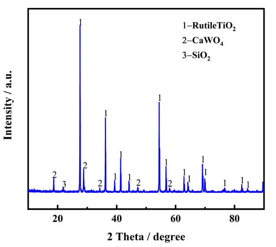
Figure 3.
XRD pattern of spent SCR catalyst after high-temperature treatment.
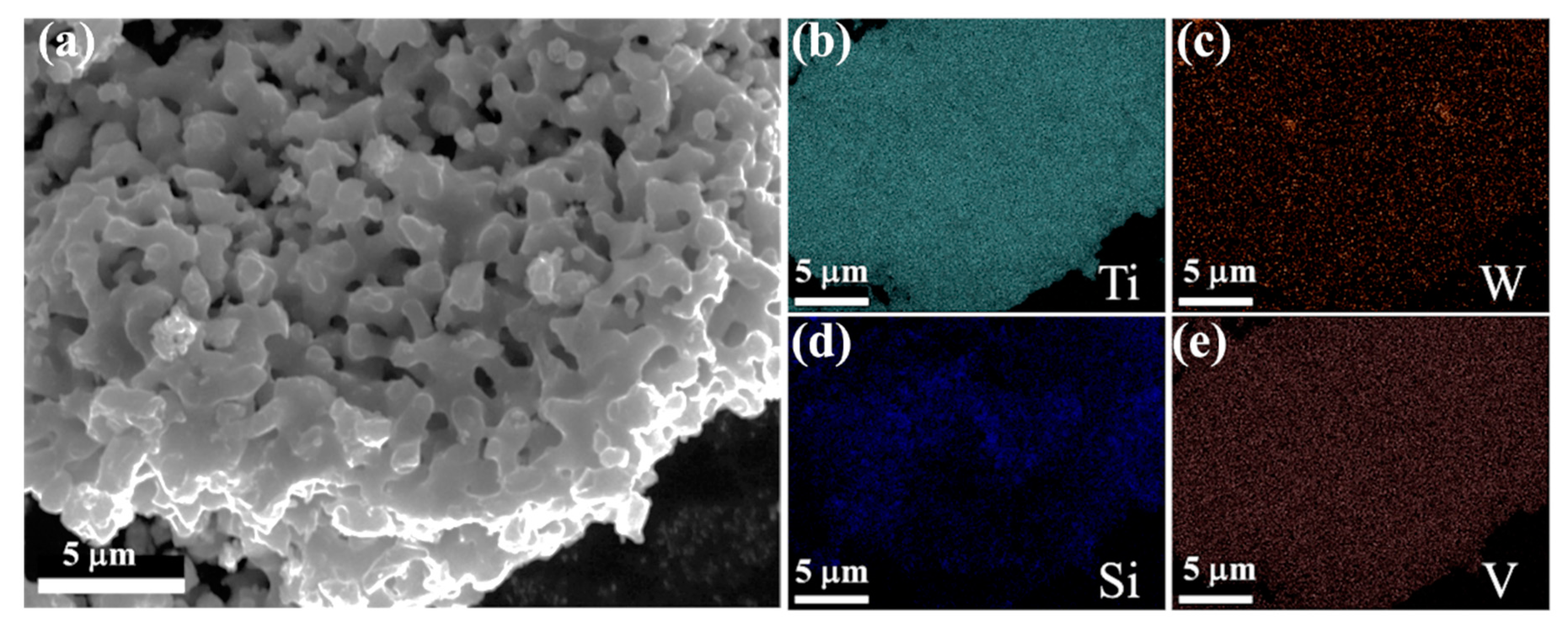
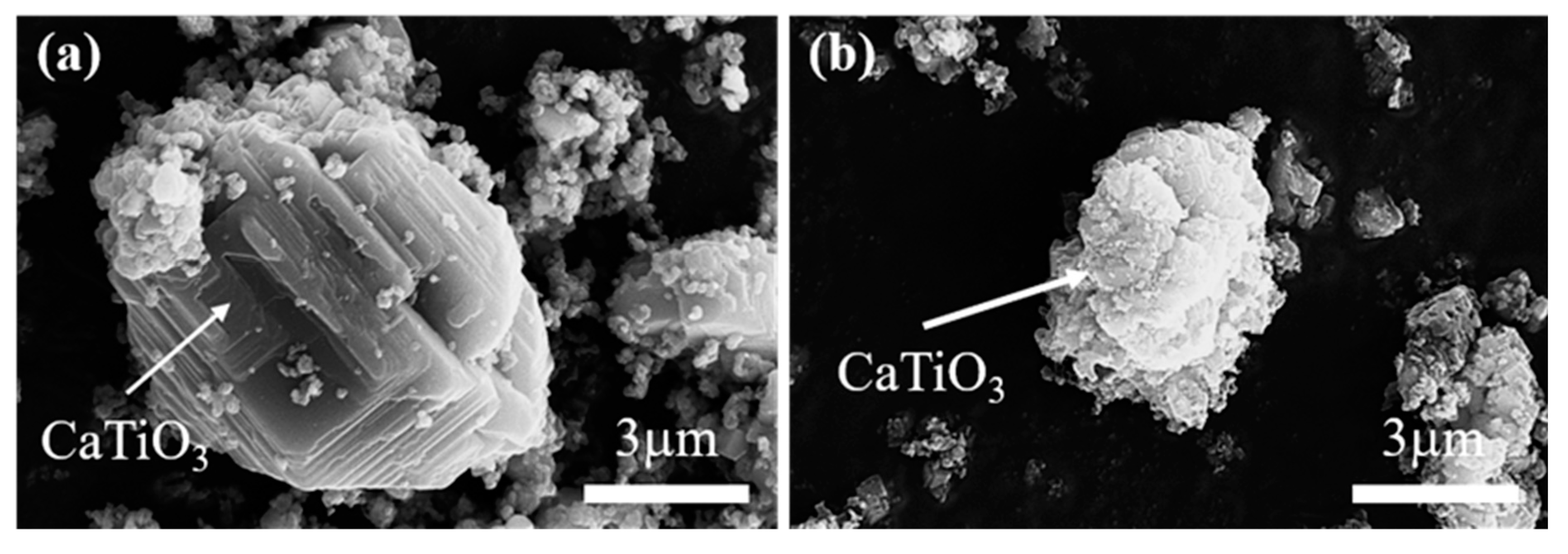
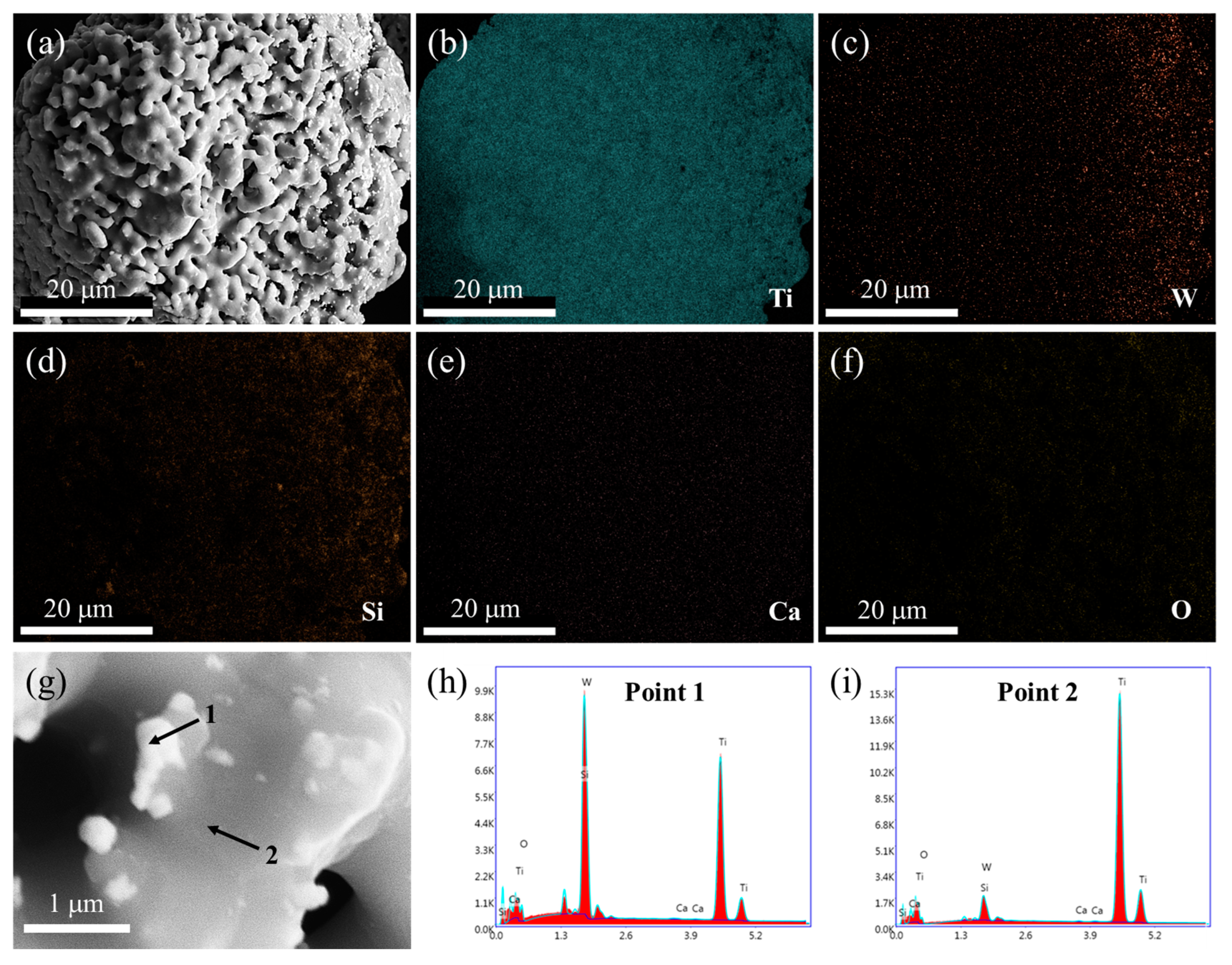
The morphology and the elemental distribution of the spent SCR catalyst after high-temperature treatment were investigated by SEM and EDS, as shown in Figure 4. After high-temperature treatment, the agglomeration and growth of particles are displayed, and the porous structure is increased, as exhibited in Figure 4a. From Figure 4b–f, it is obvious that Ti and O still distribute homogeneously, while W presents an aggregation with an apparent change, which overlaps with the elemental distribution of Ca. This agrees well with the XRD result of CaWO4 appearance. According to the enlarged SEM image and EDS spot analysis, it can be seen that TiO2 acts as matrix material with large and smooth morphology, where small particles of Ca(W, Ti)O4 are attached, which is consistent with the experimental results of Bhagat. et al. [26].

Figure 4.
SEM image (a), elemental mapping analysis (b–f), enlarged SEM image (g), and EDS spot analysis (h–i) of spent SCR catalyst after high-temperature treatment. The locations of 1 and 2 represent the EDS spots.
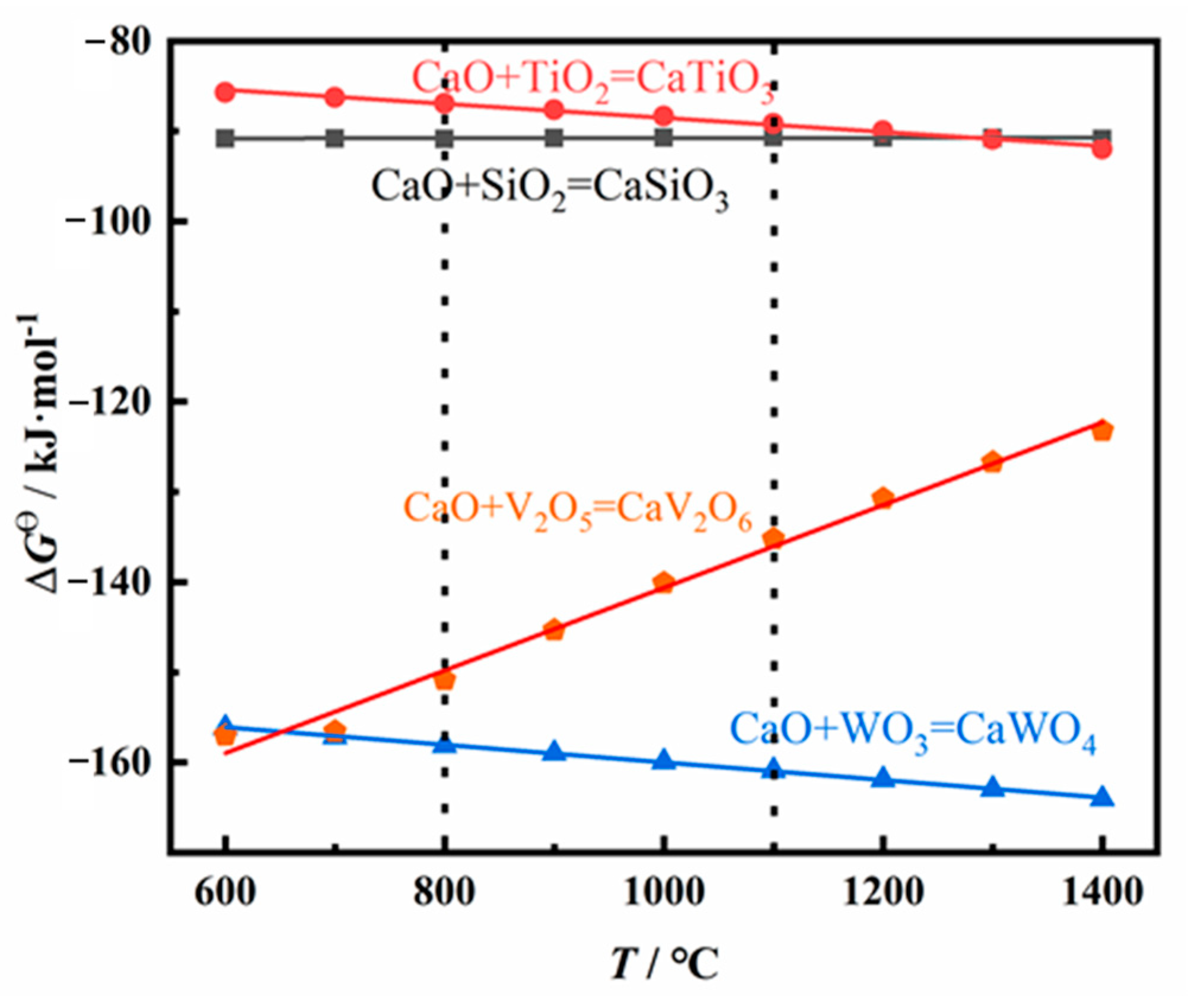
To clarify the reaction mechanism of the spent SCR catalysts in high-temperature pretreatment, the thermodynamic data was calculated, as exhibited in Figure 5. The standard Gibbs free energies (ΔGθ) of possible reactions of the spent SCR catalyst as a function of temperature are presented. A negative value of ΔGθ indicates the corresponding reaction may occur. The lower the value of ΔGθ is, the more energetically advantageous for the reaction to occur. All values of ΔGθ present negative above 600 °C, indicating CaTiO3, CaSiO3, CaV2O6, and CaWO4 may be formed at high temperatures. Among them, the ΔGθ of CaWO4 shows the lowest value at 1100 °C, indicating CaWO4 is first formed in theory. Meanwhile, considering the amount of CaO in the spent SCR catalyst, CaO mainly reacts with WO3 in high-temperature pretreatment, and no residual CaO reacts with SiO2 and TiO2. Therefore, the main phase compositions are TiO2, SiO2, and CaWO4 after high-temperature treatment. This is consistent with the XRD results, in which the phase compositions are TiO2, SiO2, and CaWO4.

Figure 5.
Theoretical calculation for the possible reaction of spent SCR catalyst at high temperature.
3.3. Electrolytic Products
The electrolytic product was obtained by the spent SCR catalyst electrolysis at 800 °C, 3.2 V, for 12 h. The phase compositions were analyzed by XRD, as presented in Figure 6. α-Ti and Ti5Si3 were formed after electrolysis, indicating the spent SCR catalyst totally transformed to titanium alloys via the electro-deoxidization method in molten salt of CaCl2-NaCl. Figure 7 exhibits the SEM image and element mapping images of the electrolytic product. The electrolytic product presents a network structure owing to the localized melting of the alloy, as shown in Figure 7a. From Figure 7b–e, the elements of Ti, W, and V have a uniform distribution, while Si shows aggregation. This reveals that W and V partially substitute Ti to form W- and V-containing α-Ti alloy, and the Ti5Si3 alloy is generated, which conforms to the XRD results. Meanwhile, the metal recovery rate was calculated, which is in the range of 80–87%. The electrolytic products of Ti(W) and Ti5Si3 can be used as raw materials to prepare titanium alloys. Meanwhile, the particle size of electrolytic products can be controlled by optimum electrolyzing conditions, which has a potential application in 3D printing. Furthermore, the electrolytic product can be carbonized to prepare high-temperature structural material or be used as reinforcement to improve the mechanical properties of metal matrix composites.
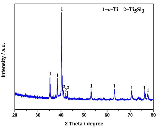
Figure 6.
XRD pattern of spent SCR catalyst after electrolysis.
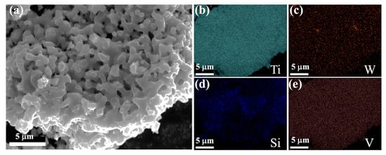
Figure 7.
SEM image (a) and element mapping images (b–e) of the electrolytic product.
3.4. Electroreduction Process
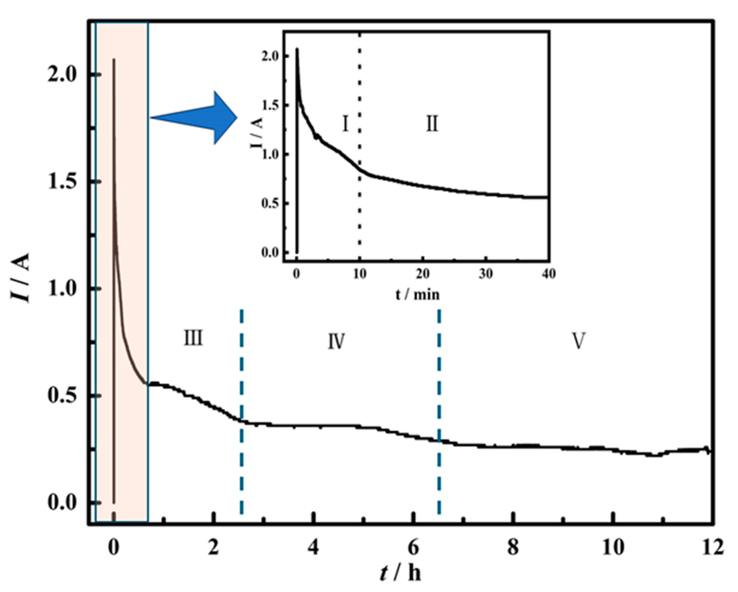
To investigate the process of electrochemical reduction, the electrochemical reaction in different stages was explored, as shown in Figure 8. Figure 8 exhibits the time-current plot of spent SCR catalyst electrolysis. The current decreases rapidly within 10 min and changes slightly in the time range of 10–40 min. After 40 min, the current decreases slowly. According to the changing trend of the curve, it can be divided into five stages. The electrochemical reduction at different stages was investigated by choosing different electrolytic durations of 10 min, 0.5 h, 1 h, 2 h, 4 h, 8 h, and 12 h, respectively.
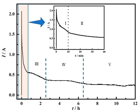
Figure 8.
Time-current curve of spent SCR catalyst electrolysis. I, II, III, IV and V represent different stages of electrochemical reduction.
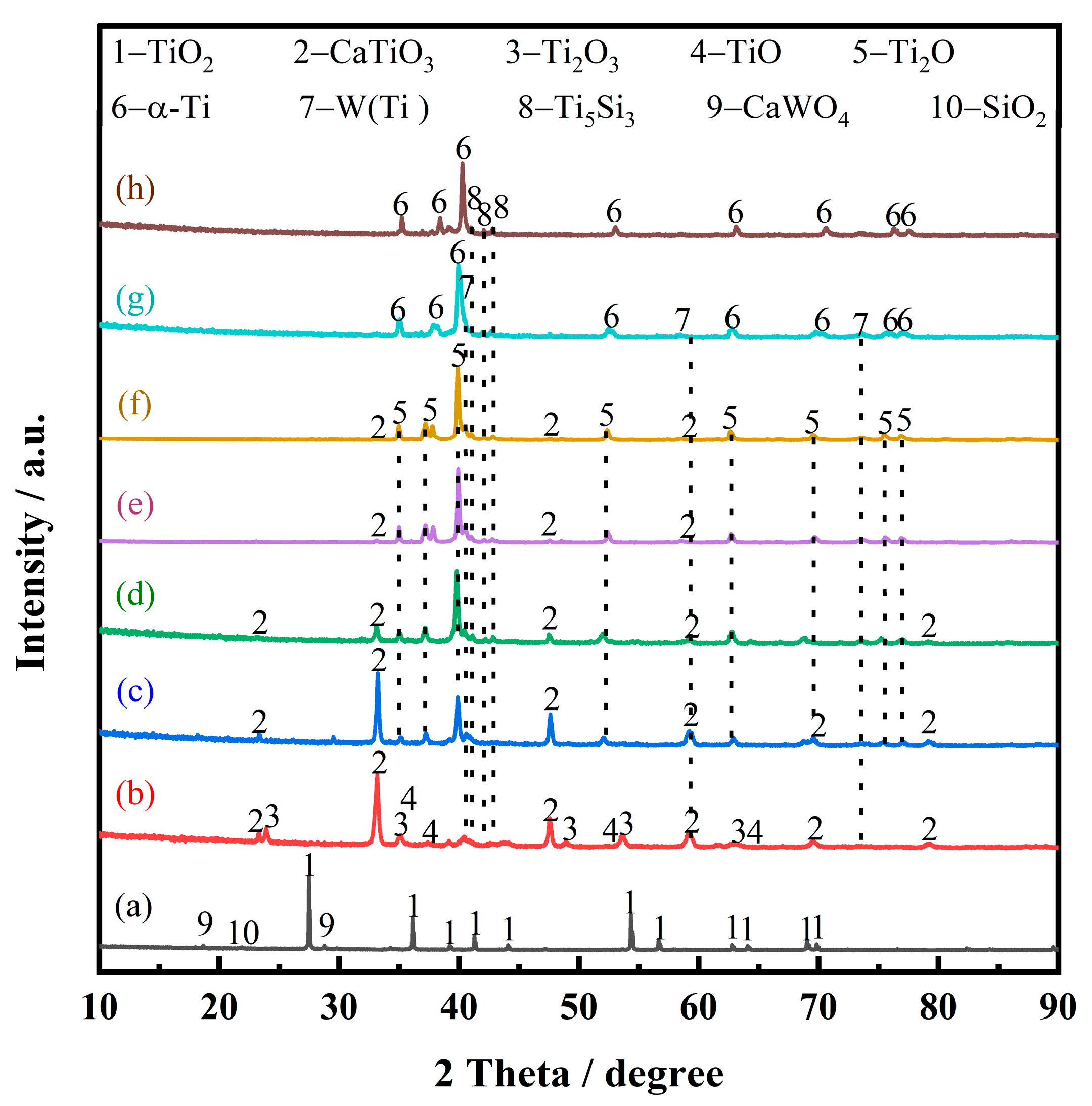
Figure 9 presents the XRD patterns of electrolytic products of spent SCR catalysts with different durations, which can be employed to analyze the electrochemical reduction. After the spent SCR catalysts are immersed in molten salt at 800 °C for 10 min, the main phase remains rutile-type TiO2, as presented in Figure 9a. The secondary phases of CaWO4 and SiO2 show a smaller peak compared with raw materials. This demonstrates that the molten salt has little effect on the spent catalyst without electrolysis.
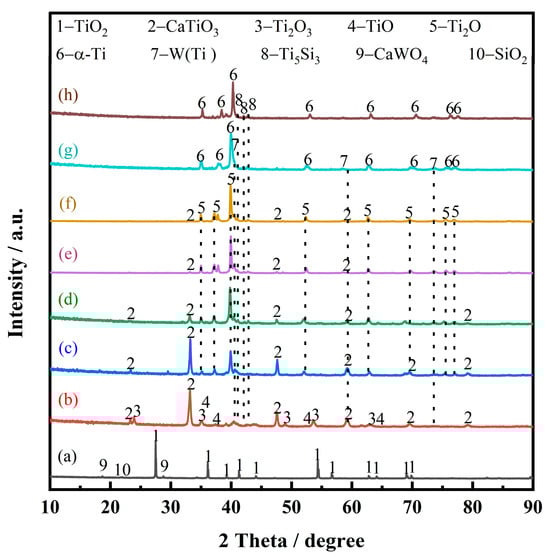
Figure 9.
XRD patterns of electrolytic products of spent SCR catalysts with different durations, immersions into molten salt for 10 min without electrolysis (a), electrolysis within 10 min (b), 0.5 h (c), 1 h (d), 2 h (e), 4 h (f), 8 h (g), and 12 h (h).
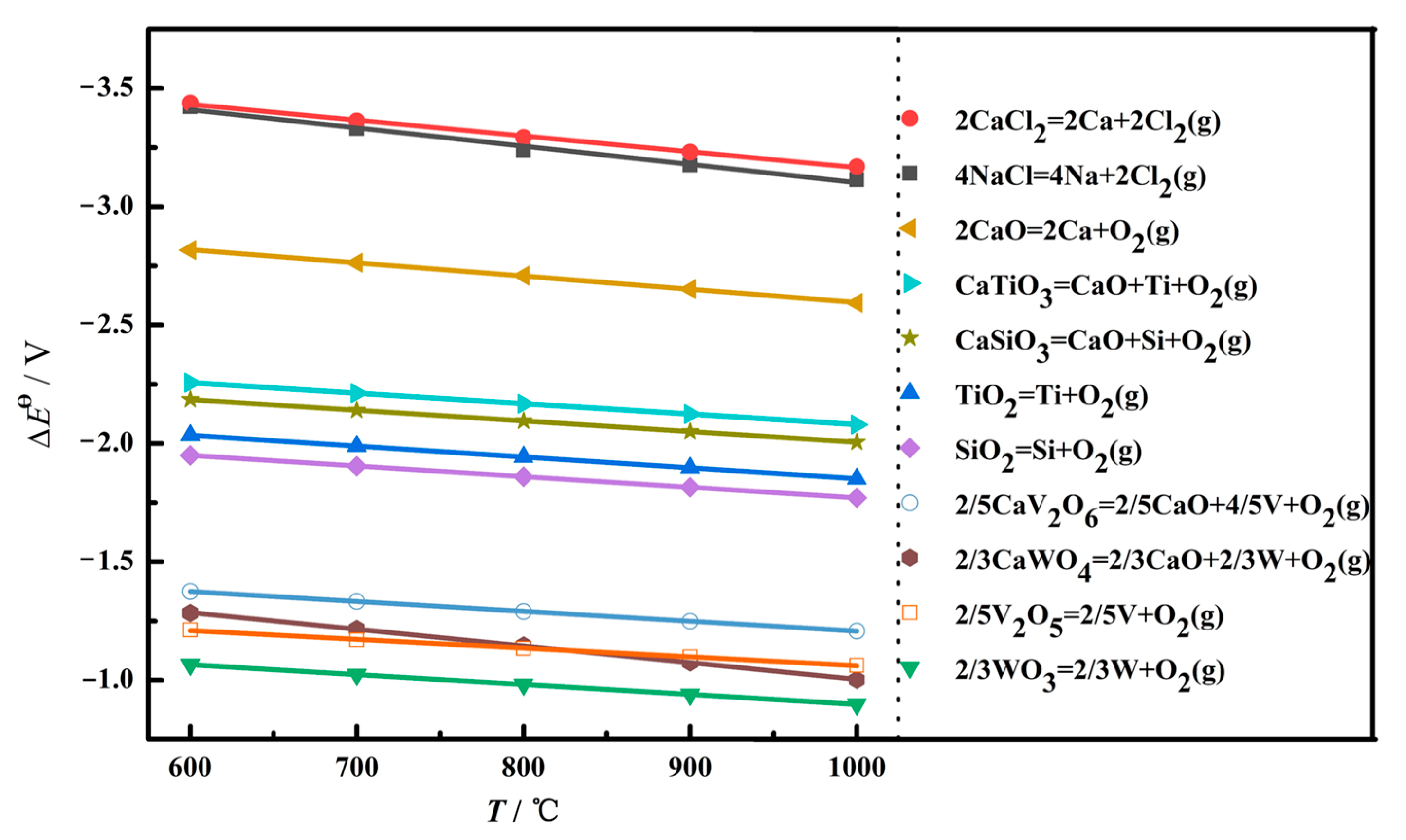
At the initial stage of electrolysis, within 10 min, the main phase composition of the sample is CaTiO3, and some minor phases appear, such as Ti2O3, TiO, W, and Ti5Si3, as shown in Figure 9b. To uncover the reaction mechanism, the theoretical decomposition voltage (∆Eθ) of the possible electrochemical reduction was calculated, as depicted in Figure 10. A larger value of ∆Eθ indicates the corresponding reaction is easier to occur. According to the value of the theoretical decomposition voltage, the order of theoretical electrolytic reduction is WO3, CaWO4, SiO2, CaSiO3, TiO2, CaTiO3, and CaO at 800 °C. it is obvious that CaWO4, CaSiO3, and CaTiO3 require much more negative potentials compared with WO3, SiO2, and TiO2, respectively. This demonstrates the formation of complex oxides generates the barriers for the electroreduction. Combined with the XRD results of Figure 9a, the electroreduction sequence is CaWO4, SiO2, and TiO2. First, CaWO4 was completely reduced to convert into W metal in the electrolytic process, which corresponds to the appearance of W(Ti) in Figure 9b. Then, SiO2 is completely electrochemically reduced to form Si. Moreover, there are three ways for TiO2 at this initial stage. Most TiO2 chemically reacts with O2− and Ca2+ in the molten salt and converts to CaTiO3, which presents a block with a layered stacking structure, as shown in Figure 11a. The oxide ions mainly come from the rapid electroreduction of WO3 and SiO2. Some TiO2 is not completely electrochemically reduced and converted to Ti2O3 and TiO, while some other TiO2 is completely electroreduced to Ti but subsequently reacts with Si to form Ti5Si3 alloy, which is in agreement with the results of Li. et al. [24]. According to the phase composition in Figure 9b, it can be seen that TiO2 is the most difficult to electroreduce, which is consistent well with the theoretical analysis.
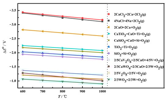
Figure 10.
The relationship between the possible reaction temperature and theoretical decomposition voltage Eθ in the electrolysis process.
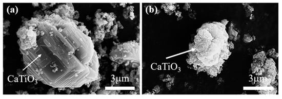
Figure 11.
SEM images of CaTiO3 in the electrolysis process; 10 min (a) and 1 h (b).
Figure 9c shows the phase compositions at the second stage after 0.5 h of electrochemical reduction. With electrolysis, Ti2O comes to emerge, while TiO and Ti2O3 disappear. Also, the relative content of CaTiO3 presents a decrease. So, there are two main transformation behaviors that occur: TiO and Ti2O3 are totally converted to Ti2O with lower valence, and a part of CaTiO3 starts to be electrolyzed and generate Ti2O in one step.
In the electrolytic reduction time range of 0.5 h to 4 h, the main reaction is the electrochemical reduction of CaTiO3. As shown in Figure 9d–f, the XRD peak intensity of CaTiO3 presents an obvious decrease, while Ti2O has an increase. After electrolysis for 4 h, as shown in Figure 9f, there is almost no CaTiO3 detected. This suggests that CaTiO3 is electrochemically reduced to form Ti2O. The micro-morphology image of the electrolytic product is exhibited in Figure 11b. Compared with the sample of the first stage, it is obvious that the particle size of CaTiO3 appears to decrease and has a rough surface. This is also verified by the electrochemical reduction of CaTiO3. The phase transitions are in agreement with the previous study [25]. Ti2O can be obtained from CaTiO3 directly, and there are no observed intermediates of Ti2O3 and TiO. However, the intermediates of CaTiO3, Ti2O3, TiO, and Ti3O5 were detected in the electrolytic process of TiO2. This result is also corresponding to the thermodynamic calculation. CaTiO3 has more negative potentials, which may be lower than the intermediates of TiO and Ti2O3.
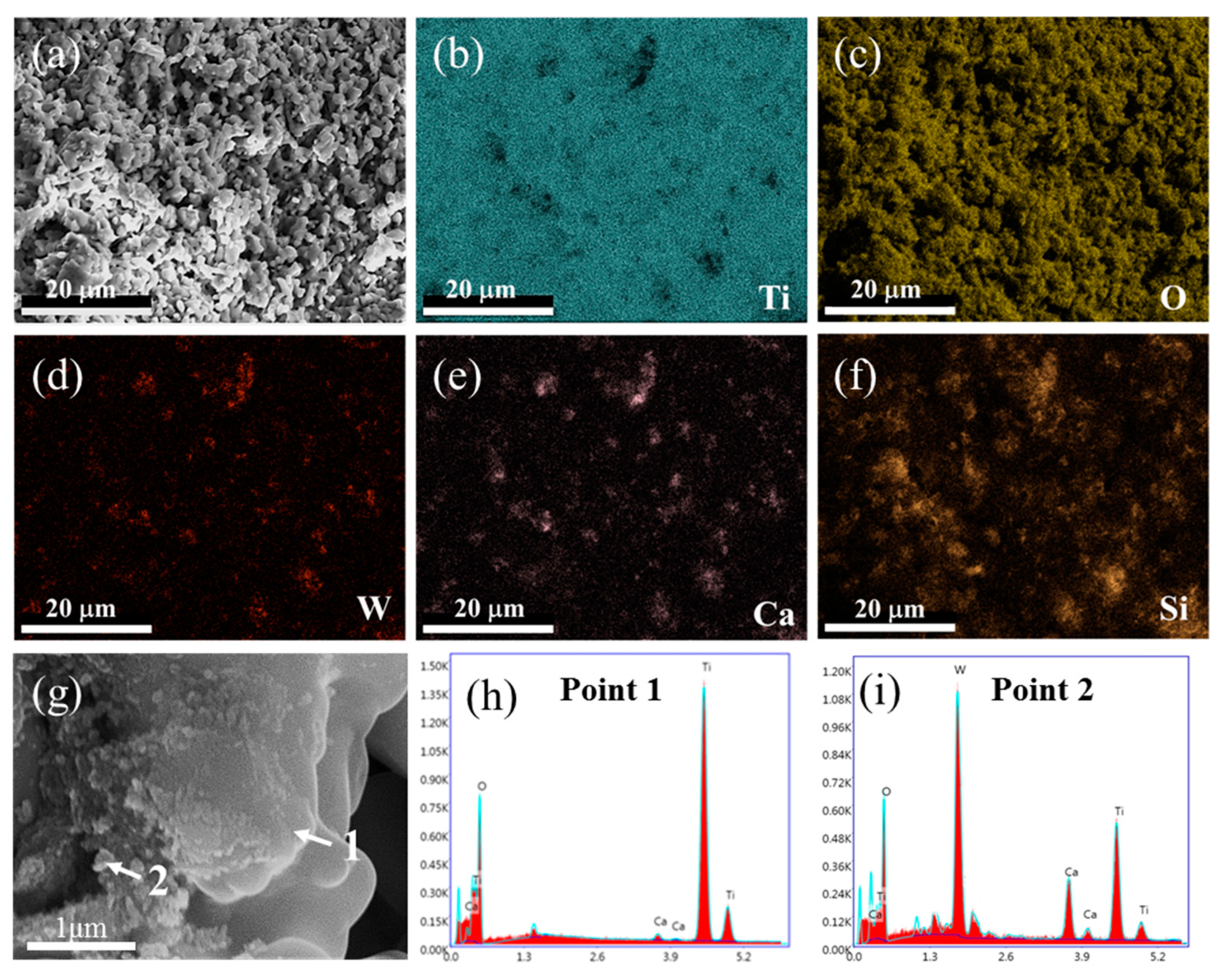
As shown in Figure 9g, the main phase composition becomes α-Ti within 8 h of electrochemical reduction at the V stage. CaTiO3 and low-valence titanium oxides have disappeared. This demonstrates that CaTiO3 and low-valence titanium oxides have been converted to α-Ti by electrolysis. The morphology and elemental distribution of the electrolytic product were also investigated, as shown in Figure 12. From Figure 12a, it can be seen that the electrolytic product presents a sponge-like agglomerated structure, and lots of fine particles are attached to the surface. Figure 12b–f show the elemental distribution. The element of Ti exhibits a homogenous distribution, while a small amount of Ca and O are still observed, suggesting that the electrochemical reduction is not complete, although there are no phase compositions of CaTiO3 and low-valence titanium oxides observed in XRD patterns in Figure 9g. Also, the elemental of W and Si distributes unevenly, which is closely related to the distribution of fine particles. The more tiny particles are located, the more elements of W and Si are distributed. In order to verify this result, a local enlarged zone was investigated, as shown in Figure 12g–f. It is obvious that the large particle with a smooth surface is α-Ti, and the fine particles mainly contain W(Ti) solid solution and Ti5Si3 alloy.
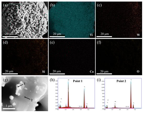
Figure 12.
SEM image (a), elemental mapping analysis (b–f), enlarged SEM image (g), and EDS spot analysis (h–i) of spent SCR catalysts after the electrolysis of 8 h. The locations of 1 and 2 represent the EDS spots.
The final electrolytic product was obtained by 12 h of electrochemical reduction. The main phase compositions are Ti5Si3 and α-Ti, as shown in Figure 9h. There is no W(Ti) phase observed. Meanwhile, it can be seen that the number of fine particles has a significant decrease from the view of Figure 7. This indicates that W(Ti) particles attached to the α-Ti surface have totally diffused into the α-Ti and formed an α-Ti(W) solid solution. This result is consistent with the experimental conclusion of Bhagat et al., which is that a small amount of W(Ti) could be dissolved into α-Ti at this temperature [26]. To summarize, the main changes at the V stage are the electrochemical reduction of Ti2O and the dissolution of W into Ti.
Combined with the time-current curve and phase composition analysis, the electrochemical reduction process is illustrated in Figure 13. At stage I, a part of TiO2, Ca(W, Ti)O4, and SiO2 occur in electrochemical reduction. Among them, Ca(W, Ti)O4 is reduced to form a W(Ti) solid solution, and a part of TiO2 and SiO2 are converted to Ti5Si3. Also, some TiO2 is reduced to lower valence. Meanwhile, the free O2− ions, Ca2+, and TiO2 have chemical reactions together to generate CaTiO3. At stage II, the main transformation is that Ti2O3 and TiO are reduced to form Ti2O. At stages III and IV, CaTiO3 is electrochemically reduced to Ti2O. This reduction process takes a relatively long time. The reason for this is the formation of the CaTiO3 increases the difficulty of deoxygenation. This result is consistent with the conclusion of Hu et al. [27]. At stage V, the Ti2O is further reduced to α-Ti, and W(Ti) is dissolved into α-Ti to form a homogeneous α-Ti(W) solid solution. As an overview of the electrochemical reduction process, the reduction sequence of TiO2 was: TiO2 → Ti2O3 → TiO → Ti2O → Ti, and the reduction sequence of CaTiO3 was: CaTiO3 → Ti2O → Ti. These results agree well with the conclusion of Hu et al. [27].
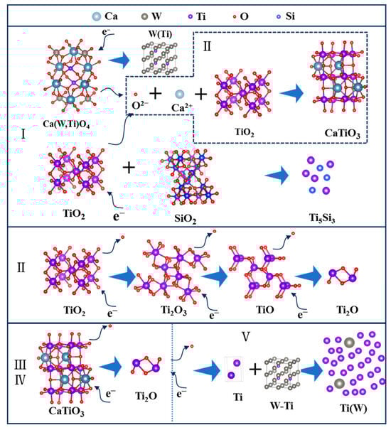
Figure 13.
The electronic reduction process of spent SCR catalysts. I, II, III, IV and V represent different stages of electrochemical reduction.
4. Conclusions
In summary, the titanium alloys of Ti(W) and Ti5Si3 were successfully electrosynthesized from the spent SCR catalyst by using the molten salt electrolysis method at 800 °C and 3.2 V within 12 h in molten CaCl2-NaCl. W presents a uniform distribution, suggesting the solid solution of Ti(W) was formed. The metal recovery rate is in the range of 80–87%. In the electrolytic reduction process, W and Si were first electrolyzed to generate W (Ti) and Ti5Si3 with low theoretical decomposition voltage. CaTiO3 was rapidly formed as an intermediate product in the electrolytic reduction of TiO2. The deoxidation of CaTiO3 and titanium suboxides are the main limiting steps. Titanium alloys containing Ti(W) and Ti5Si3 were formed as final electrolytic products. This result is consistent with the thermal dynamical calculation, in which the electroreduced subsequence is CaWO4, SiO2, TiO2, and CaTiO3. The present study paves the way for the comprehensive utilization of complex solid waste. Using the molten salt electrolytic method to treat the SCR catalyst provides a new direction for the disposal of spent SCR catalyst, in which the electrolytic product of titanium alloys shows a high additional value. In the next work, one objective is to investigate the effects of molten salt compositions or additives on the process efficiency.
Author Contributions
Methodology, L.Z. and J.J.; Formal analysis, L.Z. and Z.C.; Investigation, X.L.; Data curation, J.J. and Q.Z.; Writing—original draft, L.Z.; Writing—review & editing, W.C.; Supervision, Z.C.; Funding acquisition, W.C. All authors have read and agreed to the published version of the manuscript.
Funding
This research was funded by National Natural Science Foundation of China (No. 52104330) and the central government of Hebei Province guides local science and technology development funds (No. 246Z1017G).
Data Availability Statement
Data are contained within the article.
Conflicts of Interest
The authors declare no conflicts of interest.
References
- Li, J.; Chang, H.; Ma, L.; Hao, J.; Yang, R.T. Low-temperature selective catalytic reduction of NOx with NH3 over metal oxide and zeolite catalysts—A review. Catal. Today 2011, 175, 147–156. [Google Scholar] [CrossRef]
- Shi, Q.; Du, X.; Wang, X.; Yang, G.; Wan, Y.; Chen, Y.; Song, L.; Xue, Z.; Zhang, L. Recycling of Waste SCR Catalysts Using a Catalytic Filter: A Study on the Catalytic Performance for NOx Abatement. Ind. Eng. Chem. Res. 2021, 60, 4622–4629. [Google Scholar] [CrossRef]
- Liu, J.; Wang, C.; Wang, X.; Zhao, C.; Li, H.; Zhu, G.; Zhang, J. Reconstruction and recovery of anatase TiO2 from spent selective catalytic reduction catalyst by NaOH hydrothermal method. Chin. J. Chem. Eng. 2023, 60, 53–60. [Google Scholar] [CrossRef]
- Cao, Y.; Han, F.; Wang, M.; Han, L.; Zhang, C.; Wang, J.; Bao, W.; Chang, L. Regeneration of the waste selective catalytic reduction denitrification catalyst by nitric acid washing. ACS Omega 2019, 4, 16629–16637. [Google Scholar] [CrossRef]
- Yang, B.; Zhou, J.; Wang, W.; Liu, C.; Zhou, D.; Yang, L. Extraction and separation of tungsten and vanadium from spent V2O5–WO3/TiO2 SCR catalysts and recovery of TiO2 and sodium titanate nanorods as adsorbent for heavy metal ions. Colloids Surf. A 2020, 601, 124963. [Google Scholar] [CrossRef]
- Feng, E.; Gao, D.; Yu, F.; Chen, J.; Xu, Z.; Zhang, W.; Wang, C.; Gao, Y.; Wen, J.; Huang, G.; et al. TiO2 recovered from spent selective catalytic reduction catalysts as anode material for lithium-ion batteries. J. Clean. Prod. 2024, 444, 141120. [Google Scholar] [CrossRef]
- Zhao, C.; Wang, C.; Wang, X.; Li, H.; Chen, Y.; Wu, W. Recovery of tungsten and titanium from spent SCR catalyst by sulfuric acid leaching process. Waste Manag. 2023, 155, 338–347. [Google Scholar] [CrossRef]
- Liu, J.; Wang, C.; Hou, X.; Li, H.; Wang, X.; Hu, W.; Ge, T.; Zhang, J.; Zhu, G.; Xie, H. Extraction of W, V, and As from spent SCR catalyst by alkali pressure leaching and the pressure leaching mechanism. J. Environ. Manag. 2023, 347, 119107. [Google Scholar] [CrossRef]
- Wang, B.; Yang, Q. Recovery of V2O5 from spent SCR catalyst by H2SO4-ascorbic acid leaching and chemical precipitation. J. Environ. Chem. Eng. 2022, 10, 108719. [Google Scholar] [CrossRef]
- Qian, X.; Ao, W.; Ding, H.; Wang, X.; Sun, S. A Review on Resource Utilization of Spent V-W-Ti Based Selective Catalytic Reduction Catalysts. Materials 2022, 15, 7984. [Google Scholar] [CrossRef]
- Zhao, J.; Zhang, X.; Yang, F.; Ai, Y.; Chen, Y.; Pan, D. Strategy and Technical Progress of Recycling of Spent Vanadium-Titanium-Based Selective Catalytic Reduction Catalysts. ACS Omega 2024, 9, 6036–6058. [Google Scholar] [CrossRef]
- Zhang, X.; Zhang, S.; Deng, L.; Wang, J.; Wu, B.; Liu, B.; Zhang, B. Selective leaching of V, W and recycling of TiO2 carrier from waste V2O5-WO3/TiO2 catalysts by mixed alkali liquor. Sustain. Chem. Pharm. 2023, 36, 101234. [Google Scholar] [CrossRef]
- Ding, L.; Wang, Y.; Qian, L.; Qi, P.; Xie, M.; Long, H. Flue gas deNOxing spent V2O5-WO3/TiO2 catalyst: A review of deactivation mechanisms and current disposal status. Fuel 2023, 338, 127268. [Google Scholar] [CrossRef]
- Choi, I.-H.; Kim, H.-R.; Moon, G.; Jyothi, R.K.; Lee, J.-Y. Spent V2O5-WO3/TiO2 catalyst processing for valuable metals by soda roasting-water leaching. Hydrometallurgy 2018, 175, 292–299. [Google Scholar] [CrossRef]
- Yao, J.; Cao, Y.; Wang, J.; Zhang, C.; Wang, W.; Bao, W.; Chang, L. Successive calcination-oxalate acid leaching treatment of spent SCR catalyst: A highly efficient and selective method for recycling tungsten element. Hydrometallurgy 2021, 201, 105576. [Google Scholar] [CrossRef]
- Xiao, H.; Chen, L.; Qin, Z.; Yin, R.; Weng, D.; Wang, Z.; Luo, D. Separation of vanadium, tungsten and molybdenum from spent SCR catalysts solution by solvent extraction with primary amine N1923. Waste Manag. 2022, 150, 301–309. [Google Scholar] [CrossRef] [PubMed]
- Wang, M.; Zhang, Y.; Li, Z.; Li, J.; Ma, W.; Lei, Y. Preparation of low-oxygen Ti–Al alloy by sustainable recovery of spent SCR catalyst. Sep. Purif. Technol. 2024, 343, 127060. [Google Scholar] [CrossRef]
- Li, Z.; Yang, L.; Ma, W.; Lei, Y. Eutectic Si–Ti brazing alloy prepared from spent selective catalytic reduction catalyst and diamond-wire sawing silicon waste. Chem. Eng. J. 2024, 496, 154053. [Google Scholar] [CrossRef]
- Kang, J.; Tian, Z.; Zhong, D.; Yang, L.; Mao, H.; Qiu, G.; Lv, X. Deoxidation thermodynamics of Ti–O in hydrogen atmosphere: Preparation of TiH2 alloy powder by direct reduction of spent V2O5–WO3/TiO2 catalyst with magnesiothermic. J. Mater. Res. Technol. 2023, 22, 1088–1102. [Google Scholar] [CrossRef]
- Cao, J.; Gu, H.Z.; Wu, J.J.; Wei, K.X.; Zeng, Y.; Ma, W.H. Recycling of Ti and Si from Ti-bearing blast furnace slag and diamond wire saw silicon waste by flux alloying technique. J. Environ. Manag. 2024, 362, 121302. [Google Scholar] [CrossRef] [PubMed]
- Lu, X.; Zhang, Z.; Hiraki, T.; Takeda, O.; Zhu, H.; Matsubae, K.; Nagasaka, T. A solid-state electrolysis process for upcycling aluminium scrap. Nature 2022, 606, 511–515. [Google Scholar] [CrossRef]
- Martin-Treceno, S.; Weaver, N.; Allanore, A.; Bishop, C.M.; Marshall, A.T.; Watson, M.J. Electrochemical behaviour of titanium-bearing slag relevant for molten oxide electrolysis. Electrochim. Acta 2020, 354, 136619. [Google Scholar] [CrossRef]
- Zhou, Z.; Zhang, Y.; Dong, P.; Hua, Y.; Zhang, Q.; Wang, D.; Duan, J.; Zhang, Z. Electrolytic synthesis of TiC/SiC nanocomposites from high titanium slag in molten salt. Ceram. Int. 2018, 44, 3596–3605. [Google Scholar] [CrossRef]
- Li, S.; Zou, X.; Zheng, K.; Lu, X.; Chen, C.; Li, X.; Xu, Q.; Zhou, Z. Electrosynthesis of Ti5Si3, Ti5Si3/TiC, and Ti5Si3/Ti3SiC2 from Ti-Bearing Blast Furnace Slag in Molten CaCl2. Metall. Mater. Trans. B 2018, 49, 790–802. [Google Scholar] [CrossRef]
- Lang, X.C.; Xie, H.W.; Zou, X.Y.; Kim, P.H.; Zhai, Y.C. Investigation on Direct Electrolytic Reduction of the CaTiO3 Compounds in Molten CaCl2-NaCl for the Production of Ti. Adv. Mater. Res. 2011, 284–286, 2082–2085. [Google Scholar] [CrossRef]
- Bhagat, R.; Jackson, M.; Inman, D.; Dashwood, R. Production of Ti–W Alloys from Mixed Oxide Precursors via the FFC Cambridge Process. J. Electrochem. Soc. 2009, 156, E1. [Google Scholar] [CrossRef]
- Hu, M.; Ma, T.; Gao, L.; Lai, P.; Qu, Z.; Wen, L.; Li, D.; Zhang, S.; Hu, M. Phase Transformations and Deoxidation Kinetics during the Electrochemical Reduction of TiO2 in Molten CaCl2. Mater. Trans. 2019, 60, 416–421. [Google Scholar] [CrossRef]


Disclaimer/Publisher’s Note: The statements, opinions and data contained in all publications are solely those of the individual author(s) and contributor(s) and not of MDPI and/or the editor(s). MDPI and/or the editor(s) disclaim responsibility for any injury to people or property resulting from any ideas, methods, instructions or products referred to in the content. |
© 2025 by the authors. Licensee MDPI, Basel, Switzerland. This article is an open access article distributed under the terms and conditions of the Creative Commons Attribution (CC BY) license (https://creativecommons.org/licenses/by/4.0/).