Abstract
The present study presents the results of an analytical and experimental investigation on the behaviour of Al2O3 particles injected into the plasma jet. The dependence of the temperature of the particles and velocity profiles on particle size was estimated by numerically simulating the specific plasma jet in the plasma chemical reactor. The velocity of the particle was investigated experimentally using the ParticleMaster shadowgraphy laser imaging system. The heat flux from the plasma jet to the particles was estimated numerically, and the results were compared with the experimental measurements. Mineral fibre and granules were produced during the plasma spraying process. The studies performed showed that the interaction of the plasma jet and dispersed particles in the reactor mainly depends on the particle’s size, velocity, and temperature of the plasma flow. The modelling and measurements were performed under plasma conditions chosen below the full melting temperature of alumina to avoid particle deposition on the walls while still representative of the reactor environment where finer fractions contribute to melt and fibre formation. The heat flux to the particles inside the reactor increased with the increase in the particle-plasma mass ratio in the reactor.
1. Introduction
The range of applications of atmospheric pressure thermal plasma technology is constantly expanding, as it is a novel technique for the manufacture of newer and more advanced materials, because thermal plasma technology provides high-power density, high temperature, and high-velocity gas flow. Traditional applications of thermal plasma devices (plasma torches) are cutting, welding, particle spheroidization, waste destruction, and other applications in plasma processing and metallurgical engineering [1,2,3,4]. Among these, plasma spraying has been the most widely studied. In this process, fine particles are injected into a plasma jet, rapidly heated and often melted before being deposited on a substrate to form a dense coating [5]. The fundamentals of this process have been extensively described in the literature and are now summarized in several handbooks, such as [6,7].
Despite this large body of work, plasma-assisted fibre formation remains less well understood. Plasma fibrillation differs from conventional spraying in that particles are injected into a confined reactor, where they are melted, accumulated on the cooled reactor walls, and then stretched into fibres by the kinetic energy of the plasma jet. This combined process not only produces stretched ceramic fibres but can also generate nano-dispersed particles and spherical granules [8,9]. The process is carried out using the kinetic energy of high-temperature flow generated by the plasma torch. Performing the plasma fibrillation process, the plasma torch forms a plasma jet, which enters the channel of the plasma-chemical reactor, where it mixes with the injected dispersive particles (50–150 µm). The melted particles stick to the reactor walls as melted mass and flow to the exit of the reactor. The kinetic energy of the plasma jet at the outlet of the reactor drags the small droplets of the melt, stretches them, and forms fibres 10 μm thick and 0.3 m long. Because the process occurs under extreme conditions—temperatures exceeding 3000 K and timescales on the order of milliseconds—direct experimental monitoring of particle behaviour inside the reactor is highly challenging.
The essential factor determining the efficient use of plasma technology for the manufacture of ceramic materials is the determination of optimal parameters of high-temperature jet-particle flows and the geometry of the plasma-chemical reactor. The optimal parameters of the plasma reactor can be selected only after a thorough investigation of the interaction between the plasma jet and the raw dispersed particles of the ceramic materials. The most dominant processes of that interaction are heat and momentum transfer between the plasma jet and dispersed particles. These processes are complicated to monitor and investigate experimentally, as high-temperature and high-velocity particles travel in the ambient of transparent gas, and it is a challenging task to register them and measure their characteristics, even using novel analysis techniques, especially if the particles reside within the reactor channel. So, numerical models are applied to investigate the evolution of temperature and velocity of the particles in the plasma jet.
During the last several decades, significant progress has been made in modelling particle–plasma interactions. Pfender [10] reviewed the fundamentals of heat and momentum transfer to particles in thermal plasmas. The spray trajectories of alumina and tungsten particles in argon plasma, and the heat transfer to them, were calculated. Zhang et al. [11] used numerical models to show the influence of particle size, injection velocity, and plasma parameters on in-flight heating and acceleration in argon-hydrogen plasma jets. Shanmugavelayutham et al. [12] and Ananthapadmanabhan et al. [1] studied alumina–titania and aluminum particles, respectively, while Chaturvedi et al. [13] investigated spheroidization of alumina in a DC argon–nitrogen plasma. The experimental results were supported by a one-dimensional numerical model that simulates the thermal and oxidation behaviour of the particles. The results showed that increasing the power of the plasma torch enhances particle melting and spheroidization but may not result in complete phase transformation because of the limited residence time and the low thermal conductivity of alumina. Xiong et al. [14] and Bai et al. [15] employed thermal resistance analysis to control the melting states of particles during spraying.
More recently, Grimm et al. [16] showed that the degree of alumina melting strongly affects phase transformations during spraying, and Allofs et al. [17] demonstrated advanced particle diagnostics using the LaVision ParticleMaster system. Other studies have linked in-flight particle conditions to coating properties [18,19] or deposition efficiency [20]. Additional numerical work has extended the analysis to particle heat exchange in different plasma environments [21,22,23,24,25,26].
However, most of these studies focus on open-jet configurations and inert gas plasmas, and much less attention has been given to air plasma reactors, where the plasma is confined, and the interaction of the jet with the reactor walls and injected particles plays a critical role. For ceramic fibre production, this knowledge gap is particularly important, as the efficiency of melting and fibrillation depends strongly on the size of the particle, the residence time, and the heat transfer under these enclosed conditions.
The thermal and kinetic behaviour of particles in atmospheric plasma jets has been extensively investigated, with comprehensive treatments available in [7,27]. However, most studies focus on inert-gas plasmas (Ar, Ar–H2) and open-jet atmospheric plasma spraying (APS) configurations, where particle acceleration, melting, and coating formation have been systematically modelled and validated. Recent advances by Wei et al. include high-fidelity simulations that incorporate variable transport properties and plasma–particle coupling [28], as well as Jeon et al. studies of gas composition effects on jet characteristics and particle heating [29]. Other researchers have examined the role of feedstock morphology and injection strategies on in-flight particle behaviour and coating properties in APS [30]. Recent work has advanced in-flight diagnostics and modelling for APS conditions. The results obtained by other authors report measurements of particle temperature/velocity and uncertainty reduction strategies for in-flight characteristics using data-driven methods, which reinforces the importance of quantitative near reactor’s exit diagnostics [31,32,33]. Likewise, new APS modelling in air or shrouded configurations with variable properties (including multi-cathode sources and nozzle-extension effects) documents how confinement and composition alter jet decay and energy delivery [34]. Energy-accounting perspectives that connect torch output to substrate and coating heat input have also been refined in order to interpret the wall heat flux in partially confined sprays [35].
In contrast, data for confined air plasma reactors remain scarce, despite their importance for ceramic fibre production and plasma-chemical synthesis processes. The interaction of particles with the plasma jet under flow through an enclosed channel, the resulting wall heat fluxes, and the onset of melt layer formation are not as well documented as in open spraying systems.
The present work addresses this gap by combining a simple one-dimensional Lagrangian model with experimental calorimetric energy balances and in-flight velocity measurements to study alumina particle heating and acceleration in a confined air plasma jet. This integrated approach enables the evaluation of heat flux transfer as a function of the particle–plasma mass ratio and provides experimental data relevant for optimizing fibre production regimes under sub-melting conditions.
Therefore, this work aims to investigate the in-flight behaviour of alumina particles (Al2O3) in an air plasma jet confined within a plasma-chemical reactor designed for fibre production. In practical operation, a fraction of the alumina particles melt and contribute to fibre formation on the reactor walls. However, in this study we selected operating regimes in which the tracked particles (50–150 µm) remain below the melting point to allow for controlled investigation of their in-flight heating and acceleration. A one-dimensional Lagrangian model is applied to estimate particle velocity, temperature, and heat flux, and the results are validated against in-flight velocity measurements using the ParticleMaster measuring system. By directly comparing model predictions with calorimetric experiments, this study provides new insight into how particle size, plasma jet velocity, and particle-to-gas mass ratio influence heating and acceleration. The results contribute to a better understanding of plasma-assisted fibre production and support the optimization of operating parameters for efficient ceramic processing. This study addresses this gap by investigating the behaviour of alumina particles in an enclosed air plasma jet, integrating modelling and experiments, and focusing on the optimization of the process for the production of ceramic fibres.
2. Experimental Set-Up and Methodology
The processing of hard ceramics, such as Al2O3, SiO2, various zeolites or their compounds, and the production of high-temperature resistant fibre is related to high-temperature features (above 2300 K), which causes difficulties in the use of traditional technologies. Low-temperature plasma jet generation equipment and a plasma chemical reactor were used in this experimental research to process hard ceramics. Experiments for ceramic fibre production were performed using a linear single-chamber plasma torch. Such plasma torches are characterized by very stable operating parameters. The main operating parameters of the plasma torch used for fibrillation experiments are: power supply (P)—70–120 kW, arc current (I)—150–300 A, arc voltage (U)—250–400 V, total air flow rate (G)—15–30 g/s, average outlet temperature (T)—2800–3800 K, average outlet velocity (v)—650–1250 m/s. The average temperature and velocity of the outlet jet were determined from the heat balance. The capacity of the plasma torch, the mass flow of gases, the cooling water, and its temperature were measured, and the gas enthalpy was calculated. These data were used to calculate the mean plasma temperature and velocity numerically, employing thermophysical properties for “frozen-composition” air from J. M. Yos [36]. A detailed description of the plasma torch design and its operational characteristics can be found in [37,38].
A stream plasma-chemical reactor (the extension channel) was designed and produced for hard ceramics processing. The reactor appears as a 0.24 m long (x) and 0.016 m wide (y) cylinder made of stainless steel (maximum ratio x/y = 15) (Figure 1).
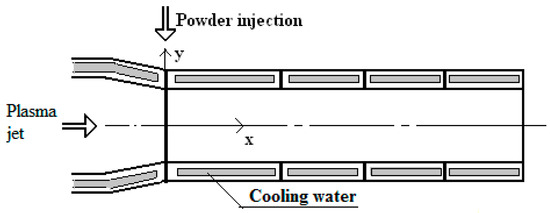
Figure 1.
The scheme of the plasma chemical reactor.
The plasma-chemical reactor consisted of four water-cooled sections: the first section was 0.09 m in length, while the remaining three sections were each 0.05 m long. All sections were cooled by water. Sectional calorimetry was performed by measuring the cooling water flow rate and the temperature rise in each section. These data were used to establish the plasma jet mean temperature and velocity distributions along the reactor channel and to evaluate the heat transfer from the plasma jet to the reactor walls.
Commercial Al2O3 powders 50–150 µm in size were used for particle processing experiments. After being sieved and dried, the powders were used to form the two-phase plasma jet. The heat flux between the plasma and the dispersive particles in the reactor channel was measured by comparing the heat transfer to the reactor walls with and without the dispersive particles. Experimentally, the velocity of particles leaving the reactor was established employing the ParticleMaster shadowgraphy imaging system using pulsed backlight illumination. The image pairs were recorded at 10–15 Hz with a delay Δt = 1−2 μs for velocity calculation and exposure ≈ 20 ns to freeze fast motion and suppress plasma glow. The field of view in the measurement plane was 10 × 10 mm2, the appropriate depth of field was ≈5–10 mm, determined by the LaVision’s calibration set and used for absolute density/flux corrections. The imaging camera was positioned right at the reactor exit, centred on the jet axis. The optical axis was perpendicular to the jet to minimize perspective and glare. The system reliably measured particle sizes ≥ 5 µm and particle velocities of up to 500–600 m/s under our conditions.
3. Theoretical Modelling of the Particle-Plasma Interaction
The numerical models of interaction between the plasma jet and in-flight particles found in the scientific literature were generalized and applied for this study. Theoretical modelling of a particle treatment in a plasma jet consists of the evaluation of its physical characteristics along its flight trajectory. For the numerical modelling of the dispersed phase, the Eulerian or Lagrangian approach can be used [39]. However, the Lagrangian approach is closer to the physical reality and yields the information necessary to accurately predict particle motion in the turbulent field. For this reason, it has been chosen for the present work.
For the present research, two characteristics of a single particle in a plasma jet were studied: motion (velocity and acceleration) and thermal evolution (temperature and heat flux). The particles were assumed to be rigid and spherical. Problems related to the powder morphology are not considered. It was considered that there were no chemical reactions between the particles and the turbulent plasma jet.
Two kinds of forces act on the particle in the plasma reactor—those acting permanently and those acting as impulses. The permanent forces influencing particle movement are essentially drift force (FD) and gravity (FG) [10]. This hypothesis simplifies the equation of the trajectory of the particles, neglecting some active forces. The pulsed forces are caused by particle-wall and particle-particle interactions, which in this work will not be taken into account because only one particle will be considered, and the influence of the reactor wall will be credited only for characteristics of the plasma jet. Also, modelling particle-wall collisions is complicated as the particles change shape and size after impact or even stick to the wall.
When a particle and a fluid (here, plasma) are in relative motion, a drift force is given by the fluid to the particle. This force comes from the dissymmetry of the moving line between the particle upstream and downstream. The drift force is the most influential on the trajectory and acceleration of the particles. This force (FD) is calculated by Equation (1) [12]:
where CD—the drift coefficient that depends on the morphology of the particle and the Reynolds number (no dimension); dp—the diameter of the particle (m); ug − up—the difference between the plasma velocity and the velocity of the particle (m/s); ρg—the plasma density (kg/m3), ρp—the density of the particle (kg/m3).
CD can be expressed as [11]:
The function f(Rep) is given by:
where the Reynolds number of the particle Rep is defined as [23]:
where μg—the plasma viscosity.
A particle injected into the plasma flow is heated, melted, and evaporated. The instantaneous increase in particle temperature is given by [12]
where k—the thermal conductivity of the plasma, Cp—the specific heat of the particle, Tg − Tp—the difference between the plasma temperature and the particle temperature (K);
The specific heat values of the particles at the corresponding plasma jet parameters were calculated using a multilinear fitting equation [40].
The heat transfer coefficient is obtained from the Nusselt number (Nu), which is described for spherical-shaped particles as
where h—heat transfer coefficient, k—thermal conductivity of plasma, Pr—Prandtl number.
A semi-analytical approach was adopted to solve the equations of particle motion and temperature rise. To realize this approach, we divided the entire time interval during which the particle was followed into subintervals. The particle position, velocity, and temperature, as well as the plasma jet temperature and velocity, were calculated at the end of each subinterval. The acting forces were considered constant during one subinterval.
During plasma spraying, the particles are usually moving in the open environment where the plasma jet temperature is assumed to follow an exponential decay, and the velocity profile varies in a parabolic manner. The experimental measurements showed that the mass averaged gas velocity (ug) and temperature (Tg) decreased approximately linearly along the length of the reactor channel along the axial direction (x). These profiles can be expressed as:
where ug0 and Tg0 are the mass-averaged velocity and temperature of the plasma at the reactor inlet, x is the axial distance from the inlet (m), D is the channel diameter (m), and ku, kT are dimensionless slope coefficients obtained from linear regression of calorimetric data (on the order of 0.01). The uncertainty of the reconstructed profiles ug(x) and Tg(x) is estimated at ±5% based on repeated calorimetric measurements and ug, Tg are cross-sectional mass averages.
The average temperature (Tg) of entering the reactor plasma jet was determined to depend on the geometry of the plasma torch, the arc current, and the air flow of the plasma forming. It can be estimated from the equation
where I is the arc current of the plasma torch, G is the plasma forming air flow rate (g/s), dt is the diameter of the plasma torch chamber (m).
The standard gas dynamic equation is used in the vast majority of papers that seek to calculate the heat flux to the particle in a weakly ionized plasma [23]:
where Tg is the average temperature of the plasma jet (K), Tp is the average temperature of the particle (K), dt is the diameter of the chamber of the plasma torch (m), dp is the diameter of the particle (m), and Nu is the Nusselt number.
4. Results and Discussion
During the melting and fibrillation process of ceramic materials in the plasma environment, as the plasma chemical reactor walls are cooled (the experiments showed that their temperature does not exceed 550 K for plasma temperatures up to 5000 K) and because of the injection manner of purposefully processed materials (the dispersed materials are inclined to stick to the reactor walls in order to increase the duration of their interaction with plasma jet), a thin solid layer of melt is formed directly on the wall surface with viscous liquid layer on them. Due to a high plasma jet kinetic energy and velocity, the plasma jet slowly moves the viscous melt layer on the reactor walls toward the exhaust nozzle. The plasma jet carries the material away in liquid volume form, forming elongated fibre filaments. The SEM image in Figure 2 shows typical ceramic fibres produced by this plasma fibrillation process. The elongated and continuous filament structure is obtained from molten material transported along the plasma-chemical reactor wall.
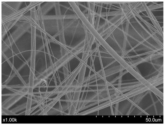
Figure 2.
Ceramic fibre prepared by plasma fibrillation technology.
The morphology of the melt layer in the plasma-chemical reactor is illustrated in Figure 3, which presents both the schematic formation process and a photograph of the solidified layer. This double-layer structure confirms that plasma–particle and wall interactions play a significant role in the melting, transport, and formation of fibres of the material.
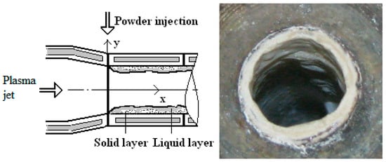
Figure 3.
Schematic of melt formation on the walls of the reactor (left) and solid melt layer (right).
After mixing with the plasma jet, the solid particles have a lower temperature than the jet, and a certain time is needed to heat them up. The particles have to be relatively fine to heat up quickly. Heating of particles in the plasma jet occurs while releasing heat by convection, whereas the heat inside the particles is transferred by conduction.
Reliable and stable operation of the plasma generator (PG) is crucial for reproducible fibre production. The most critical parameters of the plasma jet during ceramic fiberization are temperature and velocity. Our previous studies showed that complete melting and fibre formation require a plasma jet temperature of 2500–3000 K and a velocity of 700–1000 m/s at the reactor inlet, which can be achieved at a torch power of 60–80 kW and plasma-forming air flow of about 20 × 10−3 kg/s. The plasma jet temperature at the reactor outlet must be 500–600 K above the melting point of the ceramic particles (1500–2000 K) to ensure a sufficiently low melt viscosity for fibre formation.
More than 150 experiments were conducted under varying current (130–250 A) and air flow conditions to determine the volt–ampere characteristics (V–A curves) of the torch. The resulting curves (Figure 4) are positively sloped, indicating that arc voltage increases with current. Such a characteristic, typical for torches with a stepped anode, ensures stable arc burning, reduces arc restrikes, enables easier power control, and allows achieving higher gas temperatures without using ballast resistance in the power circuit.
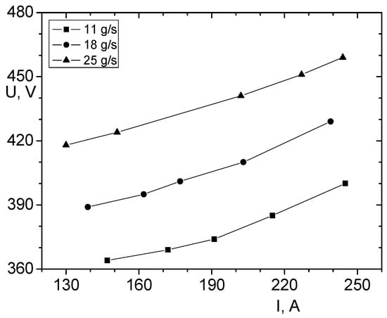
Figure 4.
Volt–ampere characteristics of the plasma torch for three plasma-forming air flow rates (11, 18, and 25 g/s). The positive slope indicates stable arc operation and efficient power transfer to the plasma jet.
As mentioned above, the dispersed particles melt during the fibrillation process, forming a melt layer on the reactor walls. Thus, the temperature and velocity variation in the particles in the reactor channel, which provides valuable information about the optimality of the fibrillation process, is impossible to monitor. Because in situ measurement of particle temperature and velocity inside the reactor channel is challenging, numerical modelling and selective in-flight measurements were used to investigate these parameters. Three operational regimes (Table 1) were tested, with particle sizes of 50, 100 and 150 µm injected at 1 g/s. The resulting particle–to–gas mass ratio was 0.10–0.30, corresponding to a proper particle volume fraction in the reactor core of approximately 10−4–10−3. At these low loadings, the gas flow field can be assumed to be unaffected by the particles, which justifies the use of a one-dimensional, one-way-coupled Lagrangian model. Therefore, the temperature and velocity variations in one particle that interacts with the plasma jet were studied. However, during the experiments, the operating regimes of the plasma chemical reactor were selected to ensure that the particles would not exceed the melting point (~2350 K) and would not stick to the reactor walls. The following calculations and measurements were carried out under sub-melting regimes to avoid particle sticking and to enable reliable velocity and heat flux determination. Under real fibre production conditions, fine particles typically reach melting temperatures and form the observed wall melt layers. The average plasma gas temperature Tg0 and the velocity ug0 reported in Table 1 were reconstructed from a steady-state global energy balance using the measured electrical input power, total wall heat losses from calorimetric measurements, and the known mass flow rate of plasma-forming air. The mean velocity was then obtained from the gas-dynamic continuity relation using the average density corresponding to Tg0. These quantities were calculated according to Equations (7)–(9) and represent cross-sectional mass averages at the reactor exhaust plane. The core plasma temperature and velocity are significantly higher than these average values and are the primary drivers of particle heating.

Table 1.
Operating parameters of the plasma torch.
The analytical calculations of the particle temperature and velocity were performed according to these experimental regimes of the plasma-chemical reactor. The particles were assumed to be injected into the plasma jet flow at the same axial injection velocity of 5 m/s and at room temperature. The variation in particle axial velocity and temperature as a function of its axial distance from the injection place located at the beginning of the reactor channel and the residence time of the particle in the reactor are calculated, and the results are presented in Figure 5 and Figure 6.
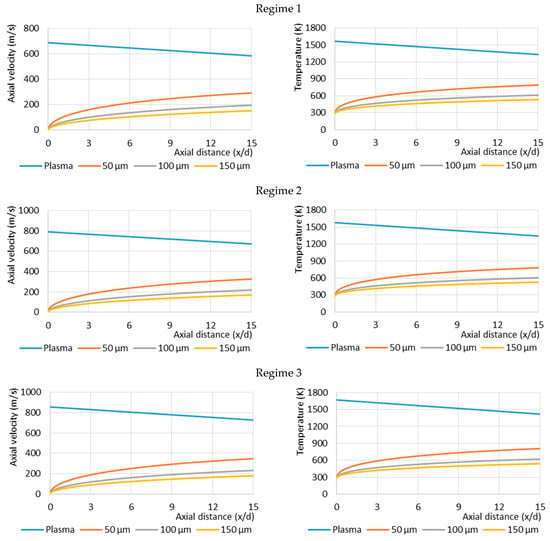
Figure 5.
Dependence of the calculated velocities (left) and temperatures (right) of Al2O3 particles on the axial distance from the injection point under three plasma reactor regimes (top—Regime 1, centre—Regime 2, bottom—Regime 3, see Table 1).
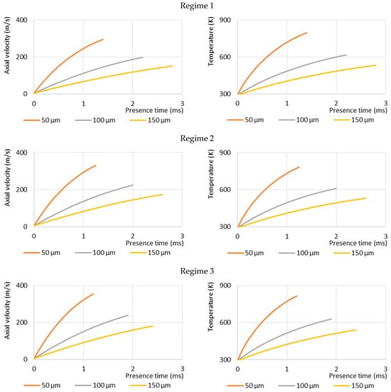
Figure 6.
Dependence of the calculated axial velocities (left) and temperatures (right) of the single Al2O3 particles on the presence time of the particle in the reactor channel under three plasma reactor regimes (top—Regime 1, centre—Regime 2, bottom—Regime 3, see Table 1).
Figure 5 shows the influence of particle size on their axial velocities and temperatures at three different plasma reactor regimes (Regime 1, Regime 2, Regime 3 according to Table 1). This indicates that particle size is a very important factor in determining the particle velocity and temperature variation, even when the particles are injected under the same plasma jet conditions. The velocities of the smaller particles (50 μm) are up to two times higher than the larger ones (150 μm) at the reactor exit nozzle. The acceleration of all-sized particles is high at the beginning of the reactor but significantly decreases subsequently. Also, it can be noted that at different plasma reactor regimes, higher velocities are achieved by particles injected into the higher velocity plasma jet. It is influenced by an increased drag force applied to the particles. Plasma jet velocity increases by 25% (from 690 m/s to 860 m/s), and it affects the particle velocity increase by around 20% (from 290 m/s to 350 m/s for smaller particles and from 150 m/s to 180 m/s for bigger ones). Particle Reynolds number Rep ranges by regime and particle size
The same effects of the evolution of the particle temperature in the plasma reactor can be observed. The smaller particles reach higher temperatures, and as the diameter of particles decreases, the temperature increase is more rapid. The increase in plasma jet temperature from 1570 K to 1670 K leads to an increase in the maximum temperature of 50 µm particle in the reactor from 800 K to 820 K, and from 530 K to 540 K for 150 µm particle.
The particle presence time in the plasma reactor channel also depends on the particle size (Figure 6). The calculations show that it takes only 1.5 ms for the smallest particle (50 μm) to fly through the length of the reactor. Meanwhile, the largest particle (150 μm) takes up to 3 ms for the same distance. It is also seen that as the plasma velocity is higher, the particle residence time in the reactor is shorter: the increase in plasma flow velocity from 690 m/s to 860 m/s decreases the smallest particle (50 µm) residence time in the reactor from 1.4 to 1.2 ms, and the residence time of the 150 µm particle decreases from 2.8 to 2.4 ms. These calculations show how rapidly the particle temperature increases as it is injected into the plasma flow. It takes up to 2.5 ms to increase the temperature of the particles from room temperature to 500 K. The residence time of the particle in the reactor is a necessary parameter to estimate the melting index of the particles if they reach the melting point [18].
These results of particle velocity calculations were compared with experimental ones obtained by means of the ParticleMaster shadowgraphy imaging system by LaVision. The laser and high-speed camera in the shadowgraphy system were mounted in front of each other and perpendicular to the plasma jet. The laser illuminated the dispersed particles, and the high-speed camera captured their movements. From the data obtained, the velocity of the particle was calculated and presented in Figure 7 compared with the analytical measurement curves, which show the calculated velocity of particles of different sizes at the outlet of the reactor channel.
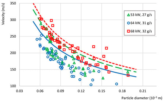
Figure 7.
The experimental (symbols) and analytical (lines) results of particle velocity estimations for three plasma reactor regimes (Regime 1—green, Regime 2—blue, Regime 3—red, see Table 1).
Figure 7 shows that the calculated values of the particle velocity are higher than the velocities estimated experimentally in large part at all regimes. This can be explained by the interaction of particles between each other and with the reactor walls, which are not taken into account in the calculation [27]. In addition, the particle’s velocity at the reactor outlet varies due to the different conditions experienced by the particles in the reactor. The discrepancies are attributed to particle–particle and particle–wall interactions and non-uniform velocity distributions within the plasma jet (core vs. periphery). So, the velocity of particles penetrating and travelling inside the dense plasma jet is higher. It was noticed that the calculated and measured results correlate better as the plasma jet velocity is higher (Regime 3). The few experimental points above the calculated curves are attributed to local jet velocity variations and to the ±5–10% uncertainty of the shadowgraphy measurements. Moreover, the alumina feedstock was sieved to remove particles < 50 µm and confirm the absence of finer ones.
As mentioned above, the use of plasma technologies in practice depends on a number of factors: the characteristics of the plasma generator and plasma-chemical reactor, the interaction of plasma flow and particles of raw material, the geometry of the plasma-chemical reactor, the chemical composition of materials, etc. However, heat transfer between the plasma jet and the particles injected into the chemical reactor channel is the most crucial process. The amount of plasma jet energy used for melt conversion into the fibre is under investigation and discussion. So, the control of heat flux from the plasma flow to the dispersive material and heat losses to the reactor walls becomes the most important issue in optimizing the fibrillation process.
The amount of energy transferred from the plasma jet to the particles for their heating was determined experimentally and analytically. Experimentally, it was assumed that the heat flux to the particles is equal to the difference between the measured heat flux from the plasma jet to the reactor walls with dispersive particles in the reactor and the heat flux without particles. At constant plasma reactor parameters, the mass ratio of dispersive particles and plasma-forming air flow was changed, and the heat flux to the particles was evaluated. The results are presented in Figure 8.
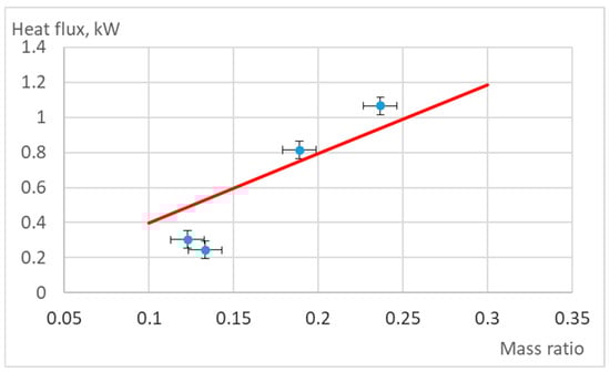
Figure 8.
Experimentally (dots) measured and analytically (curve) calculated dependence of heat flux transferred to the dispersed particles and plasma forming air flow mass ratio.
The plasma torch parameters used for the experiments and the calculations are presented in Table 1 as Regime 2. Al2O3 particles of 50 µm size were used. The calculations considered the temperature variation in the reactor of one particle, as presented in Figure 5 for Regime 2 of the 50 µm particle.
Figure 8 shows the averaged heat flux q′′ [kW·m−2], defined as the net power absorbed by all particles divided by the surface area of the internal wall of the reactor channel.
The calculations showed that the alumina particle mass ratio increase in the air plasma jet from 0.1 to 0.3 increases the heat flux to the particles from 0.4 kW/m2 to 1.2 kW/m2. The results showed that the experimental and calculation data agree well with particle and air mass ratios of up to 0.3. Due to technical restrictions of the particle feeder used, higher ratios could not be achieved. The dynamic gas equation and estimation of particle temperature employing the presented methodology and plasma reactor parameters used in this work correctly describe the heat flux to the particles and can be used to foresee, control, and optimize the fibrillation process. The results confirm that particle size is the most important control parameter in plasma-assisted fibre production. Smaller alumina particles heat and accelerate faster, improving the probability of complete melting before wall contact, but excessively small sizes may reduce residence time and limit heat absorption. Larger alumina particles require longer residence time and higher plasma velocities to approach melting, but risk incomplete melting and defects in the final fibres. The good agreement between the predicted and measured heat flux confirms the use of the presented model for process optimization, enabling better control of melting conditions, energy efficiency, and final fibre quality.
The works mentioned above consider open APS (often based on argon gas) and report higher centerline temperatures, the present study addresses an air plasma jet confined within a reactor channel, couples reactor calorimetry with in-flight particle velocity diagnostics and analyzes sub-melting alumina particles (50–150 µm). Our operating ranges (the mass-averaged outlet temperature Tg∼1600–1700 K and slip Reynolds numbers Rep∼400) are lower than typical open plasma jet centerlines but are directly relevant to closed-channel fibre formation, where wall heat-flux partitioning and residence-time-limited heating govern melt-layer development. This research complements the APS literature by supplying confined-reactor data for interpreting particle-jet interaction in enclosed air plasmas.
5. Conclusions
This study combined numerical modelling with experimental diagnostics to investigate the in-flight behaviour of alumina particles (Al2O3) (50–150 µm) injected into a confined air plasma jet in a plasma-chemical reactor’s channel used for ceramic fibre production. A one-dimensional Lagrangian model was employed to determine the particle temperature, velocity, and residence time. The experimental measurements were performed employing a ParticleMaster shadowgraphy system for particle velocity validation.
The results demonstrated that particle size is the dominant parameter determining heating and acceleration: smaller particles attained up to twice the exit velocity of the largest particles and reached higher temperatures within significantly shorter residence times. Increasing the plasma jet velocity from 690 m·s−1 to 860 m·s−1 increased the particle velocity by approximately 20% and reduced residence time by up to 14%, whereas a 100 K increase in plasma gas temperature produced only a modest rise in particle temperature (~20 K).
The heat flux transferred from plasma to particles increased nearly threefold (from 0.4 to 1.2 kW·m−2) as the particle-to-air mass ratio increased from 0.1 to 0.3, and the calculated values were well in agreement with experimental calorimetry for mass ratios ≤ 0.3. This agreement confirms that the applied modelling approach and heat flux estimation method can reliably describe energy transfer under sub-melting conditions.
The findings emphasize that precise control of the particle size distribution and plasma jet velocity is essential to achieve stable wall melt layer formation and reproducible ceramic fibre drawing. The validated methodology presented here provides a quantitative framework for optimizing reactor operating regimes and improving the energy efficiency of plasma-assisted ceramic processing. The results will be helpful in optimizing reactor conditions, improving energy efficiency, and enhancing the quality of plasma-processed ceramic products.
Author Contributions
Conceptualization, M.M., R.K., V.G. and V.V.; Data curation, M.M., R.K., V.G. and V.V.; Formal analysis, M.M. and V.G.; Investigation, M.M., R.K., V.G. and V.V.; Methodology, M.M., V.G., V.V. and R.K.; Supervision, R.K. and V.V.; Writing—original draft, V.G. and M.M.; Writing—review and editing, V.G., V.V. and M.M.; visualization, M.M. and V.G. All authors have read and agreed to the published version of the manuscript.
Funding
This research received no external funding.
Data Availability Statement
The authors confirm that the data supporting the findings of this study are available within the article.
Conflicts of Interest
The authors declare that they have no conflict of interest.
References
- Ananthapadmanabhan, P.V.; Thiyagarajan, T.K.; Sreekumar, K.P.; Venkatramani, N. Formation of nano-sized alumina by in-flight oxidation of aluminium powder in a thermal plasma reactor. Scr. Mater. 2004, 50, 143–147. [Google Scholar] [CrossRef]
- Venkatramani, N. Industrial plasma torches and applications. Curr. Sci. 2002, 83, 254–262. [Google Scholar]
- Tendero, C.; Tixier, C.; Tristant, P.; Desmaison, J.; Leprince, P. Atmospheric pressure plasmas: A review. Spectrochim. Acta Part B 2006, 61, 2–30. [Google Scholar] [CrossRef]
- He, J.; Bai, L.; Jin, H.; Yuan, F. Optimization of tungsten particles spheroidization with different size in a thermal plasma reactor based on numerical simulation. Powder Technol. 2016, 302, 288–297. [Google Scholar] [CrossRef]
- Fan, J.; Zhang, X.; Chen, L.; Cen, K. New stochastic particle dispersion modeling of a turbulent particle-laden round jet. Chem. Eng. J. 1997, 66, 207–215. [Google Scholar] [CrossRef]
- Fauchais, P.L.; Heberlein, J.V.R.; Boulos, M.I. Thermal Spray Fundamentals; Springer: Boston, MA, USA, 2014. [Google Scholar] [CrossRef]
- Boulos, M.I.; Fauchais, P.L.; Pfender, E. Handbook of Thermal Plasmas; Springer International Publishing: Cham, Switzerland, 2016. [Google Scholar] [CrossRef]
- Valinčius, V.; Snapkauskienė, V.; Kėželis, R.; Valinčiūtė, V.; Mečius, V. Preparation of insulating refractory materials by plasma spray technology. High Temp. Mater. Proc. 2006, 10, 365–378. [Google Scholar] [CrossRef]
- Valinčiūtė, V.; Kėželis, R.; Valinčius, V.; Valatkevičius, P.; Mėčius, V. Heat transfer in a plasma jet reactor for melting and melt fibrillation of hard ceramics. Heat Transf. Res. 2008, 39, 609–618. [Google Scholar] [CrossRef]
- Pfender, E. Heat and momentum transfer to particles in thermal plasma flows. Pure Appl. Chem. 1985, 57, 1179–1195. [Google Scholar] [CrossRef]
- Zhang, T.; Gawne, D.T.; Liu, B. Computer modelling of the influence of process parameters on the heating and acceleration of particles during plasma spraying. Surf. Coat. Technol. 2000, 132, 233–243. [Google Scholar] [CrossRef]
- Shanmugavelayutham, G.; Selvarajan, V.; Thiyagarajan, T.K.; Padmanabhan, P.V.A.; Sreekumar, K.P.; Satpute, R.U. In-flight particle behaviour and its effect on co-spraying of alumina–titania. Curr. Appl. Phys. 2006, 6, 41–47. [Google Scholar] [CrossRef]
- Chaturvedi, V.; Ananthapadmanabhan, P.V.; Chakravarthy, Y.; Bhandari, S.; Tiwari, N.; Pragatheeswaran, A.; Das, A.K. Thermal plasma spheroidization of aluminum oxide and characterization of the spheroidized alumina powder. Ceram. Int. 2014, 40, 8273–8279. [Google Scholar] [CrossRef]
- Xiong, H.-B.; Zheng, L.-L.; Li, L.; Vaidya, A. Melting and oxidation behavior of in-flight particles in plasma spray process. Int. J. Heat Mass Transf. 2005, 48, 5121–5133. [Google Scholar] [CrossRef]
- Bai, Y.; Zhao, L.; Qu, Y.M.; Fu, Q.Q.; Wang, Y.; Liu, K.; Tang, J.J.; Li, B.Q.; Han, Z.H. Particle in-flight behavior and its influence on the microstructure and properties of supersonic-atmospheric-plasma-sprayed nanostructured thermal barrier coatings. J. Alloys Compd. 2015, 644, 873–882. [Google Scholar] [CrossRef]
- Grimm, M.; Conze, S.; Berger, L.-M.; Lampke, T. On the relationship between particle melting degree and phase transformation of alumina and alumina-based solid solution powders during atmospheric plasma spraying. Surf. Coatings Technol. 2025, 510, 132220. [Google Scholar] [CrossRef]
- Allofs, D.; Neeb, D.; Gülhan, A. Simultaneous determination of particle size, velocity, and mass flow in dust-laden supersonic flows. Exp. Fluids 2022, 63, 64. [Google Scholar] [CrossRef]
- Ghara, T.; Bandyopadhyay, P.P. Understanding the role of in-flight particle temperature and velocity on the residual stress depth profile and other mechanical properties of atmospheric plasma sprayed Al2O3 coating. J. Eur. Ceram. Soc. 2022, 42, 4353–4368. [Google Scholar] [CrossRef]
- Bobzin, K.; Wietheger, W.; Heinemann, H.; Dokhanchi, S.R. Determination of local deposition efficiency based on in-flight particle diagnostics in plasma spraying. Surf. Coatings Technol. 2020, 399, 126118. [Google Scholar] [CrossRef]
- Wei, P.; Wei, Z.; Zhao, G.; Du, J.; Bai, Y. The analysis of melting and refining process for in-flight particles in supersonic plasma spraying. Comput. Mater. Sci. 2015, 103, 8–19. [Google Scholar] [CrossRef]
- Hossain, M.M.; Yao, Y.; Watanabe, T. A numerical analysis of plasma-particle heat exchange during in-flight treatment of granulated powders by argon-oxygen induction thermal plasmas. Thin Solid Film. 2008, 516, 6634–6639. [Google Scholar] [CrossRef]
- Sobolev, V.V.; Guilemany, J.M.; Martin, A.J. In-flight behaviour of steel particles during plasma spraying. J. Mater. Process. Technol. 1999, 87, 37–45. [Google Scholar] [CrossRef]
- Nemchinsky, V. Heat transfer to a spherical particle in a flowing plasma. J. Phys. D Appl. Phys. 2010, 43, 215201. [Google Scholar]
- Sato, T.; Solonenko, O.P.; Nishiyama, H. Numerical simulation of a particle-laden plasma flow in a complex configuration under an electromagnetic field. Int. J. Multiph. Flow 2003, 29, 461–474. [Google Scholar] [CrossRef]
- Yugeswaran, S.; Kobayashi, A.; Selvan, B.; Ananthapadmanabhan, P.V. In-flight behavior of lanthanum zirconate (La2Zr2O7) particles in gas tunnel type plasma jet and its coating properties. Vacuum 2013, 88, 139–143. [Google Scholar] [CrossRef]
- Ji, Z.; Jin, H.; Wu, Y.; Li, Y.; Liu, M.; Xu, C.; Hou, P.; Dong, J.; Hou, S. Numerical simulation of silica particle trajectory in flow field and silica particle spheroidizing in oxygen–acetylene flame spheroidization process. Powder Technol. 2015, 286, 451–458. [Google Scholar] [CrossRef]
- Balani, K.; Hassan, R.; Bhadauria, A.; Tiwari, A.; Tandon, R.; Keshri, A.K. Fundamentals of Thermal Spraying; CRC Press: Boca Raton, FL, USA, 2022. [Google Scholar] [CrossRef]
- Wei, X.; Mitchell, A.; Sun, R.; Yu, N.; Yamamura, K. A Review of Simulation Modeling of the State Evaluation and Process Prediction of Plasma Processing under Atmospheric Pressure. Nanomanuf. Metrol. 2024, 7, 16. [Google Scholar] [CrossRef]
- Jeon, B.; Kwon, H.; Yoo, Y.W.; Kim, D.H.; Park, Y.; Kang, Y.-J.; Murphy, A.B.; Park, H. Computational Modeling of the Effect of Nitrogen on the Plasma Spray Process with Ar–H2–N2 Mixtures. Processes 2025, 13, 1155. [Google Scholar] [CrossRef]
- Bellippady, M.M.; Björklund, S.; Li, X.H.; Frykholm, R.; Kjellman, B.; Joshi, S.; Markocsan, N. Performance of Atmospheric Plasma-Sprayed Thermal Barrier Coatings on Additively Manufactured Super Alloy Substrates. Coatings 2024, 14, 626. [Google Scholar] [CrossRef]
- Chraska, T.; Neufuss, K.; Oberste-Berghaus, J.; Lamontagne, M.; Moreau, C. In-Flight Particle Diagnostic of Water Stabilized Plasma Spray Process. In Proceedings of the International Thermal Spray Conference 2005 (ITSC 2005), Basel, Switzerland, 2–4 May 2005; Lugscheider, E., Ed.; pp. 1292–1297. [Google Scholar] [CrossRef]
- Memon, H.; Gjerde, E.; Lynam, A.; Chowdhury, A.; De Maere, G.; Figueredo, G.; Hussain, T. Active learning-driven uncertainty reduction for in-flight particle characteristics of atmospheric plasma spraying of silicon. Eng. Appl. Artif. Intell. 2024, 128, 107465. [Google Scholar] [CrossRef]
- Mauer, G.; Edvard, J.; Gildersleeve, V. Using optical emission spectroscopy in atmospheric conditions to track the inflight reduction of plasma sprayed TiO2−x feedstock for thermoelectric applications. Sci. Rep. 2024, 14, 554. [Google Scholar] [CrossRef]
- Bobzin, K.; Heinemann, H.; Dokhanchi, A. Numerical and Experimental Analysis of a Solid Shroud in Multi-arc Plasma Spraying. J. Therm. Spray Technol. 2024, 33, 1191–1204. [Google Scholar] [CrossRef]
- Martínez-García, J.; Martínez-García, V.; Killinger, A. Modelling and Experimental Validation of the Flame Temperature Profile in Atmospheric Plasma Coating Processes on the Substrate. Coatings 2024, 14, 1248. [Google Scholar] [CrossRef]
- Yos, J.M. Transport Properties of Nitrogen, Hydrogen, Oxygen, and Air to 30,000 K, Technical Memorandum RAD-TM-63-7; AVCO Corporation: Wilmington, MA, USA, 1963. [Google Scholar]
- Valinčius, V.; Krušinskaitė, V.; Valatkevičius, P.; Valinčiūtė, V.; Marcinauskas, L. Electric and thermal characteristics of the linear, sectional dc plasma generator. Plasma Sources Sci. Technol. 2004, 13, 199–206. [Google Scholar] [CrossRef]
- Marcinauskas, L.; Milieška, M.; Kėželis, R. Effect of torch power on the microstructure of plasma sprayed Al2O3 coatings. Surf. Interface Anal. 2016, 48, 552–555. [Google Scholar] [CrossRef]
- Stefanovic, P.; Cvetinovic, D.; Živkovic, G.; Oka, S.; Pavlovic, P. Numerical Modeling of Disperse Material Evaporation in Axisymmetric Thermal Plasma Reactor. Therm. Sci. 2003, 7, 63–100. [Google Scholar] [CrossRef]
- Abu-Eishah, S.I.; Haddad, Y.; Solieman, A.; Bajbouj, A. A New Correlation for the Specific Heat of Metals, Metal Oxides and Metal Fluorides as a Function of Temperature. Latin Am. Appl. Res. 2004, 34, 257–265. [Google Scholar]


Disclaimer/Publisher’s Note: The statements, opinions and data contained in all publications are solely those of the individual author(s) and contributor(s) and not of MDPI and/or the editor(s). MDPI and/or the editor(s) disclaim responsibility for any injury to people or property resulting from any ideas, methods, instructions or products referred to in the content. |
© 2025 by the authors. Licensee MDPI, Basel, Switzerland. This article is an open access article distributed under the terms and conditions of the Creative Commons Attribution (CC BY) license (https://creativecommons.org/licenses/by/4.0/).