

Development and Research Status of Wear-Resistant Coatings on Copper and Its Alloys: Review

 , ,
, ,
Abstract
1. Introduction
2. One-Step Methods
2.1. Laser Cladding (LCD)
2.2. Electrodeposition (ED)
2.3. Thermal Spraying (THSP)
2.4. Cold Spraying (CS)
2.5. Electro-Spark Deposition (ESD)
2.6. Summary
3. Two-Step Methods
3.1. Electroless Plating (EP) + Heat Treatment (HT)
3.2. ED + LCD
3.3. LCD + in Situ Synthesis
3.4. Two-Step Method Summary
4. Summary and Perspectives
Author Contributions
Funding
Data Availability Statement
Conflicts of Interest
References
- Jin, L.; Jiang, K.; Ren, H.; Liu, J.; Lu, X.; Liu, W.; Wu, D.; Liu, H.; Liu, B.; Wang, F.; et al. A Review of Laser Cladding on Copper and Copper Alloys. Int. J. Electrochem. Sci. 2022, 17, 220920. [Google Scholar] [CrossRef]
- Zhou, F.; Zhou, Y.; Song, K.; Zhang, Y.; Yang, R.; Yang, S.; Lu, L.; Yu, Y.; Liu, L.; Chen, J.; et al. The influence of microalloying and preparation process on phase transformation, mechanical properties, and friction/corrosion behavior of Cu–Ni–Sn alloys: A review. J. Mater. Res. Technol. 2024, 28, 951–966. [Google Scholar] [CrossRef]
- Zhang, C.; Wang, R.; Hu, R.; Chen, Z.; Zhang, Y.; Lu, X. Plasma transferred arc cladding of Ni-Cr-B-Si coating on copper substrate. Mater. Lett. X 2022, 14, 100137. [Google Scholar] [CrossRef]
- Rajak, S.K.; Aherwar, A.; Pruncu, C.I. Mechanical and tribological properties of composite made of marble dust-reinforced C93200 copper alloy. Mater. Res. Express 2020, 7, 016543. [Google Scholar] [CrossRef]
- Chen, Z.; Fan, H.; Tan, H.; Chen, W.; Zhu, S.; Cheng, J.; Zhang, Y.; Yang, J. Effects of graphite contents on the microstructure evolution, mechanical properties and high temperature tribological behavior of Cu–Ni–Al/Gr solid-lubricating composites. Tribol. Int. 2023, 179, 108193. [Google Scholar] [CrossRef]
- Zhou, H.; Yao, P.; Xiao, Y.; Liu, X.; Fan, K.; Gong, T.; Zhao, L.; Deng, M.; Zhang, Z. Influence of ferrochromium type on micro and macro tribology behavior of copper metal matrix composites. Tribol. Int. 2023, 184, 108409. [Google Scholar] [CrossRef]
- Wu, J.; Li, Z.; Wen, G.; Gao, Z.; Li, Y.; Zhao, Y. Friction mechanism analysis of copper-based composites reinforced with ball-milled and modified composite ceramic powders. Wear 2023, 528, 204959. [Google Scholar] [CrossRef]
- Gao, M.; Li, S.; Guan, W.; Xie, H.; Wang, X.; Liu, J.; Wang, H. Excellent thermal shock resistance of NiCrAlY coatings on copper substrate via laser cladding. J. Mater. Sci. Technol. 2022, 130, 93–102. [Google Scholar] [CrossRef]
- Zhao, J.; Liu, G.; Ma, B.; Zheng, Z.Y.; Jia, L.; Cui, L. Nickel-based Gradient Coating on Copper Prepared by the Combination of Laser Alloying and Laser Cladding Technologies. Lasers Eng. 2019, 42, 363–380. [Google Scholar]
- Wang, K.; Wang, H.; Zhu, G.; Zhu, X. Cr13Ni5Si2-based composite coating on copper deposited using pulse laser induction cladding. Materials 2017, 10, 160. [Google Scholar] [CrossRef]
- Chen, Z.; Ye, Z.; Ding, Y.; Ma, G.; Peng, X.; Li, D. Study on extreme sulfuration behavior of brush-electroplated silver-graphene composite coatings as the electrical contact materials for the outdoor high-voltage isolating switch. J. Mater. Res. Technol. 2024, 29, 4063–4071. [Google Scholar] [CrossRef]
- Sung, H.M.; Lee, S.; Lee, D.; Kim, H.; Kang, S.-G.; Lee, G.-D.; Jeong, K.; Han, H.N. Effect of the Ni plating on Al-Cu dissimilar metal laser welded joint. J. Mater. Res. Technol. 2024, 31, 2473–2483. [Google Scholar] [CrossRef]
- Xu, K.; Zheng, X.; Luo, R.; Sun, J.; Ma, Y.; Chen, N.; Wang, M.; Song, L.; Zhao, Q.; Chen, W. A three-dimensional zincophilic nano-copper host enables dendrite-free and anode-free Zn batteries. Mater. Today Energy 2023, 34, 101284. [Google Scholar] [CrossRef]
- Swain, B.; Patnaik, A.; Bhuyan, S.K.; Barik, K.; Sethi, S.; Samal, S.; Mishra, S.; Behera, A. Solid particle erosion wear on plasma sprayed mild steel and copper surface. Mater. Today Proc. 2018, 5, 20403–20412. [Google Scholar] [CrossRef]
- Behera, B.; Mallick, P.; Swain, B.; Patel, S.K.; Roshan, R.; Behera, A. Surface modified mild steel and copper using homogenized fly-ash+ quartz+ ilmenite by plasma technology. Mater. Today Proc. 2020, 33, 5703–5708. [Google Scholar] [CrossRef]
- Xiaoyong, Z.; Laima, L.; Ping, L.; Junling, C.; Guangnan, L.; Yucheng, W. Thermal Performance and Microstructure of Vacuum Plasma Sprayed Tungsten Coatings under Cyclic Heat Load. Rare Met. Mater. Eng. 2015, 44, 2405–2408. [Google Scholar] [CrossRef]
- Song, W.; Wang, Z.; Xie, Y.; Wen, Y.-W.; Pan, J.; Lu, J.-Y.; Zhang, C.; Liu, L. Enhanced arc erosion resistance via constructing W particle network structure in cold sprayed CuCrZr–W coating: Implication for lectromagnetic launching system. J. Mater. Res. Technol. 2023, 27, 1819–1829. [Google Scholar] [CrossRef]
- Yang, X.; Meng, T.; Su, Y.; Chai, X.; Guo, Z.; Ma, T.; Yin, S.; Li, W. Particle deformation and coating deposition behavior in cold spray additive manufactured aluminum deposit on copper substrate by simulation and experiment. J. Mater. Res. Technol. 2024, 30, 2879–2890. [Google Scholar] [CrossRef]
- Wang, M.; Chang, D.; Yu, B.; Zheng, L. Improving Microstructure and Corrosion Resistance of Cold Spraying Cu Coating Through Annealing. Trans. Indian Inst. Met. 2024, 77, 2103–2110. [Google Scholar] [CrossRef]
- Zhang, Z.; Konoplianchenko, I.; Tarelnyk, V.; Liu, G.; Du, X.; Yu, H. The characterization of running-in coatings on the surface of tin bronze by electro-spark deposition. Coatings 2022, 12, 930. [Google Scholar] [CrossRef]
- Zhengchuan, Z.; Tarelnyk, V.; Konoplianchenko, I.; Guanjun, L.; Xin, D.; Yao, J. Characterization of Tin Bronze Substrates Coated by Ag+ B83 through Electro-Spark Deposition Method. Surf. Eng. Appl. Electrochem. 2023, 59, 220–230. [Google Scholar] [CrossRef]
- Findik, F. Latest progress on tribological properties of industrial materials. Mater. Des. 2014, 57, 218–244. [Google Scholar] [CrossRef]
- Salman, S.; Köse, R.; Urtekin, L.; Findik, F. An investigation of different ceramic coating thermal properties. Mater. Des. 2006, 27, 585–590. [Google Scholar] [CrossRef]
- Dogan, H.; Findik, F.; Morgul, O. Friction and wear behaviour of implanted AISI 316L SS and comparison with a substrate. Mater. Des. 2002, 23, 605–610. [Google Scholar] [CrossRef]
- Yong, H.; Yong, C.; Kaifeng, H.; Ye, H.; Minghao, S.; Zhihui, Z. Microstructure and Wear Resistance of 62Cu-38Zn Brass with Bionic Coupling Units Treated by Laser Cladding. In IOP Conference Series: Materials Science and Engineering, Nanchang, China 2018, 423, 012101. [Google Scholar] [CrossRef]
- Zhang, P.; Liu, X.; Yan, H. Phase composition, microstructure evolution and wear behavior of Ni-Mn-Si coatings on copper by laser cladding. Surf. Coat. Technol. 2017, 332, 504–510. [Google Scholar] [CrossRef]
- Zhang, P.; Li, M.; Yu, Z. Microstructures evolution and micromechanics features of Ni-Cr-Si coatings deposited on copper by laser cladding. Materials 2018, 11, 875. [Google Scholar] [CrossRef]
- Cheng, P.; Li, G.; Xie, W.; Huang, P.; Pang, Z.; Li, R.; Liu, P.; Zhang, Y.; Zou, X.; Lu, X. Novel blue diode laser cladding for high-performance nickel-based coatings on copper substrates. J. Mater. Res. Technol. 2023, 27, 780–788. [Google Scholar] [CrossRef]
- Wu, C.L.; Zhang, S.; Zhang, C.H.; Zhang, H.; Dong, S.Y. Phase evolution and properties in laser surface alloying of FeCoCrAlCuNix high-entropy alloy on copper substrate. Surf. Coat. Technol. 2017, 315, 368–376. [Google Scholar] [CrossRef]
- Ng, K.W.; Man, H.C.; Cheng, F.T.; Yue, T.M. Laser cladding of copper with molybdenum for wear resistance enhancement in electrical contacts. Appl. Surf. Sci. 2007, 253, 6236–6241. [Google Scholar] [CrossRef]
- Jin, L.; Jiang, K.; Kang, L.; Yan, B. Laser cladding on copper with composite powder C-Al2O3-Cu. J. Mater. Eng. Perform. 2022, 31, 1317–1324. [Google Scholar] [CrossRef]
- Xu, P.; Sun, Y.; Qiao, Y.; Du, X. Study of laser cladding Fe–Co duplex coating on copper substrate. Mater. Res. Express 2020, 7, 016573. [Google Scholar] [CrossRef]
- Jiang, J.; Li, R.; Yuan, T.; Niu, P.; Chen, C.; Zhou, K. Microstructural evolution and wear performance of the high-entropy FeMnCoCr alloy/TiC/CaF2 self-lubricating composite coatings on copper prepared by laser cladding for continuous casting mold. J. Mater. Res. 2019, 34, 1714–1725. [Google Scholar] [CrossRef]
- Yan, H.; Zhang, P.; Yu, Z.; Lu, Q.; Yang, S.; Li, C. Microstructure and tribological properties of laser-clad Ni–Cr/TiB2 composite coatings on copper with the addition of CaF2. Surf. Coat. Technol. 2012, 206, 4046–4053. [Google Scholar] [CrossRef]
- Xiao, Q.; Xia, J.; Gao, X.; Yang, W.; Chen, D.; Ding, H.; Wang, Y. Investigation of the Microstructure and Wear Properties of Conventional Laser Cladding and Ultra-High-Speed Laser Cladding Alloy Coatings for Wheel Materials. Coatings 2023, 13, 949. [Google Scholar] [CrossRef]
- Wu, W.; Zhang, C.; Wang, R.; Zhang, Y.; Lu, X. A high temperature wear-resistant Ni-based alloy coating for coppery blast furnace tuyere application. Surf. Coat. Technol. 2023, 464, 129550. [Google Scholar] [CrossRef]
- Malayeri, M.A.; Koohestani, H.; Tajally, M. Improving the properties of nickel/graphene oxide coated copper plate by changing the electroplating process conditions. Results Eng. 2023, 18, 101167. [Google Scholar] [CrossRef]
- Almonti, D.; Baiocco, G.; Menna, E.; Mingione, E.; Rubino, G.; Ucciardello, N. Characterisation of Cu-GnP composite coatings for friction control and wear resistance applications. Eng. Fail. Anal. 2022, 139, 106419. [Google Scholar] [CrossRef]
- Sharma, A.; Ahn, B. Effect of plating current density on the ball-on-disc wear of Sn-plated Ni coatings on Cu foils. Coatings 2021, 11, 56. [Google Scholar] [CrossRef]
- Xu, H.; Fu, T.; Wang, P.; Zhou, Y.; Guo, W.; Su, F.; Li, G.; Xing, Z.; Ma, G. Microstructure and properties of plasma sprayed copper-matrix composite coatings with Ti3SiC2 addition. Surf. Coat. Technol. 2023, 460, 129434. [Google Scholar] [CrossRef]
- Romanov, D.; Moskovskii, S.; Konovalov, S.; Sosnin, K.; Gromov, V.; Ivanov, Y. Improvement of copper alloy properties in electro-explosive spraying of ZnO-Ag coatings resistant to electrical erosion. J. Mater. Res. Technol. 2019, 8, 5515–5523. [Google Scholar] [CrossRef]
- Ranjan, A.; Islam, A.; Pathak, M.; Khan, M.K.; Keshri, A.K. Plasma sprayed copper coatings for improved surface and mechanical properties. Vacuum 2019, 168, 108834. [Google Scholar] [CrossRef]
- Rybin, D.K.; Batraev, I.S.; Dudina, D.V.; Ukhina, A.V.; Ulianitsky, V.Y. Deposition of tungsten coatings by detonation spraying. Surf. Coatings Technol. 2021, 409, 126943. [Google Scholar] [CrossRef]
- Zhang, C.; Wang, R.; Zhang, J.; Hu, R.; Zhang, Y.; Li, G.; Lu, X. Investigation on high-temperature stability of Ni60A alloy coating on copper substrate fabricated by plasma cladding. Mater. Chem. Phys. 2022, 287, 126378. [Google Scholar] [CrossRef]
- Özorak, C.; Islak, S. Microstructure, wear and corrosion properties of Cu–SiC/WCCo composite coatings on the Cu substrate surface by plasma spray method. Mater. Chem. Phys. 2024, 314, 128903. [Google Scholar] [CrossRef]
- Mana, T.; Ati, A.; Zaid, B.; Souami, N. Multicomponent Al-BRONZE Coatings Thermally Sprayed onto Tin Bronze Substrate: Microstructural, Mechanical and Corrosion Characterization in a 3.5% NaCl Solution. Surf. Rev. Lett. 2020, 27, 1950140. [Google Scholar] [CrossRef]
- Zouari, S.; Ghorbel, H.; Danlos, Y.; Liao, H.; Elleuch, R. Comparative study of HVOF-sprayed NiCrBSi alloy and 316L stainless steel coatings on a brass substrate. J. Therm. Spray Technol. 2019, 28, 1284–1294. [Google Scholar] [CrossRef]
- Wang, Y.; Wang, Y.; Liu, G.; Sun, J.; Bai, Y.; Liu, N.; Fam, W.; Liu, M.; Wang, H. Friction and wear properties of wide-velocity range high-energy plasma sprayed CuSn–NiCr solid self-lubricating coatings under heavy load. Wear 2024, 550, 205417. [Google Scholar] [CrossRef]
- Jiang, Z.; Yang, K.; Xin, Y.; Zhang, S.; Li, W.; Wang, S. Microstructure, high-temperature oxidation and tribological performance of cold-sprayed CuCrZr coating. Surf. Coat. Technol. 2023, 469, 129810. [Google Scholar] [CrossRef]
- Calli, C.; Tazegul, O.; Kayali, E.S. Wear and corrosion characteristics of copper-based composite coatings. Ind. Lubr. Tribol. 2017, 69, 300–305. [Google Scholar] [CrossRef]
- Wang, J.; Zhang, M.; Dai, R.; Shao, L.; Tu, Z.; Zhu, D.; Xu, Z.; Dai, S.; Zhu, L. Wear and electrochemical corrosion behaviors of Cu matrix WC-Co reinforced composite coating prepared by cold spray. Surf. Coat. Technol. 2024, 488, 131001. [Google Scholar] [CrossRef]
- Chen, Q.; Yu, M.; Cao, K.; Chen, H. Thermal conductivity and wear resistance of cold sprayed Cu-ceramic phase composite coating. Surf. Coat. Technol. 2022, 434, 128135. [Google Scholar] [CrossRef]
- Zhang, Y.; Li, L.; Wang, X.; Zhao, Y.; Chang, Q.; Wang, W.; Xu, A. Experimental study on aluminum bronze coating fabricated by electro-spark deposition with subsequent ultrasonic surface rolling. Surf. Coat. Technol. 2021, 426, 127772. [Google Scholar] [CrossRef]
- Mertgenc, E.; Talas, S.; Gokce, B. The wear and microstructural characterization of copper surface coated with TiC reinforced FeAl intermetallic composite by ESD method. Mater. Res. Express 2019, 6, 1165e7. [Google Scholar] [CrossRef]
- Li, X.; Feng, Y.; Wang, X.; Xie, H.; Yang, X.; Liu, B.; Cao, Y. Microstructures and properties of AlCrFeNiMnx high-entropy alloy coatings fabricated by laser cladding on a copper substrate. J. Alloys Compd. 2022, 926, 166778. [Google Scholar] [CrossRef]
- Moghaddam, A.O.; Samodurova, M.N.; Pashkeev, K.; Doubenskaia, M.; Sova, A.; Trofimov, E.A. A novel intermediate temperature self-lubricating CoCrCu1-xFeNix high entropy alloy fabricated by direct laser cladding. Tribol. Int. 2021, 156, 106857. [Google Scholar] [CrossRef]
- Yin, S.; Li, W.; Song, B.; Yan, X.; Kuang, M.; Xu, Y.; Wen, K.; Lupoi, R. Deposition of FeCoNiCrMn high entropy alloy (HEA) coating via cold spraying. J. Mater. Sci. Technol. 2019, 35, 1003–1007. [Google Scholar] [CrossRef]
- Liu, K.; Li, Y.; Wang, J.; Ma, Q. Effect of high dilution on the in situ synthesis of Ni–Zr/Zr–Si (B, C) reinforced composite coating on zirconium alloy substrate by laser cladding. Mater. Des. 2015, 87, 66–74. [Google Scholar] [CrossRef]
- Kim, K. Fretting studies on electroplated brass contacts. Int. J. Mech. Sci. 2018, 140, 306–312. [Google Scholar] [CrossRef]
- Survilienė, S.; Eugénio, S.; Vilar, R. Chromium electrodeposition from [BMIm][BF 4] ionic liquid. J. Appl. Electrochem. 2010, 41, 107–114. [Google Scholar] [CrossRef]
- Du, M.; Zhang, H.-W.; Li, Y.-X.; Liu, Y.; Chen, X.; He, Y. Depositing and alloying on the inner surface of Gasar Cu pores by plating and annealing treatment. Appl. Surf. Sci. 2015, 342, 69–75. [Google Scholar] [CrossRef]
- Li, H.; Jia, W.; Chen, P.; Wang, L.; Yan, X.; Yang, Y.-Y. Zinc deposition characteristics on different substrates for aqueous zinc ion battery. Appl. Surf. Sci. 2022, 607, 155111. [Google Scholar] [CrossRef]
- Mohajeri, S.; Dolati, A.; Ghorbani, M. The influence of pulse plating parameters on the electrocodeposition of Ni-TiO2 nanocomposite single layer and multilayer structures on copper substrates. Surf. Coat. Technol. 2015, 262, 173–183. [Google Scholar] [CrossRef]
- Duan, Q.; Xue, K.; Yin, X.; Yu, D.Y. A cationic polymeric interface enabling dendrite-free and highly stable aqueous Zn-metal batteries. J. Power Sources 2023, 558, 232356. [Google Scholar] [CrossRef]
- Kim, Y.; Kim, S.; Zhang, Z.; Chen, C.; Suganuma, K.; Ju, B.K.; Kim, D. Temperature and thickness-dependent silver hillock generation mechanism and surface morphology nature of direct plated silver layers onto copper substrates. J. Alloys Compd. 2024, 997, 174871. [Google Scholar] [CrossRef]
- Lee, W.G.; Choi, K.S.; Eom, Y.S.; Lee, J.H. Formation of a nano-porous structured Cu layer by selective etching of a brass layer and sinter-bonding to achieve direct Cu–Cu bonding. J. Mater. Res. Technol. 2024, 28, 1967–1974. [Google Scholar] [CrossRef]
- Tovar-Oliva, M.S.; Tudela, I. Electrodeposition of Nano-and Micro-Materials: Advancements in Electrocatalysts for Electrochemical Applications. Results Eng. 2024, 24, 103285. [Google Scholar] [CrossRef]
- Liu, J.; Zhang, Y.; Liao, B. A review on preparation process and tribological performance of coatings for internal combustion engine piston ring. Adv. Mech. Eng. 2023, 15, 16878132231175752. [Google Scholar] [CrossRef]
- Gonzalez, R.; Ashrafizadeh, H.; Lopera, A.; Mertiny, P.; McDonald, A. A review of thermal spray metallization of polymer-based structures. J. Therm. Spray Technol. 2016, 25, 897–919. [Google Scholar] [CrossRef]
- Abbas, M.; Khalid, A.; Ang, A.S.M.; Munroe, P.R. Microstructural study on the effect of thermo-physical properties for plasma sprayed Ni and Ni20Cr splats formed on Cu substrates. Surf. Coatings Technol. 2023, 473, 129976. [Google Scholar] [CrossRef]
- Wang, T.; Begau, C.; Sutmann, G.; Hartmaier, A. Large scale Molecular Dynamics simulation of microstructure formation during thermal spraying of pure copper. Surf. Coat. Technol. 2015, 280, 72–80. [Google Scholar] [CrossRef]
- Varghese, P.; Vetrivendan, E.; Krishnan, R.; Mathews, T.; Ningshen, S. Plasma sprayed alumina-yttria composite ceramic coating for electrical insulation applications. Surf. Coat. Technol. 2021, 405, 126566. [Google Scholar] [CrossRef]
- Li, C.; Feng, X.; Shen, Y.; Chen, W. Preparation of Al2O3/TiO2 particle-reinforced copper through plasma spraying and friction stir processing. Mater. Des. 2016, 90, 922–930. [Google Scholar] [CrossRef]
- Zhang, L.; Bao, R.; Yi, J.; Yi, J.; Guo, S.; Tao, J.; Li, C.; Fang, D.; Liu, Y.; Li, F. Improving comprehensive performance of copper matrix composite by spray pyrolysis fabricated CNT/W reinforcement. J. Alloys Compd. 2020, 833, 154940. [Google Scholar] [CrossRef]
- Meghwal, A.; Anupam, A.; Luzin, V.; Schulz, C.; Hall, C.; Murty, B.S.; Kottada, R.; Berndt, C.; Ang, A. Multiscale mechanical performance and corrosion behaviour of plasma sprayed AlCoCrFeNi high-entropy alloy coatings. J. Alloys Compd. 2021, 854, 157140. [Google Scholar] [CrossRef]
- Sadeghi, E.; Markocsan, N.; Joshi, S. Advances in corrosion-resistant thermal spray coatings for renewable energy power plants. Part I: Effect of composition and microstructure. J. Therm. Spray Technol. 2019, 28, 1749–1788. [Google Scholar] [CrossRef]
- Ramakrishnan, G.; Dwivedi, G.; Sampath, S.; Orlov, A. Development and optimization of thermal sprayed ceramic microfiltration membranes. J. Membr. Sci. 2015, 489, 106–111. [Google Scholar] [CrossRef]
- Shinde, P.P.; Adiga, S.P.; Pandian, S.; Mayya, K.; Shin, H.; Park, S. Effect of encapsulation on electronic transport properties of nanoscale Cu (111) films. Sci. Rep. 2019, 9, 3488. [Google Scholar] [CrossRef]
- Sun, W.; Chu, X.; Lan, H.; Huang, R.; Huang, J.; Xie, Y.; Huang, J. Current implementation status of cold spray technology: A short review. J. Therm. Spray Technol. 2022, 31, 848–865. [Google Scholar] [CrossRef] [PubMed]
- Assadi, H.; Kreye, H.; Gärtner, F.; Klassen, T. Cold spraying–A materials perspective. Acta Mater. 2016, 116, 382–407. [Google Scholar] [CrossRef]
- Pialago, E.J.T.; Kwon, O.K.; Park, C.W. Cold spray deposition of mechanically alloyed ternary Cu–CNT–SiC composite powders. Ceram. Int. 2015, 41, 6764–6775. [Google Scholar] [CrossRef]
- Tazegul, O.; Dylmishi, V.; Cimenoglu, H. Copper matrix composite coatings produced by cold spraying process for electrical applications. Arch. Civ. Mech. Eng. 2016, 16, 344–350. [Google Scholar] [CrossRef]
- Qian, Z.; Zhang, Y.; Xu, H.; Huang, H. Improving microstructural and mechanical properties of cold-sprayed copper matrix composite coatings by microwave heating treatment. Mater. Lett. 2024, 369, 136736. [Google Scholar] [CrossRef]
- Goda, I.; Padayodi, E.; Raoelison, R.N. Computational modeling and analysis of the interfacial debonding in copper/copper and copper/polyether-ether-ketone coatings deposited by cold spraying. Surf. Coat. Technol. 2023, 467, 129699. [Google Scholar] [CrossRef]
- Yagi, K.; Tango, H.; Izumi, T.; Tohyama, M.; Saito, K.; Sugimura, J. In-situ observation of influence of metal types on wear process in dry conditions. Wear 2022, 488, 204162. [Google Scholar] [CrossRef]
- Poirier, D.; Legoux, J.G.; Drew, R.A.L.; Gauvin, R. Consolidation of Al2O3/Alw nanocomposite powder by cold spray. J. Therm. Spray Technol. 2011, 20, 275–284. [Google Scholar] [CrossRef]
- Gärtner, F.; Stoltenhoff, T.; Voyer, J.; Kreye, H.; Riekehr, S.; Kocak, M. Mechanical properties of cold-sprayed and thermally sprayed copper coatings. Surf. Coat. Technol. 2006, 200, 6770–6782. [Google Scholar] [CrossRef]
- Wang, L.; Choi, H.; Myoung, J.M.; Lee, W. Mechanical alloying of multi-walled carbon nanotubes and aluminium powders for the preparation of carbon/metal composites. Carbon 2009, 47, 3427–3433. [Google Scholar] [CrossRef]
- Salem, H.; El-Eskandarany, S.H.; Kandil, A.; Fattan, H.A. Bulk behavior of ball milled AA2124 nanostructured powders reinforced with TiC. J. Nanomater. 2009, 2009, 1–12. [Google Scholar] [CrossRef]
- Irissou, E.; Legoux, J.G.; Arsenault, B.; Moreau, C. Investigation of Al-Al2O3 cold spray coating formation and properties. J. Therm. Spray Technol. 2007, 16, 661–668. [Google Scholar] [CrossRef]
- Jiao, Z.; Peterkin, S.; Felix, L.; Oliveira, J.P.; Schell, N.; Scotchmer, N.; Toyserkami, E.; Zhou, Y. Surface modification of 304 stainless steel by electro-spark deposition. J. Mater. Eng. Perform. 2018, 27, 4799–4809. [Google Scholar] [CrossRef]
- Zhao, H.; Gao, C.; Wu, X.; Wu, X.; Xu, B.; Lu, Y.; Zhu, L. A novel method to fabricate composite coatings via ultrasonic-assisted electro-spark powder deposition. Ceram. Int. 2019, 45, 22528–22537. [Google Scholar] [CrossRef]
- Luo, C.; Dong, S.J.; Xiong, X. Microstructure and properties of TiC coating by vibrating electrospark deposition. Key Eng. Mater. 2008, 373, 180–183. [Google Scholar]
- Teimouri, R.; Amini, S. Analytical modeling of ultrasonic surface burnishing process: Evaluation of through depth localized strain. Int. J. Mech. Sci. 2019, 151, 118–132. [Google Scholar] [CrossRef]
- Zhou, Z.; Yu, G.; Zheng, Q.; Ma, G.; Ye, S.; Ding, C.; Piao, Z. Wear behavior of 7075-aluminum after ultrasonic-assisted surface burnishing. J. Manuf. Process. 2020, 51, 1–9. [Google Scholar] [CrossRef]
- Nazeer, F.; Ma, Z.; Gao, L.; Wng, F.; Khan, M.A.; Malik, A. Thermal and mechanical properties of copper-graphite and copper-reduced graphene oxide composites. Compos. Part B Eng. 2019, 163, 77–85. [Google Scholar] [CrossRef]
- Su, L.; Gao, F.; Han, X.; Chen, J. Effect of copper powder third body on tribological property of copper-based friction materials. Tribol. Int. 2015, 90, 420–425. [Google Scholar] [CrossRef]
- Ramirez, E.R.; Silvello, A.; Diaz, E.T.; Tornese, F.; Gnoni, M.G.; Cano, I.G. A comparison of cold spray, atmospheric plasma spray and high velocity oxy fuel processes for WC-Co coatings deposition through LCA and LCCA. Heliyon 2024, 10, e38961. [Google Scholar] [CrossRef] [PubMed]
- Burkov, A.A.; Bytsura, A.Y. Influence of Substrate Surface Quality on Electro-Spark Alloying. Surf. Eng. Appl. Electrochem. 2024, 60, 204–210. [Google Scholar] [CrossRef]
- Sakthivel, K.; Mathanraj, V.; Manikandaraja, G. Experimental study on process cost reduction in electro deposition process. Int. J. Chem. Sci. 2016, 14, 2645–2657. [Google Scholar]
- Kawaguchi, Y.; Miyazaki, F.; Yamasaki, M.; Yamagata, Y.; Kobayashi, N.; Muraoka, K. Coating qualities deposited using three different thermal spray technologies in relation with temperatures and velocities of spray droplets. Coatings 2017, 7, 27. [Google Scholar] [CrossRef]
- Zhou, L.; Ma, G.; Zhao, H.; Mou, H.; Xu, J.; Wang, W.; Xing, Z.; Li, Y.; Guo, W.; Wang, W. Research status and prospect of extreme high-speed laser cladding technology. Opt. Laser Technol. 2024, 168, 109800. [Google Scholar] [CrossRef]
- Reis, T.M.; Boeira, C.D.; Serafini, F.L.; Farias, M.C.M.; Fichels, A.F. Micro-abrasive wear resistance of heat-treated electroless nickel-phosphorus coatings deposited on copper-beryllium alloy C17200. Surf. Coat. Technol. 2022, 438, 128374. [Google Scholar] [CrossRef]
- Zhou, Y.; Li, Y.; Tan, N.; Zhou, L.; Ma, G.; Wang, J.; Zhang, G.; Wang, H. Preparation process and mechanical properties of laser cladding gradient molybdenum coating on copper alloy. Surf. Coat. Technol. 2023, 470, 129888. [Google Scholar] [CrossRef]
- Zhao, Y.; Zhan, Z.; Lv, X.; Cao, H. Microstructure and Properties of ZrB2-SiC Reinforced Copper Matrix Composite Coatings Prepared by Laser Cladding. Materials 2022, 15, 6777. [Google Scholar] [CrossRef] [PubMed]
- Luo, H.; Cai, Q.; Wei, B.; Yu, B.; Li, D.; He, J.; Liu, Z. Effect of (NaPO3) 6 concentrations on corrosion resistance of plasma electrolytic oxidation coatings formed on AZ91D magnesium alloy. J. Alloys Compd. 2008, 464, 537–543. [Google Scholar] [CrossRef]
- Liu, G.; Xu, C.; Chen, H.; Hou, X.; Liu, Y. Electroless deposition method for silver-coated carbon fibres. Micro Nano Lett. 2015, 10, 315–317. [Google Scholar] [CrossRef]
- Zhao, G.; Zou, Y.; Zhang, H.; Zou, Z. Correlation between corrosion resistance and the local atomic structure of electroless, annealed Ni–P amorphous alloys. Mater. Lett. 2014, 132, 221–223. [Google Scholar] [CrossRef]
- Huang, Z.; Nguyen, T.T.; Zhou, Y.; Qi, G. A low temperature electroless nickel plating chemistry. Surf. Coat. Technol. 2019, 372, 160–165. [Google Scholar] [CrossRef]
- Liu, C.; Yin, Y.; Li, C.; Xu, M.; Li, R.; Chen, Q. Preparation and properties of lead-free copper matrix composites by electroless plating and mechanical alloying. Wear 2022, 488, 204164. [Google Scholar] [CrossRef]
- Zhang, Z.; Lu, X.; Xu, J.; Luo, H. Characterization and tribological properties of graphene/copper composites fabricated by electroless plating and powder metallurgy. Acta Metall. Sin. 2020, 33, 903–912. [Google Scholar] [CrossRef]
- Staia, M.H.; Castillo, E.J.; Puchi, E.S.; Lewis, B.; Hintermann, H.E. Wear performance and mechanism of electroless Ni-P coating. Surf. Coat. Technol. 1996, 86, 598–602. [Google Scholar] [CrossRef]
- Dhakal, D.R.; Kshetri, Y.K.; Gyawali, G.; Kim, T.H.; Choi, J.H. Understanding the effect of Si3N4 nanoparticles on wear resistance behavior of electroless Nickel-Phosphorus coating through structural investigation. Appl. Surf. Sci. 2021, 541, 148403. [Google Scholar] [CrossRef]
- Mariani, F.E.; Rêgo, G.C.; Bonella, P.G.; Lombardi, A.N. Wear resistance of niobium carbide layers produced on gray cast iron by thermoreactive treatments. J. Mater. Eng. Perform. 2020, 29, 3516–3522. [Google Scholar] [CrossRef]
- Biswas, A.; Das, S.K.; Sahoo, P. Correlating tribological performance with phase transformation behavior for electroless Ni-(high) P coating. Surf. Coat. Technol. 2017, 328, 102–114. [Google Scholar] [CrossRef]
- Lv, X.; Zhan, Z.; Cao, H.; Guo, C. Microstructure and properties of the laser cladded in-situ ZrB2-ZrC/Cu composite coatings on copper substrate. Surf. Coat. Technol. 2020, 396, 125937. [Google Scholar] [CrossRef]
- Jiang, Y.; Xiao, L.; Zhai, P.; Li, F.; Li, Y.; Zhang, Y.; Zhong, Q.; Cai, Z.; Liu, S.; Zhao, X. Microstructure and properties of Cu-Cr-SiC in-situ composite coatings by laser cladding. Surf. Coat. Technol. 2023, 456, 129264. [Google Scholar] [CrossRef]
- Shi, F.K.; Zhang, Q.K.; Xu, C.; Hu, F.Q.; Yang, L.J.; Zheng, B.Z.; Song, Z.L. In-situ synthesis of NiCoCrMnFe high entropy alloy coating by laser cladding. Opt. Laser Technol. 2022, 151, 108020. [Google Scholar] [CrossRef]
- Zeng, J.; Lian, G.; Zhang, Y.; Zhang, H.; Feng, M.; Huang, L. Study on coating morphology, property, and characteristics of in situ synthesis VC-reinforced Ni-based coatings by laser cladding. Int. J. Adv. Manuf. Technol. 2022, 122, 1599–1615. [Google Scholar] [CrossRef]
- Siddiqui, A.A.; Dubey, A.K. Recent trends in laser cladding and surface alloying. Opt. Laser Technol. 2021, 134, 106619. [Google Scholar] [CrossRef]
- Zhang, Y.; Meng, Y. Eco-friendly, cost-effective electroless Ag plating based on a novel Ni–P activation process on magnesium titanate ceramic. Ceram. Int. 2022, 48, 27334–27342. [Google Scholar] [CrossRef]


| One-Step Method | Substrate | Coating | Ref. | |||||||
|---|---|---|---|---|---|---|---|---|---|---|
| Type | Hardness | COF | Wear Rate | Composition | Thickness | Hardness | COF | Wear Rate | ||
| LCD | Brass | HV0.2113 | - | 6.3 mg | Ni solid solution, FeNi3, Cr3Ni2, and Cr23C6, Mo7C3, Cr5B3 | - | HV0.2545 | - | 1.4 mg | [25] |
| Copper | - | - | - | Mn5Si2,Mn5Si3,Mn3Si, Ni3Si, Ni2Si, Cu3Si, Mn3Ni2Si and Mn6Ni16Si7 | 0.8 mm | - | 0.1964~0.2582 | 5.2~12.35 × 10⁻⁸ g/N × m | [26] | |
| LCD | Copper | - | - | - | Cr3Si + γ-Ni + Cuss Cr6Ni16Si7 + Ni2Si + Cuss Cr3Ni5Si2 + Cr2Ni3 + Cuss | - | HV0.1400~1000 | 0.4~0.5 | 0.2~1.2 × 10⁻⁴ mm3/s | [27] |
| - | - | - | γ-Fe, Ni), Ni3Si, Cr23C6,Cr5B3 and CrB phases | 0.7~1 mm | HV0.1468~775 | - | - | [28] | ||
| 78 HV | - | 4.24 × 10⁻⁴ mm3/N × m | FeNi-rich FCC2 | - | 522~636 HV | - | 9.31 × 10⁻⁵ mm3/N × m | [29] | ||
| - | - | - | Mo and small amounts of hexagonal Ni3Mo | 0.12 mm | 600 HV | - | - | [30] | ||
| 45 HV0.1 | - | - | Cu, Al2O3, Cu0.81Ni0.19 and (Fe, Ni), CFe15.1 | - | 80~85 HV0.1 | - | - | [31] | ||
| 60 HV0.5 | - | - | γ-Niss | 0.55~0.7 mm | 260 HV0.5 | - | - | [8] | ||
| 90.5 HV0.2 | - | 47 mg | (Fe, Ni) solid solution, Cu3.8Ni Intermetallic Compounds and Cr2Fe14C, Mo α-Co (face-centered cubic structure), CoCx, Fe0.64Ni0.36, Cr23C6 and W2C | 1.3 mm | 438.6 HV0.2 | - | 9.3 mg | [32] | ||
| - | - | - | Cr13Ni5Si2 ternary metal silicide and nickel-base solid solution | - | 740~780 HV | 0.5 | 3.746~4.527 mm3 | [10] | ||
| CuCrZr | 80 HV | - | - | FCC and HCP | - | 398.6~501.2 HV | 0.27 | 2.16 × 10⁻¹⁵ mm/m | [33] | |
| 98 HV0.1 | 0.45 | - | TiB2,γ-(Ni, Cr), CaF2 | About 1.0 mm | 810~950 HV0.1 | 0.24~0.33 | - | [34] | ||
| Plasma Cladding | Copper | HV0.150 | 0.22 | 15.6 mg | γ-(Cu, Fe, Ni), Cr23C6, CrB and Ni3Si | - | HV0.1600 | 0.12 | 3.3 mg | [3] |
| - | - | 15.4 mg | CrB, Cr23C6, γ-(Cu, Fe, Ni), Ni3Si | - | 620~650 HV0.1 | 0.11 | 3.0~3.9 mg | [35] | ||
| - | - | - | γ-(Cu, Fe, Ni), Cr23C6, CrB, Fe3Ni and Ni3Si | 2 mm | - | 0.11 | 2.4~3.1 mg | [36] | ||
| ED | Copper | 78 HV | - | - | Ni-CO(FCC) | 12~15 µm | 134 HV | - | 1.2~2.1% | [37] |
| - | 0.45 | - | - | 20 µm | - | 0.29 | - | [38] | ||
| 122~138 HV0.025 | - | - | Ni, Sn | 80 µm | 498~620 HV0.025 | 0.05~0.29 | 1.2 × 10⁻⁵ mm3/N × m | [39] | ||
| - | - | - | Ag | - | 110~120 HV0.1 | 0.35~0.5 | 5.01~6.85 × 10⁻⁴ mm3/N × m | [11] | ||
| THSP | Copper | 115 HV | - | - | Cu, Ti3SiC2, TiCx, TiO2, SiO2 | 300~450 µm | 224 HV | 0.39 | 1.78 × 10⁻⁷ mm3/N × m | [40] |
| - | 0.5 | - | silver matrix with ZnO | 30~60 µm | 1600 MPa | 0.3 | - | [41] | ||
| - | - | - | Cu, Cu2O | 150 µm | 112.5~137.5 HV | - | - | [42] | ||
| - | - | - | W | 500 µm | 850 HV300 | - | - | [43] | ||
| - | - | 15.4 mg | CrB, Cr23 C6, γ-(Cu, Fe, Ni), Ni3Si | - | 600~700 HV0.1 | 0.11 | 3.0~3.9 mg | [44] | ||
| 84 HV0.3 | 0.53~0.57 | 1.52~6.88 × 10⁻⁵ mm3/N × m | Cu, SiC, Cu2O Cu3Si, and C phase | - | 137~153 HV0.3 | 0.48~0.56 | 4.12~1.24 × 10⁻⁵ mm3/N × m | [45] | ||
| - | - | - | SiO2, Fe3O4, Al2SiO5, Al6SiO13 | - | 532.77~659.75 HV | - | 60.1~283.74 × 10⁻⁴ mm3/N × m | [14] | ||
| - | 0.6 | - | SiO2, FeTiO3, TiO2, Al2O3, Al2SiO5 and NiMn2O4 | 280~350 µm | - | 0.52 | - | [15] | ||
| THSP | Tin-Bronze | 320 HV0.2 | 0.9 | - | α-Cu,Cu3Al | 1 mm | 246 HV0.2 | 0.3 | - | [46] |
| Brass | - | - | - | - | 182.5~207.5 um | 614~672 HV0.5 | - | - | [47] | |
| Cu-10 wt% Sn | - | - | - | Cu5.6Sn | - | 232.1~242.9 HV0.05 | 0.19 | 2.8 × 10⁻⁴ mm3/N × m | [48] | |
| CS | CuCrZr | 115 HV0.3 | - | 7.89~291.63 × 10⁻¹⁵ mm3/N × m | CuO | 3 mm | 150 HV0.3 | - | 4.24~129.48 × 10⁻¹⁵ mm3/N × m | [49] |
| Copper | 106 HV0.025 | - | 1.00 | TiB2 | 1690 µm | 151~161 HV0.025 | - | 2.70 | [50] | |
| 119~140.6 HV0.1 | 0.68 | 6.2 × 10⁻³ mm3/N × m | Cu, WC, Co | 375 µm | 120.3~143.7 HV0.1 | 0.51 | 1.1~2.6 × 10⁻³ mm3/N × m | [51] | ||
| 159.55 HV | 0.77 | - | SiC | - | 167.36 HV | 0.95 | - | [52] | ||
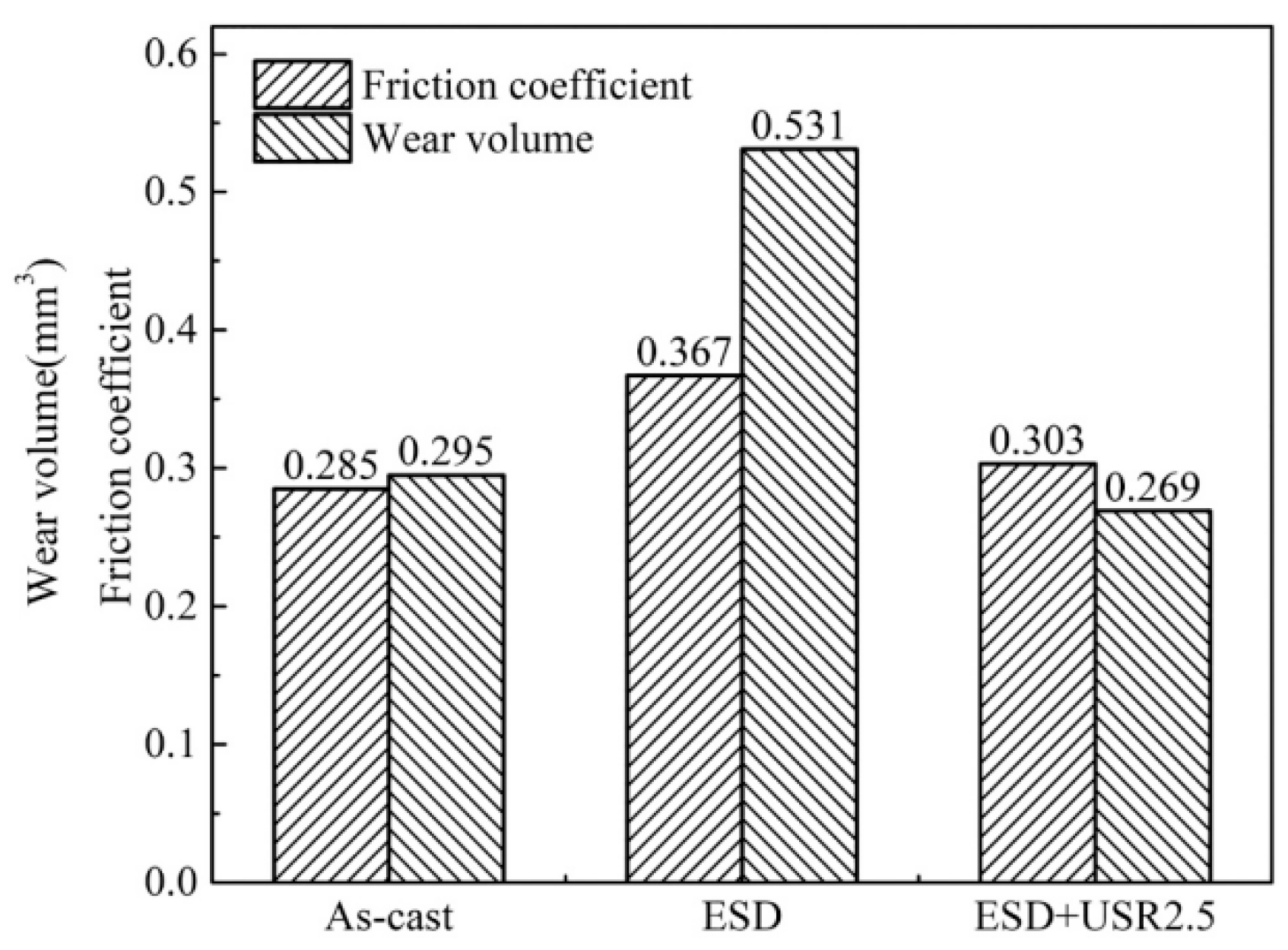
| ESD | Aluminum bronze | 2.0 GPa | - | - | Cu, Fe3Al, Cu3Al | - | 4.1~4.4 GPa | 0.303 | 0.269 mm3 | [53] |
| Copper | 77 HV | 0.226 | 465.28 × 10⁻⁶ mm3/N × m | FeAl, Cu, Fe3Al, TiO2 | 15~30 µm | 842 HV | 0.190 | 272.56 × 10⁻⁶ mm3/N × m | [54] | |
| Coating | Fe | C | B | Si | W | Ni | Cr | Mo | Co |
|---|---|---|---|---|---|---|---|---|---|
| First layer | Bal | 1.1 | 0 | 1.4 | 0 | 21.8 | 16.0 | 3.0 | 0 |
| Second layer | 8 | 1.5 | 0.6 | 2.4 | 4.5 | 13.0 | 23.0 | 0 | Bal |
| Coating | Current Intensity/A | Pulse Frequency/Hz | Scanning Speed/(mm·min−1) | Delivery Rate/(g·min−1) | Spot Diameter/mm | Lap Rate/% |
|---|---|---|---|---|---|---|
| First layer | 250 | 22 | 350 | 8.8 | 2.2 | 40 |
| Second layer | 250 | 22 | 400 | 11 | 2.0 | 50 |
| Experimental Temperature/℃ | Wear Rate (10−15 m3 (N⋅m)−1) | |
|---|---|---|
| Substrate | Coating | |
| 400 | 7.89 ± 1.25 | 4.24 ± 0.89 |
| 500 | 157.76 ± 15.33 | 74.33 ± 23.05 |
| 600 | 291.63 ± 40.10 | 129.48 ± 24.87 |
| Two-Step Method | Substrate | Coating | Ref. | |||||||
|---|---|---|---|---|---|---|---|---|---|---|
| Type | Hardness | COF | Wear Rate | Composition | Thickness | Hardness | COF | Wear Rate | ||
| Chemical Plating + Heat Treatment | C17200 | 340 HV | - | 3.03 × 10⁻⁶ mm3/N × m | Ni, Ni3P | 20~22 um | 998 HV | - | 2.04 × 10⁻⁶ mm3/N × m | [103] |
| ED + LCD | Copper | - | - | - | Mo, Ni3Mo, MoO2 | 600 um | 450 HV | - | - | [104] |
| LCD + In Situ synthesis | Copper | 48 HV0.2 | - | - | Cu, ZrB2, SiC | 1.3~1.9 mm | 309 HV0.2 | 0.2 | 30 mg/km | [105] |
| Friction Mode | Wear Rate Without Coating | Wear Rate with Coating | Percentage Decrease in Wear Rate | COF Without Coating | COF with Coating | Percentage Decrease in COF | Ref. |
|---|---|---|---|---|---|---|---|
| Pin disc friction | 6.3 mg | 1.4 mg | 77.8% | - | - | - | [103] |
| - | - | - | 0.45 | 0.24~0.33 | 26.7~46.7% | [32] | |
| - | - | - | 0.5 | 0.3 | 40.0% | [41] | |
| Ball disc friction | 465.28 × 10⁻⁶ mm3/N × m | 272.56 × 10⁻⁶ mm3/N × m | 41.4% | 0.226 | 0.190 | 15.9% | [54] |
| 4.24 × 10⁻⁴ mm3/N × m | 9.31 × 10⁻⁵ mm3/N × m | 78.1% | - | - | - | [29] | |
| 7.89~291.63 × 10⁻¹⁵ mm3/N × m | 4.24~129.48 × 10⁻¹⁵ mm3/N × m | 46.3~55.6% | - | - | - | [49] | |
| Rotary reciprocating wear test | 47 mg | 9.3 mg | 80.2% | - | - | - | [32] |
| Transverse sliding friction | 15.6 mg | 3.3 mg | 78.8% | 0.22 | 0.12 | 45.5% | [3] |
| Rolling contact fatigue friction | 15.4 mg | 3.0~3.9 mg | 74.7~80.6% | - | 0.11 | - | [35] |
| Ball flat reciprocating friction | - | - | - | 0.45 | 0.29 | 35.6% | [38] |
| 1.52~6.88 × 10⁻⁵ mm3/N × m | 1.24~4.12 × 10⁻⁵ mm3/N × m | 18.4~40.2% | 0.53~0.57 | 0.48~0.56 | 9.4~15.8% | [45] | |
| - | - | - | 0.9 | 0.3 | 66.7% | [46] | |
| 6.2 × 10⁻³ mm3/N × m | 1.1~2.6 × 10⁻³ mm3/N × m | 58.1~82.3% | 0.68 | 0.51 | 25.0% | [51] | |
| 3.03 × 10⁻⁶ mm3/N × m | 2.04 × 10⁻⁶ mm3/N × m | 32.7% | - | - | - | [103] | |
| 0.101 mm3 | 0.015 mm3 | 85.1% | 0.5901 | 0.4257 | 27.9% | [116] |
Disclaimer/Publisher’s Note: The statements, opinions and data contained in all publications are solely those of the individual author(s) and contributor(s) and not of MDPI and/or the editor(s). MDPI and/or the editor(s) disclaim responsibility for any injury to people or property resulting from any ideas, methods, instructions or products referred to in the content. |
© 2025 by the authors. Licensee MDPI, Basel, Switzerland. This article is an open access article distributed under the terms and conditions of the Creative Commons Attribution (CC BY) license (https://creativecommons.org/licenses/by/4.0/).
Share and Cite
Meng, F.; Zhou, Y.; Zhang, H.; Wang, Z.; Liu, D.; Cao, S.; Cui, X.; Nong, Z.; Man, T.; Liu, T. Development and Research Status of Wear-Resistant Coatings on Copper and Its Alloys: Review. Crystals 2025, 15, 204. https://doi.org/10.3390/cryst15030204
Meng F, Zhou Y, Zhang H, Wang Z, Liu D, Cao S, Cui X, Nong Z, Man T, Liu T. Development and Research Status of Wear-Resistant Coatings on Copper and Its Alloys: Review. Crystals. 2025; 15(3):204. https://doi.org/10.3390/cryst15030204
Chicago/Turabian StyleMeng, Fei, Yifan Zhou, Hongliang Zhang, Zhilan Wang, Dehao Liu, Shuhe Cao, Xue Cui, Zhisheng Nong, Tiannan Man, and Teng Liu. 2025. "Development and Research Status of Wear-Resistant Coatings on Copper and Its Alloys: Review" Crystals 15, no. 3: 204. https://doi.org/10.3390/cryst15030204
APA StyleMeng, F., Zhou, Y., Zhang, H., Wang, Z., Liu, D., Cao, S., Cui, X., Nong, Z., Man, T., & Liu, T. (2025). Development and Research Status of Wear-Resistant Coatings on Copper and Its Alloys: Review. Crystals, 15(3), 204. https://doi.org/10.3390/cryst15030204