Article

Corrosion Mechanism and Properties of 316L Stainless Steel in NaCl-KCl Molten Salt at High Temperatures

1
School of Nuclear Science and Technology, University of South China, Hengyang 421001, China
2
Shanghai Institute of Applied Physics, Chinese Academy of Sciences, Shanghai 201210, China
3
University of Chinese Academy of Sciences, Beijing 100049, China
4
Shanghai Synchrotron Radiation Facility, Shanghai Advanced Research Institute, Chinese Academy of Sciences, Shanghai 201210, China
5
School of Mathematics and Physics, University of South China, Hengyang 421001, China
*
Authors to whom correspondence should be addressed.
Crystals 2025, 15(3), 280; https://doi.org/10.3390/cryst15030280
Submission received: 13 February 2025 / Revised: 10 March 2025 / Accepted: 13 March 2025 / Published: 18 March 2025

Abstract

:
The corrosion properties of 316L stainless steel (316L SS) alloy within molten NaCl-KCl salt were explored through a static immersion experiment carried out at 700 °C under Ar flow for 25, 50, 100, 200, and 400 h. The loss in weight of the corroded 316L SS alloy increased from 0.06 to 1.71 mg/cm2, while the maximum corrosion depth increased from 1.71 to 14.09 μm. However, the corrosion rate initially increased from 27.54 μm/year to 93.45 μm/year and then decreased to 47.22 μm/year as the soaking time was increased from 25 to 400 h. The impurities in the molten salts produced corrosive Cl2 and HCl, which corroded the 316L SS matrix. The accelerated selective Cr dissolution with small amounts of Fe and Ni resulted in intergranular corrosion as the time of corrosion was increased. The depletion depths for Ni, Cr, and Fe at 400 h were found to be 0.87 μm, 3.94 μm, and 1.47 μm, respectively. The formation of Cr and Fe oxides might potentially play a vital role. The grain boundary and outward diffusion of Mo may prevent the outward diffusion of Cr, thereby mitigating alloy corrosion. Therefore, molten chloride salt purification and the selection of stainless steel are crucial for developing future concentrated solar power technologies. The findings of this study provide guidelines for the use of 316L SS in NaCl-KCl salt at high temperatures.

1. Introduction

Concentrated Solar Power (CSP) systems based on molten salt thermal storage hold significant potential for providing sustainable and efficient energy solutions [1,2]. As the performance of CSP stations depends largely on the working temperature of the molten salt, significant improvements in thermo-electric conversion efficiency can be achieved by raising the operational temperature of molten salts [3]. As CSP development involves both scientific and industrial aspects, the U.S. National Renewable Energy Laboratory (NREL) has recommended gradually increasing the working temperature of CSP [4]. The ultimate goal is to achieve an operating temperature of 700 °C, thereby minimizing the associated risks [5]. This challenge, however, lies in the limitation of current commercial molten salts such as eutectic nitrate salts like NaNO3-KNO3 (Tm = 221 °C) and NaNO3-KNO3-NaNO2 (Tm = 142 °C), which restrict their practical use within a temperature range of 295 °C to 565 °C [6,7]. To address these limitations, molten chloride salts have emerged as more promising candidates due to their higher melting points and superior thermal stability.
Compared with eutectic molten nitrate salt systems, eutectic molten chloride salt systems, such as NaCl-KCl (Tm = 657 °C) [8,9,10], NaCl-MgCl2 (Tm = 440.7, 445, and 459 °C) [11,12], KCl-MgCl2 (Tm = 425.8 °C) [13], NaCl-KCl-MgCl2 (Tm = 385.0 °C) [14,15,16], NaCl-KCl-ZnCl2 (Tm = 203, 204, 213, 229, and 250 °C) [17,18] NaCl-KCl-AlCl3 (Tm = 88.9 °C) [19], and NaCl-KCl-FeCl3 (Tm = 138.2 and 140.2 °C) [20], have been considered as suitable candidates for developing future generation CSP stations owing to their low price, excellent thermal stability at high temperature, high-efficiency heat transfer, and good heat storage. Among all eutectic molten chloride salt systems, NaCl-KCl has the lowest cost and is relatively easy to remove impurities (H2O and O2). In addition, molten NaCl-KCl salt has a high boiling point (above 1400 °C) and low vapor pressure (1:1 molar NaCl-KCl at 1110K: 1 torr) [21], which can reduce evaporation loss and corrosion of the structural materials caused by volatilization, lowering the potential security risks. Moreover, NaCl-KCl has a high melting point (Tm = 657 °C) and can maintain a stable molten state in ultra-high temperature environments, which can meet the high operating temperature of future generation CSP stations [22]. Nevertheless, the corrosion of structural materials used in CSP plants by molten chloride salts cannot be ignored and has attracted widespread attention [23].
Ni-based and Fe-based alloys, which exhibit high corrosion resistance (Rcor) in molten chloride salts and remarkable high-temperature mechanical characteristics, can be regarded as the most suitable structural materials for developing future CSP stations [24,25,26,27]. Compared with Ni-based alloys, Fe-based alloys are the preferred structural materials for future CSP stations owing to their lower prices. Among these Fe-based alloys, 304 stainless steel (304SS) and 316 stainless steel (316SS) are extensively used due to their high Rcor values, high-temperature performance, and relatively low cost. Therefore, many studies have reported the corrosion properties and associated mechanisms of 304SS and 316SS in molten chloride salts [28,29,30]. The corrosion rates (CR) of 304SS immersed within purified molten NaCl-MgCl2 salt under Ar flow at temperatures of 500 °C, 600 °C, and 700 °C were determined to be 74.50 μm/year, 86.13 μm/year, and 371.39 μm/year, respectively [13]. However, the CR values of 316SS measured by the same experimental method were 17.12 μm/year, 38.28 μm/year, and 205.36 μm/year at temperatures of 500 °C, 600 °C, and 700 °C, respectively. These values were lower than those of 304SS [11]. The corrosion of 304SS within purified molten NaCl-MgCl2 salt could primarily be related to the dissolution of Cr. The Cr diffusion process mainly occurred at grain boundaries (GBs), and the diffusion rate at the GBs increased with temperature, resulting in intergranular corrosion. In 304SS, the diffusion coefficient of Cr increased exponentially with an increase in temperature, thereby enhancing the severity of intergranular corrosion. Hence, the CR value of 304SS was higher compared to that of 316SS [11,13]. The corrosion mechanism and properties of 304SS and 316SS within NaCl-MgCl2-KCl molten salt inside a vacuum environment at a temperature of 700 °C were investigated by Liu et al. The CR values in this work were found to be 20,148 μm/year for 304SS and 11,388 μm/year for 316SS. This confirmed that the 316SS possessed a higher Rcor value once again [16]. They believed that the Rcor value of stainless steels would improve with a decrease in the Cr and Fe contents owing to the preferential dissolution of these elements. This is one reason why the 316SS exhibited a higher Rcor value than the 304SS. In addition, they found that adding a small amount of Mo to stainless steel was beneficial for mitigating corrosion. This is because Mo can facilitate surface passivation by producing insoluble Mo-containing compounds that inhibit localized corrosion. At high temperatures, Mo diffused outward to form a Mo-rich surface, which could slow the outward diffusion of Cr and Fe and delay the corrosion process. Therefore, it can be concluded that 316SS is more suitable than 304SS as structural materials for the future generation of CSP plants. However, the available literature on the corrosion properties of 316SS in NaCl-KCl molten salt at high temperatures is limited. Polovov et al. reported that 316L SS had a lower CR than 316Ti SS within molten NaCl-KCl salt at a temperature of 750 °C for 30 h and discussed the effect of carbon content on Rcor of stainless steels through the sensitization (precipitation of carbides along GBs) effect caused by high temperature [31]. The corrosion characteristics of 316SS in molten chloride salts are affected by many factors, such as the molten chloride salt system, operating temperature, and chemical composition; however, the corresponding influencing mechanisms are not well understood. Thus, the corrosion behavior of 316SS in molten chloride salts needs to be investigated further.
In this study, we selected 316L stainless steel and NaCl-KCl molten salt as the system for further investigation. According to the CSP development roadmap, new-generation CSP would operate at 700 °C; thus, this temperature was chosen for the corrosion resistance test. We conducted a series of static immersion corrosion tests to assess the corrosion rate (Rcor) of 316L SS in NaCl-KCl molten salt under rgon (Ar) flow at 700 °C. The weight loss method was used to determine the Rcor, and scanning electron microscopy (SEM), energy dispersive X-ray (EDX) analysis, and X-ray diffraction (XRD) were employed to examine the microstructure, elemental distribution, and morphology of the corroded surface and cross-section. The results indicate that 316L SS exhibits promising corrosion resistance in NaCl-KCl molten salt, which is critical for high-temperature CSP operation. Additionally, this study offers new insights into the corrosion mechanisms and the role of alloying elements, such as Cr and Mo, in enhancing corrosion resistance.
The findings of this study will contribute to the development of more durable materials for high-temperature CSP systems, thereby improving the efficiency and lifespan of future CSP plants. Further research is needed to explore the long-term behavior of 316L SS in NaCl-KCl molten salts, especially under operational conditions that closely resemble those found in real-world CSP systems.

2. Experimental Procedures

2.1. Materials Reparation

NaCl-KCl binary eutectic salt with a molar ratio of 1:1 was used as the experimental molten salt for the corrosion test. Analytical-grade NaCl and KCl obtained from Sinopharm Chemical Reagent Co., Ltd. (Shanghai, China), were used to prepare the salt mixture. The purchased salts were weighed according to the specified ratios. Subsequently, the salts were mechanically milled in an agate mortar. The thoroughly mixed salts were transferred to a quartz crucible and dried in a muffle furnace at 120 °C for 24 h. It should be noted that both the drying of the salt mixture and its storage before the experiment were performed inside a glove box under highly pure Ar gas flow (99.99%).
The chemical distribution of the experimental 316 L SS was analyzed using Spectro Arcos SOP inductively coupled plasma-optical emission spectroscopy (ICP-OES, SPECTRO Analytical Instruments GmbH, Kleve, Germany), as listed in Table 1. The 316L SS was shaped into samples measuring 20 mm × 10 mm × 2 mm utilizing an electric spark cutting machine. Subsequently, the samples were ground to a 3000-grit finish with SiC paper and polished with 0.05 μm Al2O3 powder [32]. An Al2O3 crucible was selected as the container for the corrosion process due to its chemically inert nature to molten chloride salts. The polished 316L SS specimens and Al2O3 crucibles were ultrasonically cleaned with deionized water and alcohol, followed by thorough drying.

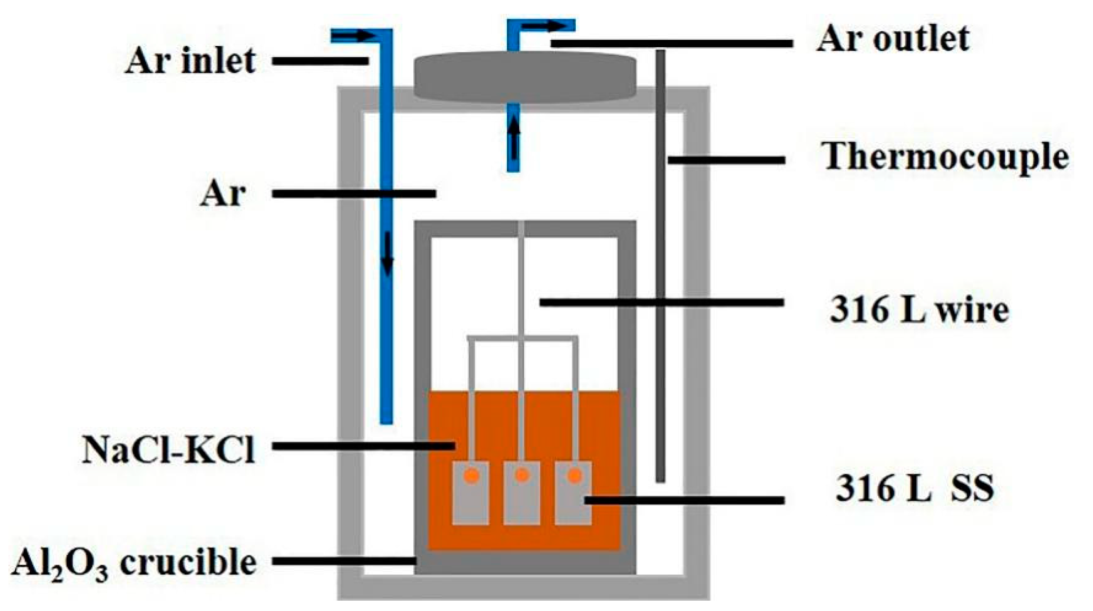
2.2. Corrosion Experiment

The static corrosion testing device is depicted in Figure 1. The prepared specimens of 316L SS were suspended across the holes in the crucible cover using a 316L SS wire. It was ensured that the 316L SS samples did not touch the bottom of the Al2O3 crucible. A total of 100 g of solid NaCl-KCl salt was ground, mixed, and transferred to an Al2O3 crucible to completely bury the 316L SS samples. A high-temperature glue was used to seal up the joint between the crucible and its cover, as well as the holes in the cover of the crucible, to ensure complete bonding. Three 316L SS specimens were placed in each Al2O3 crucible. A glove box with a highly pure Ar gas flow was used to conduct all the above operations, where the concentrations of O2 and H2O were below 10 ppm.
The sealed Al2O3 crucibles were divided into five groups and placed in a muffle furnace for static corrosion experiments. Each group was subjected to different heating durations in a heating furnace. According to the operating temperature requirements of the next generation of CSP stations, the furnace was first heated to 300 °C for 48 h to ensure that the molten NaCl-KCl salt dried completely. Subsequently, the furnace temperature was further increased to 700 °C and kept for 25 h, 50 h, 100 h, 200 h, and 400 h in the five different groups, respectively. The sealed Al2O3 crucibles were allowed to cool in the furnace. Subsequently, the 316L SS specimens were removed from the sealed Al2O3 crucibles. The obtained samples were rinsed with ethanol and deionized water to remove residual salt and moisture and finally dried at 180 °C for 12 h. Photographs of the dried 316L SS samples are exhibited in Figure 2. Before the static corrosion experiment, the surface of the 316L SS specimen was extremely flat and could produce a mirror reflection effect, as shown in Figure 2a. The surfaces of the specimens immersed for 25 h and 50 h were relatively light and flat, while those of the specimens immersed for 100 h to 400 h displayed a dim metallic color and became rough. Nonetheless, no pitting, peeling, or detachment caused by localized corrosion was observed on the surface of the specimens, indicating no delamination. Thus, it could be considered that the corrosion of 316L SS within molten NaCl-KCl salt was uniform.

2.3. Characterization

In an experiment involving static corrosion, 316L SS samples were weighed before and after the experiment using an electronic balance with a precision of 0.1 mg. The change in weight per unit area can be calculated using the following equation [33]:
W = m 0 m 1 S
where W represents the weight loss per unit area (mg/cm2), S represents the surface area of the alloy specimens (cm2), m0 represents the initial weight of the alloy specimens (mg), and m1 represents the weight of the corrosion-damaged alloy specimens after cleaning and drying (mg). The value of CR (μm/year) under uniform corrosion can be calculated using the following equation [34]:
C R = K × W t × ρ
where K represents a coefficient (8.76 × 10⁴), t denotes the time of corrosion of the specimen in the molten salt (h), and ρ represents the density of the alloy specimen (g/cm3). The value of ρ for the 316L SS was determined by Archimedes’ principle using a thin coating of Vaseline to prevent water permeation, and the measured value was 7.95 g/cm3. The weight loss and the value of CR reported herein were obtained by averaging the values for the three separate 316L SS alloy specimens under the same test conditions.
The cross-sectional and surface images of the prepared specimens were obtained utilizing Scanning electron microscopy (SEM, Merlin Compact; Carl Zeiss AG, Oberkochen, Germany) system integrated with an X-Max EDS (80 mm2; Oxford Instruments, Abingdon, UK). To analyze the concentrations of primary metal ions within the molten NaCl-KCl salt post-corrosion, an ICP-OES system (SPECTRO Analytical Instruments GmbH, Kleve, Germany). was employed. The crystal phases of the 316L SS on the surface before and after corrosion were identified using a X-ray diffractometer (XRD, D8 Advance; Bruker Corporation, Karlsruhe, Germany) with a Cu Kα radiation source (λ = 1.5406 Å). The prepared samples were scanned from 20° to 90°, operating at 40 kV and 40 mA, with a step length of 0.02° (continuous PSD fast scanning mode).

3. Result and Discussion

3.1. Corrosion Properties

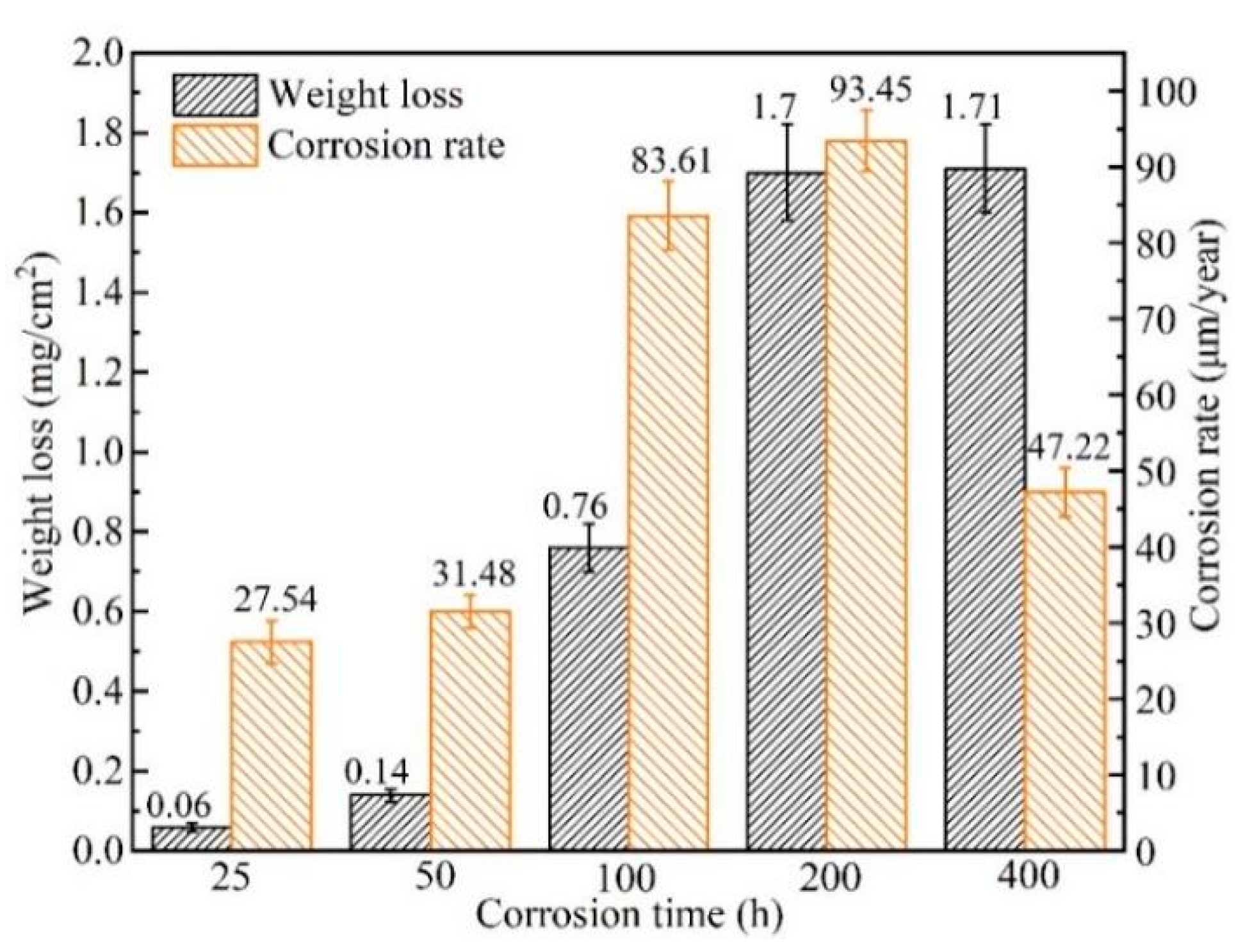
3.1.1. Weight Change

The weight changes and corrosion rates (CR) of the 316L stainless steel (SS) alloy after immersion in molten NaCl-KCl salt under an Ar flow at 700 °C for various durations are shown in Figure 3. The weight loss of the corroded 316L SS alloy increased with increasing immersion time. Specifically, the weight loss was 0.06 mg/cm2 at 25 h, which sharply increased to 1.70 mg/cm2 at 200 h. At 400 h, the weight loss reached 1.71 mg/cm2, which was nearly the same as that at 200 h.
The observed weight change in the corroded 316L SS specimens during static corrosion can be attributed to two primary factors: (i) weight loss due to the selective dissolution of elements in the 316L SS, such as chromium (Cr), and (ii) weight gain from the formation of corrosion products, such as Cr2O3 and Fe2O3, on the corroded surface. It is important to note that the NaCl and KCl salts used in this experiment contained impurities, including O2 and H2O, which likely reacted with the 316L SS alloy to form compounds like Cr2O3 and Fe2O3. These products could have a significant impact on the corrosion behavior of the alloy [35]. All corroded 316L SS specimens exhibited weight loss after static corrosion over different time intervals. Therefore, it can be concluded that selective dissolution was the dominant mechanism driving corrosion in this study.
The value of CR was determined by tracking the variation in weight based on uniform static corrosion [36]. The calculated CR values for the corroded 316L SS alloy specimens initially increased and then decreased with an increase in the immersion time. The CR value for the corroded 316L SS alloy reached a maximum value of 93.45 μm/year at an immersion time of 200 h, which was about 3.4 times its value at 25 h. However, the value of CR for the corroded 316L SS alloy decreased to 47.22 μm/year at 400 h, which was about half of the CR value at 200 h. The increase in the value of CR at the initial stage of static corrosion might be related to the oxidizing impurities within the molten NaCl-KCl salts [16,37]. In general, metal materials can corrode easily owing to the presence of trace amounts of H2O molecules within molten chloride salts, resulting in the dissolution of alloying elements and accelerating corrosion [24]. In addition, oxidized impurities, HCl and Cl2, are produced due to the decomposition of molten NaCl-KCl salt at high temperatures [38]. The produced HCl and Cl2 could react with the alloying elements (Ni, Fe, and Cr) within the 316L SS specimen and increase the CR value. The CR value decreased when impurities within the molten chloride salts were almost consumed. The CR values for the 316 SS alloys in various eutectic molten chloride salt systems, as found in previous studies, are listed in Table 2 [11,18,23,38]. It was evident that the CR value for the 316 SS specimen within the molten NaCl-KCl salt system was lower in comparison to that in other molten chloride salt systems, while also demonstrating a remarkably high value of Rcor at high temperatures within this particular salt system.

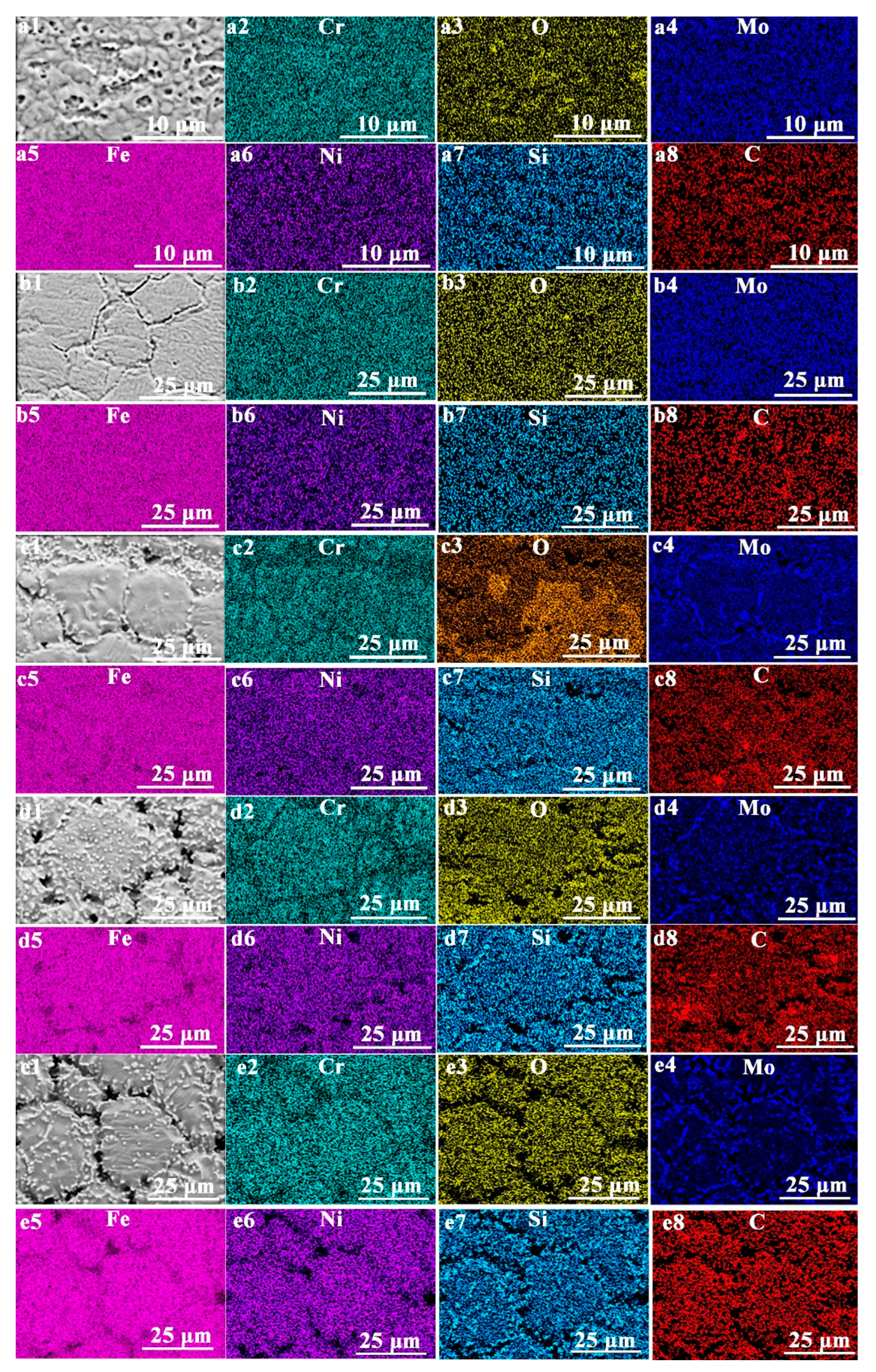
3.1.2. Elemental Distribution and Surface Morphology

The SEM-EDS image of the 316L SS specimen is shown in Figure 4. The sizes of 500 grains were measured using the Nano Measurer 1.2 software (College of Chemistry and Chemical Engineering, Fudan University, Shanghai, China) to determine the average grain size. The mean grain size of the experimental 316L SS alloy was approximately 23.92 μm, with an error range of ±17.94 μm. In addition to a small amount of δ phase, no significant precipitated phases were observed along the grain boundaries (GB). However, a few discontinuous sub-micron precipitates were clearly visible within the grains. These sub-micron precipitates were identified as the M23C6 phase [3].
The surface morphologies of the 316L SS specimens immersed in molten NaCl-KCl salt at 700 °C for various durations are shown in Figure 5. After 25 h of immersion, slight scratches from grinding and pits caused by corrosion were observed on the surface, indicating that the alloy primarily underwent pitting corrosion. As the immersion time increased from 50 h to 400 h, significant intergranular corrosion developed. The extent of corrosion at the grain boundaries (GBs) increased with longer immersion times, and after 200 h and 400 h, the GBs were nearly completely corroded, resulting in the loosening of grains. After 400 h of immersion, some cracks between the grains widened to over 4 μm, indicating severe intergranular corrosion. Additionally, white particles with diameters less than 2 μm appeared on the surface of the 316L SS specimen after 100 h of immersion, as shown in Figure 5e–j. These particles are likely to be corrosion products or precipitates originating from the salt.
The elemental compositions of the corroded 316L SS specimens, as well as the areas marked A, B, C, and D in Figure 5, were analyzed using SEM-EDS, and the results are presented in Table 3. The elemental distribution varied among the specimens corroded for different durations. Notably, the Cr content in all the corroded specimens was lower than that in the non-corroded 316L SS specimen (see inset in Figure 4), while the Mo content on the surface increased with immersion time. This suggests that the 316L SS experienced de-Cr corrosion in the NaCl-KCl molten salt. Generally, the loss of Cr tends to result in a high carbon content around the corrosive pits [38], as shown in Figure 5b and Table 3. Furthermore, it was confirmed that Mo exhibits better corrosion resistance than Cr in NaCl-KCl molten salts.
The areas marked A, B, C, and D in Figure 5 were found to be enriched in C and O, indicating that these regions might contain carbides and oxides. The plots of the change in Gibbs free energy (ΔG) of the corresponding carbides and oxides with temperature are presented in Figure 6. The value of ΔG was determined using the equation ΔGT = ΔHT + TΔST, utilizing the thermodynamic software of HSC Chemistry 6.0 (Metso Outotec, Espoo, Finland), where ΔGT denotes the value of ΔG at T K, and ΔST and ΔHT represent the differences in entropy and enthalpy of the reaction to the reactants at T K, respectively [39]. For a true comparison, the Ellingham−Richardson diagram was used, and it was computed from thermodynamic calculations, as shown in Figure 6 [40,41]. Combined with Table 3 and Figure 6, the region marked with A was a corrosive pit, and the corrosive products covered in the pit might have been Cr2O3. The bright particles marked B, C, and D in Figure 5 gathered Si and Mo, and the contents of C and O were also significantly higher compared to those in other regions. According to the calculated value of G, it could be concluded that the bright particles might be molybdenum/silicon oxides.
The elemental distributions of the corroded 316L SS specimens were captured using SEM-EDS, as shown in Figure 7. For the specimens immersed in molten NaCl-KCl salts at 700 °C for 25 h and 50 h, the elements Fe, Ni, Mo, Cr, Si, C, and O were relatively evenly distributed across the surface, indicating that the 316L SS specimens experienced uniform corrosion. However, after immersion for 100 h, Cr depletion and Mo enrichment began to appear at the grain boundaries (GBs). Furthermore, the severity of Cr depletion and Mo enrichment at the GBs increased with longer immersion times. These observations suggest that Mo could diffuse from the grains to the corroded GBs during the corrosion process. A similar phenomenon was reported by Luo et al. when the Inconel 617 alloy was corroded in LiF-MgF2-KF molten salts [42]. They suggested that Cr depletion leads to the formation of numerous vacancies, and the concentration gradient of vacancies between the grains and corroded regions serves as the driving force for Mo diffusion. Consequently, the Mo content was higher near the corroded regions. Sun et al. also reported that small amounts of continuous Mo-rich carbides (marked B, C, and D in Figure 5) along the GBs tend to reduce corrosion [34]. Additionally, noticeable depletion of Fe, Ni, and O at the GBs was observed, suggesting that the corroded 316L SS specimens were covered with Fe, Ni, and Cr oxides.

3.1.3. Crystalline Structure

The obtained XRD spectra of the 316L SS specimen prior to and following corrosion in molten NaCl-KCl salts at a temperature of 700 °C for various time durations are shown in Figure 8. The Cr0.19Fe0.7Ni0.11 phase (PDF card 33-0397, face-centered cubic structure, a = 3.5911 Å) was the main crystalline phase for the 316L SS specimen before corrosion and was also detected after corrosion. Compared with the diffraction peak intensity of the Cr0.19Fe0.7Ni0.11 phase for the 316L SS sample prior to corrosion, the diffraction peak intensity for the 316L SS sample following corrosion was weaker, which could be linked to the formation and coverage of corrosive products. New peaks of 2θ at around 44.65°, 64.98°, and 82.28° were observed on the surface of the corroded 316L SS specimens, which were consistent with the characteristic signal of the Fe-Ni phase (PDF card 37-0474, body-centered cubic structure, a = 2.8681 Å). In addition to the Cr0.19Fe0.7Ni0.11 and Fe-Ni phases, the diffraction peak of Cr2O3 (PDF card 85-0730) was also observed after immersion for 100 h. When the 316L SS specimen was immersed in the NaCl-KCl molten salt for 400 h, Fe2O3 (PDF card 54-0489) was observed in the XRD pattern. The obtained XRD results agreed with the thermodynamic calculations of the oxides and elemental analysis of the corroded samples.

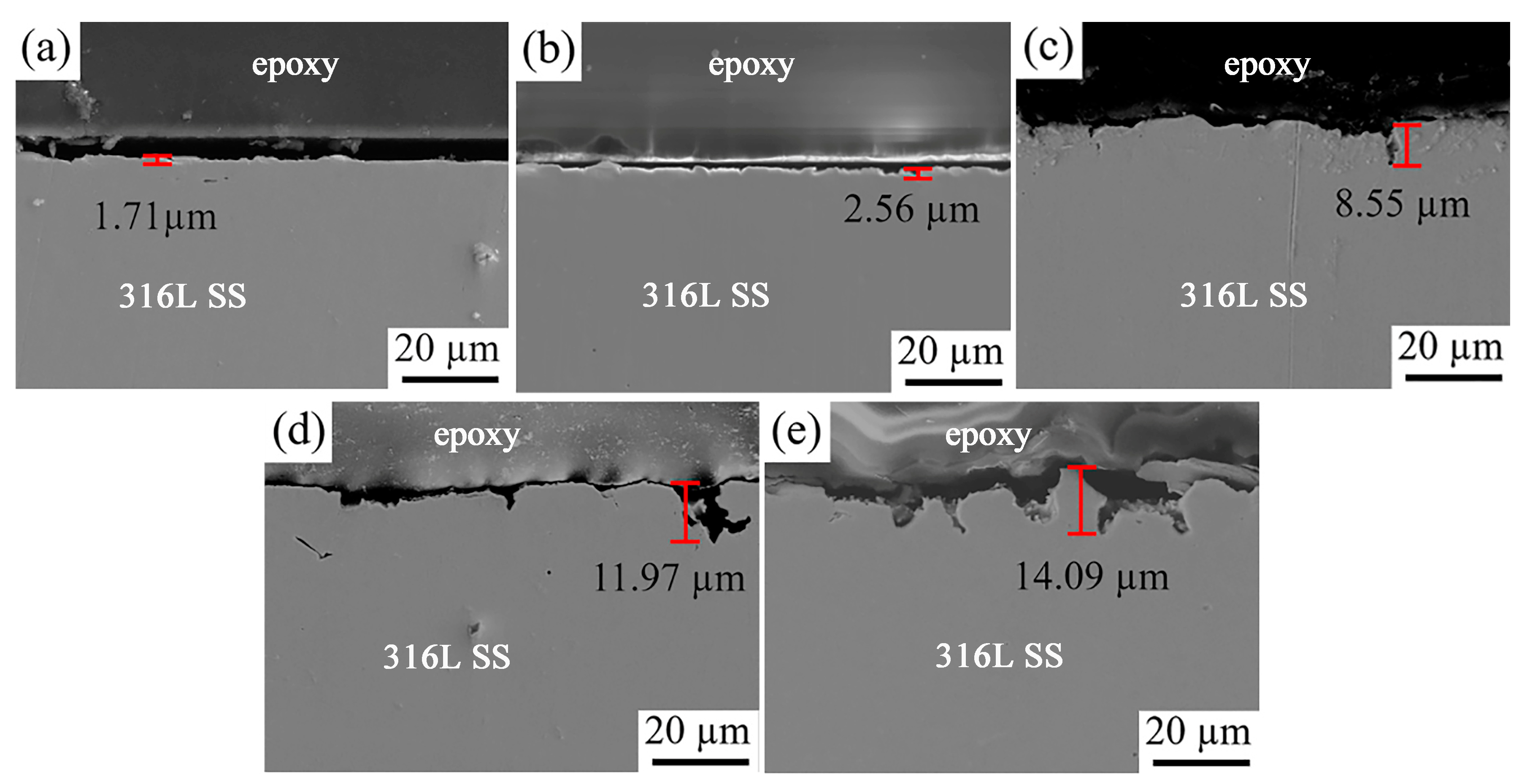
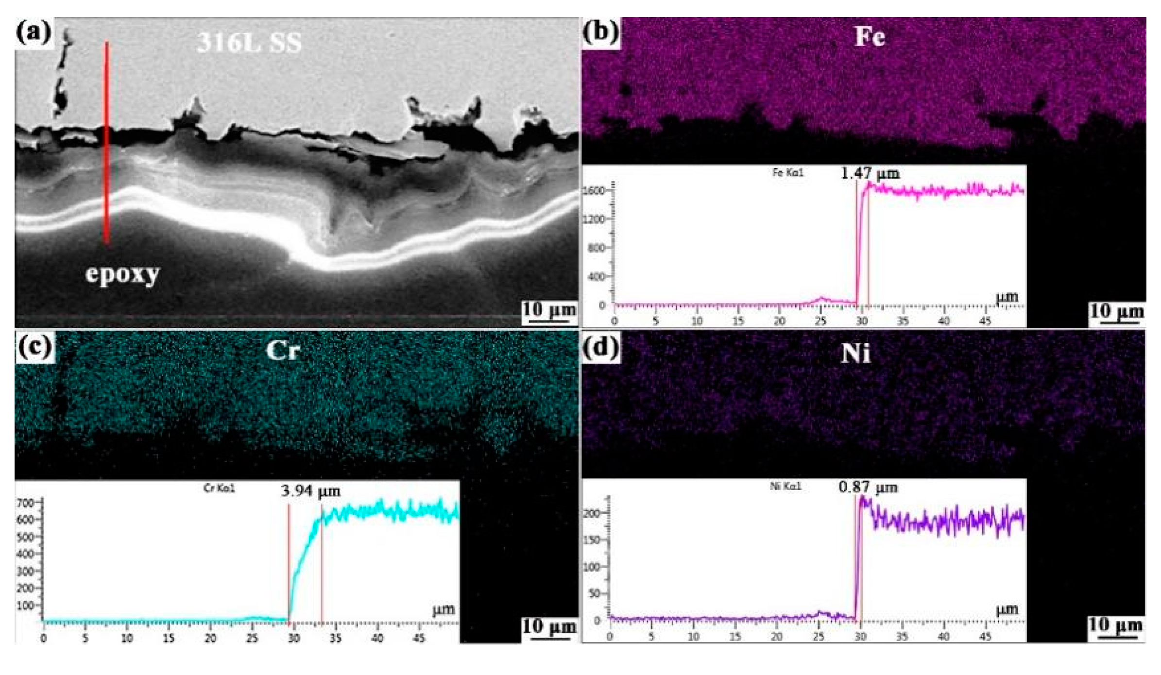
3.1.4. Elemental Distribution and Cross-Sectional Morphology

The cross-sectional morphologies of the 316L SS specimens immersed in the NaCl-KCl molten salt at a temperature of 700 °C for various time durations are illustrated in Figure 9. The cross-sectional surface of the corroded 316L SS alloy after immersion for 25 h was flat, with no obvious corrosion. The maximum corrosion depth was as low as 1.71 μm. It must be emphasized that the maximum corrosion depth in this work was obtained by measuring the distance between the surface and the deepest attack on the corroded 316L SS alloy during corrosion. The maximum corrosion depth increased as the corrosion time increased. The surface of the corroded 316L SS alloy became uneven after immersion for 50 h, and the maximum corrosion depth increased to 2.56 μm. Its value reached 8.55 μm when the value of t was extended to 100 h, and intergranular corrosion was observed. The surface of the corroded 316L SS alloy deteriorated as the time duration was increased to 400 h. The corrosion degree increased substantially, and the value of the maximum corrosion depth increased to 14.09 μm.
The cross-sectional SEM-EDS mappings of the primary elements for the 316L SS specimen immersed in molten NaCl-KCl at 700 °C for 400 h are shown in Figure 10. It was clearly observed that the specimen experienced Cr depletion, which predominantly occurred along the grain boundaries (GBs). In addition, Fe depletion was also detected at the GBs. To assess the compatibility of the 316L SS specimen with molten NaCl-KCl salt, the depletion depths of Cr, Ni, and Fe were measured, as shown in the insets in Figure 10b–d. The depletion depths were found to be 1.47 μm for Fe, 3.94 μm for Cr, and 0.87 μm for Ni. These results further confirm that the corrosion of the 316L SS specimen in NaCl-KCl molten salt was primarily due to selective Cr dissolution, accompanied by the dissolution of small amounts of Fe and Ni. The Cr depletion depth can be used as an indicator of intergranular corrosion penetration.

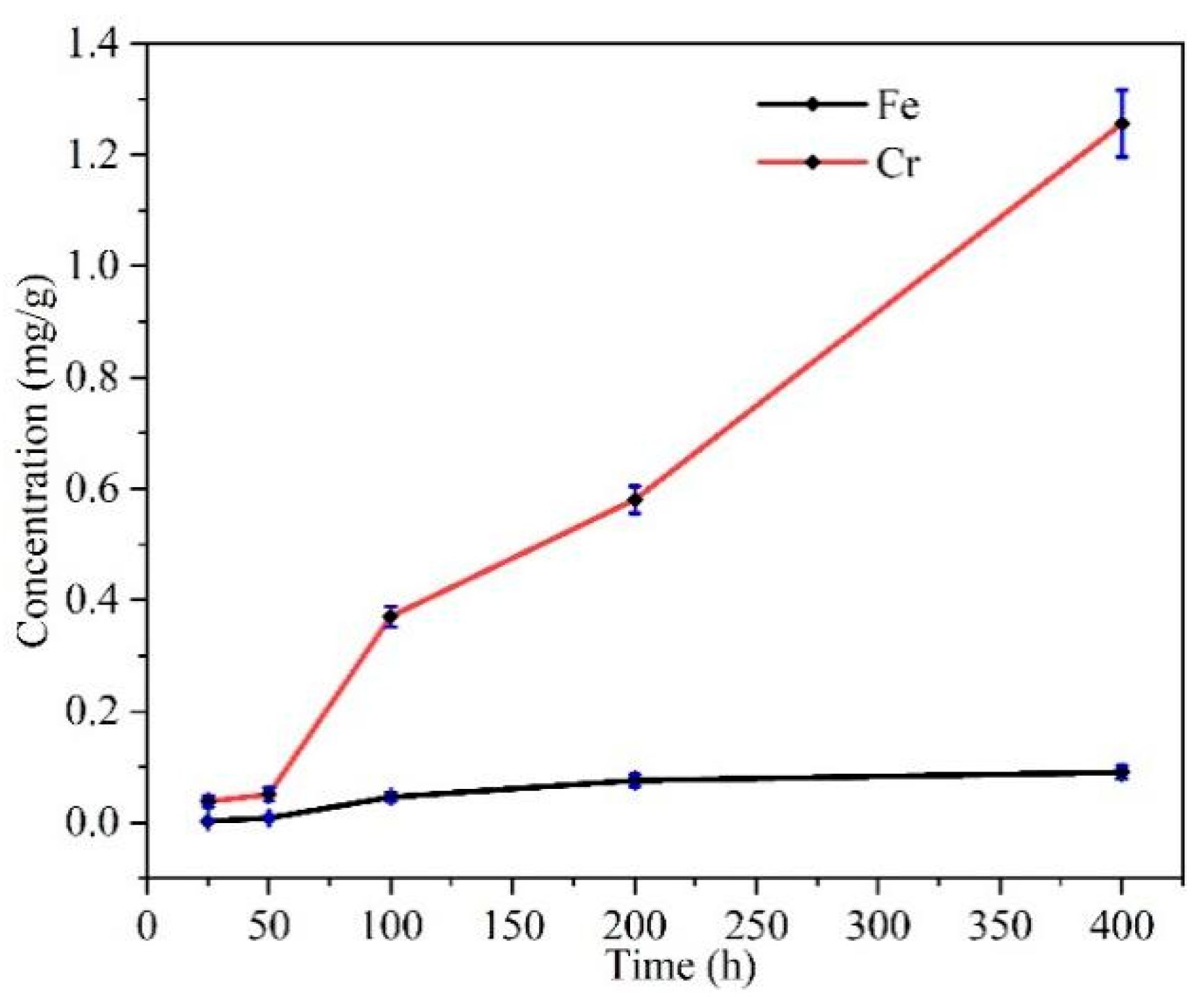
3.1.5. Cr and Fe Concentration in the Molten Salt After Corrosion

The variation in concentration values of Cr and Fe in the molten NaCl-KCl salt with immersion time is depicted in Figure 11. The figure clearly shows an increase in the concentration of both elements with an increase in immersion time. From 50 h to 100 h of immersion, there was a sharp increase in the Fe and Cr concentrations, indicating a significant loss of Fe and Cr from the 316L SS specimens. Subsequently, the concentration of Fe within the molten salt slowly increased as the immersion time was extended from 100 to 400 h, whereas the concentration of Cr increased almost linearly with immersion time. Since the concentration values of Ni, Cr, Mo, and Fe within the 316L SS specimen were much higher than those in the NaCl-KCl molten salt, the concentration difference resulted in the diffusion of these elements from the 316L SS specimen to the molten salt. However, among these elements, Cr was the element that corroded most easily, whether in molten chloride or fluoride salts, because Cr exhibits the fastest diffusion rate and the highest chemical activity [33]. Hence, the dissolution and loss of Cr was the most serious, followed by that of Fe. It should be pointed out that the amount of dissolution and loss of Ni and Mo from the 316L SS specimen was so small that the Ni and Mo concentrations in the molten salt could not be determined using ICP-OES.

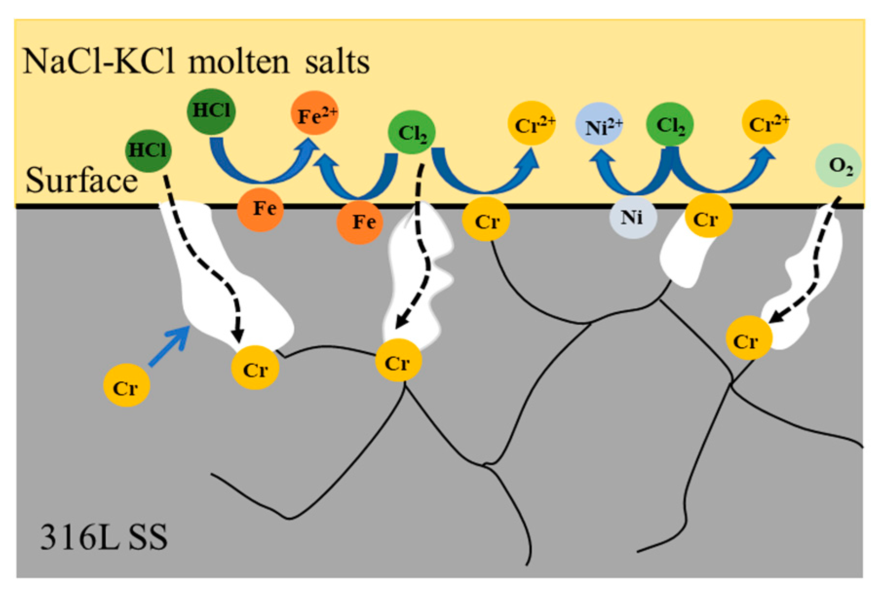
3.2. Corrosion Mechanism Analysis

According to the XRD results, it is certain that Fe and Cr in the 316L SS specimens participated in the reaction to generate the corresponding oxides. It had been confirmed that the corrosion of the 316L SS specimens within the molten chloride salts at high-temperature values was related to the contaminants present within the molten salts, such as O2 and H2O [43,44]. O2 and H2O would react with Cl from molten chloride salts to produce Cl2, HCl, and O2−, and the reactions can be written as follows:
2 C l + O 2 g = C l 2 g + O 2
H 2 O + 2 C l = 2 H Cl g + O 2
Moreover, the O2 would also react with the 316L SS alloy matrix to form an oxide layer. The produced Cl2 could react with the 316L SS alloy matrix to generate chlorides. HCl gas obtained by the hydrolysis of molten chloride salts would dissolve into the NaCl-KCl molten salts and corrode metal elements such as Fe, Ni, and Cr. Therefore, O2, HCl, and Cl2 would have crucial effects on the corrosion behavior of 316 L SS alloys within molten NaCl-KCl salts, which can be evaluated using a thermodynamic technique. The Gibbs free energies for the possible reactions were obtained using HSC Chemistry 6.0 thermodynamics software, and the obtained values are provided in Table 4. The results showed that the value of ΔG for the formation of (Fe, Cr, Ni)Cl2 increased in the order CrCl2 < FeCl2 < NiCl2. This tendency indicates that Cr has the worst stability against the NaCl-KCl molten salt compared with Fe and Ni. Thus, it can be deduced that Cr is preferentially attacked by molten chloride salts, followed by Fe and Ni [45]. These findings suggest that the primary corrosion chemical reactions of the 316L SS specimens in the NaCl-KCl molten salt were as follows:
Cr + C l 2 ( g ) = CrC l 2
Cr + 2 HCl ( g ) = CrC l 2 + H 2 ( g )
Hence, the 316L SS underwent selective Cr dissolution, producing soluble CrCl2 in the molten NaCl-KCl salt, which led to the formation of subsurface voids and consequently weight loss. Conversely, Cr and the formed CrCl2 could be oxidized to form Cr2O3, which adhered to the surface of the 316L SS specimen, causing weight gain. However, the CrCl2 content was much higher than the Cr2O3 content due to the limited amount of O2 in the molten salt, resulting in an overall weight loss of the 316L SS specimens during static corrosion.
Similarly, Ni and Fe could also be selectively attacked, forming soluble NiCl2 and FeCl2 in the NaCl-KCl molten salt. This process contributed to the depletion of Ni and Fe in the cross-section of the 316L SS specimens. Based on the calculated Gibbs free energy (ΔG) values, the amount of NiCl2 formed was smaller than that of FeCl2, indicating that Fe experienced more significant dissolution than Ni. Therefore, the depletion of Ni was less pronounced than that of Fe, suggesting that Ni underwent only slight dissolution. The possible chemical reactions for the dissolution of Fe and Ni are as follows:
F e + C l 2 ( g ) = F e C l 2
F e + 2 H CL ( g ) = F e C l 2 + H 2 ( g )
N i + C l 2 ( g ) = N i C l 2
The calculated Gibbs free energies of O2 reacting with Cr and CrCl2 to form Cr2O3 were −1756.17 kJ/mol and −652.28 kJ/mol, respectively, which were larger than that of O2 reacting with Ni to form NiO (−301.81 kJ/mol). The calculated ΔG value of O2 reacting with NiCl2 to form NiO was 17.61 kJ/mol, indicating that this chemical reaction could not occur. Hence, Cr2O3 was preferentially formed, followed by Fe2O3 and finally NiO. The possible chemical reactions are as follows:
4 C r + 3 O 2 ( g ) = 2 C r 2 O 3
4 F e + 3 O 2 ( g ) = 2 F e 2 O 3
4 F e C l 2 + 3 O 2 ( g ) = 2 F e 2 O 3 + 4 C l 2 ( g )
2 N i + O 2 ( g ) = 2 NiO
However, NiO was not detected in the corroded specimens using XRD, as shown in Figure 8. This can be explained by the following two reasons: (i) the NiO content was so low that the diffraction peak was too weak to be detected, and (ii) there was not enough O2 to participate in the reaction (14) and form NiO.
Based on the above analysis, schematic diagrams illustrating the corrosion mechanism of the 316L SS alloy in molten NaCl-KCl salt are presented in Figure 12. The selective dissolution of Cr was identified as the primary cause of the corrosion of 316L SS alloys in molten chloride salts. Specifically, Cr atoms located on the surface and along the grain boundaries (GBs) preferentially dissolved. Consequently, the diffusion rate of Cr atoms played a crucial role in the corrosion behavior of the 316L SS alloy. Smith et al. observed that the diffusion rate of Cr atoms along the GBs in 316L SS was faster than that in the lattice [46]. The GBs of the 316L SS alloy preferentially corroded in NaCl-KCl molten salt, resulting in intergranular corrosion. Additionally, the δ phase and M23C6 phase (as shown in Figure 4) within the 316L SS alloy might dissolve in the NaCl-KCl molten salt, causing pitting corrosion. Corrosion pits can act as stress concentrators, potentially exacerbating the propagation of intergranular corrosion. Moreover, small amounts of Mo content in stainless steels may suppress pitting corrosion [34]. Therefore, both intergranular corrosion and pitting corrosion were observed in the 316L SS alloy within the NaCl-KCl molten salt environment; however, intergranular corrosion was the predominant corrosion mechanism.

4. Conclusions

The corrosion behavior of the 316L SS alloy immersed in molten NaCl-KCl salt was investigated under Ar flow at 700 °C for various time durations. The study revealed that the corrosion depth and weight loss of the corroded 316L SS alloy increased with an increase in the value of t. However, the CR value of the corroded 316L SS alloy reached a peak value of 93.45 μm/year at 200 h and decreased significantly to 47.22 μm/year at 400 h. The molten NaCl-KCl salt exhibited the weakest corrosivity on the 316 SS alloy compared to molten NaCl-MgCl2, NaCl-KCl-MgCl2, and NaCl-KCl-ZnCl2 salts. The selective dissolution of the matrix alloying element to form soluble chlorides in the molten salt was primarily caused by the impurities of O2 and H2O from the molten NaCl-KCl salt, which resulted in the generation of subsurface voids and weight loss. The main mechanism of corrosion for the 316L SS alloy within molten NaCl-KCl salt was intergranular corrosion owing to the dissolution of Cr and small amounts of Fe and Ni on the GBs. These findings provide useful values and guidelines for molten salt and material selection that may aid in developing next-generation CSP stations.

Author Contributions

R.L.: Analysis and interpretation of the data; Drafting the manuscript. J.C.: Writing-reviewing; Editing and revising. X.T.: Revising the manuscript critically for important interllectual content. Z.Y.: Formal analysis; validation. H.A.: Data curation. H.S.: Formal analysis; validation. W.Z.: Visualization. Y.W.: Investigation. L.Y. All authors have read and agreed to the published version of the manuscript.

Funding

This research was supported by Xian Tang, Long Yan, Ying Wang and Jinjuan Cheng. This study was funded by the National Natural Science Foundation of China (Grant Nos. 12175302 and 11675246) and the Science and Technology Innovation Program of Hunan Province (No. 2021RC3105), and the Open Project of Guangxi Key Laboratory of Nuclear Physics and Nuclear Technology (No. NLK2021-06), and the Natural Science Foundation of Hunan Province (No. 2023JJ30512). This work was endorsed by the User Experiment Assist System of the Shanghai Synchrotron Radiation Facility.

Data Availability Statement

Detailed data related to this study can be provided by the corresponding author upon reasonable request.

Conflicts of Interest

The authors declare no conflicts of interest.

Abbreviations

The following abbreviations are used in this manuscript:
MDPIMultidisciplinary Digital Publishing Institute
DOAJDirectory of open access journals
TLAThree letter acronym
LDLinear dichroism

References

  1. Guillot, S.; Faik, A.; Rakhmatullin, A.; Lambert, J.; Veron, E.; Echegut, P.; Bessada, C.; Calvet, N.; Py, X. Corrosion effects between molten salts and thermal storage material for concentrated solar power plants. Appl. Energy 2012, 94, 174–181. [Google Scholar] [CrossRef]
  2. Vignarooban, K.; Xu, X.H.; Arvay, A.; Hsu, K.; Kannan, A.M. Heat transfer fluids for concentrating solar power systems—A review. Appl. Energy 2015, 146, 383–396. [Google Scholar] [CrossRef]
  3. Li, X.L.; Chang, L.T.; Liu, C.P.; Leng, B.; Ye, X.X.; Han, F.F.; Yang, X.M. Effect of thermal aging on corrosion behavior of type 316H stainless steel in molten chloride salt. Corros. Sci. 2021, 191, 109784. [Google Scholar] [CrossRef]
  4. Turchi, S.; Vidal, J.; Bauer, M. Molten salt power towers operating at 600–650 °C: Salt selection and cost benefits. Sol. Energy 2018, 164, 38–46. [Google Scholar] [CrossRef]
  5. Castro-Quijada, M.; Faundez, D.; Rojas, R.; Videla, A. Improving the working fluid based on a NaNO3-KNO3-NaCl-KCl molten salt mixture for concentrating solar power energy storage. Sol. Energy 2022, 231, 464–472. [Google Scholar] [CrossRef]
  6. Bonk, A.; Sau, S.; Uranga, N.; Hernaiz, M.; Bauer, T. Advanced heat transfer fluids for direct molten salt line-focusing CSP plants. Prog. Energy Combust. Sci. 2018, 67, 69–87. [Google Scholar] [CrossRef]
  7. Walczak, M.; Pineda, F.; Fernández, Á.G.; Mata-Torres, C.; Escobar, R.A. Materials corrosion for thermal energy storage systems in concentrated solar power plants. Renew. Sustain. Energy Rev. 2018, 86, 22–44. [Google Scholar] [CrossRef]
  8. Gore, P.; Singh, M.P.; Suryateja, D.; Basu, B.; Chattopadhyay, K. Early-stage corrosion of IN 740H alloy in eutectic NaCl-KCl molten salt at high temperatures. Sol. Energy 2023, 252, 330–341. [Google Scholar] [CrossRef]
  9. Grégoire, B.; Oskay, C.; Meißner, T.; Galetz, M.J. Corrosion mechanisms of ferritic-martensitic P91 steel and Inconel 600 nickel-based alloy in molten chlorides. Part I: NaCl–KCl binary system. Sol. Energy Mater. Sol. Cells 2020, 215, 110659. [Google Scholar] [CrossRef]
  10. Salinas-Solano, G.; Porcayo-Calderon, J.; Gonzalez-Rodriguez, J.G.; Salinas-Bravo, V.M.; Ascencio-Gutierrez, J.A.; Martinez-Gomez, L. High Temperature Corrosion of Inconel 600 in NaCl–KCl Molten Salts. Adv. Mater. Sci. Eng. 2014, 2014, 696081. [Google Scholar] [CrossRef]
  11. Guo, L.L.; Liu, Q.; Yin, H.Q.; Pan, T.J.; Tang, Z.F. Excellent corrosion resistance of 316 stainless steel in purified NaCl–MgCl eutectic salt at high temperature. Corros. Sci. 2020, 166, 108473. [Google Scholar] [CrossRef]
  12. Lu, P.F.; Guo, L.L.; Liu, Q.; Liu, L.L.; Pan, T.J.; Tang, Z.F. Excellent high temperature corrosion resistance of 304 stainless steel immersed in purified NaCl–MgCl2 eutectic salts. Mater. Chem. Phys. 2023, 296, 127216. [Google Scholar] [CrossRef]
  13. Lin, Z.Q.; Zhao, Z.X.; Song, J.L.; Tang, Z.F.; Tao, Z.C.; Liu, Z.J.; Yin, N.; Shi, Q. Chloride salts/graphite foam composites prepared by vacuum impregnation with high thermal conductivity for medium temperature thermal energy storage. Therm. Sci. Eng. Prog. 2023, 44, 102026. [Google Scholar] [CrossRef]
  14. Gong, Q.; Ding, W.; Bonk, A.; Bauer, T.; Shi, H.; Weisenburger, A.; Yu, R.; Wang, D. Molten Chloride Salt Technology for Next-Generation CSP Plants: Compatibility of cost-effective Fe-based steels with Mg-purified molten MgCl2-KCl-NaCl at 700 °C. Appl. Energy 2022, 324, 119708. [Google Scholar] [CrossRef]
  15. Gong, Q.; Hanke, A.; Kessel, F.; Bonk, A.; Bauer, T.; Ding, W. Molten chloride salt technology for next-generation CSP plants: Selection of cold tank structural material utilizing corrosion control at 500 °C. J. Mater. Res. Technol. 2023, 253, 112233. [Google Scholar] [CrossRef]
  16. Liu, S.J.; Wang, R.D.; Wang, L.; Ge, F.F.; Gao, M.Y.; Si, Y.; Li, B.S. Corrosion behavior of iron-based and Ni-based alloys melted in NaCl–MgCl2–KCl mixed molten salt under vacuum atmosphere. J. Mater. Res. Technol.-JmrT 2024, 28, 1915–1923. [Google Scholar] [CrossRef]
  17. Abu-warda, N.; García-Rodríguez, S.; Torres, B.; Utrilla, M.V.; Rams, J. Impact of the additive manufacturing process on the high-temperature corrosion of 316L steel in the presence of NaCl–KCl–ZnCl molten solar salt. J. Mater. Res. Technol. 2022, 20, 3949–3961. [Google Scholar] [CrossRef]
  18. Hu, Z.; Liu, L.L.; Lu, P.F.; Liu, W.H.; Zhang, F.; Tang, Z.F. Corrosion behavior and mechanism of 316 stainless steel in NaCl-KCl-ZnCl molten salts at high temperature. Mater. Today Commun. 2022, 31, 103297. [Google Scholar] [CrossRef]
  19. Chen, S.J.; Liu, Q.; Yang, Z.G.; Guo, F.Y.; Chen, L.P.; Zhang, Z.G.; Tang, Z.F. Corrosion behaviours of Ni-Mo-Cr alloy and 316 stainless steel in molten NaCl-KCl-AlCl salts at high temperature. Corros. Eng. Sci. Technol. 2023, 58, 103–107. [Google Scholar] [CrossRef]
  20. Yang, Z.; Yin, H.; Guo, F.; Chen, L.; Lai, X.; Tang, Z. Corrosion behavior and mechanism of 316 stainless steel in NaCl–KCl–FeCl3 molten salt and vapor at 300 °C. Mater. Corros. 2024, 75, 266–274. [Google Scholar] [CrossRef]
  21. Wang, L.L.; Wallace, T.C. Vacuum evaporation of KCl-NaCl salts. Part 1: Thermodynamic modeling of vapor pressures of solid and liquid solutions. Metall. Trans. 1996, 27, 915086. [Google Scholar] [CrossRef]
  22. Broström, M.; Enestam, S.; Backman, R.; Mäkelä, K. Condensation in the KCl–NaCl system. Fuel Process. Technol. 2013, 105, 142–148. [Google Scholar] [CrossRef]
  23. Sun, H.; Wang, J.; Li, Z.; Zhang, P.; Su, X. Corrosion behavior of 316SS and Ni-based alloys in a ternary NaCl–KCl–MgCl2 molten salt. Sol. Energy 2018, 171, 320–329. [Google Scholar] [CrossRef]
  24. Ernst, F.; Cao, Y.; Michal, G.; Heuer, A. Carbide precipitation in austenitic stainless steel carburized at low temperature. Acta Mater. 2007, 55, 1895–1906. [Google Scholar] [CrossRef]
  25. Lai, X.; Yin, H.; Li, P.; Liu, B.; Gao, L.; Tang, Z. Design optimization and thermal storage characteristics of NaNO3-NaCl-NaF molten salts with high latent heat and low cost for the thermal energy storage. Mater. Corros. 2022, 52, 104805. [Google Scholar] [CrossRef]
  26. Liang, J.; Wang, W.; Cao, Z.; Guo, J.; Sun, Z.; Hai, Y. Corrosion resistance and mechanism of high-entropy alloys: A review. Mater. Corros. 2024, 75, 424–432. [Google Scholar] [CrossRef]
  27. Shankar, A.R.; Mudali, U.K. Corrosion of type 316L stainless steel in molten LiCl-KCl salt. Mater. Corros.-Werkst. Und Korros. 2008, 59, 878–882. [Google Scholar] [CrossRef]
  28. Lu, P.; Liu, Q.; Bao, H.; Pan, T.; Tang, Z. Effect of FeCl3 in NaCl-MgCl2 molten salts on the corrosion behavior of 316 stainless steel at 600 °C. Corros. Sci. 2023, 212, 110961. [Google Scholar] [CrossRef]
  29. Sim, J.-H.; Kim, Y.-S.; Cho, I.-J. Corrosion behavior induced by LiCl-KCl in type 304 and 316 stainless steel and copper at low temperature. Nucl. Eng. Technol. 2017, 49, 769–775. [Google Scholar] [CrossRef]
  30. Zhang, H.; Yang, L.; Zhang, X.; Wang, Q.; Wu, J.; Liu, Z.; Zeng, C.; Zhu, S.J. Effect of enamel coating on the hot corrosion of 304 stainless steel beneath KCl–ZnCl2 deposits at 450 °C. J. Mater. Res. Technol. 2023, 23, 245–257. [Google Scholar] [CrossRef]
  31. Polovov, I.B.; Abramov, A.V.; Rebrin, O.I.; Volkovich, V.A.; Denisov, E.; Griffiths, T.R.; May, I.; Kinoshita, H. Corrosion of Stainless Steel in NaCl-KCl Based Melts. ECS Trans. 2010, 33, 321. [Google Scholar] [CrossRef]
  32. Lai, X.; Yin, H.; Yang, Z.; Tang, Z. Synergistic effect of Cl− and F− on the corrosion behavior and mechanism of 316 stainless steel in NaNO3-based molten salts and vapor. J. Energy Storage 2023, 65, 107243. [Google Scholar] [CrossRef]
  33. Brito-Hernandez, D.; Lopez-Sesenes, R.; Haro, S.; Porcayo-Calderon, J.; Gonzalez-Rodriguez, J.G. Corrosion behavior of UCX, KHR35, and KHR45 alloys in molten nitrates. Mater. Corros. 2020, 71, 1783–1793. [Google Scholar] [CrossRef]
  34. Liu, B.; Wei, X.; Wang, W.; Lu, J.; Ding, J. Corrosion behavior of Ni-based alloys in molten NaCl-CaCl2-MgCl2 eutectic salt for concentrating solar power. Sol. Energy Mater. Sol. Cells 2017, 170, 77–86. [Google Scholar] [CrossRef]
  35. Zuo, Y.; Song, Y.-L.; Tang, R.; Qian, Y. A novel purification method for fluoride or chloride molten salts based on the redox of hydrogen on a nickel electrode. RSC Adv. 2021, 11, 35069–35076. [Google Scholar] [CrossRef]
  36. Wang, J.-w.; Zhang, C.-z.; Li, Z.-h.; Zhou, H.-x.; He, J.-x.; Yu, J.-c. Corrosion behavior of nickel-based superalloys in thermal storage medium of molten eutectic NaCl-MgCl2 in atmosphere. Sol. Energy Mater. Sol. Cells 2017, 164, 146–155. [Google Scholar] [CrossRef]
  37. Yan, J.; Liu, W.; Tang, Z.J. Corrosion behavior and mechanism of GH3539 alloy in molten NaCl-KCl-CaCl2 salts at 800 °C. J. Energy Storage 2024, 98, 112942. [Google Scholar] [CrossRef]
  38. Ren, S.; Chen, Y.; Ye, X.-X.; Jiang, L.; Yan, S.; Liang, J.; Yang, X.; Leng, B.; Li, Z.; Chen, Z. Corrosion behavior of carburized 316 stainless steel in molten chloride salts. Sol. Energy 2021, 223, 1–10. [Google Scholar] [CrossRef]
  39. Singh, H.; Pandey, O. Novel process for synthesis of nanocrystalline WC from wolframite ore. Ceram. Int. 2015, 41, 10481–10487. [Google Scholar] [CrossRef]
  40. Epifano, E.; Monceau, D. Ellingham diagram: A new look at an old tool. Corros. Sci. 2023, 217, 111113. [Google Scholar] [CrossRef]
  41. Wang, Y.; Sridharan, K.; Couet, A.J. Method for identification of redox control parameters for corrosion mitigation in molten fluoride salts. J. Nucl. Mater. 2021, 543, 152624. [Google Scholar] [CrossRef]
  42. Luo, A.; Jacobson, D.; Ponnappan, R.J. Compatibility of inconel 617R alloy with LIF-MGF2-kf thermal energy storage salts and vacuum at high temperature. J. Mater. Eng. Perform. 1992, 1, 755–761. [Google Scholar] [CrossRef]
  43. Kurley, J.M.; Halstenberg, P.W.; McAlister, A.; Raiman, S.; Dai, S.; Mayes, R.T. Enabling chloride salts for thermal energy storage: Implications of salt purity. RSC Adv. 2019, 9, 25602–25608. [Google Scholar] [CrossRef] [PubMed]
  44. Patel, N.S.; Pavlík, V.; Boča, M. High-temperature corrosion behavior of superalloys in molten salts–a review. Crit. Rev. Solid State Mater. Sci. 2017, 42, 83–97. [Google Scholar] [CrossRef]
  45. Kawahara, Y. High temperature corrosion mechanisms and effect of alloying elements for materials used in waste incineration environment. Corros. Sci. 2002, 44, 223–245. [Google Scholar] [CrossRef]
  46. Smith, A. The diffusion of chromium in type 316 stainless steel. Met. Sci. 1975, 9, 375–378. [Google Scholar] [CrossRef]
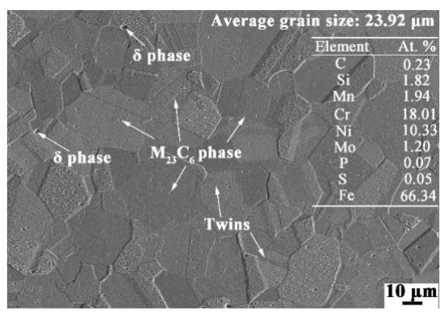
Figure 1. Schematic of the static corrosion experiment.
Crystals 15 00280 g001
Figure 2. Photos of 316L SS specimens after static corrosion for different periods: (a) 0 h, (b) 25 h, (c) 50 h, (d) 100 h, (e) 200 h, (f) 400 h.
Crystals 15 00280 g002
Figure 3. Annual CR values and weight loss of 316L stainless steel immersed within the molten NaCl-KCl salt under Ar flow at a temperature of 700 °C for various time durations.
Crystals 15 00280 g003
Figure 4. SEM image of 316L stainless steel before corrosion.
Crystals 15 00280 g004
Figure 5. The acquired surface SEM images of the 316L SS specimens immersed in molten NaCl-KCl salts at 700 °C for varying time durations: (a,b) 25 h, (c,d) 50 h, (e,f) 100 h, (g,h) 200 h, and (i,j) 400 h.
Crystals 15 00280 g005
Figure 6. Ellingham-Richardson diagram for reactions. (a) metal/carbide and (b) metal/oxide.
Crystals 15 00280 g006
Figure 7. Elemental mapping images of 316L SS specimens immersed in molten NaCl-KCl salts at 700 °C for different time durations: (a1a8) 25 h, (b1b8) 50 h, (c1c8) 100 h, (d1d8) 200 h, (e1e8) 400 h.
Crystals 15 00280 g007
Figure 8. XRD patterns of 316L SS alloys in tNaCl-KCl molten salt at a temperature of 700 °C for varying time durations.
Crystals 15 00280 g008
Figure 9. The obtained cross-sectional SEM images of the 316L SS specimens immersed in molten NaCl-KCl salt at a temperature equal to 700 °C for varying time durations: (a) 25 h, (b) 50 h, (c) 100 h, (d) 200 h, and (e) 400 h.
Crystals 15 00280 g009
Figure 10. Elemental distribution and EDS line scanning of the cross-section for the 316L SS specimen following corrosion within the NaCl-KCl molten salt at a temperature equal to 700 °C for 400 h: (a) secondary electron image, (b) Fe, (c) Cr, (d) Ni; inserts show Fe, Cr, and Ni line scanning.
Crystals 15 00280 g010
Figure 11. Variation in the concentration values of Cr and Fe within the molten NaCl-KCl salt with immersion time.
Crystals 15 00280 g011
Figure 12. Schematic diagram illustrating the mechanism of corrosion of 316L SS in molten NaCl-KCl salt.
Crystals 15 00280 g012
Table 1. Elemental distribution (wt.%) of the experimental 316L SS.
ElementCSiMnCrNiMoPSFe
Content (wt.%)0.030.921.9316.9112.080.040.03Bal.
Table 2. The obtained CR values for the 316 SS alloy in various chloride salts in an inert environment.
Molten Salts SystemTemperature (°C)Time (h)CR (μm/year)
NaCl-MgCl2700240205.36 [11]
NaCl-KCl-MgCl2700100
400
261 [23]
51.3 [38]
NaCl-KCl-ZnCl2500120
240
350
291 [17]
198 [17]
191 [17]
NaCl-KCl700100
400
83.61 (this work)
47.22 (this work)
Table 3. Chemical compositions of various regions in Figure 5 (at.%).
RegionsCSiMnCrNiMoFeO
Figure 5a15.700.360.328.709.061.2361.892.75
Figure 5c15.530.260.408.569.731.2462.321.96
Figure 5e19.241.040.106.0811.091.9252.128.42
Figure 5g27.451.190.245.8610.202.0544.238.79
Figure 5i13.721.650.085.6013.393.4858.643.44
A30.250.370.548.807.010.9649.212.86
B23.855.380.352.906.9916.3433.9610.24
C21.925.620.342.158.4514.8232.5314.18
D26.975.680.182.716.8516.2832.129.21
Table 4. The obtained values of G for the probable reactions occurring at 700 °C.
ReactionΔG (kJ/mol)
Fe + Cl2(g) = FeCl2−221.23
Cr + Cl2(g) = CrCl2−275.97
Ni + Cl2(g) = NiCl2−159.71
4Fe + 3O2(g) = 2Fe2O3−1131.89
4Cr + 3O2(g) = 2Cr2O3−1756.17
2Ni + O2(g) = 2NiO−301.81
Fe + 2HCl(g) = FeCl2 + H2(g)−19.9
Cr + 2HCl(g) = CrCl2 + H2(g)−74.6
Ni + 2HCl(g) = NiCl2 + H2(g)41.6
4FeCl2 + 3O2(g) = 2Fe2O3 + 4Cl2(g)−246.98
4CrCl2 + 3O2(g) = 2Cr2O3 + 4Cl2(g)−652.28
2NiCl2 + O2(g) = 2NiO + 2Cl2(g)17.61
Disclaimer/Publisher’s Note: The statements, opinions and data contained in all publications are solely those of the individual author(s) and contributor(s) and not of MDPI and/or the editor(s). MDPI and/or the editor(s) disclaim responsibility for any injury to people or property resulting from any ideas, methods, instructions or products referred to in the content.

