Abstract
This study examines the mechanical behavior and deformation mechanisms of hot-forged 304L stainless steel for cryogenic applications such as LNG storage and low-temperature structural systems. Tensile testing revealed a significant strength increase from 618 MPa at room temperature to 1432 MPa at cryogenic temperatures, with elongation decreasing from 83.7% to 23.3%. Charpy impact testing showed a 28% reduction in absorbed energy at cryogenic temperatures due to enhanced strain-induced martensitic transformation (SIMT). The observed mechanical responses are attributed to reduced stacking fault energy (SFE) at lower temperatures, which promotes SIMT, deformation twinning, and dislocation interactions, affecting material strength and toughness. SEM and EBSD analysis confirmed extensive martensitic transformation, increased deformation twinning, and reduced remaining austenite, indicating a γ → ε → α’ transformation pathway that governs strain hardening. The high strain rate during Charpy impact testing induced localized adiabatic heating, partially suppressing SIMT and modifying fracture behavior by enhancing localized plasticity. These findings emphasize the interplay between SFE, strain rate, and phase transformation in governing the cryogenic mechanical performance of 304L stainless steel.
1. Introduction
The increasing demand for cryogenic materials in industries such as liquefied natural gas (LNG) storage and transportation, as well as emerging hydrogen energy systems, necessitates the development of structural materials with superior mechanical performance at extremely low temperatures [1,2,3]. Among these materials, 304L austenitic stainless steel has been widely utilized due to its excellent mechanical properties, corrosion resistance, and adaptability to cryogenic environments [3,4,5,6]. It is a key material for cryogenic storage tanks, pipelines, and pressure vessels, where maintaining high strength, ductility, and fracture resistance under service conditions is critical.
Numerous studies have explored the cryogenic behavior of 304L stainless steel in various industrial applications. For instance, Mallick et al. [2] investigated the deformation behavior of 304L at 0 °C, emphasizing the role of strain-induced martensitic transformation (SIMT) on microstructural evolution and strength. Zheng et al. [3] conducted tensile and Charpy impact tests on coarse-grained 304 between 20 and 298 K, reporting stable ductile fracture and high strength at 20 K, indicating the alloy’s robustness at cryogenic temperatures. Momeni et al. [5] examined thermomechanical processing of 301, 304, and 304L stainless steels, and demonstrated how SIMT and reverse transformation during annealing refine grain size and enhance mechanical performance. Zhao et al. [6] applied electrochemical noise (EN) and scanning Kelvin probe (SKP) methods to monitor stress corrosion cracking (SCC) propagation in pre-fatigued 304, confirming the alloy’s environmental resistance under dynamic cryogenic conditions. These investigations validate the industrial relevance and performance capability of 304L in cryogenic settings, including LNG transport and storage systems. However, the literature also reveals unresolved challenges, such as reduced ductility, localized brittle fracture, and incomplete understanding of SIMT kinetics and phase stability at low temperatures. Particularly, the mechanical response of 304L under different thermomechanical loading modes, including tensile and impact conditions, remains insufficiently characterized across the full cryogenic temperature spectrum.
A defining characteristic of 304L stainless steel is its ability to undergo SIMT during plastic deformation, which significantly alters its mechanical behavior [4,7,8,9,10,11,12,13,14]. The transformation from the metastable austenite (γ) phase to martensite (α′) is influenced by several factors, including stacking fault energy (SFE), deformation mode, strain rate, and temperature. At cryogenic temperatures, reduced SFE promotes SIMT and deformation twinning, both of which contribute to strength enhancement and elevated strain hardening capacity [2,9,15,16,17,18]. Nevertheless, these microstructural transformations are frequently accompanied by embrittlement and loss of ductility, which must be carefully controlled in safety-critical applications.
Despite previous efforts, the combined influence of SFE, strain rate, deformation twinning, and SIMT on the fracture mechanisms of 304L stainless steel has not been comprehensively evaluated under both quasi-static and high-strain-rate cryogenic conditions. Mechanical testing techniques such as tensile and Charpy impact testing offer critical insight into strain hardening, energy absorption, and fracture toughness. These are complemented by advanced characterization tools, including electron backscatter diffraction (EBSD) and scanning electron microscopy (SEM), which enable in-depth assessment of phase transformation, dislocation activity, and twin formation. Therefore, this study aims to investigate the deformation behavior, microstructural evolution, and mechanical performance of hot-forged 304L stainless steel under room and cryogenic temperature conditions. Through the integration of mechanical tests and microstructural analyses, with a focus on strain rate sensitivity and temperature-dependent SFE, this work provides new insight into the fundamental mechanisms governing the performance of 304L stainless steel in cryogenic service. The results contribute to the understanding and optimization of 304L for long-term structural reliability in demanding cryogenic applications such as LNG and hydrogen storage systems.
2. Materials and Methods
2.1. Material and Chemical Composition
The chemical composition of the STS304L stainless steel used in this study was 0.025C-0.382Si-1.805Mn-0.0332P-0.0085S-0.441Cu-8.048Ni-18.091Cr-0.227Mo-0.0816N (in wt%). The STS304L was hot-forged into flanges in accordance with ASTM A182 specifications, with a final forging temperature maintained at 1200 °C. The forging process involved multiple stages of heating and deformation to ensure a uniform distribution of strain. Post-forging, the material underwent water quenching to achieve a homogeneous microstructure suitable for cryogenic applications.
2.2. Microstructural Characterization
The microstructure of STS304L was characterized using optical microscopy (OM), scanning electron microscopy (SEM), and electron backscatter diffraction (EBSD). Specimens were prepared by mechanical grinding with silicon carbide (SiC) paper, followed by polishing with 3 μm and 1 μm diamond paste. For enhanced resolution during EBSD analysis, additional polishing was performed using 1/4 μm diamond paste and colloidal silica. Etching for OM and SEM observations was conducted using a 1:3 mixture of HNO3 and HCl for 30 s. EBSD analyses were carried out using JEOL’s JXA-iHP200F(JEOL Ltd., Tokyo, Japan) equipment, with a step size of 0.7 μm to ensure high-resolution mapping of deformation zones.
2.3. Mechanical Properties Evaluation
2.3.1. Tensile Testing
Tensile tests were conducted at room temperature and cryogenic temperatures (−180 °C) using a 100 kN MTS E45 universal testing machine (MTS Systems Corporation, Eden Prairie, MN, USA) at a strain rate of 10−3/s. Room temperature specimens conformed to ASTM E8 subsize specifications, with a gauge length of 24 mm and a diameter of 6 mm. For cryogenic testing, specimens with a gauge length of 14 mm and a diameter of 3 mm were used. They were cooled to −180 °C using a liquid nitrogen chamber, and the yield strength was determined using the 0.2% offset method. The detailed experimental setup is illustrated in Figure 1. Elongation was measured using crosshead displacement. While this method has inherent limitations in accuracy, it was deemed sufficient for comparative analysis due to the consistent setup and specimen geometry across all conditions. Each tensile test condition was repeated three times, and the median values were used for analysis to ensure reliability and consistency.
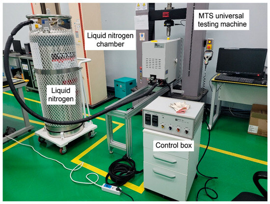
Figure 1.
Experimental setup for tensile testing at −180 °C under cryogenic conditions.
2.3.2. Charpy Impact Testing
Charpy impact tests were performed at room temperature and −196 °C using a Zwick/Roell PSW750(ZwickRoell GmbH & Co. KG, Ulm, Germany) impact testing machine equipped with a TZE instrumented module, with a maximum capacity of 750 J. The impact specimens were prepared in accordance with ASTM E23 standards [19] for Charpy V-notch (CVN) specimens. Each test was repeated three times to ensure statistical reliability, and the results were reported as the mean values along with standard deviations. Load–displacement curves were obtained using the TZE instrumented pendulum system integrated into the PSW750, which includes a high-speed force transducer and an angular encoder. The impact load was recorded by the striker-mounted force sensor, and the corresponding displacement was calculated from the pendulum swing angle. The signals were acquired in real-time and analyzed using TestXpert II (V3.61) software provided by Zwick/Roell. The absorbed energy was calculated from the area under the load–displacement curve to assess fracture toughness under different temperature conditions.
3. Results
3.1. Microstructure
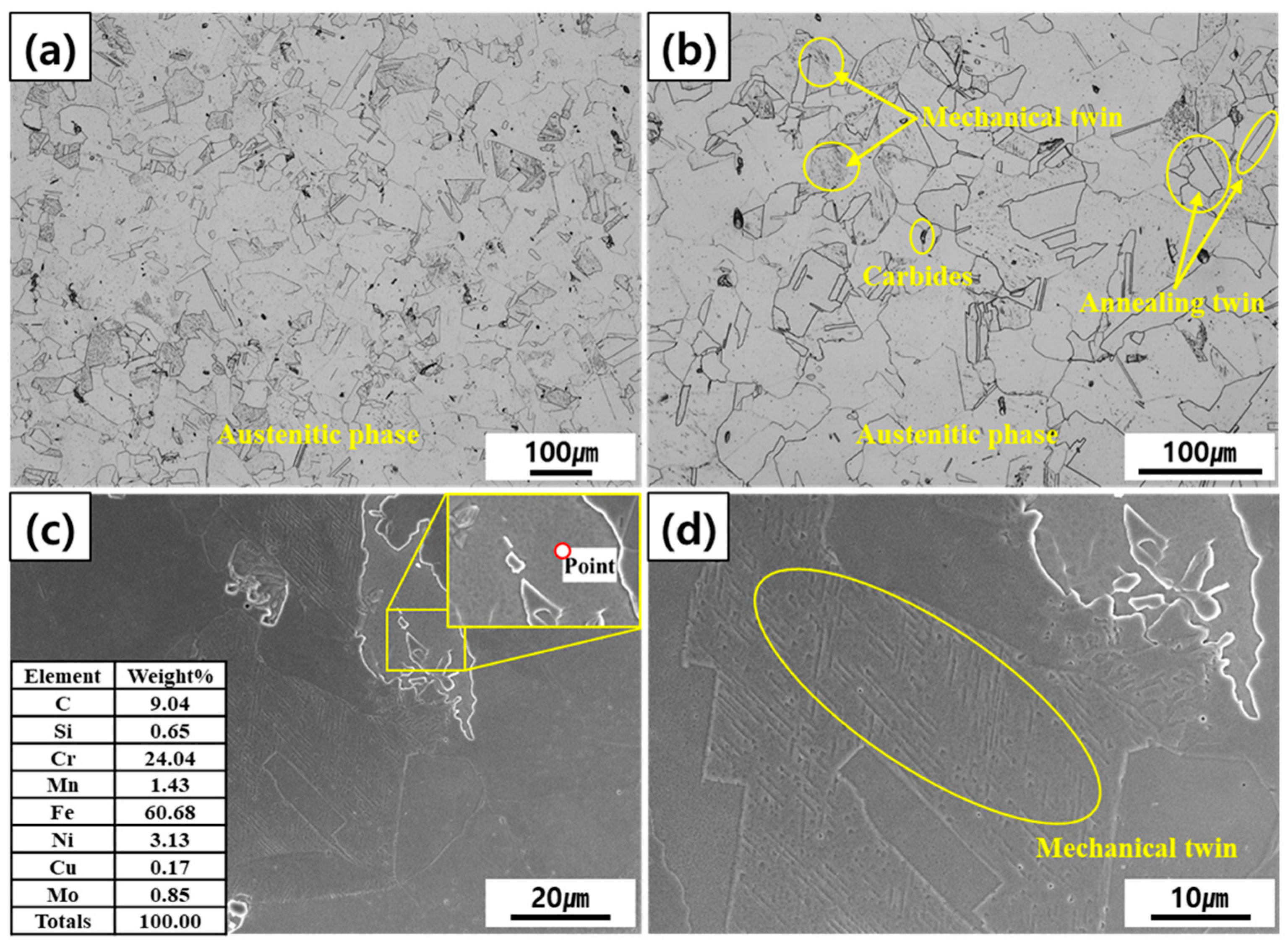
Figure 2 illustrates the microstructure of hot-forged STS304L stainless steel observed using optical microscopy (OM) and scanning electron microscopy (SEM). The optical micrographs in Figure 2a,b show that the microstructure is primarily composed of equiaxed austenitic grains, with an average grain size of approximately 91 μm. The grain boundaries are clearly defined, and both annealing twins and mechanical twins are observed in Figure 2b, which are characteristic features of austenitic stainless steels subjected to high-temperature forging [20]. Annealing twins form due to the low stacking fault energy (SFE) of austenitic stainless steel, which allows for twin boundary migration during the recrystallization process at elevated temperatures [21]. These twins contribute to grain refinement, enhancing mechanical properties such as strength and toughness. Due to the influence of the hot-forging process, the microstructure exhibits anisotropic characteristics, with localized deformation. A small amount of carbides was observed along some grain boundaries and within grains, as shown in Figure 2b, likely formed due to brief cooling delays or local thermal gradients during the forging and subsequent water-quenching process. These carbides may locally influence mechanical properties, particularly affecting strength and toughness. The SEM analysis in Figure 2c further confirms the general austenitic microstructure of STS304L and the presence of partial annealing twins, consistent with the OM results. To investigate the composition of the observed precipitates, an energy-dispersive X-ray spectroscopy (EDS) analysis was performed, revealing that the precipitates were Fe-Cr-based carbides, as shown in the marked region of Figure 2c. Figure 2d presents a magnified view of Figure 2c, clearly highlighting the formation of mechanical twins within the grain interior. Mechanical twinning occurs when the material is subjected to high-strain conditions, particularly at low temperatures or under dynamic loading. This deformation mechanism is activated when dislocation motion is restricted, causing the atomic planes to shift collectively along specific crystallographic orientations, forming twins. As shown in Figure 2d, these mechanical twins appear as fine, parallel lines within the austenitic grains. Mechanical twins enhance strain hardening and improve the material’s ability to withstand further deformation by providing additional barriers to dislocation motion. The formation of annealing twins is attributed to recrystallization during high-temperature forging, while mechanical twins result from significant plastic deformation under high-strain conditions. As the material has not undergone additional heat treatment after forging, the observed microstructural characteristics are primarily influenced by the hot-forging process. These microstructural features play a crucial role in determining the deformation behavior and mechanical properties of STS304L under various loading conditions. The presence of annealing twins contributes to improved ductility and strength by refining the grain structure, whereas mechanical twins enhance strain-hardening capacity, making the material more resistant to further deformation. Additionally, the Fe-Cr precipitates observed along grain boundaries and within grains may locally influence mechanical properties, affecting both toughness and hardness.
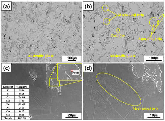
Figure 2.
Optical and SEM micrograph images of STS304L: (a) OM_×100, (b) OM_×200, (c) SEM_×1000, and (d) SEM_×2000.
3.2. Stacking Fault Energy Calculation
The phase transformation behavior of STS304L can be explained by the stacking fault energy (SFE), which decreases as the temperature decreases. SFE is influenced by both the elemental composition of the material and the ambient temperature. A lower SFE promotes deformation mechanisms that involve twinning and phase transformation rather than dislocation slip. As the temperature decreases, the SFE drops, enhancing the formation of martensite (α’) while suppressing epsilon (ε) martensite. This reduction in SFE at cryogenic temperatures facilitates the exclusive formation of martensite (α’), thereby stabilizing the martensitic phase and significantly influencing the material’s mechanical properties [2,8,22,23,24]. Figure 3 presents a graph illustrating the calculated SFE of STS304L based on its alloy composition. The values were calculated using Equations (1) and (2), which are based on the empirical formula proposed by P. Mallick [2], and plotted for the specific alloy composition of STS304L used in this study. In this study, the SFE was evaluated using the research findings of P. Mallick (2017) [2], and the calculation formula is provided as follows:
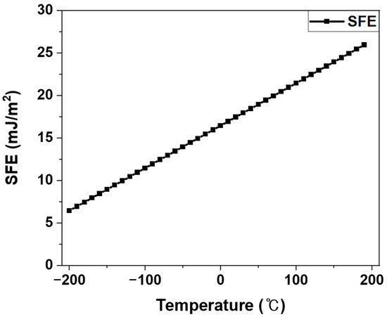
Figure 3.
Calculated stacking fault energy (SFE) of STS304L based on its alloy composition, using the empirical formula adapted from P. Mallick [2].
Using Equation (1), the SFE at room temperature (20 °C) is calculated to be approximately 17.4484 mJ/m2, which falls within the typical SFE range for STS304L (15–30 mJ/m2) [15,22]. Within this range, dislocation slip is the dominant deformation mechanism, although deformation twinning can also occur under high-strain conditions. However, according to Equation (2), at cryogenic temperatures (−196 °C), the SFE decreases sharply to 7.4484 mJ/m2, leading to significant changes in deformation behavior. A decrease in SFE alters the dominant deformation mechanism [2,8]. When the SFE is above 20 mJ/m2, dislocation slip primarily governs plastic deformation. As the SFE drops below 15 mJ/m2, deformation twinning becomes more active, competing with dislocation motion to accommodate plastic strain. When the SFE falls below approximately 10 mJ/m2, strain-induced martensitic transformation (SIMT) begins to dominate, as the nucleation and growth of martensite become energetically favorable [25]. At cryogenic temperatures, where the SFE is extremely low, nearly complete martensitic transformation occurs, contributing to a significant increase in strength but a reduction in ductility. Additionally, the suppression of epsilon (ε) martensite formation at low SFE values plays a critical role in determining the deformation characteristics. While ε-martensite can form as an intermediate phase in low-SFE FCC metals, STS304L primarily exhibits direct γ → α’ transformation at cryogenic temperatures due to its specific alloy composition and low SFE values. This transformation-driven deformation mechanism is responsible for the increased strength and reduced ductility observed at cryogenic temperatures. Understanding the correlation between SFE and deformation mechanisms provides critical insights into the mechanical behavior of STS304L under extreme conditions. These findings emphasize the necessity of microstructural control to optimize material performance for applications requiring high strength and toughness in cryogenic environments.
3.3. Tensile Test Result Analysis
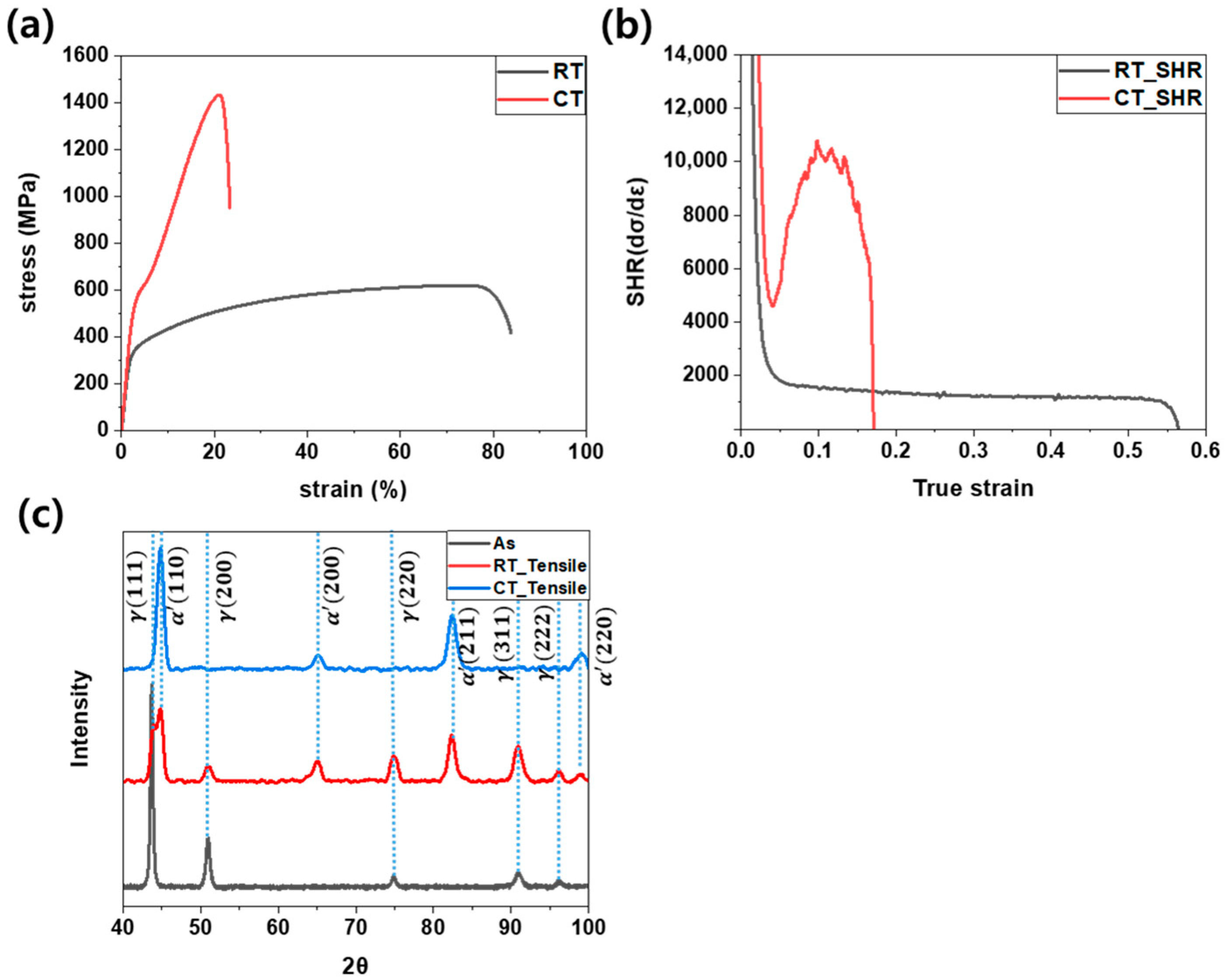
The tensile testing results of STS304L are presented to demonstrate its mechanical behavior under different temperature conditions. The stress–strain curves, shown in Figure 4a, highlight significant differences between room temperature and cryogenic environments. At room temperature, the tensile strength was approximately 618 MPa, the yield strength was 297 MPa, and the elongation was 83.7%. Under cryogenic conditions, the tensile strength increased significantly to 1432 MPa, while the yield strength rose to 478 MPa, and elongation decreased to 23.3%. This contrast reveals that cryogenic temperatures enhance the material’s strength but significantly reduce its ductility. These changes are attributed to factors such as crystal structure alterations, reduced dislocation activity, martensitic transformation, grain refinement, and residual stress [26,27]. Specifically, at cryogenic temperatures, the reduced activity of dislocations increases the material’s resistance to deformation, resulting in higher strength and lower elongation [17]. Figure 4b illustrates the strain hardening rate (SHR) curves of STS304L stainless steel at room temperature (RT) and cryogenic temperature (CT), highlighting the temperature-dependent deformation mechanisms [9,12,13,28]. The SHR behavior can be divided into three stages: (1) Dynamic Recovery, (2) Martensitic Transformation and Deformation Twinning, and (3) Saturation and Softening. In Stage 1, the SHR declines as plastic deformation initiates through dislocation motion. At RT, thermal energy facilitates dynamic recovery, resulting in a steeper decline, whereas, at CT, limited recovery leads to rapid dislocation accumulation, increasing resistance to deformation. In Stage 2, strain-induced martensitic transformation (SIMT) and deformation twinning become prominent at CT, stabilizing or slightly increasing the SHR by introducing new phase boundaries that hinder dislocation motion. In contrast, RT exhibits a gradual decline due to delayed martensitic transformation and minimal twinning. In Stage 3, the SHR decreases as hardening mechanisms become saturated. At CT, martensitic transformation slows down, and high dislocation density suppresses further strengthening, whereas, at RT, earlier dynamic recovery results in a more rapid decline. The SHR curves underscore the influence of temperature on deformation behavior. At RT, deformation is primarily governed by dislocation slip, leading to a continuous SHR decline. In contrast, CT enhances strain hardening due to increased contributions from martensitic transformation and deformation twinning. The differences in SHR behavior align with the stacking fault energy (SFE) trends in Figure 3, where lower SFE at CT promotes SIMT and twinning, sustaining a higher SHR compared to RT. The X-ray diffraction (XRD) results shown in Figure 4c provide key insights into the phase transformations of STS304L during tensile deformation and their relationship with stacking fault energy (SFE). Before deformation, the specimen consisted solely of the austenite (γ) phase. After tensile testing at room temperature, both austenite (γ) and martensite (α’) phases were observed, indicating the occurrence of stress-induced martensitic transformation (SIMT). However, under cryogenic conditions, the deformed specimen contained only the martensite (α’) phase, with no remaining austenite detected. This observation highlights the strong influence of temperature on phase transformation behavior [12,13,28,29,30]. These findings further support the correlation between SFE and phase transformation. At room temperature, the relatively higher SFE suppresses martensitic transformation, allowing both dislocation slip and deformation twinning to contribute to the material’s plasticity. Consequently, only partial martensitic transformation occurs during tensile deformation. In contrast, at cryogenic temperatures, the significantly lower SFE promotes extensive martensitic transformation, resulting in the complete conversion of austenite to martensite. This transformation effectively enhances strength while reducing ductility, which aligns with the observed mechanical property changes at low temperatures. The XRD results confirm that the reduction in SFE at cryogenic temperatures plays a critical role in shifting the dominant deformation mechanism from dislocation slip and twinning to martensitic transformation. As a result, the material exhibits increased strength but decreased ductility in extreme temperature environments. Therefore, understanding the influence of SFE on phase transformations and mechanical properties is essential for optimizing the performance of STS304L in applications requiring tailored strength and ductility under cryogenic conditions.
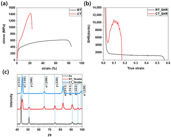
Figure 4.
Tensile properties of STS304L: (a) stress–strain curve, (b) strain hardening rate curve, and (c) XRD result of room temperature and cryogenic tensile specimen.
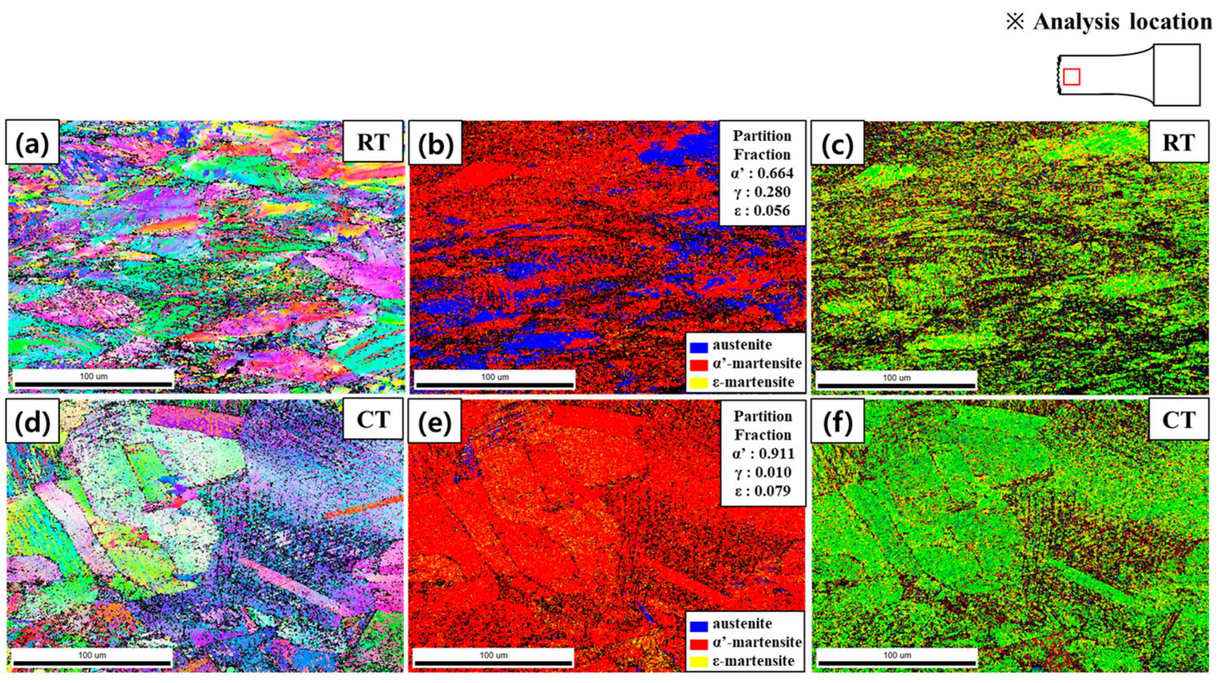
Figure 5 presents the results of electron backscatter diffraction (EBSD) analysis conducted on STS304L tensile specimens tested at room temperature (RT) and cryogenic temperature (CT), providing insights into microstructural evolution, deformation mechanisms, and phase transformation behavior under different temperature conditions. Figure 5a–c displays the Inverse Pole Figure (IPF), Phase, and Kernel Average Misorientation (KAM) maps for RT specimens. The IPF map in Figure 5a shows elongated grains along the tensile direction, indicative of significant plastic deformation. The Phase map in Figure 5b reveals a mixed-phase structure consisting of remaining austenite (γ), strain-induced martensite (α’), and a small fraction of ε-martensite (ε), highlighting the presence of the Transformation-Induced Plasticity (TRIP) effect. The relatively high stacking fault energy (SFE) (~17.4 mJ/m2) at RT favors dislocation slip as the dominant deformation mechanism, with the limited transformation of γ → α’ [7,9,31]. However, localized stress concentrations facilitate the formation of ε-martensite, which may act as an intermediate phase in the γ → ε → α’ transformation pathway [7,22]. The KAM map in Figure 5c highlights regions of high lattice distortion, confirming increased internal stresses due to dislocation activity and partial SIMT. In contrast, Figure 5d–f shows the EBSD results for CT specimens, where a more extensive phase transformation is observed. The IPF map in Figure 5d indicates severe lattice distortions and increased deformation twinning, a characteristic response to the significantly reduced SFE at low temperatures. The Phase map in Figure 5e reveals a drastic reduction in remaining austenite, with a substantial increase in both α’ and ε-martensite fractions. At CT, the lower SFE (~7.9 mJ/m2) promotes stacking fault formation, facilitating the γ → ε transformation more readily than at RT [2,8,14,23]. However, as deformation progresses, ε-martensite acts as a transient phase, further transforming into α’-martensite under continued strain. This sequential transformation mechanism (γ → ε → α’) plays a dominant role in the microstructural evolution at CT, contributing to the observed strengthening effects. The KAM map in Figure 5f further supports these findings, showing widespread high lattice distortions and internal stress concentrations, reflecting the dominant role of martensitic transformation in deformation at CT. The EBSD analysis underscores the temperature-dependent differences in deformation mechanisms and phase transformation behavior. At RT, plastic deformation is predominantly accommodated by dislocation slip, with partial SIMT and localized ε-martensite formation. In contrast, at CT, the reduced SFE facilitates both γ → ε and ε → α’ transformations, leading to an almost complete martensitic transformation. These phase transformation differences directly correlate with the mechanical properties observed in tensile tests, where higher SFE at RT allows for greater ductility, while lower SFE at CT results in increased strength but reduced plasticity. The lattice distortions and stress concentrations observed in the KAM maps further highlight the interplay between deformation mechanisms, phase transformations, and SFE, providing a direct link between microstructural evolution and mechanical performance.
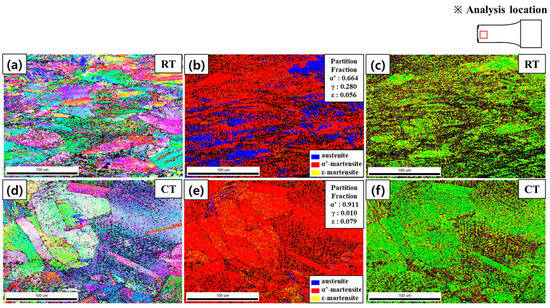
Figure 5.
STS304L Tensile test specimen EBSD mapping result: (a) RT_IPF map (b) RT_Phase map, (c) RT_KAM map, (d) CT_ IPF map, (e) CT_Phase map, and (f) CT_KAM map ※ Analysis location: The rectangular area in each map indicates the region selected for EBSD analysis.
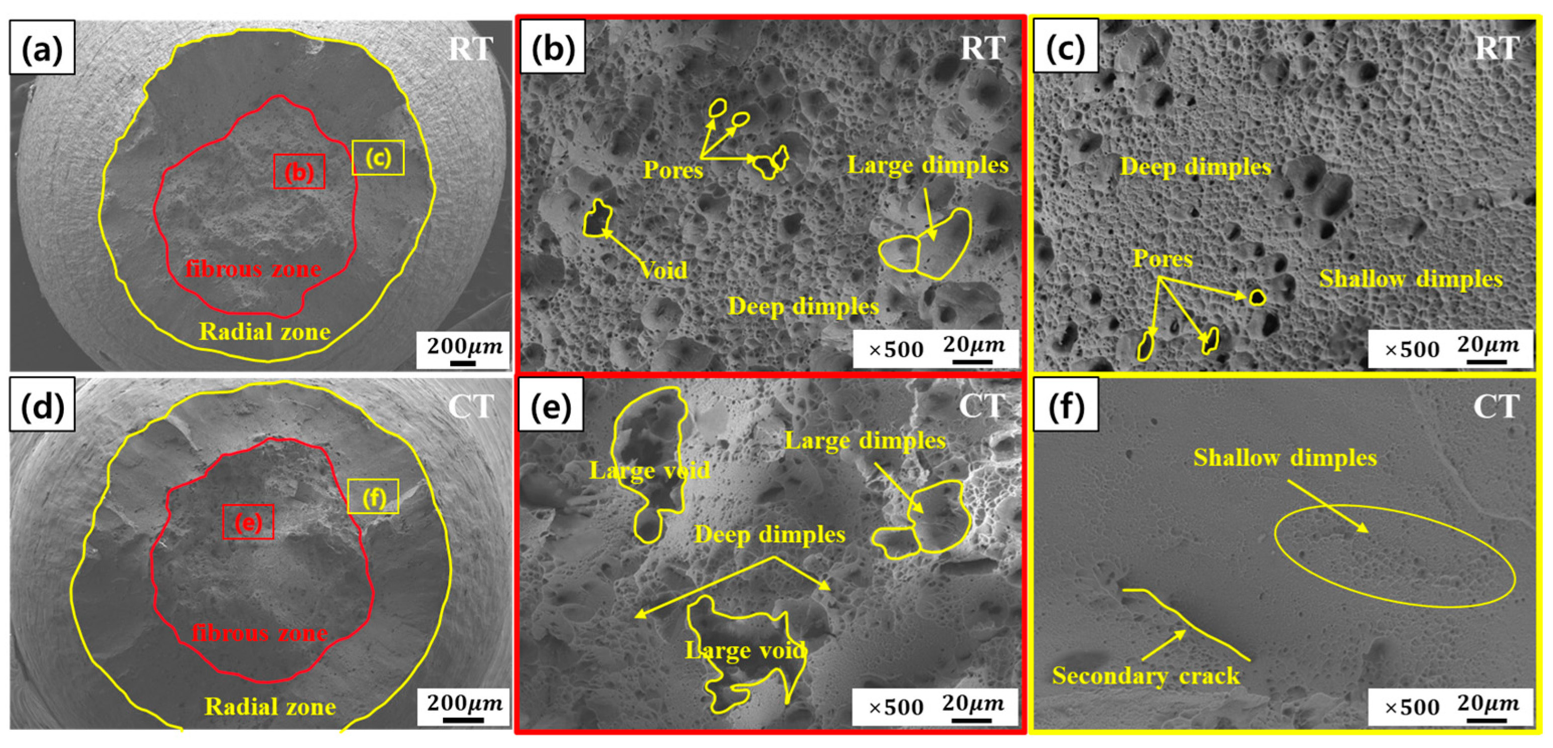
Figure 6 presents the fracture surface analysis of STS304L tensile specimens tested at room temperature (RT) and cryogenic temperature (CT), highlighting the temperature-dependent deformation and fracture mechanisms. The scanning electron microscopy (SEM) images reveal distinct variations in fracture morphology, attributable to the effects of strain-induced martensitic transformation (SIMT), dislocation motion, and stacking fault energy (SFE) [12,32]. At RT, as shown in Figure 6a–c, the fracture surface exhibits a ductile fracture mode characterized by a cup-and-cone morphology, extensive microvoid coalescence, and dimple formation. As shown in Figure 6b, the fibrous zone contains numerous dimples and pores, indicative of substantial plastic deformation facilitated by dislocation activity. Notably, large and deep dimples, accompanied by a variety of voids and pores, are evident in Figure 6b, further supporting the predominance of ductile failure. The radial zone, as depicted in Figure 6c, displays uniform dimple structures, reflecting homogeneous deformation. A closer inspection of Figure 6c reveals that regions near the center exhibit pores and deep dimples, while the outermost areas of the radial zone are dominated by shallow dimples, suggesting a spatial variation in plastic strain. At RT, the relatively high SFE (~17.4 mJ/m2) suppresses SIMT, thereby promoting dislocation glide as the dominant deformation mechanism. This results in high ductility (~83.7% elongation) and moderate tensile strength (~618 MPa). In contrast, fracture surfaces under CT conditions (Figure 6d–f) exhibit characteristics consistent with brittle fracture, primarily due to extensive SIMT. The macroscopic morphology shown in Figure 6d reveals a reduced fibrous zone and an enlarged radial zone, indicating a shift toward brittle behavior. As shown in Figure 6e, the dimple density is markedly reduced, and large voids are present, which reflects the limited plasticity associated with the near-complete transformation of austenite (γ) to martensite (α’) at a low SFE (~7.4 mJ/m2). In addition, Figure 6e reveals the presence of large and deep dimples alongside enlarged voids, indicating localized plastic deformation prior to fracture despite the overall brittle characteristics. The increased martensite volume fraction reduces dislocation mobility, leading to stress localization and accelerated crack propagation [33]. The radial zone in Figure 6f displays quasi-cleavage features, consistent with brittle fracture dominated by SIMT. Moreover, shallow dimples and secondary cracks are identified in the radial zone of Figure 6f, implying a mixed-mode fracture mechanism influenced by local stress concentration and limited ductility. The observed fracture morphologies are consistent with the tensile and microstructural results shown in Figure 3 and Figure 4. At RT, deformation is governed primarily by dislocation glide, resulting in ductile fracture. Conversely, at CT, the activation of SIMT leads to a significant increase in strength (~1432 MPa) but a substantial reduction in ductility (~23.3%), thereby promoting brittle fracture behavior. This temperature-dependent transition in fracture mode is attributed to the reduced SFE at CT, which enhances martensitic transformation and stacking fault formation, ultimately leading to a mixed-mode fracture mechanism.

Figure 6.
Tensile test specimen fracture surface of STS304L: (a) RT_macro (×30), (b) RT_center (×500), (c) RT_edge (×500), (d) CT_macro (×50), (e) CT_center (×500) and (f) CT_edge (×500). The red line in (a,d) indicates the fibrous zone, and the yellow line denotes the radial zone.
3.4. Charpy Impact Test Result Analysis
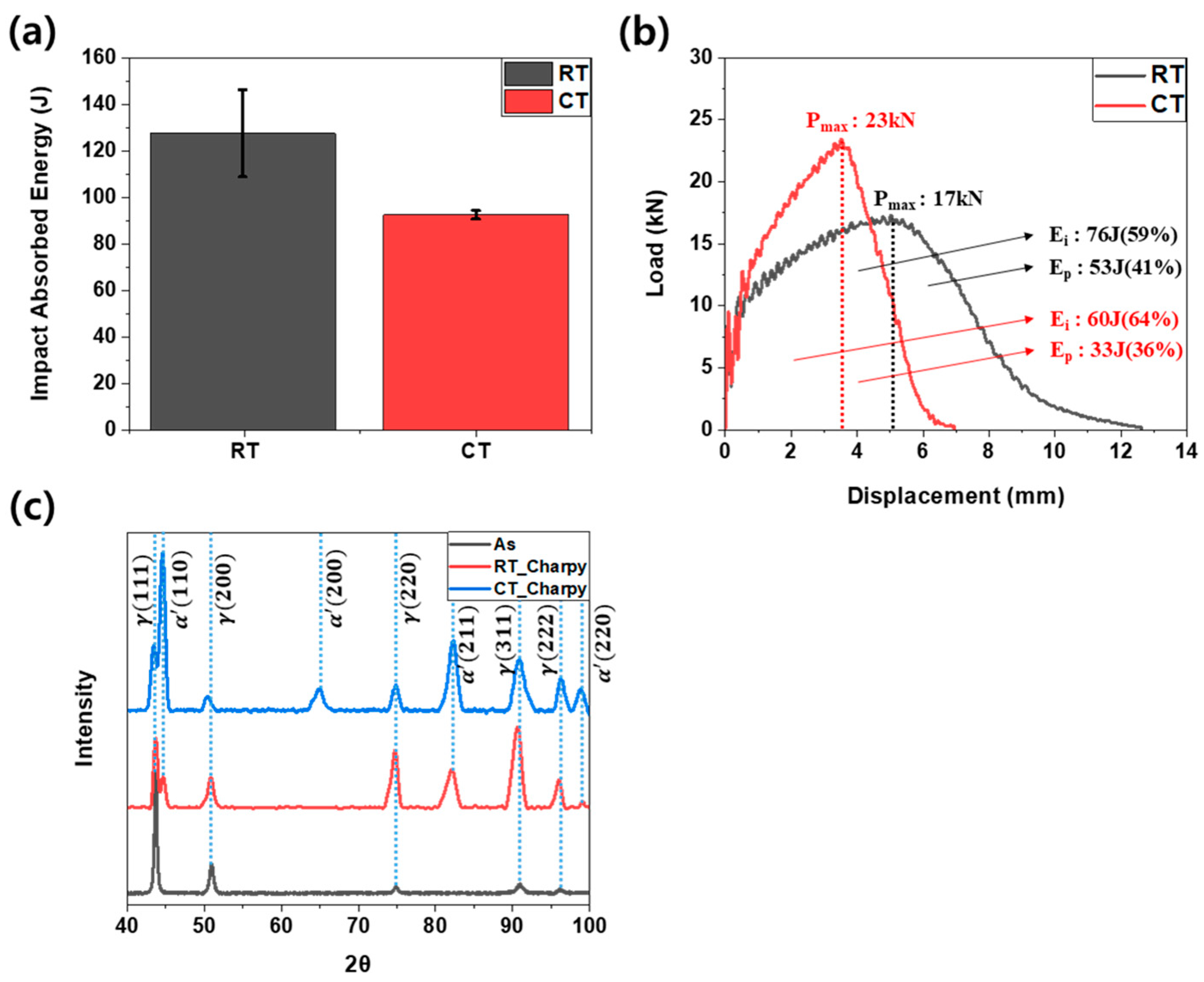
Figure 7 presents the Charpy impact test results, highlighting the differences in absorbed energy and fracture behavior at room and cryogenic temperatures, and their correlation with stacking fault energy (SFE) and strain-induced martensitic transformation (SIMT) [12,32]. Figure 7a shows the average absorbed energy, with the value at room temperature (RT) measured to be approximately 127 J. At cryogenic temperatures (CTs), the average absorbed energy decreases by approximately 28%, measuring around 92 J. This reduction indicates that the material becomes more brittle at lower temperatures, reflecting its diminished ability to absorb energy before fracture. This behavior is closely linked to the stacking fault energy (SFE) and its influence on phase transformation mechanisms. At RT, the relatively high SFE stabilizes the austenite phase (γ), suppressing extensive martensitic transformation, which allows plastic deformation via dislocation motion to be the dominant energy dissipation mechanism. In contrast, at CT, the significantly reduced SFE facilitates stacking fault formation, which acts as a precursor to strain-induced martensitic transformation (γ → α’). As a result, a larger fraction of austenite transforms into martensite, increasing material strength and stiffness while reducing plastic deformation capacity, thereby leading to a lower amount of absorbed energy [16,34,35]. Figure 7b illustrates the load–displacement curves obtained from the Charpy impact tests. Key parameters, including crack initiation energy (Ei) and crack propagation energy (Ep), were calculated as the areas under the load–displacement curves relative to the maximum load (Pmax). The maximum load (Pmax) increased from 17 kN at RT to 23 kN at CT, which can be attributed to the increased material stiffness and suppressed thermal activity at lower temperatures. As SFE decreases at CT, SIMT is significantly enhanced, leading to a higher fraction of martensite formation, which increases resistance to crack propagation and enhances stiffness [17]. Additionally, the crack initiation energy (Ei) increased from approximately 58% at RT to about 64% at CT, indicating that a greater proportion of the absorbed energy is consumed during the crack initiation phase under cryogenic conditions. This is a direct consequence of the increased martensite content at CT, which strengthens the material and increases crack initiation resistance. However, while martensitic transformation increases strength and toughness locally, it also reduces the overall plasticity of the material, limiting its energy dissipation capacity, as reflected in the lower total absorbed energy [36]. The deformation mechanisms during the Charpy impact tests reveal that, at RT, energy dissipation is primarily dominated by plastic deformation via dislocation motion, while, at CT, the reduction in SFE significantly alters the fracture behavior by enhancing strain-induced martensitic transformation [37,38]. This trend is further supported by X-ray diffraction (XRD) analysis, as shown in Figure 7c. After Charpy impact testing, both austenite (γ) and martensite (α’) phases were detected at both temperature conditions. However, the intensity of the martensite peak was significantly higher at CT, confirming the dominant role of SIMT in the material’s fracture behavior at low temperatures. At RT, the relatively high SFE allows deformation to be primarily accommodated by dislocation motion and plastic deformation, resulting in limited martensite formation. In contrast, at CT, the lower SFE promotes the nucleation of stacking faults, which serve as precursors for strain-induced martensitic transformation (γ → α’). This transformation increases the material’s strength and stiffness while reducing its ability to undergo extensive plastic deformation, leading to the observed decrease in absorbed energy. These results emphasize the critical role of SFE and SIMT in governing the mechanical behavior of STS304L at cryogenic temperatures. The enhanced martensite formation at low temperatures significantly increases crack initiation energy and stiffness but reduces plastic deformation capacity and overall absorbed energy. The interplay between SIMT, TRIP, and SFE highlights the importance of considering temperature-dependent phase transformations when designing and applying STS304L in cryogenic environments, where maintaining a balance between strength and energy absorption is crucial.

Figure 7.
Charpy impact properties of STS304L: (a) Charpy absorbed energy, (b) load–displacement curves, and (c) XRD graph of room temperature and cryogenic Charpy impact test specimen.
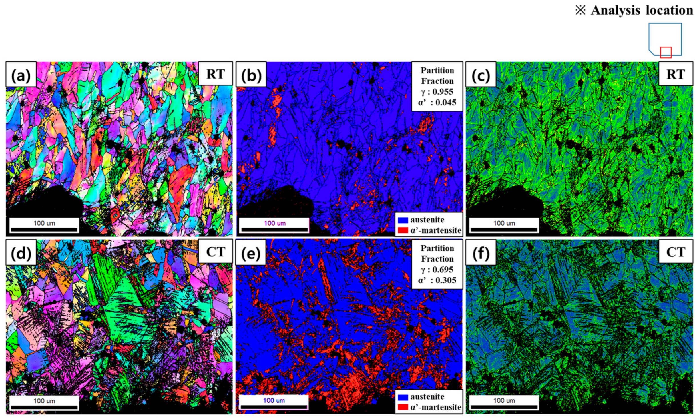
Figure 8 illustrates the microstructural evolution of STS304L after Charpy impact testing at room temperature (RT) and cryogenic temperature (CT), as analyzed through electron backscatter diffraction (EBSD). These results provide insights into the deformation mechanisms, phase transformation behavior, and their correlation with stacking fault energy (SFE) and fracture characteristics. Figure 8a–c shows the EBSD results for RT specimens. The IPF map (Figure 8a) reveals elongated grains aligned with the loading direction, indicative of significant plastic deformation dominated by dislocation motion. The Phase map (Figure 8b) shows partial strain-induced martensitic transformation (SIMT), where only localized regions experience γ → α’ transformation due to high stress concentrations. The KAM map (Figure 8c) highlights regions of high lattice misorientation, suggesting dislocation accumulation and twin formation, which contribute to energy dissipation and ductile fracture behavior. At RT, the relatively high SFE stabilizes austenite, allowing plastic deformation via dislocation slip and TRIP-assisted twinning, resulting in higher absorbed energy (~127 J). Figure 8d–f displays the EBSD results for CT specimens, where deformation mechanisms shift due to the reduced SFE. The IPF map (Figure 8d) reveals deformation bands and strain localization, indicating the activation of deformation twinning and extensive SIMT. The Phase map (Figure 8e) confirms a significant increase in martensite fraction, with austenite content dropping from ~0.805 at RT to ~0.554 at CT. This transformation is driven by stacking fault formation, which promotes γ → α’ nucleation, increasing strength and reducing ductility. The KAM map (Figure 8f) further supports these findings, showing higher misorientation within martensitic regions and along grain boundaries, where strain accumulation leads to embrittlement. During Charpy impact testing, adiabatic heating due to rapid deformation temporarily raises the local temperature, which can influence martensitic transformation [39,40]. At CT, this localized heating slightly delays SIMT, allowing limited plasticity before full transformation occurs. However, the overall lower SFE still favors rapid martensitic nucleation, leading to increased strength but reduced ductility (~92 J absorbed energy). This contrasts with RT conditions, where dislocation motion dominates, permitting greater energy dissipation before fracture. In conclusion, EBSD analysis confirms that temperature-dependent deformation mechanisms significantly affect STS304L’s impact performance. At RT, higher SFE stabilizes austenite, allowing TRIP-driven plastic deformation and higher energy absorption. At CT, reduced SFE enhances SIMT and twinning, increasing strength but limiting plasticity. The influence of adiabatic heating during Charpy impact further modifies transformation kinetics, slightly delaying SIMT but not preventing brittle fracture. These findings provide a direct correlation between SFE, phase transformation, and mechanical behavior, offering insights for optimizing STS304L’s performance in cryogenic applications.
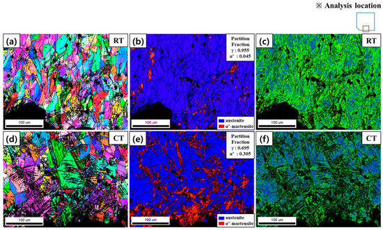
Figure 8.
STS304L Charpy impact test specimen EBSD mapping result: (a) RT_IPF map (b) RT_Phase map, (c) RT_KAM map, (d) CT_ IPF map, (e) CT_Phase map and (f) CT_KAM map. ※ Analysis location: The rectangular area in each map indicates the region selected for EBSD analysis.
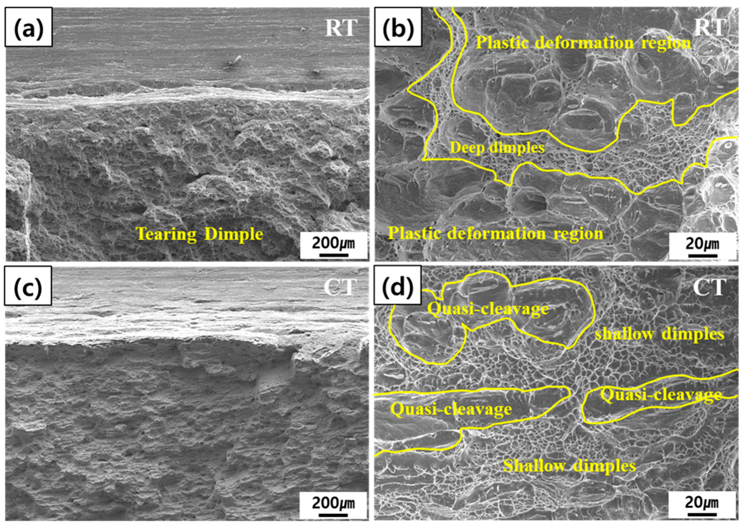
Figure 9 presents SEM images of the fracture surfaces of Charpy impact specimens of STS304L, highlighting the temperature-dependent fracture mechanisms and their correlation with mechanical properties. At room temperature (RT), ductile dimples were predominantly observed, while, at cryogenic temperature (CT), the fracture surfaces exhibited both dimples and quasi-cleavage patterns, indicating a mixed-mode failure. These features reflect the interplay between dislocation motion and strain-induced martensitic transformation (SIMT) during impact loading [41]. At room temperature (RT), as shown in Figure 9a,b, the fracture surface features large and deep dimples, indicative of significant plastic deformation. In particular, Figure 9a exhibits widespread tearing dimples across the fracture surface, characteristic of ductile tearing under high energy absorption. The high stacking fault energy (SFE) (~17.4 mJ/m2) suppresses extensive martensitic transformation, allowing dislocation motion and transformation-induced plasticity (TRIP) to dominate deformation. Moreover, Figure 9b reveals deep dimples accompanied by plastically deformed regions, likely induced by external stress during impact, suggesting localized plastic flow. This results in a ductile fracture mode with microvoid coalescence as the primary failure mechanism, promoting high energy absorption. In contrast, at cryogenic temperature (CT), as seen in Figure 9c,d, the fracture surface exhibits smaller and shallower dimples alongside prominent quasi-cleavage features, indicating a transition to brittle behavior. The reduced SFE (~7.4 mJ/m2) promotes stacking fault formation, accelerating SIMT (γ → α’) and increasing material strength and stiffness while limiting plastic deformation. Specifically, Figure 9d shows shallow dimples coexisting with quasi-cleavage facets, indicating a reduction in ductility and the presence of localized brittle zones. The extended deformation zone near the notch at CT reflects increased crack initiation resistance, but reduced ductility leads to brittle fracture characteristics. These fracture observations align with the mechanical data, where RT specimens exhibit high ductility and impact energy absorption, while CT specimens show increased strength but reduced plasticity due to enhanced martensitic transformation. The shift from dislocation-dominated deformation at RT to martensite-dominated strengthening at CT highlights the critical role of SFE in governing impact fracture behavior. In conclusion, at RT, TRIP facilitates extensive plasticity, leading to ductile fracture, whereas, at CT, SIMT dominates, promoting localized stress concentrations and brittle failure. These findings emphasize the importance of controlling SFE for optimizing fracture toughness and impact resistance in extreme temperature environments.

Figure 9.
Charpy impact test specimen fracture surface of STS304L: (a) RT_notch (×50), (b) RT (×500), (c) CT_notch (×50) and (d) CT (×500).
3.5. Phase Transformation and Quantitative Analysis
Figure 10 presents the quantitative EBSD results showing the phase fractions of austenite (γ), α’-martensite, and ε-martensite in STS304L, which illustrate the temperature- and strain-rate-dependent martensitic transformation behavior under tensile and Charpy impact testing. The transformation from γ to α’ is governed by stacking fault energy (SFE), strain rate, and temperature, all of which significantly influence the deformation mechanisms and mechanical properties of the material [2,9,15,16,17,18]. Under tensile loading at room temperature (RT), a notable transformation occurs with the austenite fraction decreasing to 28.0%, α’-martensite increasing to 66.4%, and ε-martensite forming at 5.6%. The relatively higher SFE at RT allows deformation to proceed primarily through dislocation motion, with SIMT occurring progressively as strain accumulates. The presence of ε-martensite suggests a γ → ε → α’ transformation path, particularly in localized high-strain regions. At cryogenic temperature (CT), this transformation is markedly enhanced due to the further reduction in SFE. EBSD analysis shows that remaining austenite decreases sharply to 1.0%, while α’-martensite increases to 91.1%. ε-martensite also increases to 7.9%, suggesting it acts as an intermediate product during the transformation, facilitated by increased stacking fault formation due to lower thermal activation [42]. In contrast, under high strain-rate Charpy impact testing, the transformation behavior differs. At RT, the remaining austenite remains high at 95.5%, with only 4.5% α’-martensite, indicating that high strain rates suppress SIMT and deformation proceeds mainly via dislocation motion and twinning. At CT, the austenite fraction decreases to 69.5% and α’-martensite increases to 30.5%. Although transformation is more pronounced than at RT, it remains lower than in tensile tests due to adiabatic heating during impact loading, which locally elevates the temperature and delays martensite nucleation [39,40]. Comparing the tensile and Charpy tests, the tensile loading condition enables more uniform and progressive SIMT, yielding a higher α’-martensite content. In contrast, the high strain rate in impact testing limits both the nucleation and growth of martensite, resulting in higher remaining austenite. These findings are consistent with prior observations of stress–strain behavior, fracture surface morphology, and XRD results presented earlier. The presence of ε-martensite, particularly in tensile specimens tested at CT, supports a sequential γ → ε → α’ transformation route, while the more direct γ → α’ path dominates under impact conditions where ε formation is suppressed. Overall, the EBSD analysis reinforces the idea that the extent and pathway of martensitic transformation in STS304L are governed primarily by temperature, strain rate, and deformation mode. The enhanced transformation at CT underscores the importance of SFE in controlling phase stability and mechanical performance. These results are fully consistent with microstructural and mechanical findings presented across the tensile and impact testing observations.
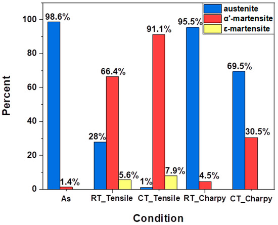
Figure 10.
Quantitative EBSD results showing austenite and martensite (α’ and ε) fractions of STS304L.
3.6. Effect of Temperature and Strain Rate on SFE and Deformation Mechanism
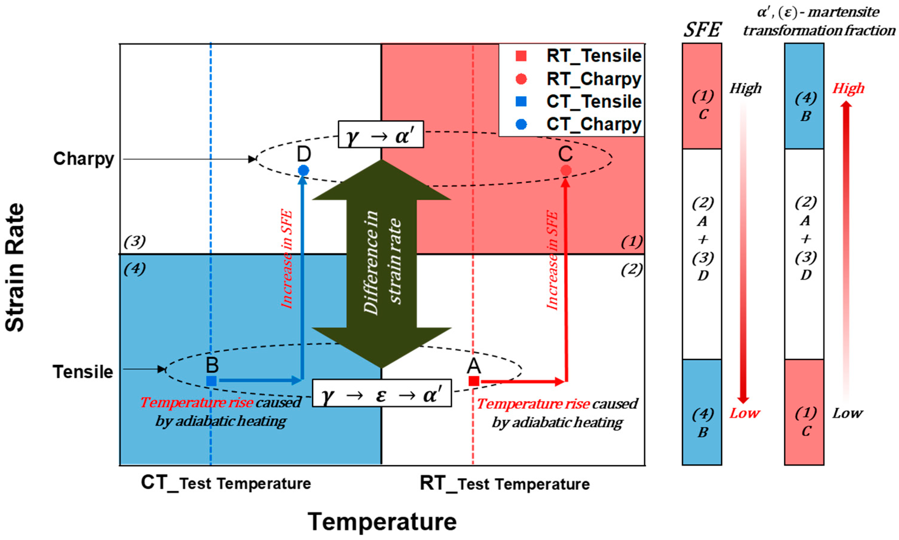
Figure 11 illustrates the combined effects of temperature, strain rate, and stacking fault energy (SFE) on deformation mechanisms and strain-induced martensitic transformation (SIMT) in STS304L stainless steel. The observed phase transformation behaviors and mechanical responses across different testing conditions are directly linked to variations in SFE, which governs the activity of dislocation slip, deformation twinning, and martensitic nucleation [2,9,15,16,17,18]. In tensile tests (Points A and B), the strain rate is relatively low, allowing sufficient time for thermally activated SIMT to progress. At room temperature (Point A), the SFE remains relatively high, favoring dislocation motion as the dominant deformation mechanism and partially suppressing twinning and martensitic transformation [7,9,31]. Conversely, at cryogenic temperatures (Point B), reduced SFE promotes deformation twinning and facilitates the transformation from γ to α’-martensite, increasing work hardening but reducing ductility [2,8,22,23,24]. The sequential transformation path γ → ε → α’ is more evident in this condition, as supported by XRD and EBSD analyses (Figure 10). In Charpy impact tests (Points C and D), the high strain rates lead to localized adiabatic heating, which elevates the local specimen temperature and transiently increases SFE. This effect can delay or suppress the full progression of SIMT [39,40], even though rapid deformation favors the nucleation of martensite. At room temperature (Point C), the high strain rate and elevated SFE result in minimal martensitic transformation. At cryogenic temperature (Point D), although martensite formation is more pronounced than at Point C, it remains lower than in cryogenic tensile tests due to the competing effects of high strain rate and adiabatic heating. The correlation shown in Figure 11 confirms that impact tests generally result in higher effective SFE compared to tensile tests at equivalent temperatures, owing to dynamic thermal effects. The hierarchy of SFE inferred from the analysis—lowest at B (cryogenic tensile), followed by A and D (room temperature tensile and cryogenic impact), and highest at C (room temperature impact)—aligns with the observed transformation extents. Interestingly, although both specimens A and D are tested under similar temperatures, specimen A exhibits a greater degree of martensitic transformation. This is attributed to the longer deformation time and absence of adiabatic heating during tensile loading, emphasizing the dominant role of strain rate in governing transformation kinetics. These findings reinforce the idea that SFE alone does not fully dictate the transformation pathway. Instead, the combined effects of temperature, strain rate, and deformation mode determine the progression of SIMT and the associated phase stability. Under low-strain-rate conditions, the transformation follows the γ → ε → α’ route, while at higher strain rates, the limited time for intermediate ε-martensite formation promotes a more direct γ → α’ path [7,22]. The interplay of these variables directly influences the plasticity, strain-hardening response, and fracture behavior of STS304L under extreme service conditions.

Figure 11.
Effect of temperature and strain rate on SFE and deformation mechanisms in STS304L stainless steel.
4. Conclusions
This study systematically investigated the temperature-dependent deformation and fracture mechanisms of hot-forged 304L stainless steel under conditions relevant to cryogenic applications, such as LNG storage and low-temperature structural systems. Tensile testing demonstrated that cryogenic temperatures significantly enhanced the material’s strength while reducing its ductility, primarily due to strain-induced martensitic transformation (SIMT). This transformation is facilitated by a decrease in stacking fault energy (SFE) at lower temperatures, promoting the nucleation of deformation twins and martensitic phases. Strain hardening rate (SHR) analysis revealed distinct three-stage hardening behavior at cryogenic conditions, highlighting the critical role of SIMT and twinning in strain accommodation and strength enhancement. In contrast, room-temperature deformation exhibited a more uniform and gradual strain hardening response due to less pronounced martensitic transformation. X-ray diffraction (XRD) confirmed a complete transformation from the austenite (γ) phase to α’-martensite under cryogenic conditions, whereas room-temperature deformation resulted in a partial transformation. SEM fracture surface analysis further indicated a shift from ductile fracture mechanisms, characterized by cup-and-cone shapes and dimples at room temperature, to brittle fracture features, including quasi-cleavage facets and larger voids at cryogenic temperatures. These findings underscore the embrittlement associated with enhanced SIMT. Charpy impact testing showed a notable decrease in absorbed energy at cryogenic temperatures. The increased maximum load and crack initiation energy at these temperatures suggest heightened resistance to crack initiation, although overall energy absorption decreased due to enhanced brittleness. EBSD analysis identified a pronounced increase in deformation twinning and martensitic phase fraction at cryogenic conditions. The observed presence of ε-martensite indicates a sequential γ → ε → α’ transformation mechanism during tensile deformation. However, the rapid strain rates and resultant adiabatic heating during Charpy impact testing suppressed ε-phase formation, leading to a direct γ → α’ transformation pathway. Therefore, the interplay of temperature-dependent SFE, deformation twinning, and strain rate-driven phase transformation pathways is critical in controlling the mechanical performance of STS304L stainless steel. Optimizing these factors is essential to ensure the structural reliability and long-term performance of materials in extreme cryogenic environments.
Author Contributions
Data curation, J.-B.J.; formal analysis, C.L.; investigation, G.-H.L.; methodology, B.K. and J.-B.J.; project administration, S.N.; resources, G.J.; software, C.L.; supervision, B.J.K.; validation, C.C. and H.-S.P.; visualization, S.N.; writing—original draft, G.-H.L. and B.J.K.; writing—review and editing, B.K. and S.N. All authors have read and agreed to the published version of the manuscript.
Funding
This research was funded by the Ministry of SMEs and Startups (MSS), Republic of Korea, under the R&D Program of the Small and Medium Enterprise (SME) Technology Innovation Development Project, grant number 00509252.
Data Availability Statement
Data are contained within the article.
Acknowledgments
The authors would like to acknowledge the support provided by the SME Technology Innovation Development Project titled “Development of High-Performance Precipitation-Hardened Stainless Steels and Forging Technology for Eco-Friendly Compressors”.
Conflicts of Interest
Authors Changyong Choi and Hee-Sang Park are employed by the Felix Technology Co., Ltd. The remaining authors declare that the research was conducted in the absence of any commercial or financial relationships that could be construed as a potential conflict of interest.
References
- Balat, M. Potential importance of hydrogen as a future solution to environmental and transportation problems. Int. J. Hydrogen Energy 2008, 33, 4013–4029. [Google Scholar] [CrossRef]
- Mallick, P.; Tewary, N.; Ghosh, S.; Chattopadhyay, P. Effect of cryogenic deformation on microstructure and mechanical properties of 304 austenitic stainless steel. Mater. Charact. 2017, 133, 77–86. [Google Scholar] [CrossRef]
- Zheng, C.; Yu, W. Effect of low-temperature on mechanical behavior for an AISI 304 austenitic stainless steel. Mater. Sci. Eng. A 2018, 710, 359–365. [Google Scholar] [CrossRef]
- Gupta, A.K.; Krishnamurthy, H.N.; Singh, Y.; Prasad, K.M.; Singh, S.K. Development of constitutive models for dynamic strain aging regime in Austenitic stainless steel 304. Mater. Des. 2013, 45, 616–627. [Google Scholar] [CrossRef]
- Momeni, A.; Abbasi, S. Repetitive thermomechanical processing towards ultra fine grain structure in 301, 304 and 304L stainless steels. J. Mater. Sci. Technol. 2011, 27, 338–343. [Google Scholar] [CrossRef]
- Zhao, R.; Zhang, Z.; Shi, J.-b.; Tao, L.; Song, S.-z. Characterization of stress corrosion crack growth of 304 stainless steel by electrochemical noise and scanning Kelvin probe. J. Cent. South Univ. Technol. 2010, 17, 13–18. [Google Scholar] [CrossRef]
- Linderov, M.; Segel, C.; Weidner, A.; Biermann, H.; Vinogradov, A. Deformation mechanisms in austenitic TRIP/TWIP steels at room and elevated temperature investigated by acoustic emission and scanning electron microscopy. Mater. Sci. Eng. A 2014, 597, 183–193. [Google Scholar] [CrossRef]
- Dumay, A.; Chateau, J.-P.; Allain, S.; Migot, S.; Bouaziz, O. Influence of addition elements on the stacking-fault energy and mechanical properties of an austenitic Fe–Mn–C steel. Mater. Sci. Eng. A 2008, 483, 184–187. [Google Scholar] [CrossRef]
- Byun, T.; Hashimoto, N.; Farrell, K. Temperature dependence of strain hardening and plastic instability behaviors in austenitic stainless steels. Acta Mater. 2004, 52, 3889–3899. [Google Scholar] [CrossRef]
- Hokka, M.; Kuokkala, V.-T.; Curtze, S.; Vuoristo, T.; Apostol, M. Characterization of strain rate and temperature dependent mechanical behavior of TWIP steels. J. Phys. IV 2006, 134, 1301–1306. [Google Scholar] [CrossRef]
- Cios, G.; Tokarski, T.; Żywczak, A.; Dziurka, R.; Stępień, M.; Gondek, Ł.; Marciszko, M.; Pawłowski, B.; Wieczerzak, K.; Bała, P. The investigation of strain-induced martensite reverse transformation in AISI 304 austenitic stainless steel. Metall. Mater. Trans. A 2017, 48, 4999–5008. [Google Scholar] [CrossRef]
- Soares, G.C.; Rodrigues, M.C.M.; Santos, L.d.A. Influence of temperature on mechanical properties, fracture morphology and strain hardening behavior of a 304 stainless steel. Mater. Res. 2017, 20, 141–151. [Google Scholar] [CrossRef]
- Qin, Z.; Xia, Y. Role of strain-induced martensitic phase transformation in mechanical response of 304L steel at different strain-rates and temperatures. J. Mater. Process. Technol. 2020, 280, 116613. [Google Scholar] [CrossRef]
- Sunil, S.; Kapoor, R. Effect of strain rate on the formation of strain-induced martensite in AISI 304L stainless steel. Metall. Mater. Trans. A 2020, 51, 5667–5676. [Google Scholar] [CrossRef]
- Schramm, R.; Reed, R. Stacking fault energies of seven commercial austenitic stainless steels. Metall. Trans. A 1975, 6, 1345–1351. [Google Scholar] [CrossRef]
- Park, J.; Lee, K.; Sung, H.; Kim, Y.J.; Kim, S.K.; Kim, S. J-integral fracture toughness of high-Mn steels at room and cryogenic temperatures. Metall. Mater. Trans. A 2019, 50, 2678–2689. [Google Scholar] [CrossRef]
- Odnobokova, M.; Belyakov, A.; Enikeev, N.; Kaibyshev, R.; Valiev, R. Cryogenic impact toughness of a work hardened austenitic stainless steel. Materialia 2022, 23, 101460. [Google Scholar] [CrossRef]
- Liu, J. Deformation Induced Martensitic Transformation in 304 Stainless Steels; University of South Carolina: Columbia, SC, USA, 2016. [Google Scholar]
- ASTM E23-18; Standard Test Methods for Notched Bar Impact Testing of Metallic Materials. ASTM International Publish: West Conshohocken, PA, USA, 2018.
- Guo, Y.; Han, E.-H.; Wang, J. Effects of forging and heat treatments on the microstructure and oxidation behavior of 316LN stainless steel in high temperature water. J. Mater. Sci. Technol. 2015, 31, 403–412. [Google Scholar] [CrossRef]
- Randle, V. Mechanism of twinning-induced grain boundary engineering in low stacking-fault energy materials. Acta Mater. 1999, 47, 4187–4196. [Google Scholar] [CrossRef]
- Galindo-Nava, E.; Rivera-Díaz-del-Castillo, P. Understanding martensite and twin formation in austenitic steels: A model describing TRIP and TWIP effects. Acta Mater. 2017, 128, 120–134. [Google Scholar] [CrossRef]
- Allain, S.; Chateau, J.-P.; Bouaziz, O. A physical model of the twinning-induced plasticity effect in a high manganese austenitic steel. Mater. Sci. Eng. A 2004, 387, 143–147. [Google Scholar] [CrossRef]
- Curtze, S.; Kuokkala, V.-T. Dependence of tensile deformation behavior of TWIP steels on stacking fault energy, temperature and strain rate. Acta Mater. 2010, 58, 5129–5141. [Google Scholar] [CrossRef]
- Shterner, V.; Timokhina, I.B.; Beladi, H. On the work-hardening behaviour of a high manganese TWIP steel at different deformation temperatures. Mater. Sci. Eng. A 2016, 669, 437–446. [Google Scholar] [CrossRef]
- Maloy, S.; James, M.; Willcutt, G.; Sommer, W.; Sokolov, M.; Snead, L.; Hamilton, M.; Garner, F. The mechanical properties of 316L/304L stainless steels, Alloy 718 and Mod 9Cr–1Mo after irradiation in a spallation environment. J. Nucl. Mater. 2001, 296, 119–128. [Google Scholar] [CrossRef]
- Kim, Y.-K.; Lim, K.-R.; Na, Y.-S. Tensile testing at the Extremely Low Temperature of 6K: Microstructure and Mechanical Properties of a Fe-Mn-Cr Steel. Korean J. Met. Mater. 2023, 61, 389–396. [Google Scholar] [CrossRef]
- Jain, A.; Varshney, A. Effect of grain size and dislocation density on the work hardening behavior of SS 304. J. Mater. Eng. Perform. 2024, 34, 3008–3025. [Google Scholar] [CrossRef]
- Singh, R.; Yadav, S.D.; Sahoo, B.K.; Choudhary, S.; Kumar, A. Phase transformation, mechanical properties and corrosion behaviour of 304L austenitic stainless steel rolled at room and cryo temperatures. Def. Sci. J. 2021, 71, 383–389. [Google Scholar] [CrossRef]
- Curtze, S.; Kuokkala, V.-T.; Oikari, A.; Talonen, J.; Hänninen, H. Thermodynamic modeling of the stacking fault energy of austenitic steels. Acta Mater. 2011, 59, 1068–1076. [Google Scholar] [CrossRef]
- Lee, W.-S.; Lin, C.-F. Impact properties and microstructure evolution of 304L stainless steel. Mater. Sci. Eng. A 2001, 308, 124–135. [Google Scholar] [CrossRef]
- Wang, W.; Yan, W.; Yang, K.; Shan, Y.; Jiang, Z. Temperature dependence of tensile behaviors of nitrogen-alloyed austenitic stainless steels. J. Mater. Eng. Perform. 2010, 19, 1214–1219. [Google Scholar] [CrossRef]
- Calcagnotto, M.; Adachi, Y.; Ponge, D.; Raabe, D. Deformation and fracture mechanisms in fine-and ultrafine-grained ferrite/martensite dual-phase steels and the effect of aging. Acta Mater. 2011, 59, 658–670. [Google Scholar] [CrossRef]
- Mesquita, R.A.; Schneider, R.; Steineder, K.; Samek, L.; Arenholz, E. On the austenite stability of a new quality of twinning induced plasticity steel, exploring new ranges of Mn and C. Metall. Mater. Trans. A 2013, 44, 4015–4019. [Google Scholar] [CrossRef]
- Martin, S.; Wolf, S.; Martin, U.; Krüger, L.; Rafaja, D. Deformation mechanisms in austenitic TRIP/TWIP steel as a function of temperature. Metall. Mater. Trans. A 2016, 47, 49–58. [Google Scholar] [CrossRef]
- Jiang, W.; Gao, X.; Cao, Y.; Liu, Y.; Mao, Q.; Gu, L.; Zhao, Y. Charpy impact behavior and deformation mechanisms of Cr26Mn20Fe20Co20Ni14 high-entropy alloy at ambient and cryogenic temperatures. Mater. Sci. Eng. A 2022, 837, 142735. [Google Scholar] [CrossRef]
- Duthil, P. Material properties at low temperature. arXiv 2015, arXiv:1501.07100. [Google Scholar]
- Zhang, M.-X.; Kelly, P. Relationship between stress-induced martensitic transformation and impact toughness in low carbon austenitic steels. J. Mater. Sci. 2002, 37, 3603–3613. [Google Scholar] [CrossRef]
- Rossoll, A.; Berdin, C.; Forget, P.; Prioul, C.; Marini, B. Mechanical aspects of the Charpy impact test. Nucl. Eng. Des. 1999, 188, 217–229. [Google Scholar] [CrossRef]
- Park, M.; Park, G.-W.; Kim, S.-h.; Choi, Y.-W.; Kim, H.C.; Kwon, S.-H.; Noh, S.; Jeon, J.B.; Kim, B.J. Tensile and Charpy impact properties of heat-treated high manganese steel at cryogenic temperatures. J. Nucl. Mater. 2022, 570, 153982. [Google Scholar] [CrossRef]
- Cooper, A.J.; Cooper, N.I.; Bell, A.; Dhers, J.; Sherry, A.H. A microstructural study on the observed differences in Charpy impact behavior between hot isostatically pressed and forged 304L and 316L austenitic stainless steel. Metall. Mater. Trans. A 2015, 46, 5126–5138. [Google Scholar] [CrossRef]
- Li, L.; Niu, G.; Gong, N.; Liu, H.; Wang, X.; Shang, C.; Wang, Y.; Wu, H. Influence of banded ε-martensite and deformation twin on cryogenic toughness of Fe–Mn–xAl–C steel. J. Mater. Res. Technol. 2023, 27, 262–271. [Google Scholar] [CrossRef]


Disclaimer/Publisher’s Note: The statements, opinions and data contained in all publications are solely those of the individual author(s) and contributor(s) and not of MDPI and/or the editor(s). MDPI and/or the editor(s) disclaim responsibility for any injury to people or property resulting from any ideas, methods, instructions or products referred to in the content. |
© 2025 by the authors. Licensee MDPI, Basel, Switzerland. This article is an open access article distributed under the terms and conditions of the Creative Commons Attribution (CC BY) license (https://creativecommons.org/licenses/by/4.0/).