Abstract
Predicting the mechanical response of industrial alloys is crucial for optimizing manufacturing processes and improving material performance. Traditional, solely experimental approaches, though effective, are inefficient as they are resource-intensive, requiring extensive laboratory testing and the iterative calibration of processing conditions. These costs can be avoided through computational/virtual experiments based on a multiscale hierarchical framework that integrates macroscopic approaches, mesoscale modelling as well as atomic level and advanced thermodynamical simulations to study and predict the mechanical response of metallic systems. In the context of this work, a framework for studying the effect of forming on metallic materials is proposed, applied, and validated on the hot extrusion of AA6063. Coupling thermodynamic simulations (including Phase Field) results with literature data establishes a microstructurally accurate representative volume element (RVE) design. This way, the phase fraction and the grain size of the RVE are determined by thermodynamic simulations (ThermoCalc, MICRESS), which can be validated via microstructure characterization. It is known that the mechanical properties of the individual phases affect the macroscopical properties of the material. Using atomic level simulations (i.e., molecular dynamics), the dislocation density of the material is calculated and utilized as an input for a Crystal Plasticity Fast Fourier Transformation simulation. This iterative process can be applied to match all stages of manufacturing processes. The hierarchical and systematic integration of these computational methodologies enables a rigorous analysis of the effect that processing parameters have on the microstructure. This work contributes to the broader effort of creating experiment-free workflows for designing materials and processes by leveraging a multiscale modeling approach. Coupled with experimental data, the predictive accuracy of the mechanical behavior can be further enhanced.
1. Introduction
The advancement of materials science necessitates precise control over mechanical properties to meet the evolving demands of aerospace, automotive, and structural applications. The empirical trial-and-error methodologies traditionally used for material development impose substantial economic and temporal constraints. Consequently, computational modeling has emerged as a powerful alternative, enabling predictive simulations that account for the behavior of complex materials under diverse processing conditions.
Recent advancements in computational materials science have refined predictive models for mechanical properties across multiple scales facilitating much more complex estimations than the first models of e.g., Hooke [1], Hall-Petch [2,3], Rhines [4], and Taylor [5,6].
Today, integrated computational materials engineering (ICME) offers a holistic approach for addressing and understanding the behavior of materials across length scales. ICME brings experimental validation together with various computational methodologies and techniques across the different length scales, effectively linking the process–microstructure focused models with those aimed at the relation between the microstructure and the properties. Such examples are molecular dynamics (MD), phase field modeling (PF), and finite element analysis (FEA). Through these methods, researchers can gain a deeper understanding of the mechanical properties of metals. These approaches allow for the prediction of stress–strain responses, phase transformations, and microstructural evolution, significantly reducing the reliance on experimental testing. All the models/methods utilized take into account material physics and are not fitted phenomenologically to one specific process or material. ThermoCalc (CalPhaD), and its modules (KWN and Fick’s law), have been used for a wide range of materials from steel to high entropy alloys, with the model only facing database related limitations. Molecular dynamics is a method applied, aside from metallic materials, to polymers and in pharmaceutical related research. CP and FEM have been utilized for a wide range of metal forming simulations, both hot and cold. Through a deep understanding of the correlation between the process–microstructure–properties triangle, the design of materials with tailored properties is enabled [7].
Currently, three approaches for achieving the integration of different length scales [8] exist: (i) the embedded method, according to which underlying physics are coded within a model; (ii) the hierarchical, in which the different simulations are executed consecutively, using the outputs of these, studying lower length scales as inputs for the ones referring to higher length scales; and lastly, (iii) the adaptive sampling method, which uses representative data originating from lower length scales.
Traditional metal forming relies on empirical models that lack predictive accuracy across length scales. Recent advances in ICME enable multiscale modeling, but challenges remain in coupling metallurgical insights with computational models, especially across length scales.
There are papers focused on multiscale simulations in order to bridge the effect of manufacturing on the microstructure with its impact on the final properties. There are various models and combinations for each manufacturing stage that can yield satisfactory results [9], with each having unique strengths and weaknesses. An approach that utilizes the CalPhaD method to calculate the pseudo-binary phase diagram, finite elements modeling to capture thermal gradients during manufacturing, a phase field model that captures the impact of thermal cycles on the microstructure, and a phenomenological crystal plasticity model that captures the mechanical response of the system in the additive manufacturing of titanium alloys is presented in [10]. In another example from additive manufacturing [11], the coupled models were CalPhaD, FEM, Kinetic Monte Carlo, DFT, and physics-based CP were utilized in a similar manner.
This work develops a hierarchical, iterative, and physics-based multiscale framework to address these challenges, integrating phase field modeling, molecular dynamics, and crystal plasticity simulations. The framework introduced for studying the effect of forming on metallic materials is applied and validated on the hot extrusion of AA6063. The CalPhaD method, in combination with KWN, can be used to quantify the microstructural constituents after each step, whereas the PF can be used to study the grain size after each thermal cycle. The physics-based CP allows for integration with lower scale models, such as MD. Through MD, the initial dislocation density of the material, a key parameter for its mechanical response, is approximated. Each manufacturing stage also affects the dislocation density of the material and thus this quantity must be constantly updated. This is performed through the PF for thermal loading and through CP for the mechanical loading. The loading conditions during extrusion were examined through FEM and applied on the RVE via the CP. Until now, no physics-based multiscale approach has ever targeted the evolution of dislocation density and its impact on final product properties in an iterative/ constantly updating manner. By modeling for the grain morphology evolution, dislocation density, and mechanical strengthening mechanisms, we aim to demonstrate the efficacy of a hierarchical computational strategy in optimizing industrial material processing.
2. Methodology
Thermodynamic and microstructure relevant simulation results were utilized as input data for setting up a microstructure informed representative volume element (RVE) used for further analysis via CP–FFT (fast Fourier transformation). This simulation approach consists of a digital framework for mechanical properties prediction. Both the literature and experimental data from microstructure characterization can be used to validate the computational experiments for this microstructurally accurate representative volume element (RVE) design. To validate this approach, the extrusion process of AA6063 was selected. Specifically, the initial, the starting as-cast microstructure, and the size of the grains, as well as the chemical composition, were designed/selected based on data available in the literature, specifically in [12,13,14], respectively, which were used as validation points for the calculation of the pseudo-binary phase diagram according to the CalPhaD methodology via ThermoCalc [15] (TCAl8 and MOBAl6) and the RVE via Dream3D [16] (version 6.5.171).
2.1. Constituents Phases
The RVE contained 362 grains with an 8 × 8 × 8 grid, yielding 512 calculation points, i.e., 40% more points than the minimum requirement of 1 calculation point per grain according to various authors. These parameters were deemed suitable according to the available literature [17,18]. The initial texture of the material is assumed to be random while the resulting texture was not used as a validation point since it requires at least an order of magnitude more grains [19]. If instead a full field approach was selected, i.e., it explicitly included the two AlFeSi phases, apart from the difficulty of calibrating their properties, the computational cost would be significantly higher. Specifically, using 1 × 1 × 1 μm voxels, a size dictated by the precipitate size for the same volume would require a grid with about 2 × 10⁷ calculation points. This, depending on the available hardware, would require about 100 days for the execution of each CP experiment. On the other hand, these phases have a minimal impact on the properties of the material and thus, this simplification is not expected to significantly affect the results.
The impact of the thermal treatments and cooling rates on the volume fraction of the phases was studied via the Kampmann–Wagner Numerical (KWN) model, which was implemented through ThermoCalc’s precipitation module. Since the volume fraction of the constituents and their size was found to be small, in favor of the computational costs, the RVE was considered to consist of only one phase (the mean field approach). The impact of the homogenization thermal treatment was examined with the Phase Field method via MICRESS [20]. Moreover, through ThermoCalc’s diffusion add-on, the required time for recrystallization to occur was also quantified.
2.2. CP–FFT Calibration
Using finite elements calculations, the stress–strain field during the extrusion was calculated. These data were used on the RVE via the physics-based non-local strain-gradient CP model of DAMASK [21]. The CP–FFT model was calibrated using outputs from the LAMMPS’s [22] molecular dynamics package for dislocations and the (ρ) relevant parameters and experimental stress–strain curves in the -O temper (i.e., as homogenized) for the two parameters required calibration against the experimental data (fitting). It should be noted that the FFT solver was selected over the FEM one due to the significantly reduced time it required to execute the calculations. This is of the essence due to the physics-based formulation of the CP model. Use of a phenomenological model would also greatly reduce the execution time, but it would be inherently impossible to couple it with lower scale approaches.
The increased dislocation density and deformed microstructure of the RVE that resulted from the forming process were in turn used as input data for the PF model. Via PF, the impact of the second homogenization on the grain morphology and dislocation density was studied by capturing the impact of the various processing steps on the microstructure and, through that, on the materials properties. It should be noted here that the CP model utilized captures the ρ gradient within the grains, whereas the PF model can only use a single value for each grain. Table 1 presents a typical chemical composition of the AA6XXX grades and the AA6063 used in this work.

Table 1.
Typical chemical composition range of AA6XXX and the chemical composition utilized in this work for AA6063.
2.3. Process Flow
Typical hot extrusion processes of heat treatable aluminum alloys, such as AA6063, consist of the following six stages:
- i.
- Solidification and casting. This stage is critical to the formation of the α- and β-AlFeSi phases (Al9Fe2Si2 and Al8-9Fe2Si, respectively). Namely, the key parameter for their precipitation is the applied cooling rate.
- ii.
- First homogenization (the O condition). This extended (about 6 h) high temperature (about 580 °C) processing aims to prepare the material for the forming process, specifically by cancelling any precipitation of the Mg2Si particles during the casting stage as well as minimizing segregation.
- iii.
- A preheating of the billet is executed at around 450 °C for approximately 0.5 h.
- iv.
- The extrusion stage (producing -F temper, i.e., as fabricated). Here the billet is hot formed (550 °C appx.) into its final shape, typically within minutes.
- v.
- Second homogenization (producing the -O temper). This shorter (1 h) process aims to achieve a homogenized microstructure in terms of diluted Mg content.
- vi.
- Aging (T-x condition). Through this process, the Mg2Si are reprecipitated in a controlled manner thereby enhancing the mechanical properties of the material.
These stages, while different in terms of their aims, involve similar mechanisms, e.g., diffusion, thermodynamic, and kinetics. This allows for application of the same methodologies (CalPhaD and KWN) on different stages. In the context of this work, the computational experiments are focused on stages iii–v, i.e., the two homogenization treatments along with the extrusion. Due to the shorter duration of preheating involved in comparison with the first homogenization, it can be assumed that it has a negligible effect on the microstructure and the constituents therein. The validation points consist of tensile testing in the -F and -O temper as well as micrographs. All data used for validation are available in the cited literature.
2.4. Simulation Steps
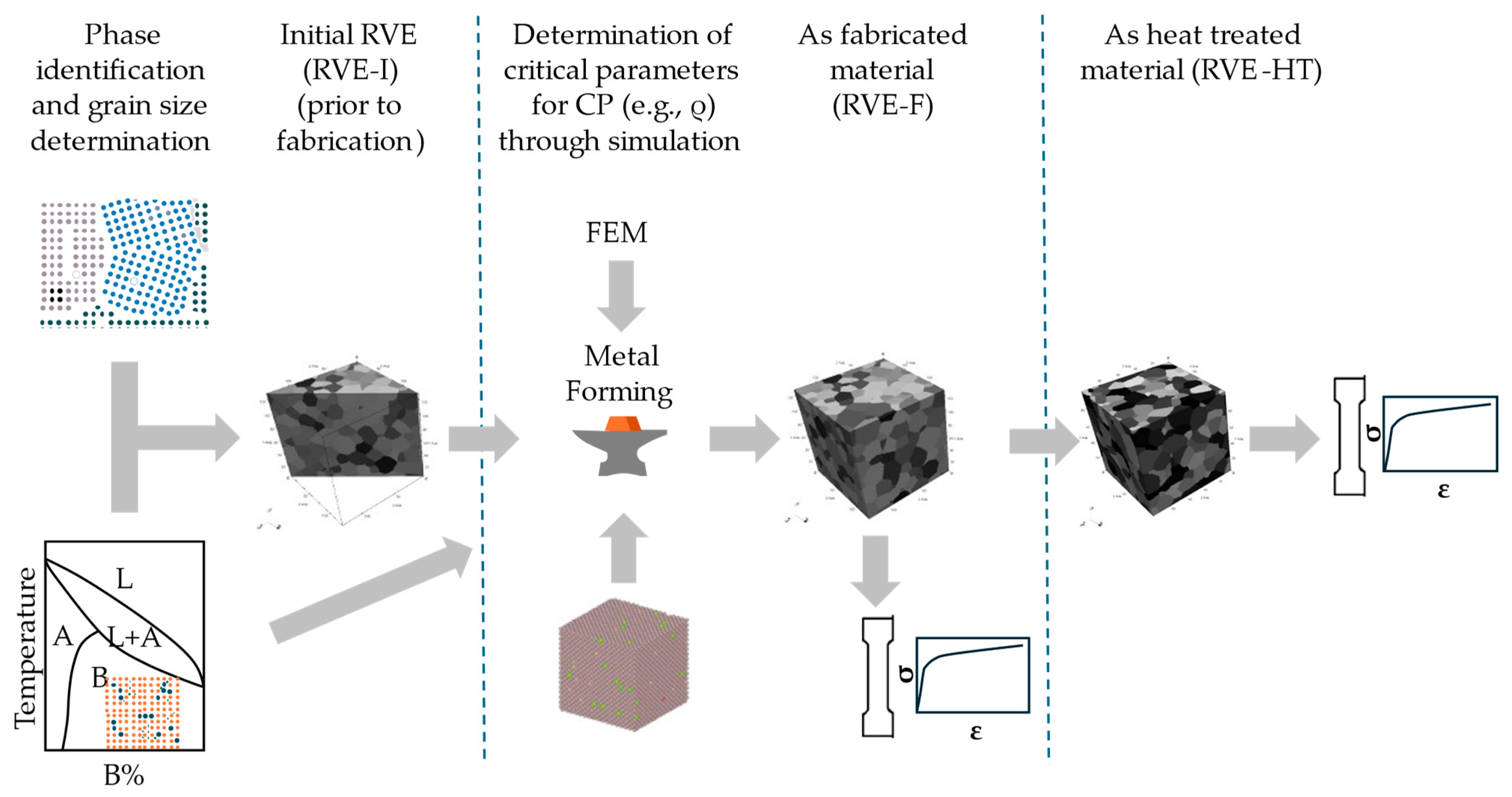
Figure 1 shows the three distinct phases of the approach. In Phase I, the initial RVE (RVE-I) is designed, and the relevant models are calibrated. In Phase II, the focus shifts onto the impact of the forming process on the microstructure and material parameters (such as the dislocation density). These parameters, along with the deformed microstructure, are utilized as input data for the thermal treatment. In turn, Figure 2 shows the step-by-step process along with the methodologies utilized for the identification of the needed parameters, highlighting the hierarchical and iterative nature of the proposed framework.

Figure 1.
Steps for determining the final RVE (microstructure and properties) based on the thermomechanical history of the material.
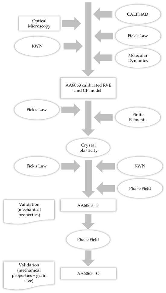
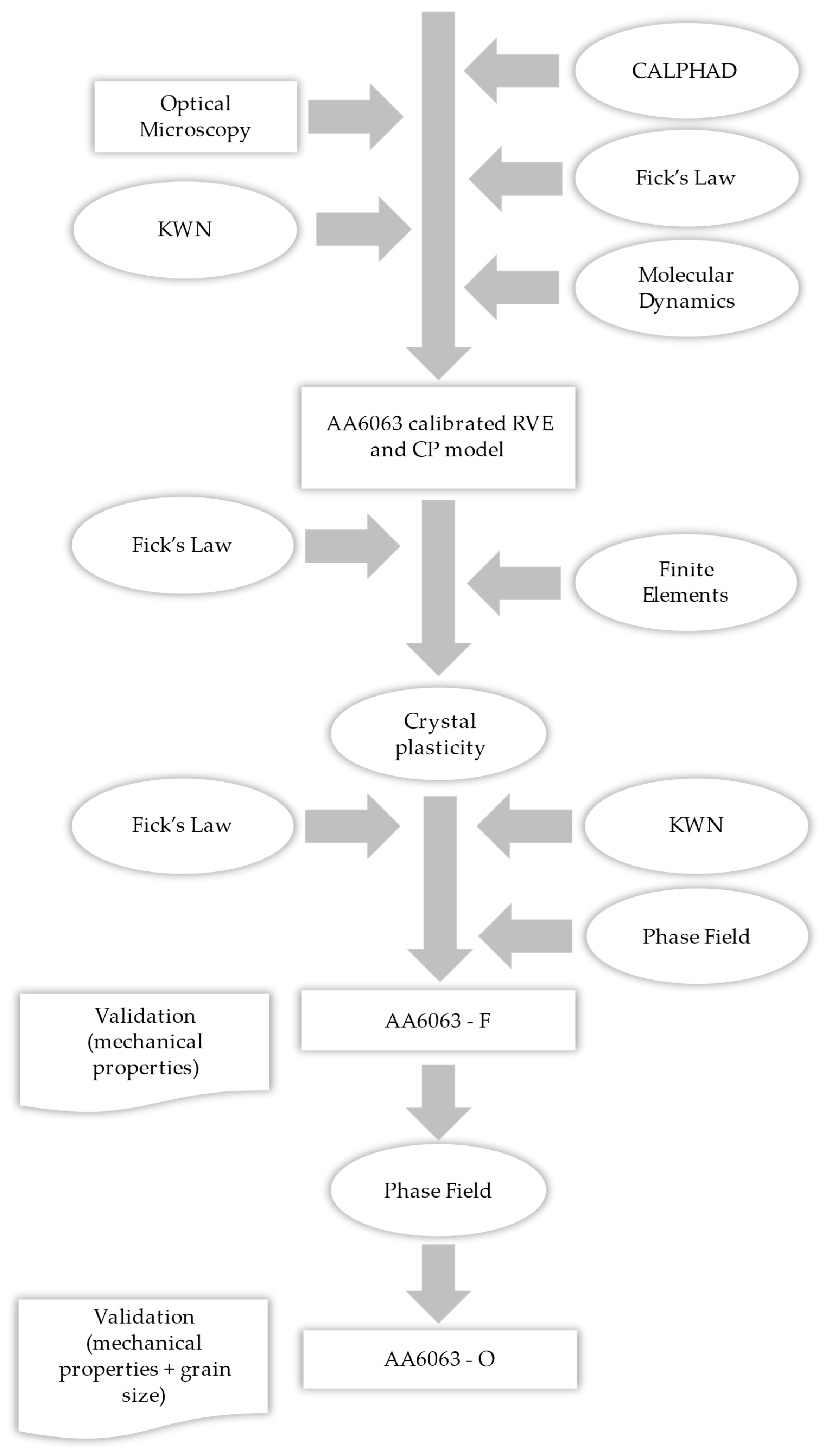
Figure 2.
Schematic of the flow of the processes.
3. Results and Discussion
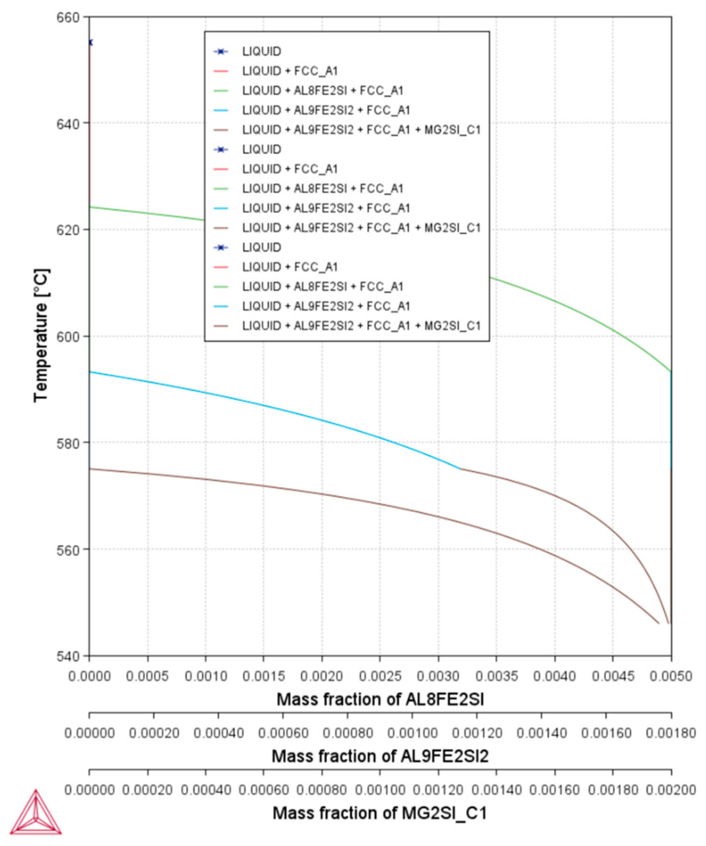
Figure 3 shows the pseudo-binary phase diagram, as calculated with the composition of Table 1. The dotted lines signify the Mg% present in the material whereas the circle signifies the hot extrusion temperature (550 °C). It becomes evident that, under equilibrium and at room temperature conditions, four distinct phases are present within the microstructure. The α-phase/matrix, which is the aluminum phase; the Mg2Si precipitates, which contributes to mechanical strengthening of the material; and the two AlFeSi constituent phases. During homogenization, the Mg2Si precipitates are re-diluted within the matrix, with the two AlFeSi phases to be retained. It is possible, in combination with the heat input from the deformation and friction, for the β-phase to be partly diluted during forming since the operation is performed at a temperature near its solvus.
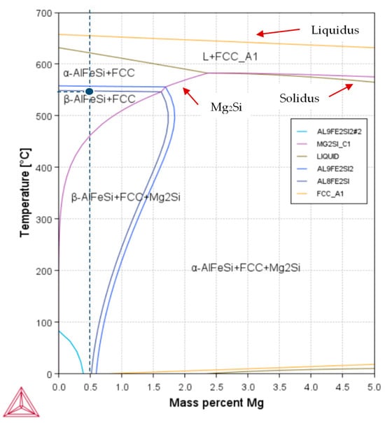
Figure 3.
Pseudo-binary Al–Mg phase diagram for the selected AA6063 chemical composition.
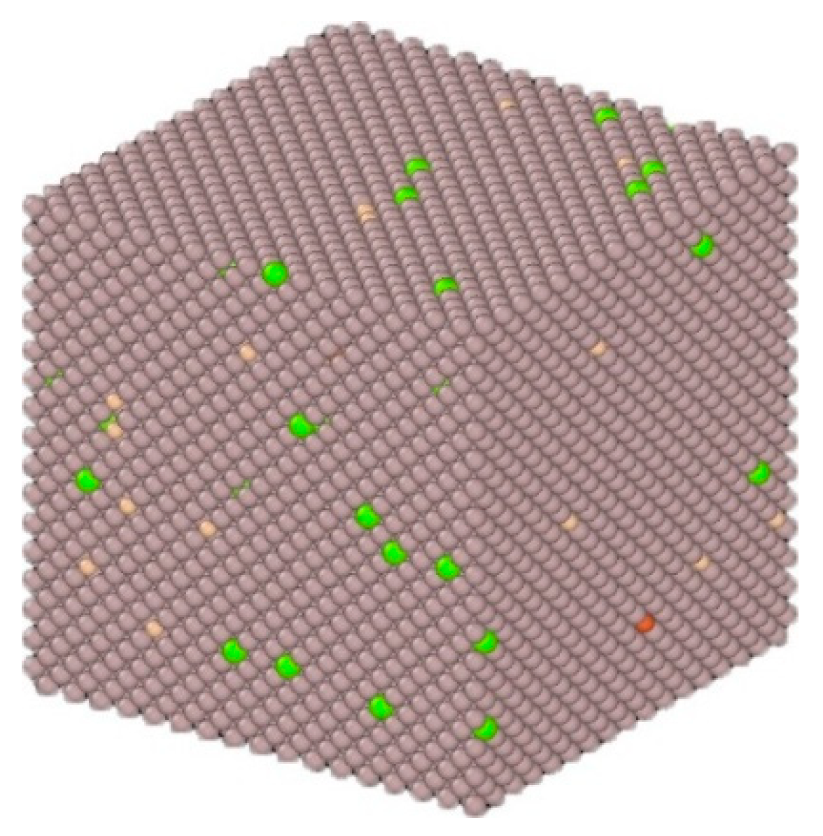
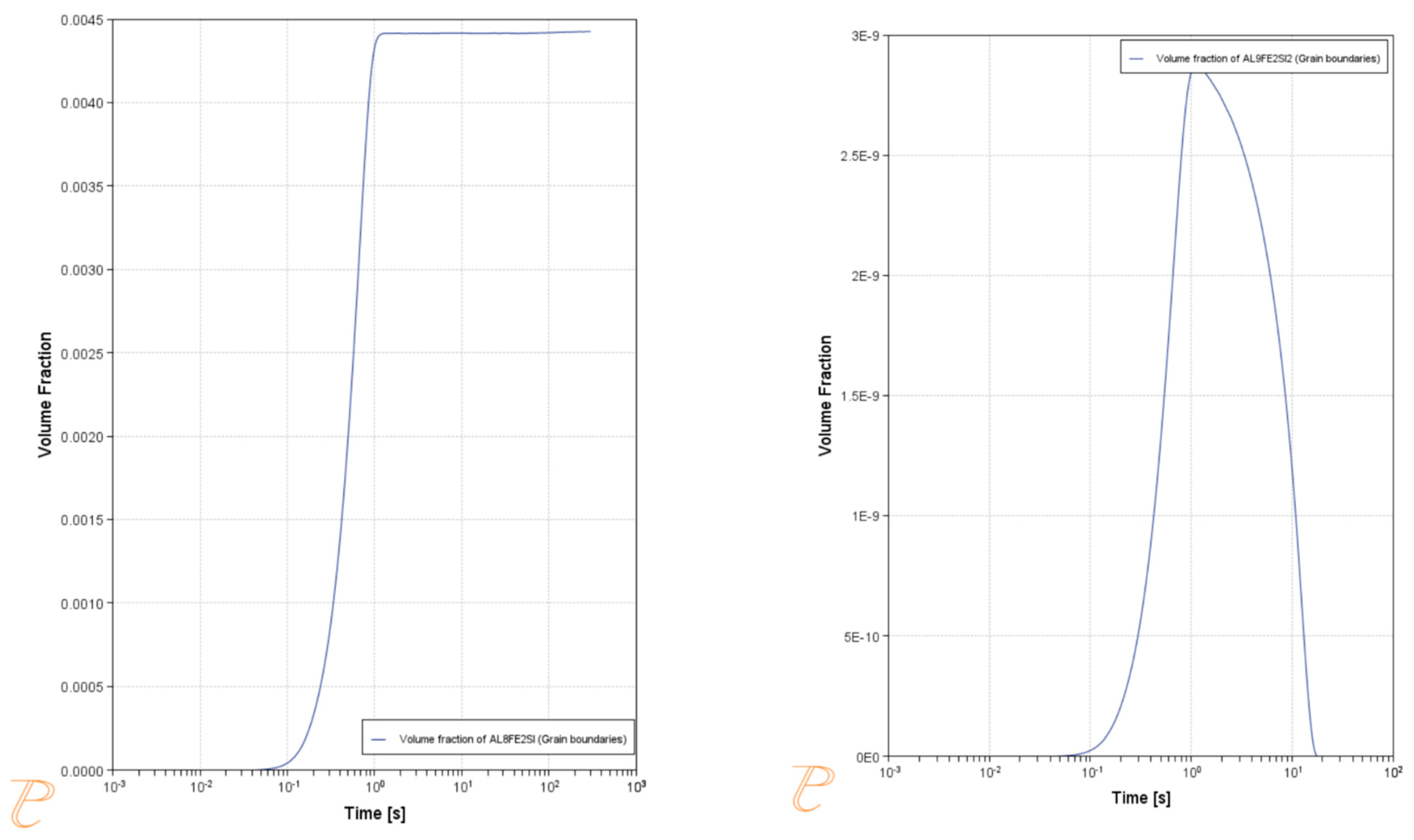
Through ThermoCalc’s precipitation add-on, the starting volume fraction of the three precipitate phases is calculated as a fraction of the cooling rate. This is exhibited in Figure 4, where it is shown that the combined fraction of the AlFeSi phases is significantly lower than 1%. This result was consistent with Scheil calculations (Figure 5). In combination with their small size and minimal influence on mechanical properties, this allows for the assumption of the mean field approach in favor of computational efficiency, since it would require a much more detailed grid. This fully diluted scenario was also utilized in the case of molecular dynamics, where the atoms were distributed randomly across the domain (Figure 6). The parameters for these simulations were in accordance with the relevant literature [23].
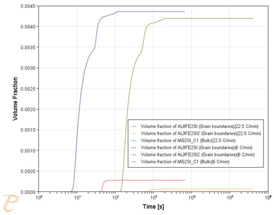
Figure 4.
Evolution of the volume fraction of the two precipitates during cooling from 700 °C with 6 °C/m and 22.5 °C/m. These results are indicative of their volume fraction during casting.
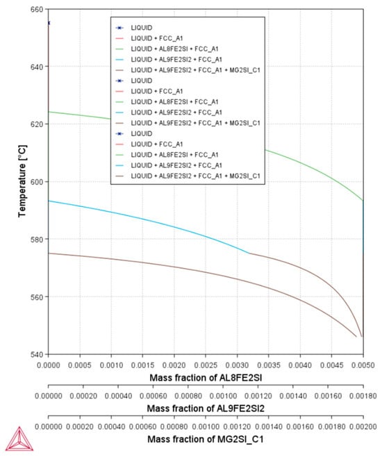
Figure 5.
Volume fraction of precipitants during solidification according to the Scheil model.
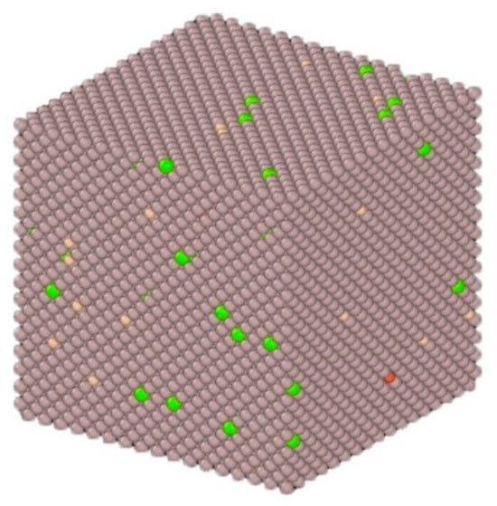
Figure 6.
Solid solution distribution as imported in LAMMPS. The different colors represent different types of atoms found in the system.
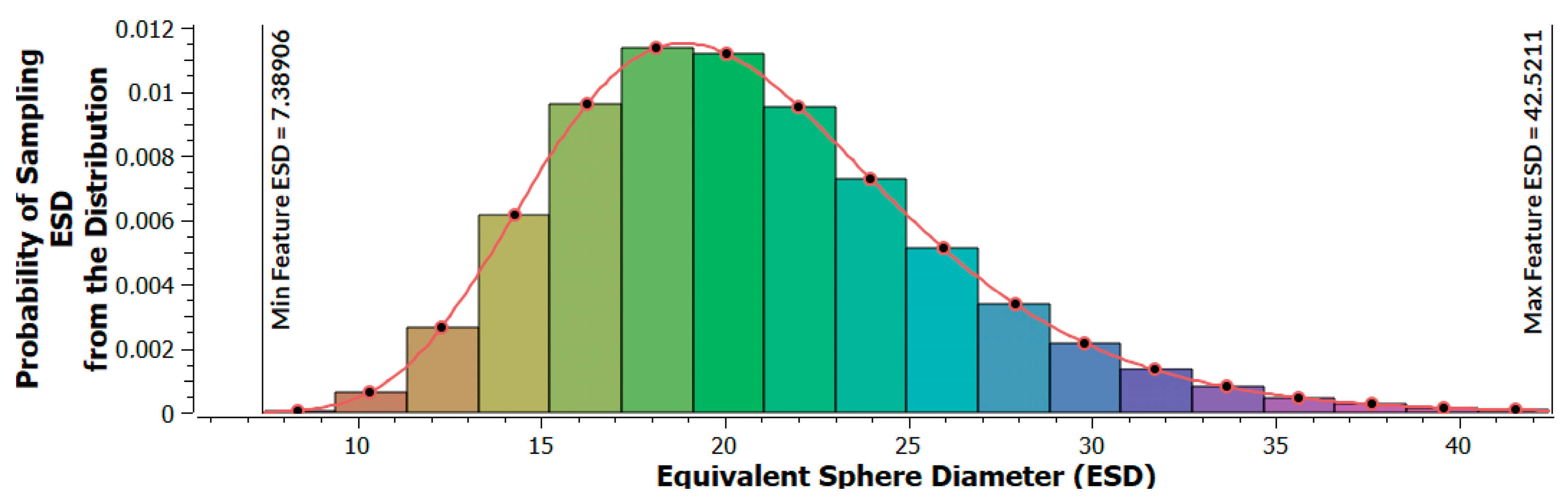
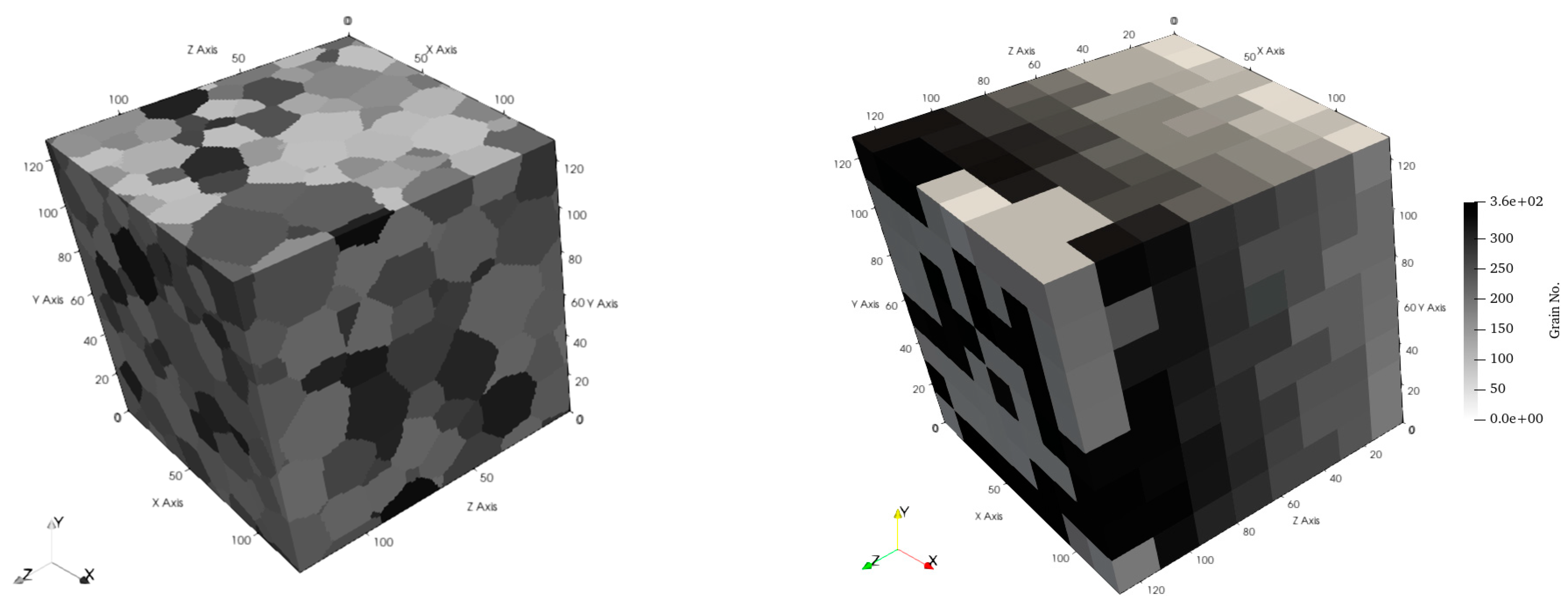
As mentioned earlier the RVE was created via Dream3D. The grain size distribution is portrayed in Figure 7 whereas Figure 8 showcases the created 3D RVE. The precipitation content was re-examined to confirm that the parameters considered to allow the mean field approach were still in place, i.e., very small volume fractions of the α-AlFeSi and β-AlFeSi (Figure 9). The mechanical properties during extrusion, i.e., at ~550 °C, were calibrated against literature data [24]. As expected, the yield strength of the material was found to be reduced as the temperature raises due to the increased movement speed of dislocations within the lattice.

Figure 7.
Grain size distribution of the cast material.
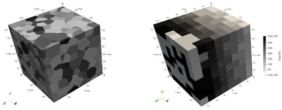
Figure 8.
Resulting RVE with a grid of 128 × 128 × 128 (for illustration purposes) and 8 × 8 × 8 used in the simulations.
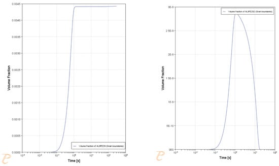
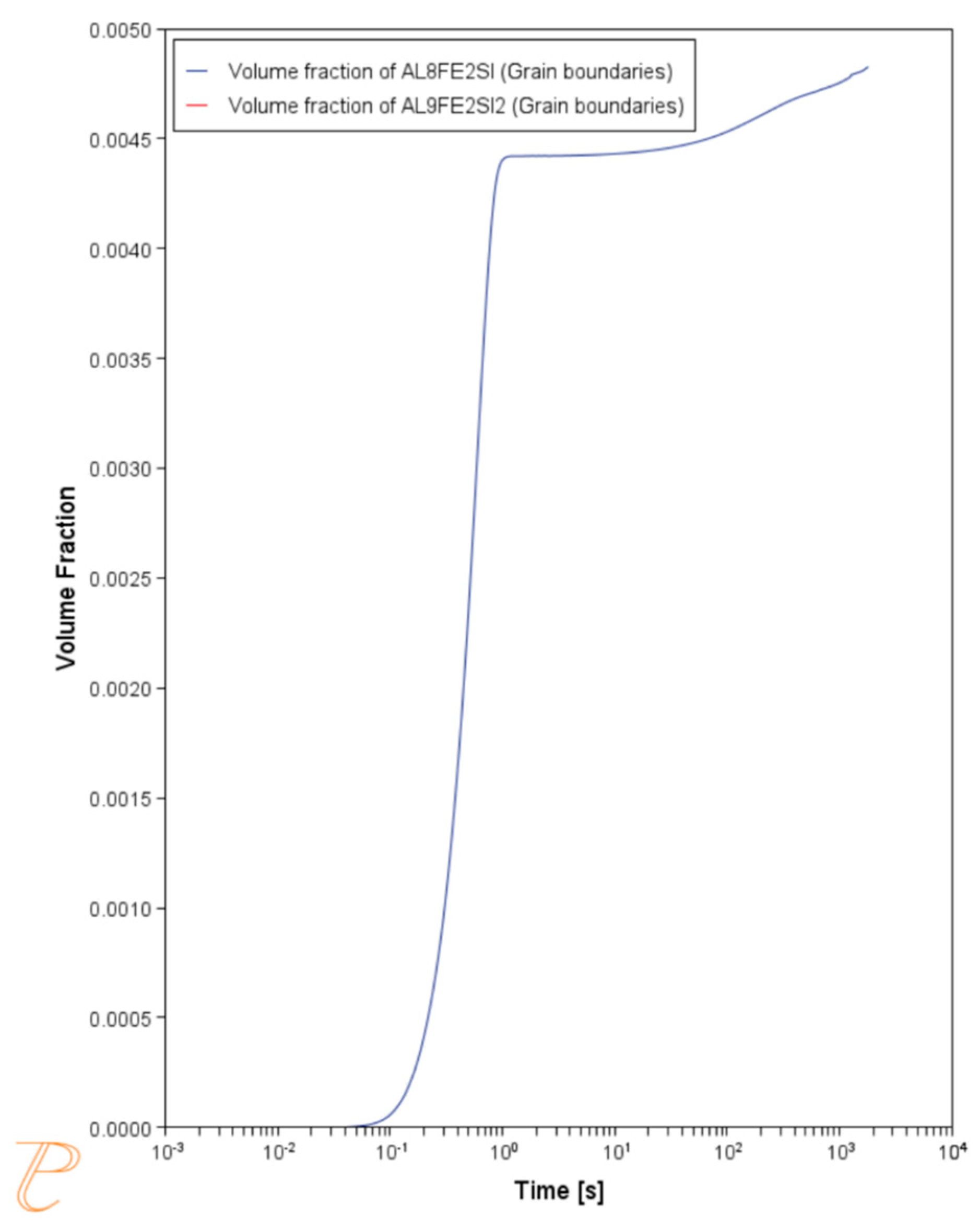
Figure 9.
Volume fraction of the Al8Fe2Si and the Al9Fe2Si2 precipitates during isothermal holding at 550 °C (extrusion temperature).
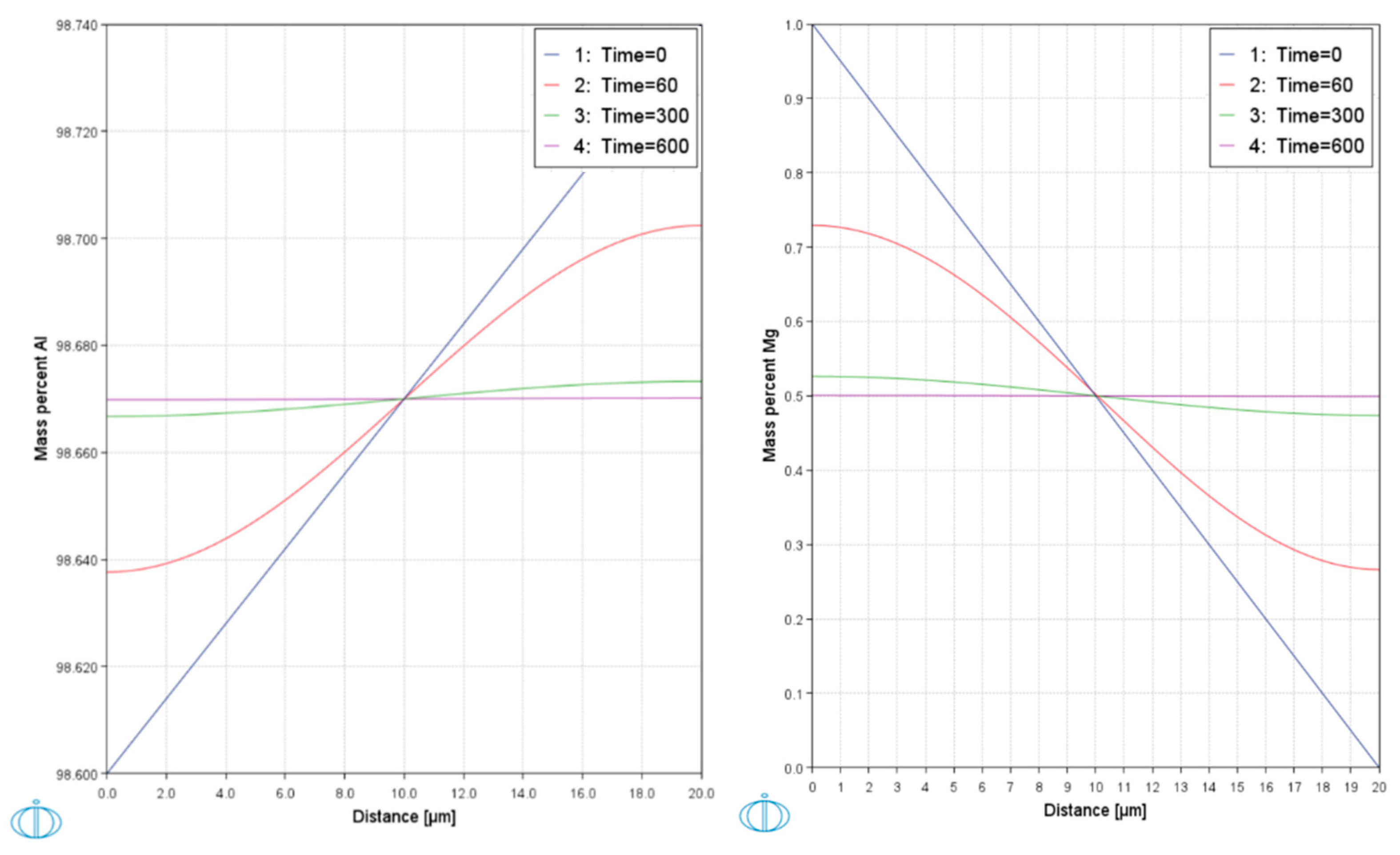
The hot forming is rather short in duration, with an order of magnitude around 1’. To examine the effect of the forming temperature on the microstructure and namely possible recrystallization, this duration was compared to the diffusion speed of the Al and Mg within the alloy’s crystals. These calculations were performed through the TC diffusion module (DICTRA) and are shown in Figure 10. For these computational experiments, the segregation profile within a grain (20 μm) was considered. In both scenarios, the time required to cancel out the segregation was about 10’, an order of magnitude higher than the duration of the extrusion process. This, combined with the stresses applied during the process, helped with the assumption that no grain growth takes place while the metal is being formed. Based on this assumption, the use of the CP model was able to study the impact of the extrusion process on the grain structure without needing to be coupled with an embedded PF model to study the process of recrystallization. After forming, the cooling rate does impact the extent of recrystallization within the material. Typically, it is cooled with 0.2 °C/s [25], which corresponds to a cooling duration of about 45’. For the above duration, the volume fraction of the AlFeSi phases was recalculated and as expected were found to not exceed the 0.5% mark (Figure 11).
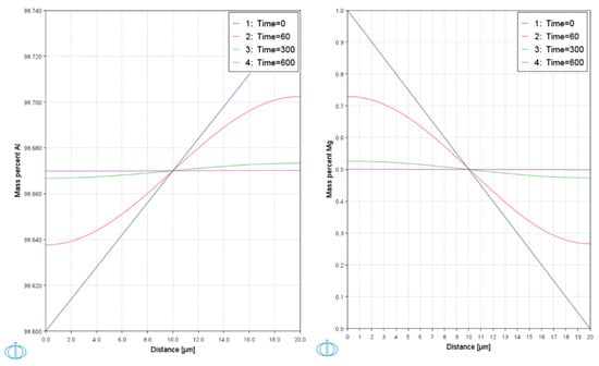
Figure 10.
Results from diffusion calculations of Al and Mg within the lattice considering the total alloying content (the duration shown in the legend refers to seconds).
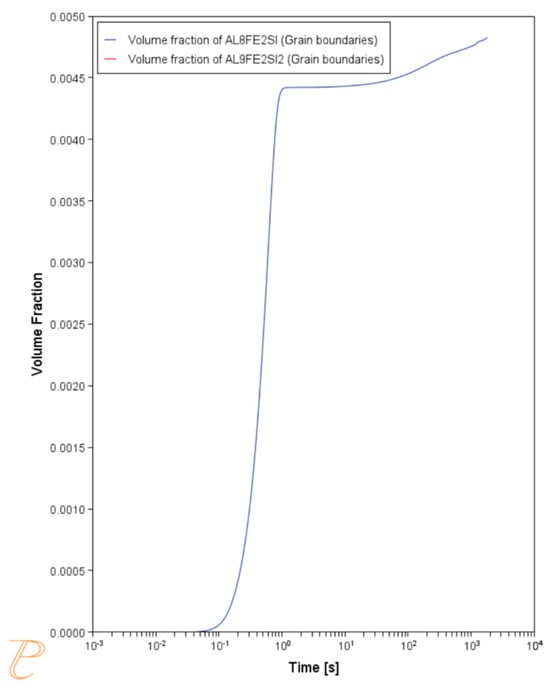
Figure 11.
Volume fraction of the two AlFeSi phases during a 30’ cooling from the extrusion temperature (550 °C).
In Figure 12, the results from the computational experiments are shown against data from the tensile testing, where it is evident that the maximum divergence is not significant.
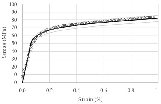
Figure 12.
Comparison between experimental (×) and calculated (-) stress–strain curves of the AA6063-F along with ±5% deviation markers (in light grey).
The next step in the production process, after deformation, is the homogenization of the material prior to aging. Grain growth is expected to occur during this stage. As previously mentioned, after the forming has concluded and during cooling, there is enough time for recrystallisation and grain growth to proceed. This was taken into account, as shown in Figure 13, where the RVE is shown both in the -F (left) and -O (right) tempers.
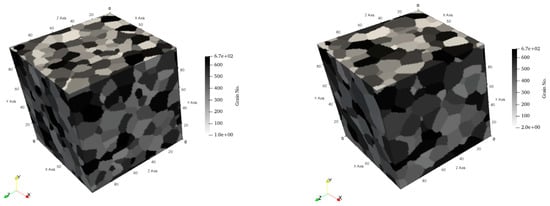
Figure 13.
The RVE before -F (left) and -O after (right) the second homogenization process.
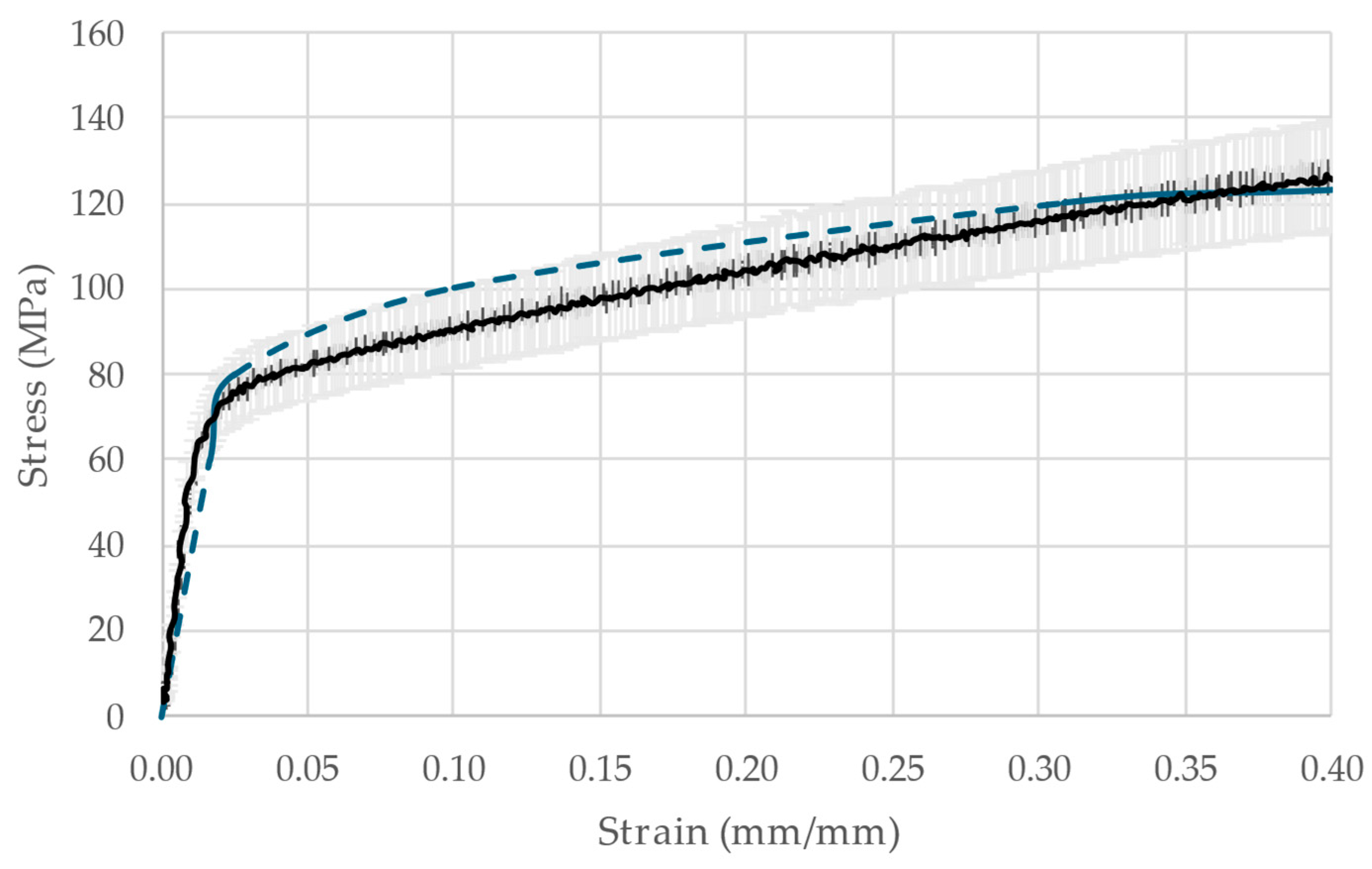
The -O temper microstructure (the grain size of which was found to be in accordance with experimental findings from the literature [10]) will be for the most part retained during aging with the addition of the precipitates that contribute to hardening. A further validation point is the order of magnitude of the dislocation density, calculated from MICRESS, which was in accordance with the literature on metallic systems [26,27]. The stress-strain curve of the AA6063-O is compared to available literature data [28] in Figure 14.
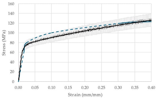
Figure 14.
Over-imposed stress–strain curves for AA6063-O calculated (continuous black line) vs. literature data (blue dotted line). The grey area signifies a ±10% divergence.
A key limitation of the CP model used in this framework is the absence of a fracture criterion. As a result, the RVE does not capture the onset of necking, leading to deformation predictions that extend beyond realistic failure limits. However, for metal forming simulations, this is not a significant drawback as the material typically surpasses its yield strength but does not progress into the necking region during processing. Additionally, this limitation can be “manually” addressed by examining the strain and stress evolution within the material. Specifically, the time step at which the first calculation exceeds the expected tensile strength can be conservatively taken as the onset of necking. It should be noted that physics-based fracture criteria are currently being developed by various teams. Alternatively, macroscale finite element analysis (FEA) simulations can use this reference point when designing the process.
4. Conclusions
The ability to predict microstructural evolution with high accuracy can significantly reduce trial-and-error in industrial metal processing, enabling cost and time savings. This study demonstrates the effectiveness of a metallurgically informed multiscale computational framework for predicting mechanical responses in metal forming. By integrating computational thermodynamics, phase-field modeling, molecular dynamics, FEM, and crystal plasticity, a high predictive accuracy was achieved while the reliance on experiments was reduced. The simulation workflow was validated based on the extrusion of AA6063. During the extrusion and subsequent homogenization, the utilization of the same thermodynamical tools allowed for a through-process simulation.
Specifically, the pseudo-binary diagram of the alloys was calculated and validated with results from scanning electron microscopy. The impact of each thermal treatment on the volume fraction of the various microstructural constituents was quantified via the KWN model, whereas their effect on the aluminum’s grain size and dislocation density was studied via phase field modelling. Similarly, the effect of mechanical loading on the microstructure and dislocation density was studied through crystal plasticity.
Due to the small size of the secondary phases (AlFeSi) and their minimal impact on the mechanical properties of the alloy, a mean field approach was selected. For the extrusion stage, this simplification is not expected to alter the results while allowing for a coarser grid and thus reducing computational costs. A full field approach would be required to study the impact of aging on the final mechanical properties in order to capture the effect of the β-phase precipitation characteristics. Even in this case, the simplification of the AlFeSi phases would not alter the mechanical response. The location of the precipitation, as well as their size, can be studied through phase field modelling, whereas the temperature and duration of the aging can be selected based on the calculated phase diagram and from relevant computational experiments with the KWN.
Prior to the first homogenization stage is the casting and solidification of the material. The influence of the relevant parameters on grain size and microstructural constituents can be studied through phase field modeling.
By performing these two extra stages, the whole process can be studied exclusively via simulation, further reducing the need for experimental results during the intermediate stages. This approach lays the foundation for more efficient, experiment-free workflows in material and process design.
Author Contributions
Conceptualization, S.P.; methodology, S.P. and V.L.; formal analysis, V.L.; investigation, V.L.; resources, S.P.; data curation, V.L.; writing—original draft preparation, V.L.; writing—review and editing, S.P.; visualization, V.L.; supervision, S.P. All authors have read and agreed to the published version of the manuscript.
Funding
This research was partially funded by the Bodosakis Foundation’s scholarship program.
Data Availability Statement
No new data were created.
Acknowledgments
The authors would like to thank I. Dalezios and A. Loubani for executing some of the calculations.
Conflicts of Interest
The authors declare no conflicts of interest.
References
- Hooke, R. De Potentia Restitutiva or of Spring Explaining the Power of Springing Bodies; Royal Society: London, UK, 1678. [Google Scholar]
- Hall, E.O. The Deformation and Ageing of Mild Steel: III Discussion of Results. Proc. Phys. Soc. Sect. B 1951, 64, 747. [Google Scholar] [CrossRef]
- Petch, N.J. The Cleavage Strength of Polycrystals. J. Iron Steel Inst. 1953, 174, 25–28. [Google Scholar]
- Rhines, F.N. Microstructure-property relationships in materials. Metall. Trans. A 1977, 8A, 127–133. [Google Scholar] [CrossRef]
- Taylor, G.I.; Elam, C.F. The distortion of an aluminium crystal during a tensile test. Proc. R. Soc. Lond. A Math. Phys. Eng. Sci. 1923, 102, 126–135. [Google Scholar]
- Taylor, G. The Mechanism of Plastic Deformation of Crystals. Part I. Theoretical. Proc. R. Soc. Lond. Ser. A Contain. Pap. A Math. Phys. Character (1905–1934) 1934, 145, 362–387. [Google Scholar]
- Qayyum, F.; Guk, S.; Prahl, U. Applications of Crystal Plasticity in Forming Technologies. Crystals 2022, 12, 1466. [Google Scholar] [CrossRef]
- Van Houttee, P.; Kanjarla, A.K.; Van Bael, A.; Seefeldt, M.; Delannay, L. Multiscale modelling of the plastic anisotropy and deformation texture of polycrystalline materials. Eur. J. Mech. A/Solids 2006, 25, 634–648. [Google Scholar] [CrossRef]
- Xia, C.-H.; Wang, K.; Song, X.; Pan, W.; Li, W.; Wu, H.-H.; Dou, K.; Xu, Y.; Tong, Z.; Lv, S.; et al. Overview of Multi-Scale Simulation Techniques for Three Typical Steel Manufacturing Processes. Materials 2024, 17, 3173. [Google Scholar] [CrossRef]
- Buades, L.M.R.; Persson, M.P. Process–Structure–Property Simulation Approach to the Estimation of Tensile Anisotropy in 3D Printed Meta stable β Titanium Alloy. Integr. Mater. Manuf. Innov. 2023, 12, 338–348. [Google Scholar] [CrossRef]
- Motaman, S.A.H.; Kies, F.; Koehen, P.; Letang, M.; Lin, M.; Molotnikov, A.; Haase, C. Optimal Design for Metal Additive Manufacturing: An Integrated Computational Materials Engineering (ICME) Approach. In Proceedings of the 2ND Asia-Pacific International Conference on Additive Manufacturing 2019, Melbourne, Australia, 30 June–3 July 2025; Volume 72. [Google Scholar]
- Sarafoglou, P.; Haidenemopoulos, G. Phase Fraction Mapping in the as-cast microstructure of extrudable 6xxx aluminum alloys. Int. J. Mater. Res. 2014, 105, 1202–1209. [Google Scholar] [CrossRef]
- Souissi, S.; Barhoumi, H.; Amar, M.; Elhalouani, F. Microstructure Evolution and Mechanical Properties of the T6 Heat Treated AA6063 Alloy Produced by Squeeze Casting. Phys. Met. Metallogr. 2019, 120, 806–812. [Google Scholar] [CrossRef]
- Vazdirvanidis, A. Study of the Thermal Treatments of Industrial Extrudable AA6XXX to Optimise Strength and Crashworthiness. Ph.D. Dissertation, NTUA, Zografos, Athens, 2016. (In Greek). [Google Scholar]
- Andersson, J.O.; Helander, T.; Höglund, L.; Shi, P.F.; Sundman, B. Thermo-Calc & DICTRA, Computational tools for materials science. Calphad 2002, 26, 273–312. [Google Scholar]
- Groeber, M.A.; Jackson, M.A. DREAM.3D: A Digital Representation Environment for the Analysis of Microstructure in 3D. Integr. Mater. Manuf. Innov. 2014, 3, 56–72. [Google Scholar] [CrossRef]
- Haouala, S.; Lucarini, S.; LLorca, J.; Segurado, J. Simulation of the Hall-Petch effect in FCC polycrystals by means of strain gradient crystal plasticity and FFT homogenization. J. Mech. Phys. Solids 2020, 134, 103755. [Google Scholar] [CrossRef]
- Cantergiani, E.; Falkinger, G.; Mitsche, S.; Theissing, M.; Klitschke, S.; Roters, F. Influence of Strain Rate Sensitivity on Cube Texture Evolution in Aluminium Alloys. Metall. Mater. Trans. A 2022, 53, 2832–2860. [Google Scholar] [CrossRef]
- Mangal, A.; Holm, E.A. Applied machine learning to predict stress hotspots I: Face centered cubic materials. Int. J. Plast. 2018, 111, 122–134. [Google Scholar] [CrossRef]
- Eiken, J.; Böttger, B.; Steinbach, I. Multiphase-field approach for multicomponent alloys with extrapolation scheme for numerical application. Phys. Rev. 2006, 73, 066122. [Google Scholar] [CrossRef]
- Roters, F.; Diehl, M.; Shanthraj, P.; Eisenlohr, P.; Reuber, C.; Wong, S.L.; Maiti, T.; Ebrahimi, A.; Hochrainer, T.; Fabritius, H.-O.; et al. DAMASK—The Dusseldorf Advanced Material Simulation Kit for modeling multi-physics crystal plasticity, thermal, and damage phenomena from single crystal up to the component scale. Comput. Mater. Sci. 2019, 158, 420–478. [Google Scholar] [CrossRef]
- Thompson, A.P.; Aktulga, H.M.; Berger, R.; Bolintineanu, D.S.; Brown, W.M.; Crozier, P.S.; In’t Veld, P.J.; Kohlmeyer, A.; Moore, S.G.; Nguyen, T.D.; et al. LAMMPS—A flexible simulation tool for particle-based materials modeling at the atomic, meso, and continuum scales. Comp Phys Comm 2022, 271, 108171. [Google Scholar] [CrossRef]
- Jelinek, B.; Groh, S.; Hormstemeyer, M.F.; Houze, J.; Kim, S.G.; Wagner, G.J.; Moitra, A.; Baskes, M.I. Modified embedded atom method potential for Al, Si, Mg, Cu and Fe alloys. Phys. Rev. B 2012, 85, 245102. [Google Scholar] [CrossRef]
- Francesco, L.; Oystein, G.; Lise, S.; Filippo, B. High temperature tensile properties of AA6082 filler wire used for solid-state joining. Procedia Struct. Integr. 2020, 25, 348–354. [Google Scholar]
- Benjunior, B.; Ahmad, A.; Rashidi, M.M.; Reza, M. Effect of Different Cooling Rates Condition on Thermal Profile and Microstructure of Aluminium 6061. Procedia Eng. 2017, 184, 298–305. [Google Scholar] [CrossRef]
- Thirathipviwat, P.; Song, G.; Jayaraj, J.; Bednarcik, J.; Wendrock, H.; Gemming, T.; Freudenberger, J.; Nielsch, K.; Han, J. A comparison study of dislocation density, recrystallization and grain growth among nickel, FeNiCo ternary alloy and FeNiCoCrMn high entropy alloy. J. Alloys Compd. 2019, 790, 266–273. [Google Scholar] [CrossRef]
- Bodyakova, A.; Dolzhenko, A.; Marina, O.; Zhilyaev, A.P.; Belyakov, A.; Kaibyshev, R. Annealing Behavior and Kinetics of Primary Recrystallization of Copper. Defect Diffus. Forum 2018, 385, 343–348. [Google Scholar]
- Reza, B.; Michel, G.; Mario, F.; Guillaume, D.A. Numerical Studies on the Production of Variable Thickness Aluminium Tubes for Transportation Purposes. In Proceedings of the SAE2010 World Congress Technical Papers, Detroit, MI, USA, 13 April 2010. [Google Scholar]


Disclaimer/Publisher’s Note: The statements, opinions and data contained in all publications are solely those of the individual author(s) and contributor(s) and not of MDPI and/or the editor(s). MDPI and/or the editor(s) disclaim responsibility for any injury to people or property resulting from any ideas, methods, instructions or products referred to in the content. |
© 2025 by the authors. Licensee MDPI, Basel, Switzerland. This article is an open access article distributed under the terms and conditions of the Creative Commons Attribution (CC BY) license (https://creativecommons.org/licenses/by/4.0/).