Article

Optimal Linear Precodings for Multi-Color, Multi-User Visible Light Communication System with Fairness Considerations

National Digital Switching System Engineering Technological Research Center, Zhengzhou 450000, China
*
Author to whom correspondence should be addressed.
Crystals 2018, 8(11), 404; https://doi.org/10.3390/cryst8110404 (registering DOI)
Submission received: 18 September 2018 / Revised: 16 October 2018 / Accepted: 23 October 2018 / Published: 25 October 2018
(This article belongs to the Special Issue Advanced LED Solid-State Lighting Optics)

Abstract

:
With fairness consideration, optimal linear precoding designs for multi-color, multi-user visible light communication (VLC) systems are presented in this paper. Utilizing both the spatial and multi-color resources, the precoding designs are proposed to mitigate the impact of the multi-user interference (MUI) and the multi-color crosstalk. With the constraints of chromaticity, luminance, and signal range, the precoding designs are formulated to achieve the max-min fairness and the maximum sum-rate. Since the closed-form expression for the capacities is not available, the lower and upper bounds are chosen as the performance criterions. To make the optimization problems be easy to be solved by using standard optimization packages, the non-convex problems are cast into convex ones. Subsequently, algorithms are developed to find optimal solutions. Extensive simulation results indicate that the proposed precoding schemes outperform the conventional pseudo inverse method.

1. Introduction

Nowadays, visible light communication (VLC) technology using white light-emitting diodes (LEDs) has attracted tremendous attention in the world. Along with the rising and vigorous development of light-emitting diode (LED) lighting industry, VLC technology has been viewed as a potential solution to provide simultaneous indoor illumination and wireless data transmission due to its wide bandwidth and immunity to interference from electromagnetic sources [1,2,3,4,5,6]. Especially, due to the high security of VLC technology, it has been attractive for some special applications in electromagnetic-sensitive environments such as hospitals, airplanes, and the underground mining industry. Not only indoor communications, VLC also can render valuable services in many other application fields, e.g., indoor localization; device-to-device (D2D) communication with LCD screens or camera sensors; traffic control between traffic lights and vehicles or traffic signals between vehicles; and underwater wireless communications [7,8,9,10].
In VLC systems, there are two common types of white LEDs used for illumination: Phosphor-converted LEDs (pc-LEDs) and multi-chip LEDs [11]. Due to the limited modulation bandwidth of pc-LED, we consider multi-chip LEDs as the transmitter. Multi-chip LEDs exploit three or more LED chips to emit different monochromatic lights and mix them together according to the predefined ratio to produce white light, i.e., red-green-blue (RGB) LEDs [12,13]. What is more, the different monochromatic lights can be collaboratively used to transmit different data which improves the data rate of VLC systems [14,15,16,17,18].
To further increase the data rates, another method is multiple-input multiple-output (MIMO), which exploits the spatial multiplexing gain [19,20,21,22,23,24,25]. In these studies, the VLC networks are often regarded as broadcast networks, where multiple LEDs simultaneously serve multiple users. However high inter-channel interference (ICI) in VLC systems will degrade much of the performance. To mitigate the effect of ICI, precoding techniques are applied, which are extensively investigated in radio frequency (RF) broadcast channels [26,27,28,29].
It should be mentioned that adoption of those precoding techniques for VLC is not straightforward. For VLC systems, both communication performance and lighting quality should be taken into consideration. Considering the real and non-negative signal constraint in VLC systems, some optimal precoding design with either mean square error (MSE) or zero-forcing (ZF) criterion have been reported [30,31,32,33,34,35]. As the different monochromatic lights are collaboratively used to transmit different data, luminance constraint and color constraints should be taken into account additionally [36,37,38,39,40,41,42]. In case of single-PD receivers, the multi-user VLC systems for each user are regarded as MISO systems. In multi-color multi-user VLC systems, each user carries multi-color receivers and optical filters to separate each single-light. The VLC systems for each user are no longer MISO systems but MIMO systems.
In this paper, we firstly establish the system model of a multi-color multi-user VLC system. Then optimal precoding schemes are proposed with respect to lower and upper capacity bounds for the max-min fairness and the maximum sum-rate criterions, respectively. In the optimization problems, the chromaticity, luminance, and signal range constraints are all taken into consideration. To make these non-convex optimization problems be easily solved by CVX toolbox, a Matlab optimization software package to obtain the optimal solutions [43], we cast them into convex ones. The main contributions of this work are summarized as follows.
  • Unlike the single color VLC system, chromaticity constraint is taken into consideration, which we use correlated color temperature (CCT) to describe. Simulation results show that the CCT value has significant impact on the performance of the system.
  • Due to that each user is equipped with multi-color receivers, the system should be regarded as a MIMO system for each user. This makes the channel matrix and the objective function of the optimal precoding design more complicated than other VLC systems.
  • With slack variables and Taylor expansions, we cast the non-convex optimization problems into convex ones. Correspondingly the algorithms to find optimal solutions are developed.

2. Multi-Color Multi-User VLC Network Model

We consider a multi-color multi-user indoor VLC broadcast network. The network adopts N T multi-color LEDs as transmitters, which jointly serve K users simultaneously by means of precoding techniques. In the network, we assume that there are N c = 3 kinds of colors r , g , b . Here we use the notation c denotes the color number, where c = 1 means the red color, c = 2 means the green color, and c = 3 means the blue color. Each user is equipped with N c photodiode (PD) receivers and N c color optical filters to separate each single-light. For each user, the system can be regarded as a MIMO system, in which there are N c · N T antennas used as transmitter and N c antennas used as receiver. In this paper, we assume that there is uplink channel and the channel matrix is known by transmitters.

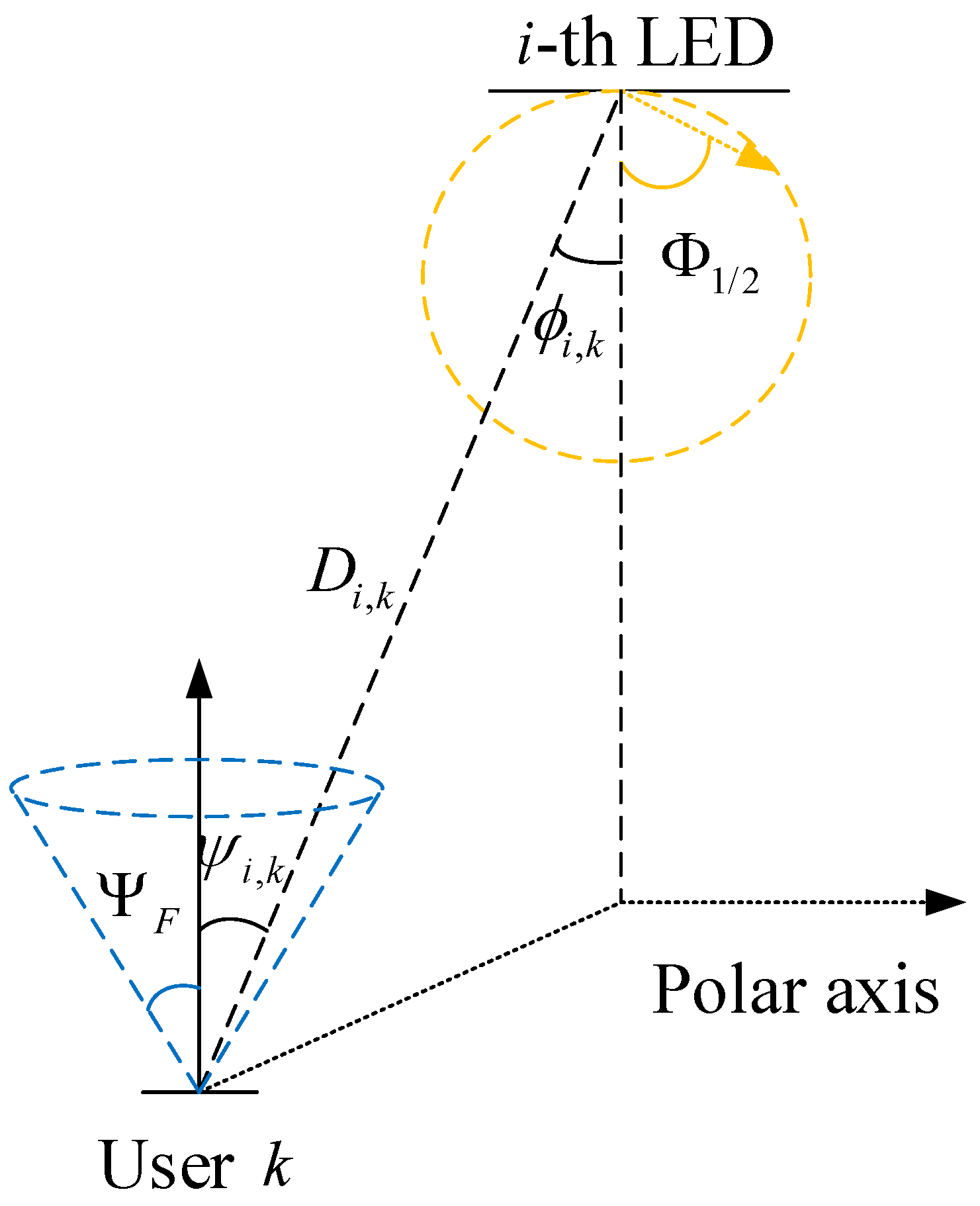
2.1. Lambertian Model

In general, a multi-color LED is assumed to be a Lambertian emitter. Here, we merely consider the line-of-sight (LOS) component [19]. For the i-th LED, as the multi-color chips are packed at the same LED, the distance between them is negligible compared to the distance between the LED and the receiver. So we assume h i , k , r = h i , k , g = h i , k , b = h i , k . As in Figure 1, the channel gain between the ith LED and kth user is determined by
h i , k = μ A R m 0 + 1 2 π D i , k 2 cos m 0 ϕ i , k cos ψ i , k , 0 ψ i , k Ψ F 0 , ψ i , k > Ψ F ,
where ϕ i , k is the angle of irradiance, ψ i , k is the angle of incidence, and m 0 is the order of the Lambertian emission defined as m 0 = ln 2 ln ( cos Φ 1 / 2 ) , where Φ 1 / 2 is the semi-angle at half power of an LED. D i , k depicts the distance between the ith LED and kth user. Each receiver consists of an optical concentrator, followed by a PD. Ψ F represents the width of the field of vision (FOV) at a receiver. μ is the responsivity of the PD. The effective receiver area of the detector A R is given by
A R = δ 2 sin 2 ( Ψ F ) A P D ,
where δ denotes the optical concentrator refractive index and A P D denotes the physical detection area of the detector.
If there is perfect optical filter which can separate light completely, the electrical-optical-electrical (EOE) channel gain matrix for each color between LEDs and all users can be expressed as
H r = H g = H b = h 1 , 1 h 2 , 1 h N T , 1 h 1 , 2 h 2 , 2 h N T , 2 h 1 , K h 2 , K h N T , K K × N T .

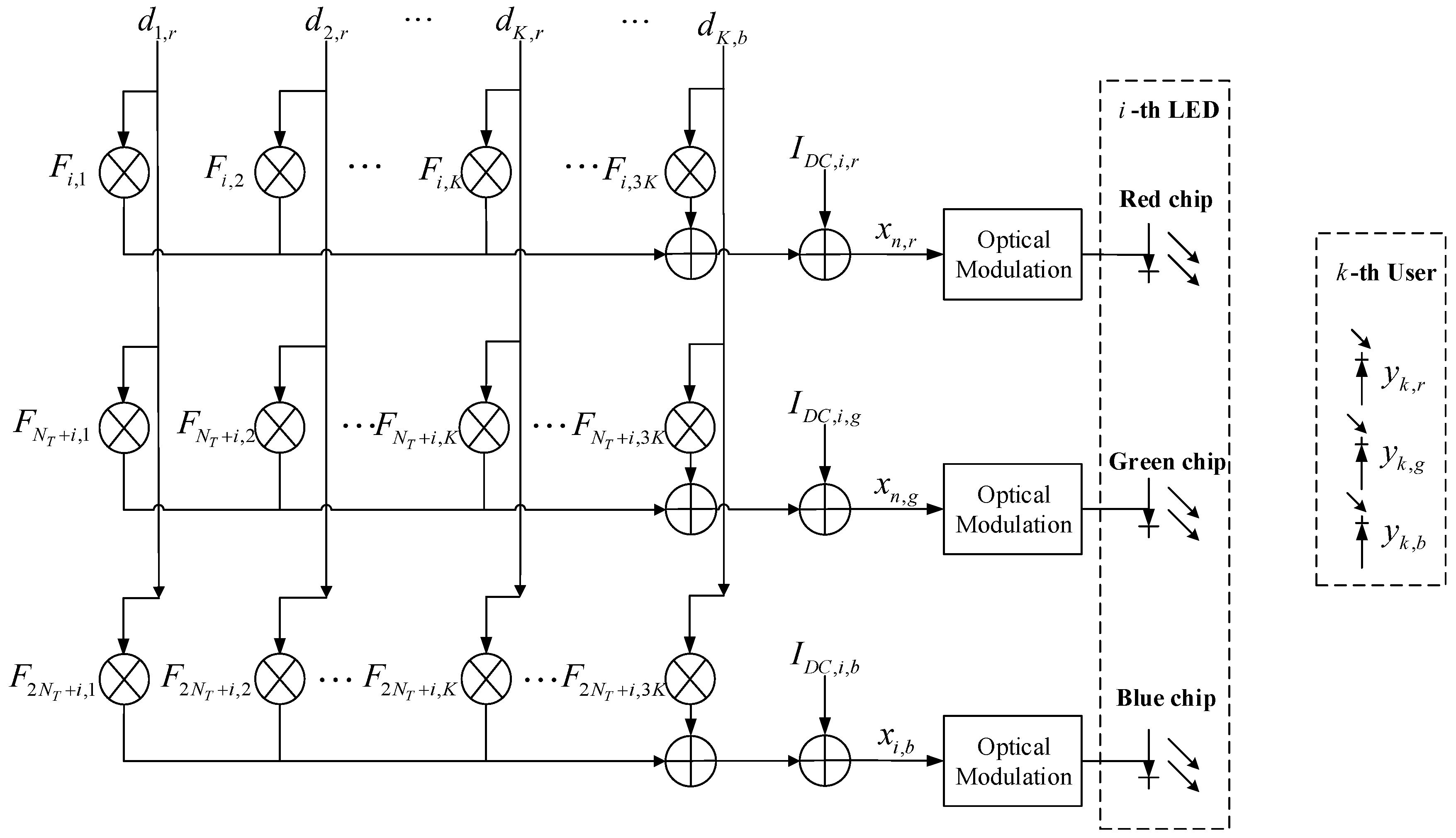
2.2. Precoding Model and Broadcast Transmission

Let d k , c R be the data symbol that is intended to kth user’s cth color. It is assumed that d k , c R is zero-mean, and without loss of generality, is normalized to the range of 1 , 1 [24]. The elements in the data vector for all users can be sorted by d = d r T , d g T , d b T T , where d c R K × 1 is the data vector in cth color and
d c = d 1 , c , d 2 , c , , d K , c T .
We assume that x = x r T , x g T , x b T T denotes the transmitted signal vector, where
x c = x 1 , c , x 2 , c , , x N T , c T .
Let F R N c · N T × N c · K be the precoding matrix. Figure 2 is used to describe the schematic diagram of precoding model at i-th LED. In Figure 2, F i , K denotes the element at the i-th row and K-th column of the matrix F . Then we can get
x = F · d + I D C ,
where I D C denotes the DC-bias vector to ensure the non-negativity of the input signal to LEDs. Since E F · d = 0 , the signal part F · d does not affect the average illumination level of the LEDs. Instead, it is uniquely determined by the DC-bias I D C .
Under the assumption that there is perfect optical filter which can separate light completely, for c-th color, as in (3), the received electrical signal vector can be written as
y c = H c · x c + n c ,
where y c = y 1 , c , y 2 , c , , y K , c T and y k , c denotes the received signal at the k-th user’s c-th color. n c denotes the additive white Gaussian noise (AWGN) following the distribution of N 0 , σ 2 I c . However, it should be mentioned that each color of the LED has a wide spectrum and they have overlapping each other. Eventhough each user is equipped with N c color optical filters, the color filters cannot separate light completely. Therefore, in a practical system, light through color filters contains the desired light and interference light. Here we use ξ 0 , 0.5 to characterize the interference ratio [44]. We assume that the signal leakage only occurs between two neighboring color bands due to their close frequencies. So the received electrical signal vector for each color can be written as
y r = 1 ξ H r · x r + ξ · H g · x g + n r ,
y g = 1 2 ξ H g · x g + ξ · H r · x r + ξ · H b · x b + n g ,
y b = 1 ξ H b · x b + ξ · H g · x g + n b .
Let y = y r T , y g T , y b T T , and n = n r T , n g T , n b T T , the received electrical signal vector can be written as
y = H · x + n ,
where
H = 1 ξ · H r ξ · H g 0 ξ · H r 1 2 ξ · H g ξ · H b 0 ξ · H g 1 ξ · H b N c · K × N c · N T .
For the convenience of expression, we let L = N c × K . Then we can replace the subscript k and c with the subscript l [ 1 , L ] . Then the data vector and the received electrical signal vector can be rewritten as
d = d 1 , d 2 , , d l , , d L L × 1 T ,
y = y 1 , y 2 , , y l , , y L L × 1 T ,
where l / K = c denotes the number of the color, l K · c 1 = k denotes the number of the user, and · denotes round down operator. Then the element of the received electrical signal vector can be given by
y l = H l F l d l + H l j = 1 , j l L F j d j + H l I D C + n l ,
where H l denotes the lth row of H , F l denotes the lth column of F . As seen in (15), the first term H l F l d l is the desired signal, while the second term H l j = 1 , j l L F j d j is the multi-user interference (MUI). The third term I D C represents the DC current. After removing the DC current by AC coupling and removing the MUI via ZF precoders, the received signal can be written by
y l = H l F l d l + n l .

2.3. Generalized Inverse and Pseudo Inverse

The ZF precoding algorithm aims to completely remove the MUI via the construction of the precoder F , i.e.,
H l F j = 0 , l j .
In other words, we can rewrite the ZF constraint in (17) as
HF = diag q 1 q L ,
whose q l represents the channel gain of the l-th sub-channel. The precoding matrix F can be expressed in the form
F = H diag q 1 q L ,
where H denotes the generalized inverse of H , which can be any matrix that satisfied H H H = H . Generally, the generalized inverse is not unique. In RF systems, the pseudo-inverse H = H T H H T 1 is the optimum precoder under the total average power constraint [26]. The pseudo-inverse is one of the special generalized inverse, but not necessary to be the optimal one in VLC systems because of the different signal constraint.

3. Problem Formulation

3.1. Illumination and Communication Constraints

3.1.1. Chromaticity Constraint

For the cth color of the ith LED, let the luminous flux be L i , c and λ c · L i , c = I D C , i , c , where λ c is the constant coefficient to convert the luminous flux to the forward current. The chromaticity coordinate of the single-color light is ( x i , c , y i , c ) . We assume that all of the LEDs are the same and x i , c , y i , c = x j , c , y j , c = x c , y c , i , j 1 , N T . The ith LED’s desired chromaticity coordinate of the mixed light ( x ^ i , y ^ i ) are changed with the CCT value. It can be computed by using the relationship below [45]
x ^ i = a T L i b T L i = c = 1 N c x c y c L i , c c = 1 N c 1 y c L i , c ,
y ^ i = 1 T L i b T L i = c = 1 N c L i , c c = 1 N c 1 y c L i , c ,
where L i = L i , 1 , L i , 2 , , L i , N c T is the average luminous flux vector of ith LED, a = x 1 y 1 , x 2 y 2 , , x N c y N c T and b = 1 y 1 , 1 y 2 , , 1 y N c T are constant coefficients vectors.

3.1.2. Luminance Constraint

In order to keep satisfactory light intensity perceived by human eyes, we set the power constraint for the design as
i = 1 , c = 1 N T , N c L i , c P o ,
where P o represents the total average luminous flux of the multi-color LED.

3.1.3. Signal Range Constraint

To guarantee normal operation of the LEDs and avoid the overheating of the LEDs,
0 x i , c I M A X , i , c ,
where I M A X , i , c is the highest current level of the cth color chip of the ith LED. From (6), and since d k , c 1 , we get
F m j , : 1 min I D C , i , c , I M A X , i , c I D C , i , c = min λ c · L i , c , I M A X , i , c λ c · L i , c ,
where · 1 denotes the L 1 norm operator. F m j , : denotes the m j th row of F . m j / N T = c denotes the number of the color. m j N T · c 1 = i denotes the number of the LED. m j 1 , N T · N c .

3.2. The Objective Function

Considering ZF criterion and the above signal constraints, the goal of the precoding design is to find F that maximize a performance measure, i.e.,
maximize F   f subject   to   H l 1 F l 2 = 0 ,   l 1 l 2 ,
where f is the objective function that represents the performance measure of interest. Obviously, criterions such as α -Fair fairness can be used to measure the system performance [46,47,48,49,50,51]. However, the conclusion about how to allocate resources can not directly used in VLC systems due to the special constraints in (20) (21) and (23). Here we consider two typical performance measures—the max-min fairness and the maximum sum-rate criterions [32,35,52]. Research of the considered problem under the tradeoff between fairness level and sum rate is left for future work.
(i)
Sum rate:
f = k = 1 K C k = k = 1 K c = 1 N c C k , c ,
(ii)
Max-min fairness:
f = min 1 k K C k = min 1 k K c = 1 N c C k , c ,
where C k denotes the rate of the kth user, C k , c denotes the rate of the kth user’s cth color. For the closed-form expression for C l is not available, we rely on the lower and upper bounds of C l developed as following:
As in (16), for lth user, the channel can be considered as a additive noise channel. For the lower bound, we can use the Entropy Power Inequality [53,54] as
C l = h y l h y l | d l = h H l F l d l + n l h n l ( E P I )   1 2 log e 2 h H l F l d l + e 2 h n l h n l = 1 2 log 1 + e 2 h H l F l d l 2 π e σ 2 .
As d l is normalized to the range of 1 , 1 , H l F l d l H l F l . Without loss of optimality, it is assumed that H l F l 0 as the sign of F l has no effect on the objective function and constraints. According to the maximum entropy theorem [55], the uniform distribution can achieve the maximum entropy. Therefore, we assume that d l is uniformly distributed over 1 , 1 . The lower bound can be given as
C l L = 1 2 log 1 + 2 H l F l F l T H l T π e σ l 2 .
An upper bound for the capacity of a scalar Gaussian channel with an amplitude constraint as in (16) is given by [56]
C l U = sup α 0 , 1   α log 2 H l F l 2 π e σ l 2 log α α 1 α 3 2 1 α .

4. Optimization Solution

In this section, we use the two typical performance measures in (25) and (26) as the optimization objective and cast the non-convex optimization problems into convex ones. Considering different bounds in (28) and (29), there are four optimization problems totally.

4.1. Max-Min Fairness

4.1.1. Lower Bound

For the max-min fairness criterion and the lower bound in (28), the problem can be written as
maximize F min 1 k K   c = 1 N c 1 2 log 1 + 2 H l F l F l T H l T π e σ l 2 subject   to H l 1 F l 2 = 0 ,   l 1 l 2 , x ^ i = a T L i b T L i = c = 1 N c x c y i L i , c c = 1 N c 1 y c L i , c , y ^ i = 1 T L i b T L i = c = 1 N c L i , c c = 1 N c 1 y c L i , c , i = 1 , c = 1 N T , N c L i , c P o , F m j , : 1 min λ c · L i , c , I M A X , i , c λ c · L i , c .
It should be noted that the above problem is not a convex optimization problem with respect to F l due to the non-convexity of the objective function. Due to the complex expressions in the objective function and the constraints, searching an global analytical solution is generally difficult and need much computational complexity. We therefore attempt to study a sub-optimal solution by finding a local optimality. Here, we introduce slack variables Q and λ l . Then let H l F l = q l . The problem in (30) can be written as
maximize F Q subject   to HF = diag q 1 q L , Q c = 1 N c 1 2 log 1 + 2 λ l π e σ l 2 0 ,   k , q l λ l ,   l , q l 0 ,   l , x ^ i = a T L i b T L i = c = 1 N c x c y i L i , c c = 1 N c 1 y c L i , c , y ^ i = 1 T L i b T L i = c = 1 N c L i , c c = 1 N c 1 y c L i , c , i = 1 , c = 1 N T , N c L i , c P o , F m j , : 1 min λ c · L i , c , I M A X , i , c λ c · L i , c .
It can be seen that the objective function of the above problem is now concave. However, due to that HF is affine and diag q 1 q L is concave, the first constraint is not convex. The convex-concave procedure (CCCP) can be used to find a local optimal solution [57,58]. At the ith iteration of the procedure, we approximately linearize the concave term q l by using its Taylor expansion as q l ( i ) q l ( i 1 ) + 1 2 q l ( i 1 ) q l ( i ) q l ( i 1 ) , where q l ( i 1 ) is the value of q l obtained from the i 1 th iteration. Then the problem in (31) can be rewritten as
maximize F Q subject   to : HF = diag q 1 ( i 1 ) + 1 2 q 1 ( i 1 ) q 1 ( i ) q 1 ( i 1 ) q L ( i 1 ) + 1 2 q L ( i 1 ) q L ( i ) q L ( i 1 ) , Q c = 1 N c 1 2 log 1 + 2 λ l π e N 0 0 ,   k , q l ( i ) λ l ,   l , q l ( i ) 0 ,   l , x ^ i = a T L i b T L i = c = 1 N c x c y i L i , c c = 1 N c 1 y c L i , c , y ^ i = 1 T L i b T L i = c = 1 N c L i , c c = 1 N c 1 y c L i , c , i = 1 , c = 1 N T , N c L i , c P o , F m j , : 1 min λ c · L i , c , I M A X , i , c λ c · L i , c .
The iterative algorithm for solving the problem in (32) is described in Algorithm 1.

4.1.2. Upper Bound

The max-min optimization problem with the use of the upper bound (29) can be written as
maximize α l [ 0 , 1 ] , F min 1 k K   c = 1 N c α l log 2 H l F l 2 π e σ l 2 log α l α l 1 α l 3 2 1 α l subject   to H l 1 F l 2 = 0 ,   l 1 l 2 , x ^ i = a T L i b T L i = c = 1 N c x c y i L i , c c = 1 N c 1 y c L i , c , y ^ i = 1 T L i b T L i = c = 1 N c L i , c c = 1 N c 1 y c L i , c , i = 1 , c = 1 N T , N c L i , c P o , F m j , : 1 min λ c · L i , c , I M A X , i , c λ c · L i , c .
Algorithm 1 Iterative Algorithm for Problem in (31)
1:Input: The threshold: ε = 10 3 . The maximum number of iterations: M = 10 . Some initial values: q l ( 0 ) = 0.1 and i = 1 .
2:while q l ( i ) q l ( i 1 ) > ε   and   i < M do
3:   Update q l ( i ) , λ l , F given q l ( i 1 ) by solving the problem in (32) using CVX toolbox.
4:    i = i + 1 .
5:end while
6:Output: The optimal linear precoding matrix F .
To solve the above problem, we use an iterative approach. In particular, we iteratively optimize F and α l while fixing the other variable. When F is fixed, problem reduces to
maximize α l [ 0 , 1 ]   min 1 k K   c = 1 N c f α l ,
where f ( α l ) = α l log 2 H l F l 2 π e σ l 2 log α l α l 1 α l 3 2 1 α l . Obviously, the optimal solution for problem in (34) can be achieved when each summand f ( α l ) of the objective function is maximized. When α l is fixed, we introduce slack variable Q and the problem in (33) reduces to
maximize F Q subject   to H l 1 F l 2 = 0 ,   l 1 l 2 . Q c = 1 N c α l log 2 H l F l 2 π e σ l 2 log α l α l 1 α l 3 2 1 α l 0 , k , x ^ i = a T L i b T L i = c = 1 N c x c y i L i , c c = 1 N c 1 y c L i , c , y ^ i = 1 T L i b T L i = c = 1 N c L i , c c = 1 N c 1 y c L i , c , i = 1 , c = 1 N T , N c L i , c P o , F m j , : 1 min λ c · L i , c , I M A X , i , c λ c · L i , c .
The above problem is a convex optimization problem with respect to F . Therefore it can be solved using CVX. The proposed iterative algorithm for problem in (33) is summarized in Algorithm 2.
Algorithm 2 Iterative Algorithm for Problem in (33)
1:Input: The threshold: ε = 10 3 . The maximum number of iterations: M = 10 . Some initial values: F ( 0 ) = 0 and i = 1 . The operator · F denotes Frobenius norm.
2:while F ( i ) F ( i 1 ) F 2 > ε   and   i < M do
3:   Update α l ( i ) given F ( i 1 ) by solving problem in (34) using golden-section method.
4:   With the obtained α l ( i ) , solve the problem in (35) to update F ( i ) by using CVX toolbox.
5:    i = i + 1
6:end while
7:Output: The optimal linear precoding matrix F ( i ) .

4.2. Maximum Sum Rate

For the maximum sum rate criterion and the lower bound in (28), the optimization problem can be written as
maximize F k = 1 K c = 1 N c 1 2 log 1 + 2 H l F l F l T H l T π e σ l 2 .
For the upper bound in (29), the optimization problem can be written as
maximize α l [ 0 , 1 ] , F k = 1 K c = 1 N c α l log 2 H l F l 2 π e σ l 2 .
As in (36) and (37), the difference between the sum-rate maximization problem and the max-min fairness optimization problem is the difference between the sum operator k = 1 K · and the min operator min 1 k K · . Since the sum operator do not change the concavity and convexity of functions. The same solution in Section 4.1.1 and Section 4.1.2 can be used for the sum-rate maximization problem without introducing the slack variable.

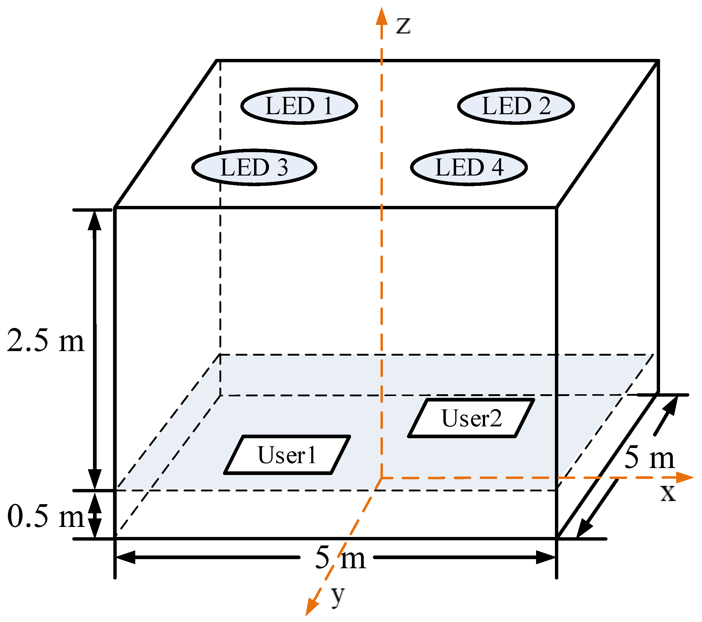
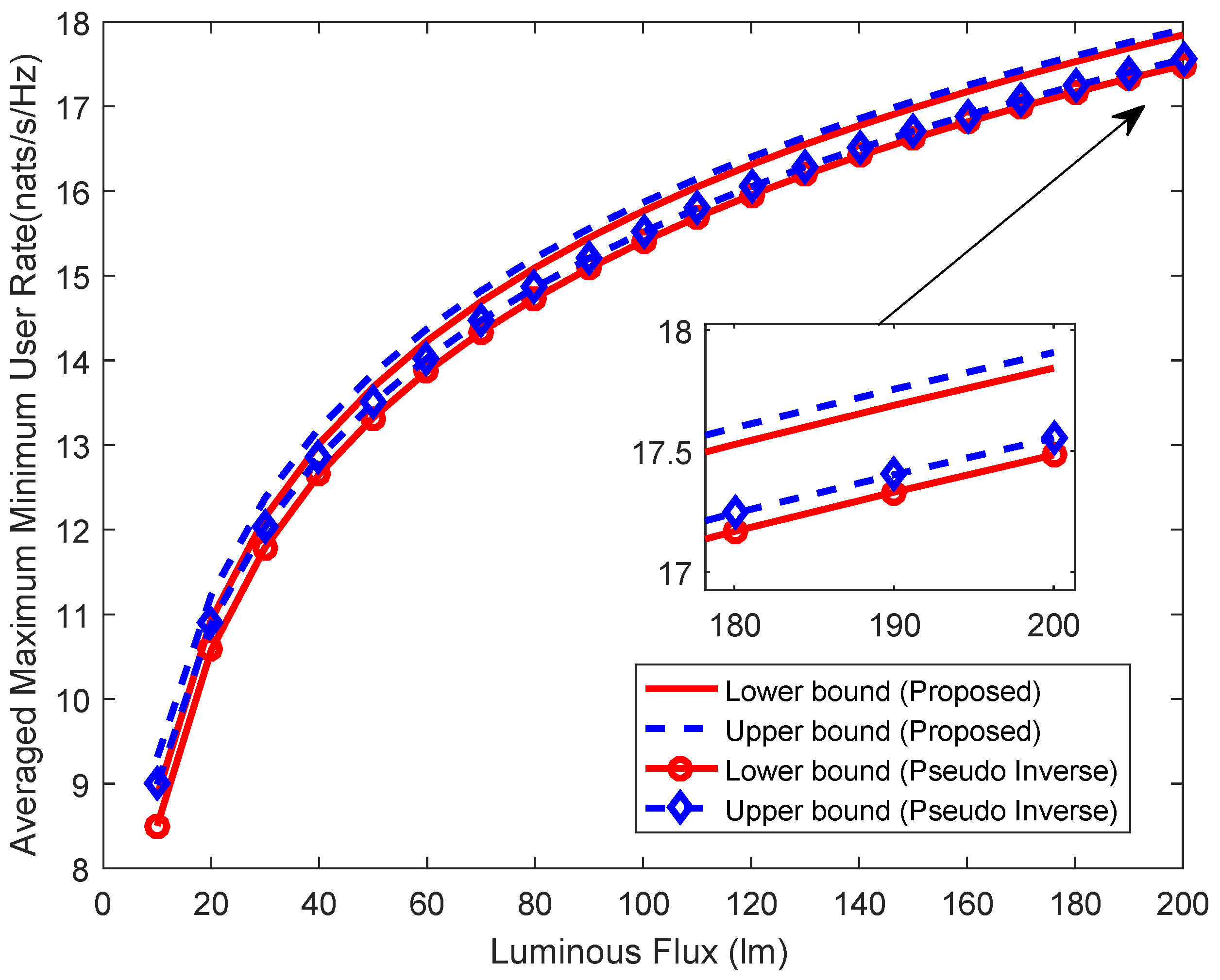
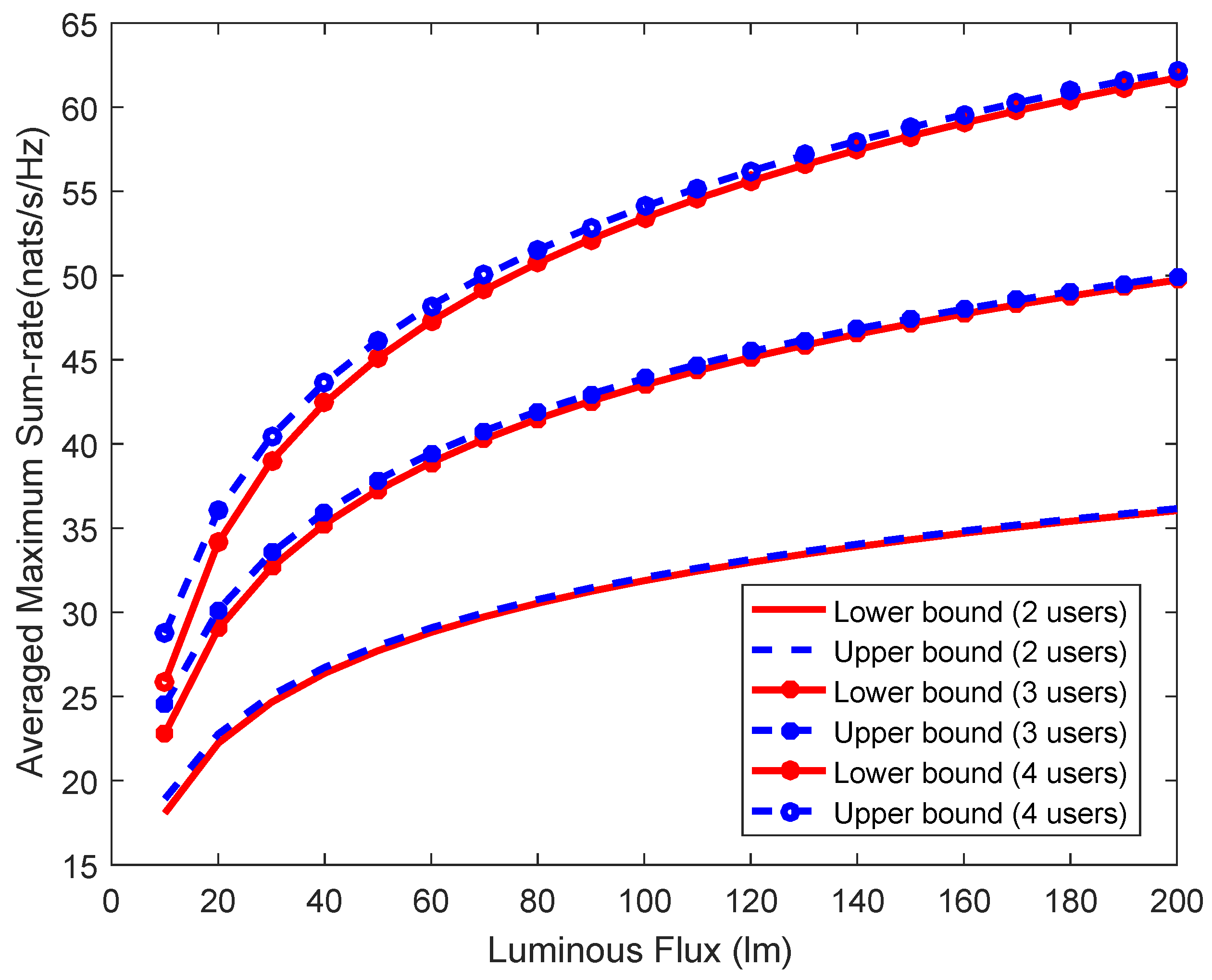
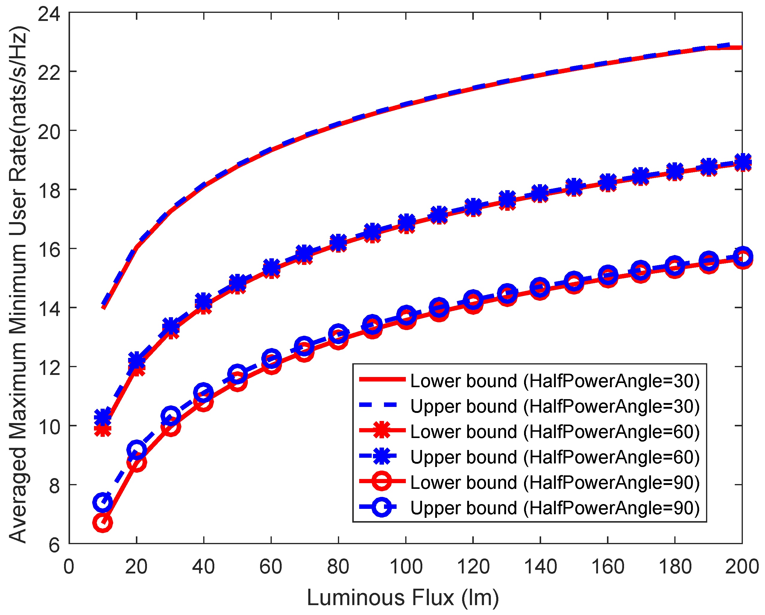
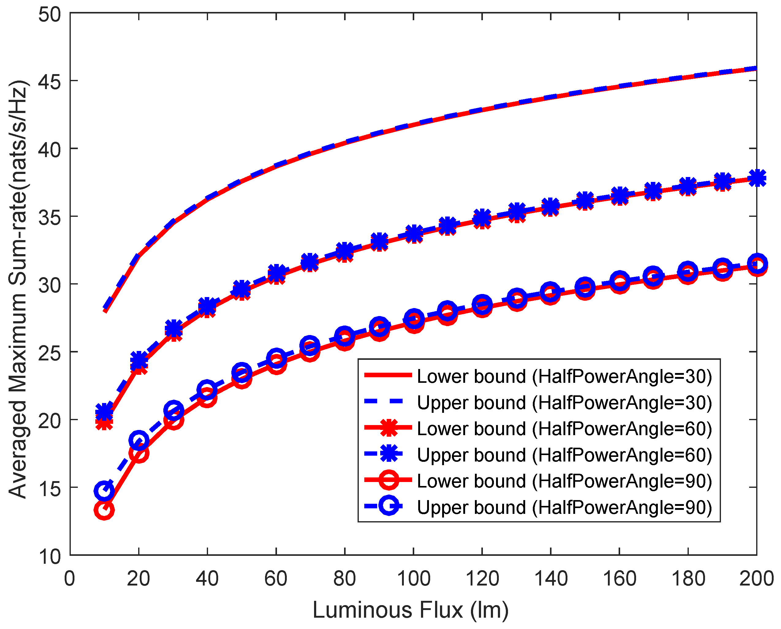
5. Simulation Results

In this section, we present comprehensive simulation results to illustrate the theoretical analyses of the max-min fairness and the maximum sum-rate performances. Figure 3 shows the geometrical configuration of the considered multi-color multi-user VLC system, which consists of 4 RGB LEDs (Cree Xlamp MC-E). Each LED consist of three LED chips which employ red/green/blue lights to transmit information individually. The length, width, and height of the room is respectively 5 m, 5 m, and 3 m. For convenience, a Cartesian coordinate system whose the origin is the center of the floor is used for specifying the positions of users and the LEDs. The noise power spectral density is set to be 1.2 × 10 21   A 2 / Hz which is within an order of magnitude specified in [59]. In addition, we assume that the same modulation bandwidth of 15 MHz for all colors. The total luminous flux ranges from 10 lm to 200 lm [41]. Three CCT values are used in simulations according to ANSI C78.377–2008 [60]. They are 2700 K, 4000 K (Cool White), and 6500 K (Day-light), whose chromaticity coordinates are [0.459, 0.412], [0.380, 0.380], and [0.313, 0.337], respectively. Other parameters used in the simulation are listed in Table 1. Furthermore, all analytical results are obtained by averaging 1000 different positions of users are uniformly placed on the receive plane which is 0.5 m above the floor.
In Figure 4 and Figure 5, we firstly compare our precoding design with the pseudo inverse, which is the optimum precoder under the total average power constraint in RF systems [26]. In the comparisons, both the max-min fairness and the maximum sum-rate are considered when the CCT value is set as 6500 K. The number of uses is 2 and Φ 1 / 2 = 60 . Firstly, we can see that the upper bound and the lower bound in each group asymptotically converge at high luminous flux. This is consistent with that the lower bound in (28) and the upper bound in (29) asymptotically converge at high value of H l F l [35], which help prove the valuableness of the sub-optimal solution in terms of the simulation results. Based on above analysis, we have revised the paper as follows. Secondly, the proposed precoding design performs better than the pseudo inverse in all cases. The max-min fairness gap between the proposed precoding design and the pseudo inverse is about 0.36 nats/s/Hz at the high luminous flux. And the maximum sum-rate gap between the proposed precoding design and the pseudo inverse is about 0.65 nats/s/Hz.
Figure 6 and Figure 7 presents the max-min fairness and the maximum sum-rate versus the total luminous flux with different CCT values. The number of uses is 2 and Φ 1 / 2 = 60 . It is observed that the convergence of the different bounds derived from (28) and (29) is relevant to the CCT values. Especially at the low luminous flux, the larger CCT value has better convergence effect. What’s more, higher data rate can be achieved with larger CCT value. The max-min fairness gap between the 6500 K and 2700 K is about 1.53 nats/s/Hz at the high luminous flux. The maximum sum-rate gap between the 6500 K and 2700 K is about 3.06 nats/s/Hz.
Figure 8 and Figure 9 presents the max-min fairness and the maximum sum-rate versus the total luminous flux with different numbers of users. The CCT value is set as 6500 K and Φ 1 / 2 = 60 . As in Figure 8, the maximum minimum user rate decreases with increasing of the numbers of users. In Figure 9, we can see that double numbers of users can not double the maximum sum-rate. The reason is the increasing of the numbers of users amplifies the impact of the ICI.
Figure 10 and Figure 11 presents the max-min fairness and the maximum sum-rate versus the total luminous flux with different semi-angles at half power. The CCT value is set as 6500 K and the number of uses is 2. Here, we use the semi-angle at half power to describe the overlapping degree of transmitters. The simulation results show that the semi-angle at half power has a significant impact on both the max-min fairness and the maximum sum-rate. The max-min fairness gap between the Φ 1 / 2 = 30 and Φ 1 / 2 = 90 is about 7.21 nats/s/Hz at the high luminous flux. The maximum sum-rate gap between the Φ 1 / 2 = 30 and Φ 1 / 2 = 90 is about 14.43 nats/s/Hz.

6. Conclusions

In this paper, we have studied the optimal linear precoding designs for the multi-color multi-user VLC system. Unlike previous studies, optimal linear precoding designs have been designed in accordance with specific lighting quality constraints and specific system model, which are different from precoding designs for the single-color VLC system. Because of the non-convexity of the optimization problems, slack variables and CCCP have been studied and corresponding algorithms have been developed to find optimal solutions. Various simulation results have been presented to verify the proposed optimal algorithms. The performance with respect to CCT value, number of users and semi-angle at half power have shown the importance of these factors in precoding designs of multi-color multi-user VLC systems. It has been shown in the simulation experiments that the proposed precoding scheme outperforms the conventional pseudo inverse method.

Author Contributions

Conceptualization, H.-Y.Y. and Y.-J.Z.; Methodology, H.-Y.Y. and Y.-J.Z.; Software, D.-F.Z.; Validation, D.-F.Z., H.-Y.Y., Y.-J.Z. and Z.-G.S.; Formal Analysis, D.-F.Z.; Investigation, D.-F.Z. and Z.-G.S.; Resources, H.-Y.Y. and Y.-J.Z.; Data Curation, D.-F.Z. and Z.-G.S.; Writing-Original Draft Preparation, D.-F.Z.; Writing-Review & Editing, H.-Y.Y., Y.-J.Z. and Z.-G.S.; Visualization, D.-F.Z.; Supervision, H.-Y.Y.; Project Administration, H.-Y.Y. and Y.-J.Z.; Funding Acquisition, H.-Y.Y. and Y.-J.Z.

Funding

This research was sponsored in part by Grant No. 61671477 from China NSFC, and in part by Grant No. 2015B010112001 from Major Scientific and Technological Project of Guangdong Province, China.

Conflicts of Interest

The authors declare no conflict of interest.

References

  1. Komine, T.; Nakagawa, M. Fundamental analysis for visible-light communication system using LED lights. IEEE Trans. Consum. Electron. 2004, 50, 100–107. [Google Scholar] [CrossRef]
  2. Elgala, H.; Mesleh, R.; Haas, H. Indoor optical wireless communication: Potential and state-of-the-art. IEEE Commun. Mag. 2011, 49, 56–62. [Google Scholar] [CrossRef]
  3. Nuwanpriya, A.; Ho, S.; Chen, C.S. Indoor MIMO Visible Light Communications: Novel Angle Diversity Receivers for Mobile Users. IEEE J. Sel. Areas Commun. 2015, 33, 1780–1792. [Google Scholar] [CrossRef]
  4. Pathak, P.H.; Feng, X.; Hu, P.; Mohapatra, P. Visible Light Communication, Networking, and Sensing: A Survey, Potential and Challenges. IEEE Commun. Surv. Tutor. 2015, 17, 2047–2077. [Google Scholar] [CrossRef]
  5. Jovicic, A.; Li, J.; Richardson, T. Visible light communication: Opportunities, challenges and the path to market. IEEE Commun. Mag. 2013, 51, 26–32. [Google Scholar] [CrossRef]
  6. Boucouvalas, A.C.; Chatzimisios, P.; Ghassemlooy, Z.; Uysal, M.; Yiannopoulos, K. Standards for indoor Optical Wireless Communications. IEEE Commun. Mag. 2015, 53, 24–31. [Google Scholar] [CrossRef]
  7. Masini, B.M.; Bazzi, A.; Zanella, A. Vehicular Visible Light Networks for Urban Mobile Crowd Sensing. Sensors 2018, 18, 1177. [Google Scholar] [CrossRef] [PubMed]
  8. Feng, L.; Hu, R.Q.; Wang, J.; Xu, P.; Qian, Y. Applying VLC in 5G Networks: Architectures and Key Technologies. IEEE Netw. 2016, 30, 77–83. [Google Scholar] [CrossRef]
  9. Zeng, Z.; Fu, S.; Zhang, H.; Dong, Y.; Cheng, J. A survey of underwater optical wireless communications. IEEE Commun. Surv. Tutor. 2017, 19, 204–238. [Google Scholar] [CrossRef]
  10. Akhoundi, F.; Salehi, J.A.; Tashakori, A. Cellular underwater wireless optical CDMA network: Performance analysis and implementation concepts. IEEE Trans. Commun. 2015, 63, 882–891. [Google Scholar] [CrossRef]
  11. Steigerwald, D.A.; Bhat, J.C.; Collins, D.; Fletcher, R.M.; Holcomb, M.O.; Ludowise, M.J.; Martin, P.S.; Rudaz, S.L. Illumination with solid state lighting technology. IEEE J. Sel. Top. Quantum Electron. 2002, 8, 310–320. [Google Scholar] [CrossRef]
  12. Grubor, J.; Randel, S.; Langer, K.; Walewski, J.W. Broadband Information Broadcasting Using LED-Based Interior Lighting. J. Lightw. Technol. 2008, 26, 3883–3892. [Google Scholar] [CrossRef]
  13. Karunatilaka, D.; Zafar, F.; Kalavally, V.; Parthiban, R. LED Based Indoor Visible Light Communications: State of the Art. IEEE Commun. Surv. Tutor. 2015, 17, 1649–1678. [Google Scholar] [CrossRef]
  14. Wang, Y.; Huang, X.; Tao, L.; Shi, J.; Chi, N. 4.5-Gb/s RGB-LED based WDM visible light communication system employing CAP modulation and RLS based adaptive equalization. Opt. Express 2015, 23, 13626–13633. [Google Scholar] [CrossRef] [PubMed]
  15. Cossu, G.; Ali, W.; Corsini, R.; Ciaramella, E. Gigabit-class optical wireless communication system at indoor distances (1.5/4 m). Opt. Express 2015, 23, 15700–15705. [Google Scholar] [CrossRef] [PubMed]
  16. Wang, Y.; Tao, L.; Huang, X.; Shi, J.; Chi, N. 8-Gb/s RGBY LED-Based WDM VLC System Employing High-Order CAP Modulation and Hybrid Post Equalizer. IEEE Photonics J. 2015, 7, 1–7. [Google Scholar] [CrossRef] [Green Version]
  17. Das, P.; Park, Y.; Kim, K.D. Performance of color-independent OFDM visible light communication based on color space. Opt. Commun. 2014, 324, 264–268. [Google Scholar] [CrossRef]
  18. Bykhovsky, D.; Arnon, S. OFDM Allocation Optimization for Crosstalk Mitigation in Multiple Free-Space Optical Interconnection Links. J. Lightw. Technol. 2015, 33, 2777–2783. [Google Scholar] [CrossRef]
  19. Zeng, L.; O’Brien, D.C.; Minh, H.L.; Faulkner, G.E.; Lee, K.; Jung, D.; Oh, Y.; Won, E.T. High data rate multiple input multiple output (MIMO) optical wireless communications using white led lighting. IEEE J. Sel. Areas Commun. 2009, 27, 1654–1662. [Google Scholar] [CrossRef]
  20. Fath, T.; Haas, H. Performance Comparison of MIMO Techniques for Optical Wireless Communications in Indoor Environments. IEEE Trans. Commun. 2013, 61, 733–742. [Google Scholar] [CrossRef] [Green Version]
  21. Wu, L.; Zhang, Z.; Liu, H. MIMO-OFDM visible light communications system with low complexity. In Proceedings of the 2013 IEEE International Conference on Communications (ICC), Budapest, Hungary, 9–13 June 2013; pp. 3933–3937. [Google Scholar] [CrossRef]
  22. Burton, A.; Minh, H.L.; Ghassemlooy, Z.; Bentley, E.; Botella, C. Experimental Demonstration of 50-Mb/s Visible Light Communications Using 4 × 4 MIMO. IEEE Photonics Technol. Lett. 2014, 26, 945–948. [Google Scholar] [CrossRef]
  23. Azhar, A.H.; Tran, T.; O’Brien, D. A Gigabit/s Indoor Wireless Transmission Using MIMO-OFDM Visible-Light Communications. IEEE Photonics Technol. Lett. 2013, 25, 171–174. [Google Scholar] [CrossRef]
  24. Ying, K.; Qian, H.; Baxley, R.J.; Zhou, G.T. MIMO Transceiver Design in Dynamic-Range-Limited VLC Systems. IEEE Photonics Technol. Lett. 2016, 28, 2593–2596. [Google Scholar] [CrossRef]
  25. Ying, K.; Qian, H.; Baxley, R.J.; Yao, S. Joint Optimization of Precoder and Equalizer in MIMO VLC Systems. IEEE J. Sel. Areas Commun. 2015, 33, 1949–1958. [Google Scholar] [CrossRef]
  26. Wiesel, A.; Eldar, Y.C.; Shamai, S. Zero-Forcing Precoding and Generalized Inverses. IEEE Trans. Signal Process. 2008, 56, 4409–4418. [Google Scholar] [CrossRef] [Green Version]
  27. Spencer, Q.H.; Swindlehurst, A.L.; Haardt, M. Zero-forcing methods for downlink spatial multiplexing in multiuser MIMO channels. IEEE Trans. Signal Process. 2004, 52, 461–471. [Google Scholar] [CrossRef]
  28. Peel, C.B.; Hochwald, B.M.; Swindlehurst, A.L. A vector-perturbation technique for near-capacity multiantenna multiuser communication-part I: Channel inversion and regularization. IEEE Trans. Commun. 2005, 53, 195–202. [Google Scholar] [CrossRef]
  29. Stankovic, V.; Haardt, M. Generalized Design of Multi-User MIMO Precoding Matrices. IEEE Trans. Wirel. Commun. 2008, 7, 953–961. [Google Scholar] [CrossRef]
  30. Hong, Y.; Chen, J.; Wang, Z.; Yu, C. Performance of a Precoding MIMO System for Decentralized Multiuser Indoor Visible Light Communications. IEEE Photonics J. 2013, 5, 7800211. [Google Scholar] [CrossRef]
  31. Chen, J.; Ma, N.; Hong, Y.; Yu, C. On the performance of MU-MIMO indoor visible light communication system based on THP algorithm. In Proceedings of the 2014 IEEE/CIC International Conference on Communications in China (ICCC), Shanghai, China, 13–15 October 2014; pp. 136–140. [Google Scholar] [CrossRef]
  32. Pham, T.V.; Minh, H.L.; Ghassemlooy, Z.; Hayashi, T.; Pham, A.T. Sum-rate maximization of multi-user MIMO visible light communications. In Proceedings of the 2015 IEEE International Conference on Communication Workshop (ICCW), London, UK, 8–12 June 2015; pp. 1344–1349. [Google Scholar] [CrossRef]
  33. Ma, H.; Lampe, L.; Hranilovic, S. Coordinated Broadcasting for Multiuser Indoor Visible Light Communication Systems. IEEE Trans. Commun. 2015, 63, 3313–3324. [Google Scholar] [CrossRef]
  34. Li, B.; Wang, J.; Zhang, R.; Shen, H.; Zhao, C.; Hanzo, L. Multiuser MISO Transceiver Design for Indoor Downlink Visible Light Communication Under Per-LED Optical Power Constraints. IEEE Photonics J. 2015, 7, 1–15. [Google Scholar] [CrossRef]
  35. Pham, T.V.; Le-Minh, H.; Pham, A.T. Multi-User Visible Light Communication Broadcast Channels with Zero-Forcing Precoding. IEEE Trans. Commun. 2017, 65, 2509–2521. [Google Scholar] [CrossRef]
  36. Gong, C.; Li, S.; Gao, Q.; Xu, Z. Power and Rate Optimization for Visible Light Communication System With Lighting Constraints. IEEE Trans. Signal Process. 2015, 63, 4245–4256. [Google Scholar] [CrossRef]
  37. Karunatilaka, D.; Kalavally, V.; Parthiban, R. Improving Lighting Quality and Capacity of OFDM-Based WDM-VLC Systems. IEEE Photonics Technol. Lett. 2016, 28, 2149–2152. [Google Scholar] [CrossRef]
  38. Wang, R.; Gao, Q.; You, J.; Liu, E.; Wang, P.; Xu, Z.; Hua, Y. Linear Transceiver Designs for MIMO Indoor Visible Light Communications Under Lighting Constraints. IEEE Trans. Commun. 2017, 65, 2494–2508. [Google Scholar] [CrossRef]
  39. Monteiro, E.; Hranilovic, S. Design and Implementation of Color-Shift Keying for Visible Light Communications. J. Lightw. Technol. 2014, 32, 2053–2060. [Google Scholar] [CrossRef] [Green Version]
  40. Macadam, D.L. Visual sensitivities to color differences in daylight. J. Opt. Soc. Am. 1942, 32, 247–274. [Google Scholar] [CrossRef]
  41. Jiang, R.; Wang, Z.; Wang, Q.; Dai, L. Multi-User Sum-Rate Optimization for Visible Light Communications With Lighting Constraints. J. Lightw. Technol. 2016, 34, 3943–3952. [Google Scholar] [CrossRef]
  42. Dong, J.; Zhang, Y.; Zhu, Y. Convex relaxation for illumination control of multi-color multiple-input-multiple-output visible light communications with linear minimum mean square error detection. Appl. Opt. 2017, 56, 6587–6595. [Google Scholar] [CrossRef] [PubMed]
  43. Grant, M.; SP, B. CVX: MATLAB Software for Disciplined Convex Programming. 2014. Available online: http://cvxr.com/cvx/ (accessed on 1 October 2018).
  44. Gao, Q.; Wang, R.; Xu, Z.; Hua, Y. DC-Informative Joint Color-Frequency Modulation for Visible Light Communications. J. Lightw. Technol. 2015, 33, 2181–2188. [Google Scholar] [CrossRef] [Green Version]
  45. Wyszecki, G.; Stiles, W.S. Color Science; Wiley: New York, NY, USA, 1982; Volume 8. [Google Scholar]
  46. Pham, Q.; Hwang, W. α-Fair resource allocation in non-orthogonal multiple access systems. IET Commun. 2018, 12, 179–183. [Google Scholar] [CrossRef]
  47. Guo, C.; Zhang, Y.; Sheng, M.; Wang, X.; Li, Y. α-Fair Power Allocation in Spectrum-Sharing Networks. IEEE Trans. Veh. Technol. 2016, 65, 3771–3777. [Google Scholar] [CrossRef]
  48. Pham, Q.; Hwang, W. Fairness-Aware Spectral and Energy Efficiency in Spectrum-Sharing Wireless Networks. IEEE Trans. Veh. Technol. 2017, 66, 10207–10219. [Google Scholar] [CrossRef]
  49. Lan, T.; Kao, D.; Chiang, M.; Sabharwal, A. An Axiomatic Theory of Fairness in Network Resource Allocation. In Proceedings of the 2010 Proceedings IEEE INFOCOM, San Diego, CA, USA, 14–19 March 2010; pp. 1–9. [Google Scholar] [CrossRef]
  50. Zabini, F.; Bazzi, A.; Masini, B.M.; Verdone, R. Optimal Performance Versus Fairness Tradeoff for Resource Allocation in Wireless Systems. IEEE Trans. Wirel. Commun. 2017, 16, 2587–2600. [Google Scholar] [CrossRef]
  51. Zabini, F.; Bazzi, A.; Masini, B.M. Throughput versus fairness tradeoff analysis. In Proceedings of the 2013 IEEE International Conference on Communications (ICC), Budapest, Hungary, 9–13 June 2013; pp. 5131–5136. [Google Scholar] [CrossRef]
  52. Luo, Z.; Zhang, S. Dynamic Spectrum Management: Complexity and Duality. IEEE J. Sel. Top. Quantum Electron. 2008, 2, 57–73. [Google Scholar] [CrossRef]
  53. Lapidoth, A.; Moser, S.M.; Wigger, M.A. On the Capacity of Free-Space Optical Intensity Channels. IEEE Trans. Inf. Theory 2009, 55, 4449–4461. [Google Scholar] [CrossRef] [Green Version]
  54. Shannon, C.E. A mathematical theory of communication. Bell Syst. Tech. J. 1948, 27, 379–423. [Google Scholar] [CrossRef]
  55. Cover, T.M.; Thomas, J.A. Elements of Information Theory; Wiley: Hoboken, NJ, USA; Tsinghua University Press: Beijing, China, 1991; pp. 155–183. [Google Scholar]
  56. Chaaban, A.; Morvan, J.; Alouini, M. Free-Space Optical Communications: Capacity Bounds, Approximations, and a New Sphere-Packing Perspective. IEEE Trans. Commun. 2016, 64, 1176–1191. [Google Scholar] [CrossRef]
  57. Yuille, A.L.; Rangarajan, A. The Concave-Convex Procedure. Neural Comput. 2003, 15, 915–936. [Google Scholar] [CrossRef] [PubMed]
  58. Sriperumbudur, B.K.; Lanckriet, G.R.G. On the convergence of the concave-convex procedure. In Proceedings of the 22nd International Conference on Neural Information Processing Systems, Vancouver, BC, Canada, 7–10 December 2009; pp. 1759–1767. [Google Scholar]
  59. Grubor, J.; Jamett, O.C.G.; Walewski, J.W.; Randel, S.; Langer, K.D. High-Speed Wireless Indoor Communication via Visible Light; Itg-Fachbericht Breitbandversorgung in Deutschland—Vielfalt Fur Alle; VDE Verlag: Berlin, Germany, 2007. [Google Scholar]
  60. American National Standards Institute. C78. 376-2001: Specifications for the Chromaticity of Fluorescent Lamps; ANSI: Washington, DC, USA, 2001. [Google Scholar]
Figure 1. Schematic diagram of channel model.
Crystals 08 00404 g001
Figure 2. Schematic diagram of precoding model.
Crystals 08 00404 g002
Figure 3. Geometrical configuration of multi-color multi-user visible light communication (VLC) system.
Crystals 08 00404 g003
Figure 4. Max-min fairness comparison between the proposed precoding design and the pseudo inverse method.
Crystals 08 00404 g004
Figure 5. Maximum sum-rate comparison between the proposed precoding design and the pseudo inverse method.
Crystals 08 00404 g005
Figure 6. Max-min fairness with different correlated color temperature (CCT) values.
Crystals 08 00404 g006
Figure 7. Maximum sum-rate with different CCT values.
Crystals 08 00404 g007
Figure 8. Max-min fairness with different numbers of users.
Crystals 08 00404 g008
Figure 9. Maximum sum-rate with different numbers of users.
Crystals 08 00404 g009
Figure 10. Max-min fairness with different semi-angle at half power.
Crystals 08 00404 g010
Figure 11. Maximum sum-rate with different semi-angle at half power.
Crystals 08 00404 g011
Table 1. Parameter Setup.
ParameterValue
Transmitter parameters
Type of white LEDLED RGB LED
(Cree Xlamp MC-E)
LED positionsLED 1: 2 , 2 , 3
LED 2: 2 , 2 , 3
LED 3: 2 , 2 , 3
LED 4: 2 , 2 , 3
Maximum forward current I M A X 700 mA
Chromaticity coordinate of each chipRed: (0.7006, 0.2993)
Green: (0.1547, 0.8059)
Blue: (0.1440, 0.0297)
Luminance flux - Forward current conversion coefficient for each chipRed: 0.0114 A/lm
Green: 0.0052 A/lm
Blue: 0.0427 A/lm
Receiver parameters
Interference ratio ϵ 0.1
PD physical area A P D 1 cm 2
Receiving FOV Ψ F 60
Receiver responsivity μ c 0.4 A / W

