Article

Chemical and Phase Reactions on the Contact between Refractory Materials and Slags, a Case from the 19th Century Zn-Pb Smelter in Ruda Śląska, Poland

1
Institute of Earth Sciences, Faculty of Natural Sciences, University of Silesia, Będzińska 60, 41-200 Sosnowiec, Poland
2
Institute of Materials Engineering, and Silesian Center for Education and Interdisciplinary Research, University of Silesia in Katowice, 75 Pulku Piechoty 1A, 41-500 Chorzow, Poland
*
Author to whom correspondence should be addressed.
Minerals 2020, 10(11), 1006; https://doi.org/10.3390/min10111006
Submission received: 6 October 2020 / Revised: 8 November 2020 / Accepted: 10 November 2020 / Published: 12 November 2020
(This article belongs to the Special Issue Mineralogy, Trace Elements and Isotopic Tracers in Archaeometallurgy)

Abstract

:
Slags from the historic metallurgy of Zn-Pb ores are known for unique chemical and phase compositions. The oxides, silicates, aluminosilicates, and amorphous phases present therein often contain in the structure elements that are rare in natural conditions, such as Zn, Pb, As. The study focuses on processes occurring on the contact of the melted batch and the refractory materials that build the furnace, which lead to the formation of these phases. To describe them, chemical (X-ray fluorescence (XRF), inductively coupled plasma mass spectrometry (ICP-MS)) and petrological ((X-ray diffraction (XRD), electron probe micro-analyses (EPMA), Raman spectroscopy) analyses were performed on refractory material, slag, and contact of both. Two main types of reactions have been distinguished: gas/fluid- refractories and liquid- refractories. The first of them enrich the refractories with elements that migrate with the gas (Pb, K, Na, As, Zn) and transport the components building it (Fe, Mg, Ca) inward. Reactions between melted batch and refractory materials through gravitational differentiation and the melting of refractories lead to the formation of an aluminosilicate liquid with a high content of heavy elements. Cooling of this melt causes crystallization of minerals characteristic for slag, but with a modified composition, such as Fe-rich pyroxenes, Pb-rich K-feldspar, or PbO-As2O3-SiO2 glass.

1. Introduction

One of the characteristic features of the Upper Silesia landscape is the presence of metallurgical waste dumps. These landfills are associated with a centuries-old history of smelting silver, lead, and zinc. The exploitation and processing of the ores in Silesia-Cracow region were carried out from the Mississippi Valley (MTV) type deposits [1]. Metallurgical activity in this region dates back to at least the 12th century, however, it can be assumed that primitive mining and related metallurgy had occurred much earlier [1]. In the past, waste generated during metal production was mostly transported and left in landfills. Due to the high content of heavy metals and other harmful elements, slag research mainly focuses on their impact on the environment [2,3,4,5,6,7,8,9,10,11,12,13,14]. Such studies are especially important due to the fact that currently, to reduce the amount of deposited slag, they are increasingly used by local enterprises [2,13]. Slag is most often used in the construction of local roads and the production of cement, concrete [3,4,5,9,15,16,17,18], and hydrotechnical constructions [19]. Metallurgical waste landfills may also be used to recover metals contained therein. Live organisms (such as fungi, bacteria) can be used for this purpose [20,21,22]. Recently, slags have been used as the tool for recreating historic metal smelting methods [23,24,25,26,27,28]. Both in Poland and in the world, smelting temperature, type of oxidation-reduction conditions used in the metallurgical process, composition and amount of additives affecting production efficiency, and silicate melt properties (e.g., viscosity) were determined based on slags [24,25,28,29,30,31,32,33,34]. Slags phase composition and chemistry are also studied due to the unusual crystallization environment [3,17,34,35]. The uniqueness of this environment lies mainly in the crystallization of phases at undercooling conditions [24,30,35] and the presence of unique elements in the silicates, oxides, and glass phases [3]. The degree of undercooling has a significant effect on the order, differentiation [24], and the habit of crystallizing slag phases [24,35]. Little is known about the ion diffusion between the melt and refractory materials and the formation of interaction zones between the melt and refractories. Existing studies [36] focus on the different types of refractory materials (made of MgAl2O4) and metal smelted (copper). Numerous studies [12,33,37,38] mention the occurrence of unique phases, mostly concentrating Potentially Toxic Elements (PTEs), within Zn-Pb slags, but none of them describes the reaction leading to their creation. In this study, we aim to describe such reactions related to the 19th century smelting process of zinc. Results shown in this study give new insight into the already recreated smelting process [27], explain the reactions leading to the formation of unique phases within slags, e.g., SiO2-PbO-As2O3 glass, and suggest the environmental significance of the occurrence of slags with elements of refractory materials.

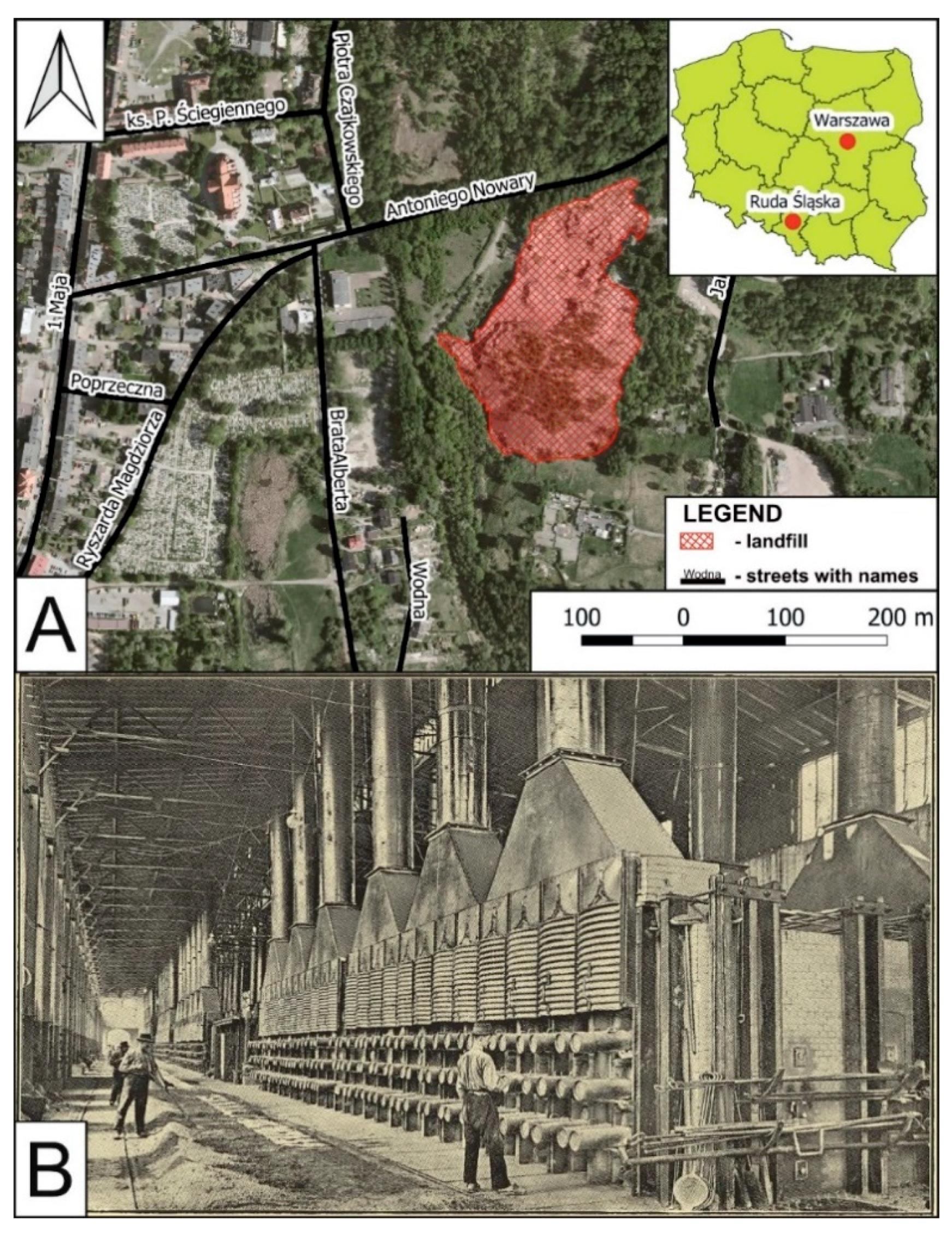
2. Location and Historical Smelting Process

Studied slag samples were collected at the metallurgical waste landfill located in Ruda Śląska, Silesian Voivodeship, Poland (Figure 1A). The investigated landfill is related to the activities of the “Hugo” zinc smelter, which operated in the years 1812–1932 [39]. The landfill is located less than 100 m from inhabited areas.
In the case of 19th century zinc smelters in Upper Silesia, the so-called Silesian method of zinc smelting was widely used. It was a method developed by J.C. Ruberg around 1800 in the glassworks in Wesoła village located near Mysłowice city. Detailed documentation describing this process did not remain. However, it is known that calamine and sulfide ores were used and the production process was divided into several stages [27,41,42,43]: the ore enrichment, roasting, mixing with additives, smelting, and further processing (casting, rolling, etc.). For sulfide ores, the roasting process was crucial due to the necessity to oxidize the ore minerals and remove sulfur [27,43]. Then, the ores prepared in this way were mixed with coal (in later periods with coke) [41], fluxes, and placed with the help of shovels in horizontally arranged muffles (retorts) made of refractory clay (Figure 1B) [43,44]. Muffles lay flat within the continuously heated furnace. A zinc vapor condenser was tightly attached to each retort. The use of this type of furnace enabled the continuous operation of the smelter without cooling the entire system [43]. According to modern research, smelting temperatures at the Ruda Śląska site were within 1063–1261 °C [34]. The addition of coal to the batch resulted in reducing conditions.

3. Materials and Methods

3.1. Sampling

Slags containing elements of refractories occurred in the landfill when the worn muffles and furnace linings were replaced, or when these were damaged in the smelting process. The layers that are rich in refractive materials alternate with the typical glassy slag characteristic for this location [12,35]. To recreate the reactions on the contact between the refractories and slag melt, it was crucial to collect the material containing these elements, and the material should not show signs of weathering. The weathering process could lead to the leaching of some elements from both refractories and slags, influencing performed analyses. After careful investigations, five samples without signs of weathering or secondary mineralization (Figure 2) were selected from previous studies [12,35]. This was possible due to the collection of samples from the fresh exposure of the landfill wall after part of the dump was exploited for commercial purposes.

3.2. Phase Composition and Chemistry of Phases

3.2.1. Microscopic Observations, SEM-EDS and EPMA

Thin sections of samples were examined using an Olympus BX-51 optical microscope and scanning electron microscope (SEM; Thermo Scientific Phenom XL Desktop), equipped with an energy-dispersive spectrometer (EDS) at the Faculty of Natural Sciences, University of Silesia. Electron probe micro-analyses (EPMA) were performed using a CAMECA SX 100 electron microprobe (Inter-Institutional Laboratory of Microanalysis of Minerals and Synthetic Materials, University of Warsaw). Analyses were performed at 15 keV accelerating voltage, a 10–20.1 nA beam current, and a beam diameter of up to 5 μm. Standards used during EPMA analyses are shown in Table 1.

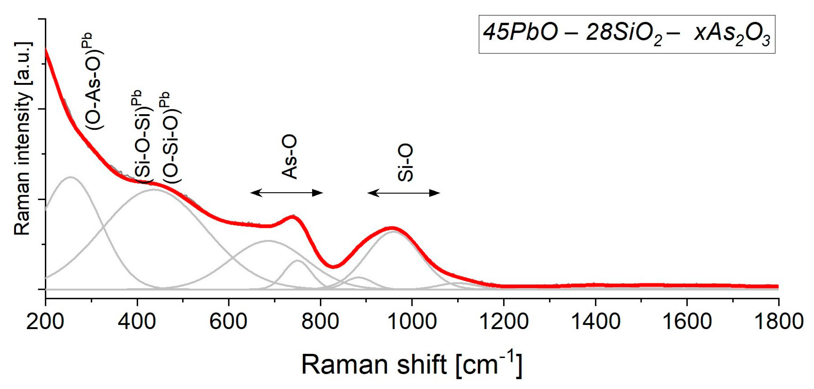
3.2.2. Raman Spectroscopy

Raman measurements were carried out using a WITec alpha 300 R system equipped with a solid-state laser (λ = 488 nm) and a high sensitivity back-illuminated CCD camera at the Faculty of Natural Sciences, University of Silesia. The excitation laser radiation was coupled into a microscope through a single-mode optical fiber with a 50 μm diameter. An air Olympus MPlan (100×/0.90 na) objective was used during the experiment. Raman-scattered light was focused on multi-mode fiber (100 μm diameter). A grating with a 600 line/mm was applied. Spectra were collected in the 200–1800 cm−1 range, wherein each accumulated by 20 scans, the integration time of 10 s, and a resolution of 3 cm−1. The low-frequency range below 200 cm−1 was luminescence-affected and it was not taken into account during further interpretation. The spectrometers’ monochromator was calibrated using the Raman scattering line of a silicon plate (520.7 cm−1). All data were manipulated in the post-processing approach by performing a baseline correction, cosmic ray removal, and peak fitting analysis in GRAMS 9.2 Software Package.

3.2.3. X-ray Diffraction

Two samples, best representing the uncontaminated refractory material, and slag were selected for chemical analysis and XRD. X-ray powder diffraction data were obtained using a PANalytical X’PERT PRO-PW 3040/60 diffractometer (CoKα1 source radiation, Fe-filter to reduce the Kβ radiation, and X’Celerator detector), at the Faculty of Natural Sciences, University of Silesia. The analysis was performed in the angular range of 5–90° 2θ with a shift step of 0.02° 2θ, the lamp current voltage was 40 kv at 40 mA. Quantitative data processing was performed using the X’PERT High Score Plus software using the PDF4+ database, and applying the Rietveld method. The Rietveld method uses least squares approach to match the theoretical profile line with measured peak intensity of a powder sample, thus minimizing the residual function, and refining the crystal structure of the compound.

3.3. Bulk Chemical Composition

The bulk chemical compositions of the primary slags were analysed at Bureau Veritas Mineral Laboratories by a combination of X-ray fluorescence (XRF) spectrometry and inductively coupled plasma mass spectrometry (ICP-MS) for a broader spectrum of major, minor, and trace elements. Sample preparation consisted of LiBO2 fusion for XRF and lithium tetraborate decomposition and Aqua Regia digestion for ICP-MS. Loss-on-Ignition was determined prior to XRF at 1000 °C. The analytical reproducibility for bulk chemical analyses was estimated from a replicate analysis of slag sample. The uncertainty (2σ) ranges from 0.00% to 0.23% for Fe2O3, relative standard deviation (RSD) ranges from 0% to 47.14% for Cr2O3. Analytical accuracy was calculated with standards OREAS184, SY-3(D), OREAS45E, OREAS25A-4A. Error is within range of 0.0–0.2% for SiO2, while relative error ranges from 0.0% to 7.22% for Sr.

4. Results

4.1. Chemistry

The refractory material consists of SiO2 (65.70 wt.%), Al2O3 (29.08 wt.%), Fe2O3 (2.38 wt.%), TiO2 (0.73 wt.%), K2O (0.59 wt.%), CaO (0.41 wt.%), and MgO (0.30 wt.%) (Table 2). Among the trace elements, the following are distinguished above 100 ppm: Zn (223 ppm), Pb (145 ppm), Zr (113 ppm) (Table 2).
Slags are mainly composed of SiO2 (38.17 wt.%), Fe2O3 (22.71 wt.%), Al2O3 (15.81 wt.%), CaO (10.56 wt.%), MgO (5.73 wt.%), K2O (1.58 wt.%), and MnO (0.41 wt.%) (Table 2). Additionally, the presence of Zn (>1%), Pb (3775 ppm), As (2155 ppm), Sr (590 ppm), Zr (156 ppm), V (141 ppm), Ni (141 ppm) is observed (Table 2).

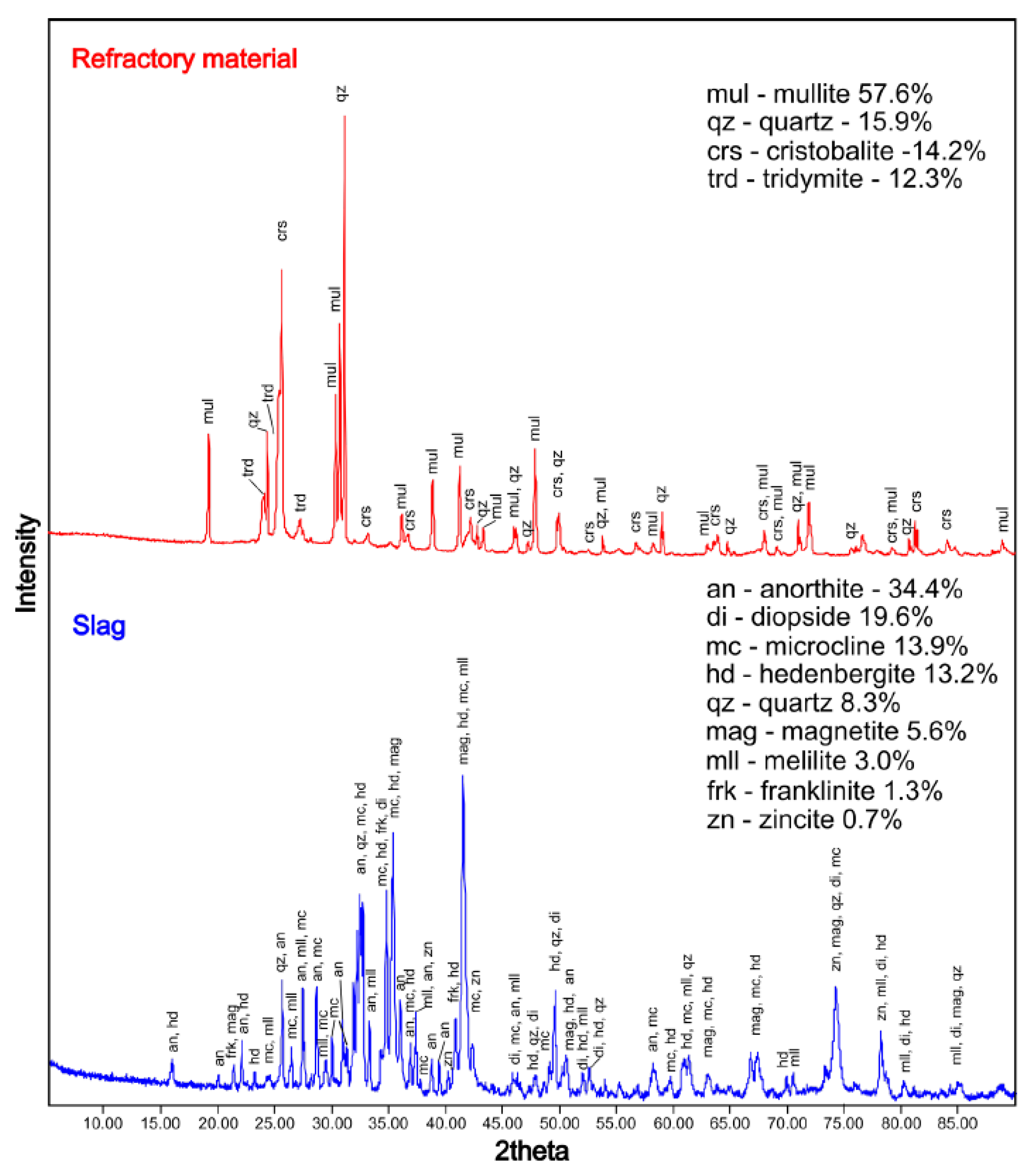
4.2. Phase Composition

Based on the X-ray diffraction data, the refractory materials consist of mullite (3Al2O3·2SiO2) (57.6 vol.%) and SiO2 polymorphs (42.4 vol.%), in the form of quartz (15.9 vol.%), cristobalite (14.2 vol.%), and tridymite (12.3 vol.%) (Figure 3). Slag phase composition is dominated by feldspars with a total content of 48.3 vol.% (Figure 3). Among feldspars, anorthite (CaAl2Si2O8) is the most abundant (34.4 vol.%) (Figure 3). As well as feldspar, pyroxenes (32.8 vol.%) are also distinguished with a cell corresponding to a diopside (CaMg(Si2O6)) (19.6 vol.%) and hedenbergite (CaFe(Si2O6)) (13.2 vol.%). The slag also contains quartz (8.3 vol.%), melilite (3.0 vol.%), and oxide phases (about 7.6 vol.%) (Figure 3). Among oxides, spinels (6.9 vol.%) are most common: magnetite (5.6 vol.%; Fe2+Fe3+2O4), and franklinite (1.3 vol.%; ZnFe2O4). Zincite (ZnO) occurs in the amount of 0.7 vol.% (Figure 3).
According to SEM-EDS and EPMA, refractories are dominated by oxides and silicates (Figure 4A). Oxide phases are represented by quartz and its polymorphs, which occur in the analysed sample in the form of crystals with diameters from several dozen to about 200 μm (Figure 4A). Cracks were often observed in SiO2 crystals (Figure 4A). Silicates occur as mullite. Its crystals are elongated without visible cracks, but with a visible zonal structure. The crystal length reaches up to 100 μm. Mullite also occurs in the form of a fine-grained binder (Figure 4A). Corundum (Al2O3; Table 3), occurs sporadically as small (up to 100 μm long) crystals with an euhedral structure. The lack of peaks corresponding to corundum on the diffractogram (Figure 3) is caused by its low content in the sample.
According to SEM-EDS and EPMA, slags are composed mostly of silicates and oxides. Feldspars, pyroxenes, melilites, and spinels were observed during SEM observations. Feldspars occur in the form of crystals with a diameter from several up to 60 μm (Figure 4B). Pyroxenes and melilites are mainly anhedral, and their size reaches several dozen μm (Figure 4B). Spinels form euhedral crystals with a diameter of up to 15 µm (Figure 4B).
During microscopic observations, the area of impact of the metallurgical melt on the refractory material was visible (Figure 4D). The zone consists of phases characteristic for both of the aforementioned zones, but with different chemical compositions. New phases, which do not occur in unchanged slag or refractories were also found. In the contact zone, the most common phases are pyroxenes, potassium feldspars, SiO2 polymorphs, and glass. Pyroxenes are in the form of crystals up to several hundred µm in length. In the area of melt interaction, feldspars are formed in the form of plates. The size of feldspars ranges from several dozen to several hundred µm. During the EPMA and SEM-EDS analyses, it was found that the feldspars crystallizing from the melt near the refractories are often overgrown with fine anhedral quartz crystals (Figure 4C). The size of SiO2 crystals ranges from a few to a dozen or so μm (Figure 4C). Due to the lack of X-ray structural data in the micro area, it cannot be determined which polymorphs of SiO2 and in what proportions are occurring in this zone. However, taking into account the temperature during smelting, they are most likely high-temperature varieties such as tridymite or cristobalite. Glasses occurring in the studied slags fill the space in between other phases (Figure 4C). Mullite, corundum, and alumohematite ((Fe,Al)2O3) are also present in the contact zone. Mullite forms the small crystals with a diameter up to several μm with a homogeneous structure. Corundum occurs as euhedral crystals up to 100 µm in length. Alumiohematite crystals reach up to 20 μm.

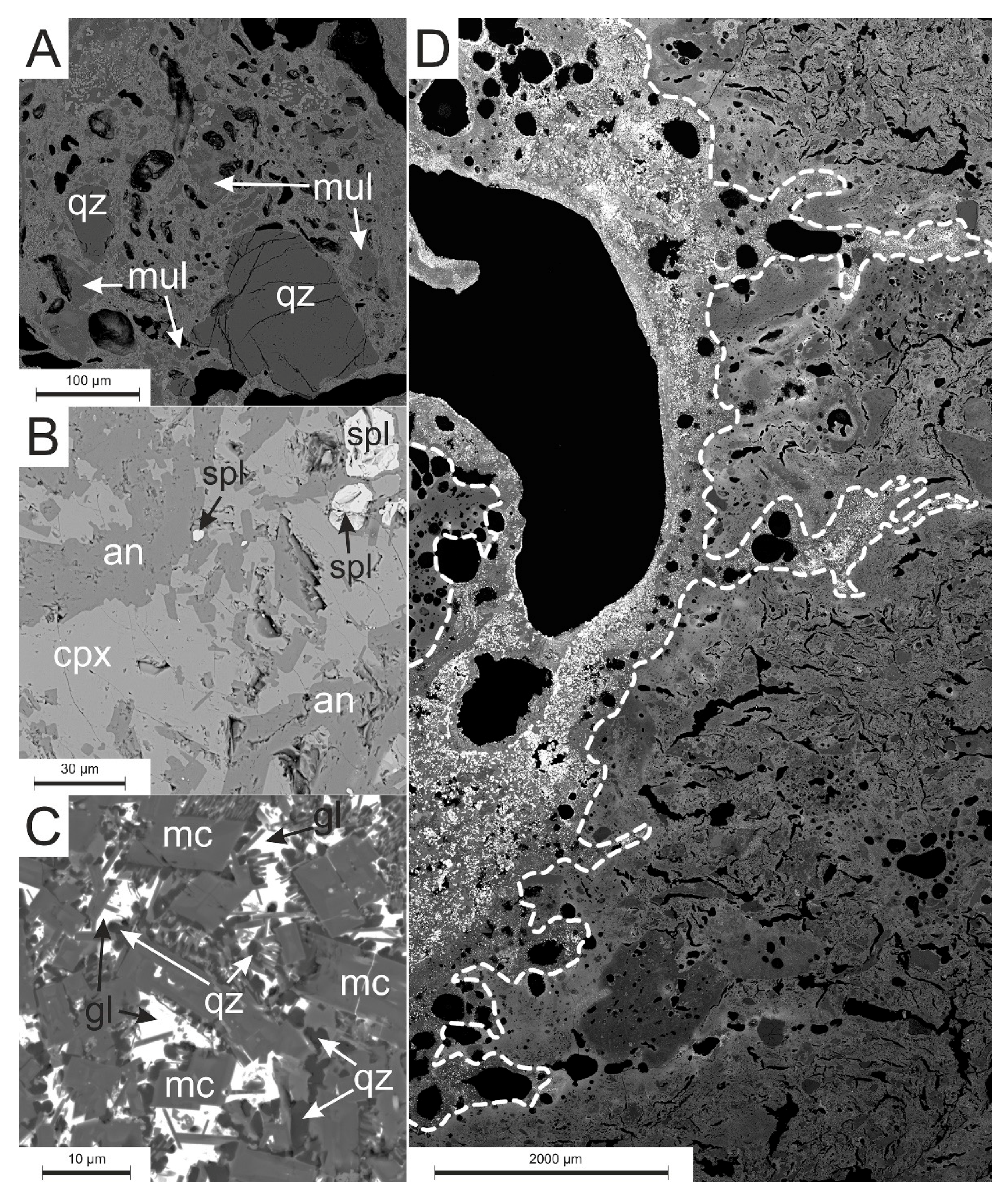
4.3. Chemistry of Phases

4.3.1. Oxides

Oxides in the analysed refractory material occur in the form of SiO2 polymorphs and corundum crystals. In SiO2 crystals, small amounts (<1 wt.% of oxide) of Al, Fe, Ca, and K were observed (Table 3). Corundum is almost pure (over 99.5 wt.% of Al2O3; Table 3).
In slags, oxides are represented by the spinel supergroup. Magnetite (Fe3O4)-gahnite (ZnAl2O4)-franklinite (ZnFe2O4) solid solution is the most common (Table 3). Spinels also concentrate Ti (up to 0.69 wt.% of TiO2) and Mn (up to 0.18 wt.% of MnO) (Table 3).
At the contact zone of slag with refractory materials, the most common oxides are SiO2 polymorphs. Silicon dioxide phases have a composition close to ideal with only minor amounts of Al (up to 0.19 wt.% of Al2O3), Fe (up to 0.28 wt.% of FeO), and Zn (up to 0.22 wt.% of ZnO) (Table 3). The occurrence of alumohematite was sporadically observed within which small amounts of Ti (up to 0.28 wt.% of TiO) and Ca (up to 0.11 wt.% of CaO) were determined (Table 3).

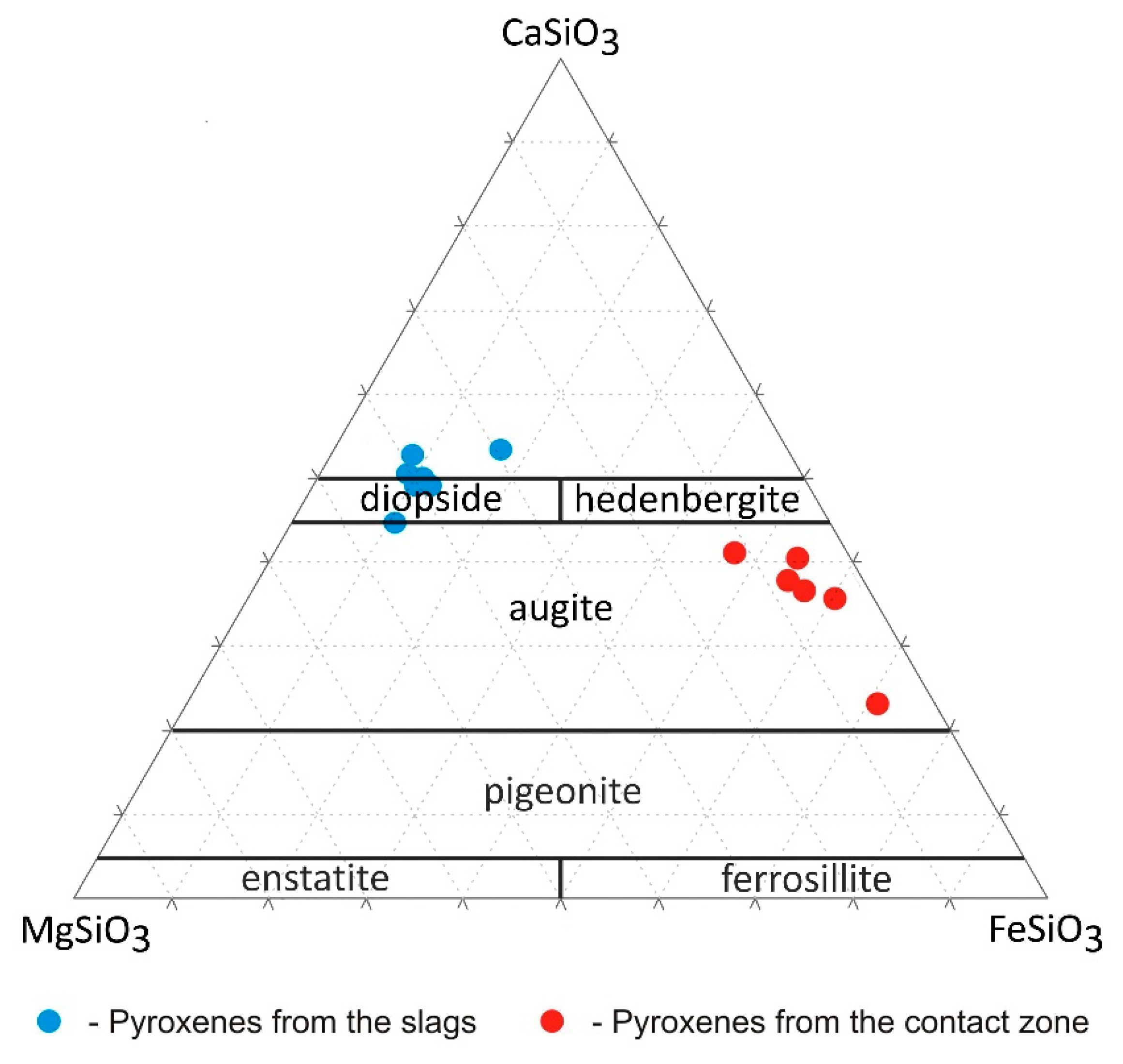
4.3.2. Silicates and Aluminosilicates

Mullite is common in refractory materials. In the studied sample, despite SiO2 and Al2O3, it concentrates Fe (up to 7.03 wt.% of Fe2O3) and Ti (less than 1 wt.% of TiO) (Table 4). Mullite crystals are characterized by chemical zonation. The zones are associated with differences in Fe and Al content, where the rim is relatively enriched in Fe (up to 7.10 wt.% of Fe2O3) (Table 4), replacing the Al2O3 (Table 4).
Mullite at the contact zone is chemically similar to this from refractories. It consists of Al (up to 72.81 wt.% of Al2O3), Si (up to 25.89 wt.% of SiO2) and small amounts of Fe (up to 0.40 wt.% of Fe2O3), and Ti (up to 0.36 wt.% TiO) (Table 4). Apart from a small addition of Ti and Fe (Table 4), no significant substitutions were observed within the mullite crystals. Mullite does not occur in slags uncontaminated by refractories.
Feldspars are absent in refractory materials. In the slags, they are common and occur as both plagioclase and K-feldspar. Plagioclase forms a calcium member of the NaAlSi3O8-CaAl2Si2O8 series (An93). Additionally, Fe (up to 1.62 wt.% of Fe2O3), Zn, and Ba (less than 1% by weight oxide) substitutions were observed (Table 4). Potassium feldspars are represented by microcline (KAlSi3O8) (Figure 3), with numerous substitutions, such as: Ba (up to 4.67 wt.% of BaO), Ti (up to 1.02 wt.% of TiO), and Na, Fe, Ca (less than 1 wt.% by oxide) (Table 4).
Feldspars occur often in the zone at the contact of slag with the refractory material. Plagioclases here are dominated by anorthite endmember (An96) (Table 4). Additionally, Fe (up to 1.45 wt.% of Fe2O3) and, to a lesser extent Zn, K, Ba, and Mg were observed in the anorthites (Table 4). Potassium feldspars are more common in the contact area than in slags. Potassium feldspars from this zone are characterized by the significant Pb content in the range of 0.14–29.48 wt.% of PbO (Table 4). In addition to Pb, substitutions of Ba (up to 4.83 wt.% of BaO), Ca (up to 1.39 wt.% of CaO), Na (less than 1 wt.% of Na2O), Fe (less than 1 wt.% of oxide), Ti (less than 1 wt.% of TiO2), Mg (less than 1 wt.% of MgO), and sporadically Zn (up to 1.93 wt.% of ZnO) were observed (Table 4).
Pyroxenes are absent in refractory materials. In the slags, they have a composition corresponding to the diopside (CaMgSi2O6) (Table 4, Figure 5). In the tetrahedral positions that build Si2O6 chains, Si is replaced by Al (from 3.73 to 8.44 wt.% of Al2O3) (Table 4). The analysed pyroxenes also contain Zn (0.34–5.16 wt.% of ZnO) and small amounts of Ti, Na, Cr, and V (less than 1 wt.% of the oxide) in their structure (Table 4).
At the contact zone of the slags with the refractories, clinopyroxenes are common. Pyroxenes in the contact zone have a composition of the augite ((Ca,Mg,Fe)(Mg,Fe)Si2O6) (Table 4, Figure 5). In contrast to the pyroxenes from slags, here they are characterized by a low Ca content (up to 6.88 wt.% of CaO) (Table 4). The Si content in pyroxenes is up to 48.96 wt.% of SiO2, Zn up to 5.67 wt.% of ZnO, Al up to 1.44 wt.% of Al2O3, Mn up to 1.23 wt.% of MnO, and small amounts of Ti and Na (less than 1 wt.% of oxide) were observed (Table 4).
Melilite group minerals were also distinguished within the slags. The EPMA analysis results allowed them to be classified as alumoåkermanite—(Ca,Na)2(Mg,Al,Fe2+)Si2O7 (Table 4). Also, small substitutions of Zn (up to 2.13 wt.% of ZnO), Mn (up to 0.87 wt.% of MnO), Na (up to 0.67 wt.% of Na2O), Cr (up to 0.20 wt.% of Cr2O3), and K (up to 0.20 wt.% of K2O) occur in the melilite structure (Table 4).

4.3.3. Glass

The largest accumulations of glass are present at the neighborhood of the pores and the direct contact with refractory material. These phases consist mainly of different proportions of SiO2, PbO, and As2O3 (Table 5).
Two main types of glass can be distinguished: SiO2-dominated and PbO+As2O3-dominated. In silica-dominated glass, besides SiO2 (44.02–75.12 wt.%; Table 5), the following elements concentrate: Al (11.94–16.99 wt.% of Al2O3); Fe (0.39–14.34 wt.% of Fe2O3); Ba (0.23–13.43 wt.% of BaO); K (5.92–9.41wt.% of K2O); Ca (0.78–1.60 wt.% of CaO), Ti (1.02–1.43 wt.% of TiO2), Pb (0.00–3.18 wt.% of PbO), and Zn (0.00–1.23 wt.% of ZnO) (Table 5).
Lead-arsenic glasses are impoverished in Si (1.64–36.05 wt.% of SiO2), Al (0.24–4.09 wt.% of Al2O3) and K (0.21–0.42 wt.% of K2O) and enriched in Zn (2.68–6.60 wt.% of ZnO); As (15.37–15.52 wt.% of As2O3), and Pb (28.39–69.40 wt.% of PbO) (Table 5).
To confirm the amorphous nature of the phases, a Raman analysis of the phase containing Si, As, and Pb was performed (Figure 6).
The high values of full-width at half-maximum observed related to the PbO-SiO2-As2O3-Al2O3 material may suggest a more or less ordered network. Considering previous studies [46,47,48,49,50], the character of bands in similar materials ascribed to the glassy character of the material. More precisely, isomorphic substitution of arsenic and aluminum ions in a silica glass network leads to the formation of As-O-Si and Al-O-Si linkages and AsO43− or AlO64− structural units, respectively, due to the bands centered at 257, 437, 690, 750 cm−1. The position of those bands is slightly low considering what other papers reported in the literature [51]. The character and position of both bands is related to the elevated arsenic content and affected by the presence of lead ions occupied by the interstitial positions in the internal system. Three components at 879, 962, 1105 cm−1 may correspond to (1) orthosilicate or pyrosilicate units, (2) Si-OH stretching modes, (3) Q2 units with two non-bridging oxygens, as well as (4) Si-O-Si asymmetric stretching in disilicate units.

5. Discussion

In the analysed slags, we can distinguish two types of reactions: gas-refractory materials and melt-refractory materials. The result of the first type of reaction is mainly the enrichment of refractory materials with elements characteristic for Zn-Pb slags. To a lesser extent, such reactions led to the formation of new (mainly amorphous) phases (Figure 7). The reaction of melt with refractory materials leads mainly to the crystallization of new phases, or modification of the chemistry of existing ones.

5.1. Reactions of the Gas Phase with Refractory Materials

As already mentioned, the smelting of zinc was carried out by converting it to a gaseous form, followed by condensation in condensers. As well as zinc, other components of the charge were also vaporized during the metallurgical process (Table 6). Together with rising pressure within the muffle due to the vaporization of solid phases, it resulted in the formation of fluid that penetrated the cracks and crevices present in the refractories. In high-temperature conditions and due to a change in local chemical equilibrium conditions, the chemistry of the phases building the refractory material changes, and the formation of new phases may occur (Figure 7).
The first type of transformation that took place between the fluid and the refractory material was the enrichment of the latter in PbO, K, As, Zn, and Na2O. These elements migrate within refractories through the micropores and/or by diffusion. In the 19th-century metallurgical furnaces in Ruda Śląska, the temperature ranged approx. from 1000 to 1300 °C [34]. The PbO was present as a vapor after reaching a sufficiently high temperature, which for pure PbO is 1470 °C (Table 6). A suitable gas mixture composition could cause a reduction in the PbO boiling point (e.g., in the presence of As2O3, it can drop down to ca. 1000 °C [52]). The possibility of PbO evaporation (at temperatures of 1220–1320 °C) was also confirmed during research on the reduction of lead slags [53]. Potassium, sodium, arsenic, and zinc also migrated in gaseous form due to the low boiling points (Figure 7, Table 6). The fluid enriched in PbO, K, As, Zn, and Na2O reacted with the silicate phases occurring in refractories, causing them to release components through melting and/or diffusion. These components formed melt, which was pushed into the refractories (Figure 7). It was possible thanks to the lowering of the liquidus temperature of refractory materials to the conditions present during the smelting. Previous studies show that the liquidus temperature, with appropriate proportions for the SiO2-PbO system, can start from 700 °C [54]. The presence of other ingredients further reduced the liquidus temperature [52]. Aluminum-bearing phases in refractories did not melt due to too high melting points, even considering the influence of slag-related elements on their liquidus (Figure 7). The liquid which originated from the melting/diffusion of elements from the refractory phases was composed of FeO/Fe2O3, CaO, and MgO with possible minor amounts of SiO2 (Figure 7). It migrated inwards to the refractories until the point when temperature drop caused its recrystallization as submicroscopic phases (Figure 7). Its presence also limited further fluid migration (Figure 7).

5.2. Chemical and Phase Reactions on the Contact between Melt and Refractory Elements

In the melt from which slags crystallize, similar processes can be observed, which occur in the natural igneous intrusion. Therefore, the refractory components may be an equivalent to the rocks surrounding the igneous body.
Gravitational differentiation is one such process. In natural magmatic chambers, it occurs as fractional crystallization or as molecular differentiation [55]. Due to the long-term maintenance of high temperatures in the furnace, followed by the rapid cooling of the metallurgical melt, the phenomenon of selective phase crystallization and its sinking to the bottom is limited. For this reason, it can be assumed that after complete liquefaction of the metallurgical charge, the movement of molecules within the melt played a greater role. Compounds and elements with higher density, e.g., Fe or Pb (Table 6), during heating in the furnace, moved to the bottom of the retort and accumulated on the border with the solid (refractory material).
The enrichment of the phases in contact with the refractories in the Pb observed during the analysis may be due to gravitational differentiation during heating (before all the material was melted). Due to the low melting point (290 °C) (Table 6), the plattnerite (PbO2) present in the feed material liquefied before effective reduction began. The liquid form combined with high density (Table 6) enabled migration towards the bottom of the muffle already at the initial stages of the metallurgical process when other components were present in solid form. Then, during further heating, PbO2 disintegrated into PbO + O2 (Table 6). In this way, at the bottom of the muffle, zones of high density and increased oxygen content (from the breakdown of PbO2) were created, which weakened their reduction by C or CO. In this way, it was possible at a later stage to develop Pb-enriched mineral phases.
A similar situation occurred in the case of As2O3, whose melting point is just over 300 °C (Table 6). At a time when the furnace was at a relatively low temperature (~300 °C), As, along with the Pb migrated as a liquid, formed PbO2-As2O3 melt, and at a later stage, PbO-As2O3 melt.
Due to the high melting point (Table 6), in contrast to Pb and As, iron oxides did not melt and migrate in the early stages of smelting. Iron oxides melted together with other charge components after obtaining the liquidus temperature of the entire system. For this reason, its migration was possible only through the molecular differentiation of the metallurgical melt. The high density favored the separation (Table 6), thanks to which the contact zone was enriched with phases with a high iron content (Table 3, Table 4 and Table 5, Figure 5).
Considering that the metallurgical process was not perfect, some of the Zn did not evaporate or was not reduced to the metallic phase and also moved to the lower parts of the retort. In the resulting zones enriched in heavy metals, phases were formed, of which Pb, Fe, and Zn were one of the main components. After reaching the liquidus point of the system, Si and other components (e.g., Ca, K) were added into the PbO-As2O3 melt.
Another phenomenon observed in the samples was further contamination of the melt with the elements building refractory materials (mainly Si and Al; Table 2). The assimilation of cover rocks by a hot melt is a common phenomenon in nature and was the reason for the emergence of separate rock types in many parts of the world [55]. For slag, the melt partially dissolved the outermost parts of the refractories. This process in Zn metallurgy is common and was described as corrosion of refractory materials by a melt [43]. The migration of components that build refractories to the slag melt was also reported in an experiment conducted by De Wilde et al. [36].
As a result of the cooling of this complex PbO2-As2O3-rich melt, we observe crystallization of phases characteristic for a contact zone: alumohematite (Table 3), pyroxenes enriched in Fe and depleted in Ca (Table 4), and K-feldspar concentrating lead (up to 29.48 wt.% of PbO; Table 4). Similar type substitutions were described in slags after Zn production from other locations [9,33,34].
Due to the low melting temperatures (Table 6), Pb and As combined with residual (mainly SiO2) and incompatible (mainly K2O) components in the last stages of melt solidification formed an amorphous phase. These glasses were formed during the charge change, transport to the landfill, or at the landfill, because a rapid temperature drop was necessary for their creation. The occurrence of similar phases has been described in previous publications on the Zn metallurgy [9,12,33,34].

6. Conclusions

The study has proven that during the smelting of zinc in the 19th century metallurgical furnaces, reactions between the melt and the refractory materials took place. These include reactions of the batch components in the form of gas/fluid and liquid with refractories. Influence of gas/fluid manifested in the enrichment of parts of refractory materials in PbO, K, Na2O, and, to a lesser extent, As and Zn, with simultaneous displacement and transport of FeO/Fe2O3, MgO, and CaO into the refractories. As a result of temperature drops deeper in refractories, these elements accumulated to form a layer of submicroscopic phases. The reaction between the melt and the refractive materials is related to several processes. The first is gravitational differentiation leading to the formation of the liquid composed of high-density compounds characterized by low melting points, mainly PbO and As2O3. After reaching higher temperatures, the liquid phase was additionally enriched with other components of the charge (Fe, and to a lesser extent Zn, K, Mg, Ca, and Si). These elements (except FeO) only partly influence the composition of high-PbO and As2O3 melt due to low concentrations or lower densities. Changing the local liquidus course triggers the second process, which is the corrosion of refractory materials building the muffles. Melting of the refractory phases (mainly mullite and SiO2 polymorphs) enriches the PbO-As2O3 liquid in SiO2 and Al2O3. The third process is the crystallization of two melts: PbO-As2O3-FeO-SiO2-Al2O3 at the contact with refractory materials and K2O-MgO-CaO-SiO2 filling the rest of the muffle. Crystallization of these melts leads to the formation of different assemblages: quartz + alumohematite + pyroxene + feldspars + mullite + glass building the contact zone and spinel + pyroxene + melilite + feldspar building the slag. Additional differences are visible in the chemistry of phases, where at the contact zone, they are enriched in PTEs (mainly Pb and As). As was proven in previous studies, slags containing such phases pose a high environmental threat.

Author Contributions

Conceptualization, K.K. and R.W.; data curation, K.K. and R.W.; formal analysis, K.K., R.W., M.D. and D.Ś.; funding acquisition, R.W. and M.D.; investigation, K.K., R.W., M.D. and D.Ś.; methodology, R.W.; project administration, R.W.; resources, K.K. and R.W.; supervision, R.W.; validation, K.K. and R.W.; visualization, K.K., R.W. and M.D.; writing—original draft, K.K.; writing—review and editing, R.W. and D.Ś. All authors have read and agreed to the published version of the manuscript.

Funding

This study was supported by the National Science Center (NCN) grant no. 2016/21/N/ST10/00838 (awarded to RW), National Science Center (NCN) grant no. 2017/26/D/ST8/01117 (awarded to MD) and National Science Center (NCN) grant no. 2019/35/O/ST10/00313 (awarded to KK).

Conflicts of Interest

The authors declare no conflict of interest.

References

  1. Godzik, B.; Woch, M.W. History of mining in the Olkusz region. In Natural and Historical Values of the Olkusz Ore-Bearing Region; Polish Academy of Sciences: Krakow, Poland, 2015; pp. 29–37. [Google Scholar]
  2. De Windt, L.; Chaurand, P.; Rose, J. Kinetics of steel slag leaching: Batch tests and modeling. Waste Manag. 2011, 31, 225–235. [Google Scholar] [CrossRef] [Green Version]
  3. Ettler, V.; Legendre, O.; Bodean, F.; Touray, J.C. Primary phases and natural weathering of old lead-zinc pyrometallurgical slag from Príbram, Czech Republic. Can. Miner. 2001, 39, 873–888. [Google Scholar] [CrossRef] [Green Version]
  4. Ettler, V.; Mihaliewic, M.; Touray, J.C.; Piantone, P. Leaching of polished sections: An integrated approach for studying the liberation of heavy metals from lead-zinc metallurgical slags. Bull. Société Géologique Fr. 2002, 173, 161–169. [Google Scholar] [CrossRef]
  5. Kucha, H.; Martens, A.; Ottenburgs, R.; De Vos, W.; Viaene, W. Primary minerals of Zn-Pb mining and metallurgical dumps and their environmental behavior at Plombières, Belgium. Environ. Geol. 1996, 27, 1–15. [Google Scholar] [CrossRef]
  6. Liu, T.; Li, F.; Jin, Z.; Yang, Y. Acidic leaching of potentially toxic metals cadmium, cobalt, chromium, copper, nickel, lead, and zinc from two Zn smelting slag materials incubated in an acidic soil. Environ. Pollut. 2018, 238, 359–368. [Google Scholar] [CrossRef] [PubMed]
  7. Ming, X.; Faheem, M.; Linghao, Z.; Shan, L.; Xiao, H.; Binquan, J.; YanChyuan, S.; Dongwei, L. Solidification/stabilization of lead-zinc smelting slag in composite based geopolymer. J. Clean. Prod. 2019, 209, 1206–1215. [Google Scholar]
  8. Mouni, L.; Belkhiri, L.; Bouzaza, A.; Bollinger, J.C. Chemical associations and sorption capacity of Pb and Zn: Column experiments on a polluted soil from the Amizour mining district (Algeria). Environ. Earth Sci. 2016, 75, 96. [Google Scholar] [CrossRef]
  9. Piatak, N.M.; Seal, R., II. Mineralogy and the release of trace elements from slag from the Hegeler Zinc smelter, Illinois (USA). Appl. Geochem. 2010, 25, 302–320. [Google Scholar] [CrossRef]
  10. Piatak, N.M.; Parsons, M.B.; Seal, R.R., II. Characteristics and environmental aspects of slag: A review. Appl. Geochem. 2015, 57, 236–266. [Google Scholar] [CrossRef]
  11. Tyszka, R.; Kierczak, J.; Pietranik, A.; Ettler, V.; Mihaljevic, M. Extensive weathering of zinc smelting slag in a heap in Upper Silesia (Poland): Potential environmental risks posed by mechanical disturbance of slag deposits. Appl. Geochem. 2014, 40, 70–81. [Google Scholar] [CrossRef]
  12. Warchulski, R.; Mendecki, M.; Gawęda, A.; Sołtysiak, M.; Gadowski, M. Rainwater-induced migration of potentially toxic elements from a Zn–Pb slag dump in Ruda Śląska in light of mineralogical, geochemical and geophysical investigations. Appl. Geochem. 2019, 109, 104396. [Google Scholar] [CrossRef]
  13. Ettler, V.; Mihaljevič, M.; Jarošíková, A.; Culka, A.; Kříbek, B.; Majer, V.; Vaněk, A.; Penížek, V.; Sracek, O.; Mapani, B.; et al. Vanadium-rich slags from the historical processing of Zn–Pb–V ores at Berg Aukas (Namibia): Mineralogy and environmental stability. Appl. Geochem. 2020, 114, 1935–2016. [Google Scholar] [CrossRef]
  14. Mendecki, M.; Warchulski, R.; Szczuka, M.; Środek, D.; Pierwoła, J. Geophysical and petrological studies of the former lead smelting waste dump in Sławków, Poland. J. Appl. Geophys. 2020, 179, 104080. [Google Scholar] [CrossRef]
  15. Geseler, J. Use of stellworks slag in Europe. Waste Manag. 1996, 16, 59–63. [Google Scholar] [CrossRef]
  16. Alwaeli, M. Application of granulated lead–zinc slag in concrete as an opportunity to save natural resources. Radiat. Phys. Chem. 2013, 83, 54–60. [Google Scholar] [CrossRef]
  17. Warchulski, R.; Gawęda, A.; Janeczek, J.; Kądziołka-Gaweł, M. Mineralogy and origin of coarse-grained segregations in the pyrometallurgical Zn-Pb slags from Katowice-Wełnowiec (Poland). Mineral. Petrol. 2016, 110, 681–692. [Google Scholar] [CrossRef] [Green Version]
  18. Zieliński, K.; Rzeszowski, M. Wykorzystanie odpadów hutniczych w przemyśle cementowym. Hut. Wiadomości. Hut. 2007, 74, 610–615. [Google Scholar]
  19. Motz, H.; Geiseler, J. Products of steel slags an opportunity to save natural resources. Waste Manag. 2001, 21, 285–293. [Google Scholar] [CrossRef]
  20. Bosecker, K. Bioleaching: Metal solubilization by microorganisms. FEMS Microbiol. Rev. 1997, 20, 591–604. [Google Scholar] [CrossRef]
  21. Fečko, P.; Zechner, V.; Guziurek, M.; Lyčková, B.; Pertile, E. Zastosowanie ługowania bakteryjnego do odpadów ze starych składowisk ekologicznych usytuowanych w regionie Karlove Vary. Inżynieria Miner. 2012, 13, 55–64. [Google Scholar]
  22. Hołda, A.; Kisielowska, E. Biological removal of Cr(VI) ions from aqueous solutions by Trichoderma viride. Physicochem. Probl. Miner. Process. 2013, 49, 47–60. [Google Scholar]
  23. Chiarantini, L.; Benvenuti, M.; Costagliola, P.; Fedi, M.E.; Guideri, S.; Romualdi, A. Copper production at Baratti (Populonia, southern Tuscany) in the early Etruscan period (9th–8th centuries BC). J. Archaeol. Sci. 2009, 36, 1626–1636. [Google Scholar] [CrossRef]
  24. Ettler, V.; Cervinka, R.; Johan, Z. Mineralogy of medieval slags from lead and silver smelting (Bohutín, Příbram district, Czech Republic): Towards estimation of historical smelting conditions. Archaeometry 2009, 51, 987–1007. [Google Scholar] [CrossRef]
  25. Ettler, V.; Johan, Z.; Zavřel, J.; Wallisová, M.S.; Mihaljevič, M.; Šebek, O. Slag remains from the Na Slupi site (Prague, Czech Republic): Evidence for early medieval non-ferrous metal smelting. J. Archaeol. Sci. 2015, 53, 72–83. [Google Scholar] [CrossRef]
  26. Toffolo, L.; Addis, A.; Martin, S.; Nimis, P.; Rottoli, M.; Godard, G. The Misérègne slag deposit (Valle d’Aosta, Western Alps, Italy): Insights into (pre-)Roman copper metallurgy. J. Archaeol. Sci. Rep. 2018, 19, 248–260. [Google Scholar] [CrossRef]
  27. Warchulski, R.; Juszczuk, P.; Gawęda, A. Geochemistry, petrology and evolutionary computations in the service of archaeology: Restoration of the historical smelting process at the Katowice–Szopienice site. Archaeol. Anthropol. Sci. 2018, 10, 1023–1035. [Google Scholar] [CrossRef] [Green Version]
  28. Cabała, J.; Warchulski, R.; Rozmus, D.; Środek, D.; Szełęg, E. Pb-Rich slags, minerals, and pollution resulted from a medieval Ag-Pb smelting and mining operation in the Silesian-Cracovian region (Southern Poland). Minerals 2020, 10, 28. [Google Scholar] [CrossRef] [Green Version]
  29. Burger, E.; Bourgarit, D.; Wattiaux, A.; Fialin, M. The reconstruction of the first copper-smeltingprocesses in Europe during the 4th and the 3rd millennium BC: Where does the oxygen come from? Appl. Phys. A 2010, 100, 713–724. [Google Scholar] [CrossRef]
  30. Kierczak, J.; Pietranik, A. Mineralogy and composition of historical Cu slags from the Rudawy Janowickie mountains, southwestern Poland. Can. Mineral. 2011, 49, 1281–1296. [Google Scholar] [CrossRef] [Green Version]
  31. Piatak, N.; Seal, R., II. Mineralogy and environmental geochemistry of historical iron slag, Hopewell Furnace National Historic Site, Pennsylvania, USA. Appl. Geochem. 2012, 27, 623–643. [Google Scholar] [CrossRef]
  32. Ströbele, F.; Wenzel, T.; Kronz, A.; Hildebrandt, L.H.; Markl, G. Mineralogical and geochemical characterization of high-medieval lead–silver smelting slags from Wiesloch near Heidelberg (Germany)—An approach to process reconstruction. Archaeol. Anthropol. Sci. 2010, 2, 191–215. [Google Scholar] [CrossRef] [Green Version]
  33. Warchulski, R.; Gawęda, A.; Kądziołka-Gaweł, M.; Szopa, K. Composition and element mobilization in pyrometallurgical slags from the Orzeł Biały smelting plant in the Bytom–Piekary Śląskie area, Poland. Mineral. Mag. 2015, 79, 459–483. [Google Scholar] [CrossRef]
  34. Warchulski, R. Zn-Pb slag crystallization: Evaluating temperature conditions on the basis of geothermometry. Eur. J. Mineral. 2016, 28, 375–384. [Google Scholar] [CrossRef]
  35. Warchulski, R.; Gawęda, A.; Kupczak, K.; Banasik, K.; Krzykawski, T. Slags from Ruda Śląska, Poland as a large-scale laboratory for the crystallization of rare natural rocks: Melilitolites and paralavas. Lithos 2020, 372–373, 105666. [Google Scholar] [CrossRef]
  36. De Wilde, E.; Bellemans, I.; Campforts, M.; Guo, M.; Blanpain, B.; Moelans, N.; Verbeken, K. Investigation of high-temperature slag/copper/spinel interactions. Metall. Mater. Trans. B 2016, 47, 3421–3434. [Google Scholar] [CrossRef] [Green Version]
  37. Puziewicz, J.; Zainoun, K.; Bril, H. Primary phases in pyrometallurgical slags from a zinc-smelting waste dump, Świętochłowice, Upper Silesia, Poland. Can. Mineral. 2007, 45, 1189–1200. [Google Scholar] [CrossRef]
  38. Tyszka, R.; Pietranik, A.; Kierczak, J.; Zieliński, G.; Darling, J. Cadmium distribution in Pb-Zn slags from Upper Silesia, Poland: Implications for cadmium mobility from slag phases to the environment. J. Geochem. Explor. 2018, 186, 215–224. [Google Scholar] [CrossRef] [Green Version]
  39. Jonczy, I.; Gawor, Ł. Coal mining and post-metallurgic dumping grounds and their connections with exploitation of raw materials in the region of Ruda Śląska. Arch. Min. Sci. 2017, 62, 301–311. [Google Scholar] [CrossRef]
  40. Geoportal. Available online: geoportal.gov.pl (accessed on 10 July 2020).
  41. Dębicki, J. Przemysł Cynkowy. Szkic Historyczno-Gospodarczy; Skład główny; Gebethner i Wolff: Warszawa, Poland, 1927. [Google Scholar]
  42. Dobis, N. Przemysł Cynku i Ołowiu w Polsce; Chrześcijańska Drukarnia “Nakładowa”: Będzin, Poland, 1938. [Google Scholar]
  43. Domański, W.; Krupkowski, A. Metalurgia Cynku i Kadmu; Państwowe Wydawnictwo Naukowe: Warszawa, Poland, 1954. [Google Scholar]
  44. Piernikarczyk, J. Historia Górnictwa i Hutnictwa na Górnym Śląsku. Cz. 2; Śląski Związek Akademicki: Katowice, Poland, 1936. [Google Scholar]
  45. Morimoto, N. Nomenclature of Pyroxenes. Mineral. Petrol. 1988, 39, 55–76. [Google Scholar] [CrossRef]
  46. Brawer, S.A.; White, W.B. Raman spectroscopic investigation of the structure of silicate glasses (II). Soda-alkaline earth-alumina ternary and quaternary glasses. J. Non Cryst. Solids 1977, 23, 261–278. [Google Scholar] [CrossRef]
  47. McMillan, P. Structural studies of silicate glasses and melts—Applications and limitations of Raman spectroscopy. Am. Mineral. 1984, 69, 622–644. [Google Scholar]
  48. Mysen, B.O.; Finger, L.W.; Virgo, D.; Seifert, F.A. Curve-fitting of Raman spectra of silicate glasses. Am. Mineral. 1982, 67, 686–695. [Google Scholar]
  49. Neuville, D.R.; De Ligny, D.; Henderson, G.S. Advances in Raman spectroscopy applied to earth and material sciences. Rev. Mineral. Geochem. 2014, 78, 509–541. [Google Scholar] [CrossRef]
  50. Seifert, F.A.; Mysen, B.O.; Virgo, D. Three-dimensional network structure of quenched melts (glass) in the systems SiO2–NaAlO2, SiO2–CaAl2O4 and SiO2–MgAl2O4. Am. Mineral. 1982, 67, 696–717. [Google Scholar]
  51. Konijnendijk, W.L.; Buster, J.H.J.M. Raman-scattering measurements of silicate glasses containing sulphate. J. Non-Cryst. Solids 1977, 23, 401–418. [Google Scholar] [CrossRef]
  52. Bale, C.W.; Bélisle, E.; Chartrand, P.; Decterov, S.A.; Eriksson, G.; Gheribi, A.E.; Hack, K.; Jung, I.H.; Kang, Y.B.; Melançon, J.; et al. FactSage thermochemical software and databases, 2010–2016. Calphad 2016, 54, 35–53. [Google Scholar] [CrossRef] [Green Version]
  53. Jahanshahi, S.; Wright, S. Kinetics of reduction of CaO-FeOx-MgO-PbO-SiO2 slags by CO-CO2 gas mixtures. Metall. Mater. Trans. B 2017, 48, 2057–2066. [Google Scholar] [CrossRef]
  54. Shevchenko, M.; Jak, E. Experimental phase equilibria studies of the PbO–SiO2 system. J. Am. Ceram. Soc. 2018, 101, 458–471. [Google Scholar] [CrossRef]
  55. Cullers, R.L. Magmatic processes. In Geochemistry. Encyclopedia of Earth Science; Springer: Dordrecht, The Netherlands, 1998; pp. 373–414. [Google Scholar]
  56. Pubchem. Available online: https://pubchem.ncbi.nlm.nih.gov/ (accessed on 2 September 2020).
  57. Perry, R.H.; Chilton, C.H. Chemical Engineers’ Handbook, 5th ed.; McGraw-Hill: New York, NY, USA, 1973; p. 50. [Google Scholar]
  58. Gavrichev, K.; Bolshakov, A.; Kondakov, D.; Khoroshilov, A.; Denisov, S. Thermal transformations of lead oxides. J. Therm. Anal. Calorim. 2008, 92, 857–863. [Google Scholar] [CrossRef]
  59. Qu, Y.; Yang, Y.; Zou, Z.; Zeilstra, C.; Meijer, K.; Boom, R. Thermal decomposition behaviour of fine iron ore particles. ISIJ Int. 2014, 54, 2196–2205. [Google Scholar] [CrossRef] [Green Version]
  60. Helsen, L.; Van den Bulck, E.; Van Bael, M.K.; Vanhoyland, G.; Mullens, J. Thermal behaviour of arsenic oxides (As2O5 and As2O3) and the influence of reducing agents (glucose and activated carbon). Thermochim. Acta 2004, 414, 145–153. [Google Scholar] [CrossRef]
Figure 1. (A) Location map of the landfill in Ruda Śląska (based on data from geoportal.gov.pl [40]); (B) image showing a Silesian method smelting furnace from the Upper Silesia region [41].
Minerals 10 01006 g001
Figure 2. Macroscopic images of (A) representative slag sample and (B) its cross-section containing contact between slag (dark parts) and refractory materials (light parts).
Minerals 10 01006 g002
Figure 3. Diffraction pattern of slags and refractory material from Ruda Śląska.
Minerals 10 01006 g003
Figure 4. BSE (Backscattered Electrons) image of: (A) refractory material, (B) slag, (C) the contact zone of the slag with the refractories, (D) the intrusion of slag melt (left side of the dotted line) within refractory material (right side). Abbreviations: an—anorthite, cpx—clinopyroxene, gl—glass, mc—microcline, mul—mullite, spl—spinel, qz—quartz.
Minerals 10 01006 g004
Figure 5. Ternary classification diagram of pyroxenes from the slags and the contact zone (based on Morimoto, 1988 [45]).
Minerals 10 01006 g005
Figure 6. Raman spectrum of 45PbO-28SiO2-xAs2O3 glass measured from Ruda Śląska slags. A peak-fitting analysis was done using Voigt function with preservation of the minimum number of components.
Minerals 10 01006 g006
Figure 7. EPMA mapping showing concentrations of selected elements near the crack in the refractory materials.
Minerals 10 01006 g007
Table 1. Standards used during EPMA calibration.
ElementStandardElementStandardElementStandard
NaNaAlSi3O8AlKAlSi3O8MnMnSiO3
AsGaAsKKAlSi3O8SBaSO4
SiCaMgSi2O6FeFe2O3TiTiO2
MgCaMgSi2O6ZnZnSPbPbCrO4
CaCaMgSi2O6NiNiOPYPO4
CrCr2O3ClNa4BeAlSi4O12ClBaBaSO4
CoCoOSrSrSO4VV2O5
Table 2. Chemical composition of slag and refractory material.
Oxide/ElementConcentrationSlagRefractory Material
SiO2%38.1765.70
TiO2%0.690.73
Al2O3%15.8129.08
Fe2O3%22.712.38
Cr2O3%0.020.03
MnO%0.410.02
BaO%0.710.02
MgO%5.730.30
CaO%10.560.41
K2O%1.580.59
Na2O%0.270.06
P2O5%0.250.08
TOT/C%0.050.02
TOT/S%0.130.03
LOI%−0.30.0
VPPM14197
NiPPM141135
ZnPPM>10,000223
AsPPM215523
SrPPM59064
ZrPPM156113
PbPPM3775145
Table 3. Representative EPMA data of the oxides.
OxideRefractory MaterialSlagContact Zone
qzcrnsplqzalhem
SiO298.710.020.4297.72bd
TiO2bdbd0.69bd0.28
Al2O30.8199.6843.980.1985.63
FeOcalc--13.740.28na
Fe2O3calc0.77--na13.07
MnOnana0.18bdbd
ZnOnana36.790.22na
MgOnana2.94bdbd
CaO0.29nabdbd0.11
K2O0.11nananabd
Total100.6999.798.7498.4199.09
ElementAtoms per formula unit
qzcrnsplqzalhem
Si0.99-0.010.99-
Ti4+--0.02--
Al0.0121.69-1.81
Fe2+--0.37--
Fe3+0.01---0.18
Mn-----
Zn--0.88--
Mg--0.14--
Ca-----
K-----
O2-2.003.004.002.003.00
Abbreviations: bd—below detection limit, na—no data, alhem—alumohematite, crn—corundum, spl—spinel, qz—quartz.
Table 4. Representative EPMA data for silicates occurring in the analysed samples.
OxideRefractory MaterialSlagContact Zone
mulcoremulrimcpx 1cpx 2mllmc 1an 1cpx 3mc 3mc 4an2mul
SiO225.5526.2344.2348.7437.9162.3144.9448.9660.2942.4045.9725.89
TiO20.900.740.220.72bd1.02bd0.150.360.11bd0.36
Al2O372.5264.848.443.735.7518.5633.771.4420.1219.3933.4272.81
FeOcalc--8.965.835.86--24.12-0.76-na
Fe2O3calc0.877.03---0.661.62-0.41 1.450.40
MnOnana0.600.480.87bdbd1.23bdbdbdbd
ZnOnana0.345.162.13bd0.295.67bd1.930.59na
BaOnanananana4.670.11bd4.830.430.19na
MgOnana10.6012.558.05bdbd9.61bd0.100.13na
CaObdbd25.5221.6936.360.3619.706.880.311.3918.98na
Na2Onanabd0.210.670.790.510.120.860.270.17na
K2Obdbdbdbd0.2011.650.32na13.264.800.38na
V2O3nanabd0.12bdnanananananana
Cr2O3nana0.19bd0.20nanananananana
PbOnananananabdbdbd0.1429.48bdna
Total99.8498.8499.1099.2398.00100.02101.2698.18100.58101.06101.2899.46
ElementAtoms per Formula Unit
mulcoremulrimcpx 1cpx 2mll 10mc 1an 1cpx 3mc 3mc 4an 2mul
Si1.831.941.711.871.832.932.071.992.872.522.111.85
Ti4+0.050.040.010.02-0.04-----0.02
Al6.125.640.380.170.331.031.840.071.131.361.816.15
Fe2+calc--0.290.190.24--0.82-0.04--
Fe3+calc0.050.39---0.020.06---0.050.02
Mn--0.020.010.03--0.040.02---
Zn--0.010.150.08-0.010.17-0.080.02-
Ba-----0.09--0.090.01--
Mg--0.610.720.58--0.58-0.010.01-
Ca--1.060.891.880.020.970.300.020.090.93-
Na---0.020.060.070.050.010.080.030.02-
K----0.010.700.02-0.800.360.02-
V3+------------
Cr3+--0.01-0.01-------
Pb---------0.47--
O2-13.0013.006.006.007.008.008.006.008.008.008.0013.00
Abbreviations: bd—below the detection limit, na—no data, an—anortite, cpx—clinopyroxene, mc—microcline, mll—melilite, mul—mullite.
Table 5. Representative EPMA data of glass occurring at the contact zone of slag and refractory materials.
Oxidegl 1gl 2gl 3gl 4 *gl 5 *
SiO265.9275.1244.021.6436.05
TiO21.021.271.430.110.70
Al2O315.9811.9416.990.244.09
Fe2O3calc1.510.3914.343.255.92
MnObdbdbd0.220.56
ZnObd1.23na2.686.60
BaO2.220.2313.43bdbd
MgO0.16bd0.21bdbd
CaO1.600.781.241.502.80
Na2O0.890.540.120.160.13
K2O9.415.926.270.420.21
PbObd3.180.5369.4028.39
Sb2O5bdnanabdbd
As2O3bdnana15.5215.37
SO3bdbd0.261.98bd
P2O5na0.14nanana
Clbdnana1.58bd
Total98.71100.7498.8498.70100.82
Abbreviations: gl—glass; bd—below detection limit; na—not analyzed; * data from [12].
Table 6. Density and melting and boiling points of the most common melt/slag components [56] (*-data from [57]).
ComponentDensity [g/cm3]Melting Point [°C]Boiling Point [°C]
Pb11.34327.41740
Fe7.8715382861
Zn7.13419907
As5.78817 1614
Mg1.746491100
Ca1.548421484
Na0.9797.82881.4
K0.8663.5758.8
PbO9.58881470
PbO29.382902
FeO5.713603414
Fe2O35.2415653
ZnO5.619752 360
As2O33.74312.8 *457.2 *
As2O54.33154
MgO3.5828003600
CaO3.3425702850
Na2O2.2712751275 5
K2O2.36
Al2O33.9720543000
SiO22.617132230
1 Arsenic melts only under high pressure. The given temperature applies to approx. 28 atm. 2 At a temperature of 330–570 °C, it decomposes to PbO [58]. 3 It decomposes to FeO at 1199.85 °C [59]. 4 At a temperature above 500 °C, it decomposes to As2O3 [60]. 5 Sublimes at melting point [56]. 6 It decomposes at 350 °C [56].
Publisher’s Note: MDPI stays neutral with regard to jurisdictional claims in published maps and institutional affiliations.

