Article

The Genetic Mechanism and Evolution Process of Overpressure in the Upper Ordovician–Lower Silurian Black Shale Formation in the Southern Sichuan Basin

1
Key Laboratory of Coal Bed Methane Resource & Reservoir Formation Process of the Ministry of Education, China University of Mining & Technology, Xuzhou 221116, China
2
School of resources and earth science, China University of Mining & Technology, Xuzhou 221116, China
3
The EMS Energy Institute and Leone Family Department of Energy and Mineral Engineering, The Pennsylvania State University, University Park, State College, PA 16802, USA
*
Author to whom correspondence should be addressed.
Minerals 2020, 10(3), 238; https://doi.org/10.3390/min10030238
Submission received: 25 January 2020 / Revised: 2 March 2020 / Accepted: 3 March 2020 / Published: 6 March 2020

Abstract

:
The overpressure phenomenon is a widespread occurrence in unconventional shale gas reservoirs. Multiple overpressure shale gas fields were discovered in southern China, and there is no doubt that the gas production per well increases with increasing pressure coefficient (the ratio of the reservoir fluid pressure to the corresponding normal hydrostatic pressure). Thus, successful evaluation and production strategies of organic-rich shale deposits require an understanding of the evolution of the pressure coefficient and its controlling factors in these deposits. In this paper, drilling engineering data of a typical well were collected, and clay mineral tests and overburden diffusion coefficient experiments were conducted. Based on multiphysics simulations, this paper analyzes the overpressure characteristics and formation mechanisms of overpressure in the Longmaxi Formation shale, as well as its geological evolution and controlling factors. The results show that the large amount of shale gas is the cause of overpressure formation rather than disequilibrium compaction. The simulation results show that pressure coefficients of the typical well range from 0.84 to 1.49. The current pressure coefficient increases with increasing pressure coefficient after the last hydrocarbon generation. A large initial pressure coefficient (>1.9), short lifting time (<100 Ma) and small lifting amplitude (<4000 m) are favorable for the preservation of shale gas.

1. Introduction

The black shales from the Wufeng Group (O3w) and the Longmaxi Group (S1l) are considered to be the most developed shale strata in China [1,2,3,4,5]. It has been proven by reservoir exploration and development that reservoir overpressure is an important indicator dominating the shale gas enrichment and production in southern China [6,7,8]. Thus, the genetic mechanism and evolution process of the overpressure in black shale provides a geological basis for exploration and development strategies of shale gas.
From a global perspective, the formation mechanisms of overpressure are distinctly different depending on the various geological backgrounds. Generally, the disequilibrium compaction, tectonic compression and generation of gaseous hydrocarbons are the main mechanisms that could generate considerable overpressures [6,7,8,9,10,11,12,13,14,15,16,17,18,19,20]. Presently, many scholars hold the opinion that the reservoir overpressure in the Longmaxi Formation is mainly caused by hydrocarbon generation [6,7,8]. However, there is a lack of in-depth research, especially quantitative studies on reservoir pressure evolution. A recent study simulated the evolution of reservoir pressure using the equation of state for supercritical methane [6]. However, the porosity variation in the reservoir during the uplift process and the shale gas diffusion loss in the long geological history were not considered in the calculations. Therefore, the complexity and typical peculiarity of combined controlling geological factors should be considered when simulating reservoir pressure to increase the applicability of the approach for shale gas exploration and development work.
The purpose of this paper is to examine the genetic mechanism and evolution process of the overpressure in the O3w–S1l shales. Specifically, the main work of this paper can be divided into three parts. (1) We used Basin Model software to reconstruct burial, thermal and hydrocarbon generation histories. In combination with the diagenetic evolution of clay minerals, the formation mechanism of the overpressure is roughly estimated. (2) We established a shale diffusion equation that considers both the real gas effect and the gas–solid coupling effect. Then, MATLAB software was used to simulate the reservoir pressure evolution during the uplift process after hydrocarbon generation by solving the aforementioned equation. (3) Finally, a detailed sensitivity analysis of geological factors, including the lifting range, lifting time and pore compression coefficient, on the shale gas reservoir performance is conducted.

2. Geological Background

The research area is located in the southern part of the Sichuan Basin, which is considered the most successful shale gas area in China [21]. The Sichuan Basin is a superimposed basin that has a complicated structural evolutionary history, including Caledonian, Hercynian, Indosinian, Yanshanian, and Himalayan periods [22]. Due to the high paleoproductivity and euxinic conditions, the southern part of the Sichuan Basin experienced the widespread accumulation of black shale deposits through the Ordovician and Silurian transition [23]. Subsequently, the sedimentary–tectonic evolution of the study area can be divided into the following five stages based on regional geological mapping data and previous research [22,24]: (1) The study area experienced sustained uplift causing the upper strata of the Silurian to become denuded during the Later Caledonian. (2) In the Late Hercynian, a series of marine carbonate deposition and marine–continental transitional coal-sedimentation layers were formed with an average thickness of 500 m. (3) During the Indosinian period, the Sichuan Basin experienced a transition from marine to continental sedimentation and the thickness of Triassic strata was approximately 1200 m. (4) During the Yanshanian period, approximately 2900 m of continental deposits were formed spanning from the Jurassic to the Cretaceous. (5) During the Himalayan period, the sedimentary caprock in the area was fully folded and fractured, forming the current tectonic features.

3. Samples and Analytical Methods

3.1. Samples

The shale samples in this study were collected from the Fendong section, which is not influenced by magma intrusion or faults. For the specific location of this section, please refer to our previous work [25]. Schematic stratigraphic units of the southern Sichuan Basin as shown in Figure 1a.

3.2. Overpressure Characterization

Here, pressure coefficient was used to quantify reservoir overpressure, and it was defined by the ratio of the reservoir fluid pressure to the corresponding normal hydrostatic pressure. Since the permeability of a shale gas reservoir is very low, it is very difficult to directly measure the reservoir pressure. Common methods of pore pressure measurement mainly include indirect measurement through drilling data [26], logging data [27] or seismic data [28]. Overpressure could be formed in the mudstone cap rock with disequilibrium compaction, and the pressure coefficient can be computed by the dc method and the sonic moveout value [26,27]. The principle of the dc index method is to calculate the formation pressure based on the relationship between the rate of mechanical drilling and the degree of compaction of the shale. Specifically, in addition to the factors in the drilling process, the relationship between the drilling time and various factors can be determined by the following equation [29]:
d = log ( R 60 N ) log ( 12 W 10 6 D )
where d is the exponent in the general drilling equation; R is the drilling time, m/h; N is the rotation speed of the drill, r/min; W is the drilling pressure, kN; and D is the drill bit diameter, mm.
In order to eliminate the influence of drilling fluid density, Rehm and Mc Clendon proposed a method to modify the d index [30]:
d c = d G H E C D
where GH is hydrostatic pressure gradient, g/cm3; ECD is the circulating equivalent density of drilling fluid, g/cm3.
Drilling engineering data show that dc is mainly controlled by reservoir pressure changes [26,27]. Under certain conditions, the dc index becomes larger as the depth of the well increases. When drilling a formation with an abnormal pressure, the measured dc deviates from the normal trend line. The equation for calculating the reservoir pressure gradient [27] is:
G p = G 0 ( G 0 G n ) ( d c n d c ) 1.2
where Gp is the abnormal reservoir pressure gradient, kg/m3; G0 is the overburden pressure gradient, kg/m3; Gn is the normal reservoir pressure gradient, kg/m3; and dcn is the normal dc index.
To study the well-log responses to overpressure, dc data of the CN well were collected. Calculated pressure coefficients by sonic logging using the Chinese oil and gas industry standard (SY/T 5623-1997) were also collected from production units located in the study area.

3.3. Auxiliary Experiments

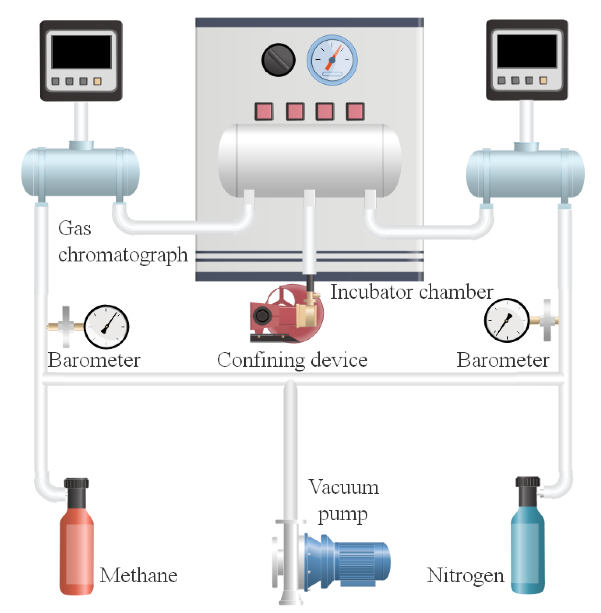
A natural gas diffusion coefficient experiment was conducted using the TK-I apparatus in the state key laboratory of oil and gas reservoir geology and exploitation, Southwest Petroleum University (Chengdu, China). Figure 2 shows a schematic diagram of the gas diffusion coefficient measurement apparatus. The main body of this apparatus consists of the confining pressure and temperature control system and gas chromatograph. The maximum experimental pressure can be as high as 69 MPa with 0.01% accuracy and the heating bath system temperature can reach 177 °C with an accuracy of ±0.1 °C to ensure the appropriate confining pressure and isothermal conditions. The gas diffusion coefficient experiment was performed with the above apparatus as follows:
(1) The sample was processed into a cylindrical sample with a diameter of 25 mm and a height of 20 mm;
(2) The cylindrical sample was then placed in a vacuum oven and dried at 70 °C under vacuum for 12 h or longer until the weight of the sample did not change;
(3) The cylindrical sample was then loaded into the sample chamber, and a certain confining pressure was applied according to the design scheme. Then, the experimental temperature of the incubator was set to a constant temperature for 2–2.5 h;
(4) After loading the sample, the vacuum pump was used to evacuate the core holder and the corresponding pipeline for at least 2 h;
(5) When complete vacuum was attained, nitrogen and methane were successively introduced into the diffusion chamber, the pressures of the two diffusion chambers were synchronously increased to 0.1 MPa, and when the pressure difference was smaller than 0.1 kPa, the gas source was disconnected;
(6) Gas samples were collected every 20 h during the experiment;
(7) The diffusion coefficient of the hydrocarbon gas was calculated according to Fick’s second law [31]:
D = ln ( Δ C 0 / Δ C i ) L A ( t i t 0 ) ( 1 V 1 + 1 V 2 )
where D is the diffusion coefficient of methane in the shale, cm2/s; ΔC0 is the difference in methane concentration between the two diffusion chambers at the initial moment, %; ΔCi is the difference in methane concentration between the two diffusion chambers at time i, %; ti indicates time i, s; t0 is the initial time, s; A is the cross-sectional area of the sample, cm2; L is the length of the rock sample, cm; and V1 and V2 are the volumes of the methane and nitrogen diffusion chambers respectively, cm3.
X-ray diffraction (XRD) analysis was performed using a RIGAKU D/Max-3B diffractometer at the Jiangsu Mineral Design and Research Institute (Xuzhou, China) to analyze the clay composition of the shale samples.

4. Basin Simulation

4.1. Burial and Thermal History Simulations

Basin Model software (CBMHS1.0, Key Laboratory of Coal Bed Methane Resource & Reservoir Formation Process of the Ministry of Education, Xuzhou, China) was used to reconstruct the burial and thermal histories of the CN well. In this study, the EASY%Ro simulation method of Burnham and Sweeney (1989) was used to calculate the chemical dynamic of the organic matter [32]. The parameters required for the simulations, including the stratigraphic thickness, lithology and vitrinite reflectance, were obtained from CN well completion reports. Other parameters are derived from our previous research [25]. It is worth noting that measuring the vitrinite reflectance of shale is more challenging as the vitrinite is well dispersed in shale matrix thus having a relatively smaller particle size and limited occurrence. Here, the equation proposed by Wilkins et al. [33] was used to calculate the equivalent random vitrinite reflectance values from Raman spectroscopy analyses.

4.2. Shale Reservoir Pressure Evolution Model

Based on the state equation of real gas, we developed a model for simulating the evolution of shale gas reservoir pressure that accommodates the material conservation equation of shale gas migration and the fluid–solid coupling law during the geological history of the reservoir. There are several assumptions in this model:
(1)
Shale gas occurs in the organic matter pores in both the free phase and the adsorbed phase.
(2)
The shale reservoir is isotropic, homogeneous and linear elastic.
(3)
The diffusion of shale gas and the elastic change in the shale matrix are isothermal.
(4)
Gas sorption follows the Langmuir isothermal behavior.
According to the real gas equation, the pressure of the gas can be expressed as:
P = Z n R T V = Z c R T
where P is the gas pressure, MPa; Z is the compression coefficient of a real gas, dimensionless; n is the number of gaseous molecular species, mol; c is the concentration of shale gas, mol/m3; R is the universal gas constant (8.314 J/(K mol)); T is the reservoir temperature, K.
R is a constant, but T, Z and C all change with the evolution process in the geological history of the reservoir. Undoubtedly, the change in T is determined by the simulation results of the geothermal history in the basin simulation. However, since the temperature and pressure states in the geological history of the reservoir differ greatly from the steady state of an ideal gas, the compression coefficient can be expressed by the following equation [34]:
Z = V r p r T r = 1 + B V r + C V r 2 + D V r 4 + E V r 4 + F V r 2 ( β + γ V r 2 ) e γ / V r 2
where Tc is the critical temperature above which gas cannot be liquefied by an increase in pressure, K; Pc is the lowest applied pressure required at the critical temperature to liquefy gas, MPa; and Vc is the volume of a fixed mass of fluid at Tc and Pc, m3. The mathematical expressions for each parameter are listed in Table 1.
Although a shale reservoir has a low diffusion coefficient, it is noteworthy that the shale gas lost by diffusion cannot be ignored during the long geological evolution history. Furthermore, as the amount of shale gas is continuously reduced during geological evolution, the porosities and diffusion coefficients of shale reservoirs are constantly changing. In other words, the process of fluid–solid coupling occurs during geological evolution which requires three equations to simulate.
The mass conservation equation for shale gas transport in diffusion can be expressed by:
( φ c k ) t + ( ε O M c a ) t = · ( φ D k c k ) + · ( ε O M D S c a )
where φ is porosity, t is geological time, Ma; εOM is the kerogen solid volume per unit volume of shale matrix (without pores); DS is the surface diffusion coefficient, m2/s; DK is the Knudsen diffusion coefficient, m2/s; ck is the free gas concentration of the shale reservoir, mol/m3; and ca is the shale matrix adsorption gas concentration, mol/m3.
The porosity changes with the effective stress of the shale matrix during the uplift process. The relationship between the porosity and effective stress can be expressed by the following equation:
φ = φ 0 e C φ ( σ p )
where φ0 is the porosity at which the effective stress is zero; Cφ is the pore compression coefficient, MPa−1; σ is the static rock pressure, MPa; and p is the reservoir pressure, MPa.
Similar to the change law of the porosity, the shale reservoir diffusion coefficient decreases exponentially with increasing effective stress:
D = D 0 e C D ( σ p )
where D0 is the porosity at which the effective stress is zero; and CD is the diffusion compression coefficient, MPa−1.
The pressure coefficient evolution model can be obtained by combining the above various equations. MATLAB simulation software (R2019a, MathWorks, Natick, MA, USA) was used to perform the calculations. The model is defined as a rectangle with a length, width and height of 220 km, 20 km and 150 m, respectively, which is consistent with the geological parameter background of the CN well. The initial conditions used in this model are as follows:
c ( x , y , z , t ) | t = 0 = c 0 = p 0 [ Z ( T 0 , p 0 ) R T 0 ]
The boundary conditions include Γ, where Γ represents the outer boundary. The outer boundary conditions of the model are set as follows:
c ( x , y , z , t ) | Γ = 0
The initial parameter values of the model are summarized in Table 2.
Before analyzing the evolution of the reservoir pressure coefficient and related major geological parameters, it is necessary to further describe the relationships among the variables and to evaluate the above numerical model.
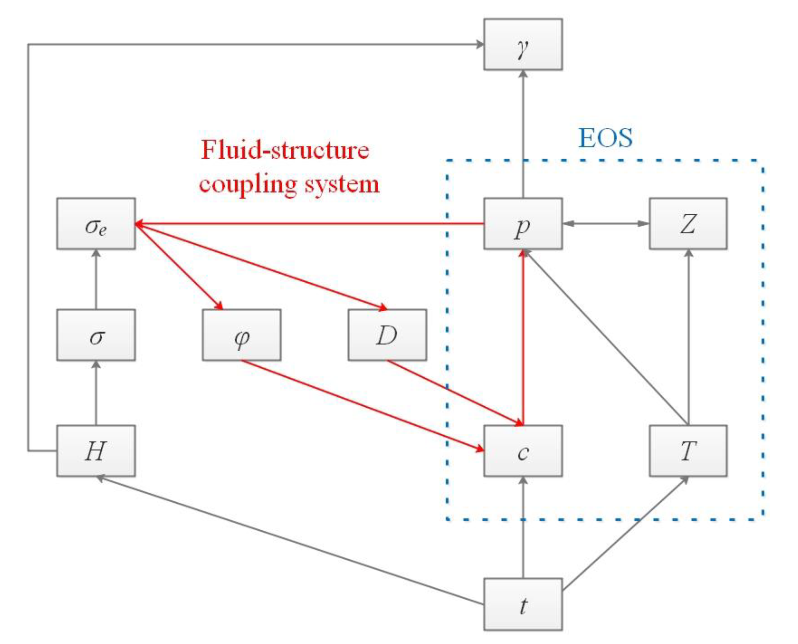
The pressure coefficient is a function of the buried depth and reservoir pressure. The reservoir pressure is directly determined by the gas state equation, which contains three variables, namely, Z, c and T. Z is determined by the reservoir pressure and temperature and therefore has a coupling relationship with the reservoir pressure. The gas concentration is obtained by the shale gas diffusion equation. The dynamic evolution of the reservoir pressure has a direct influence on the porosity and diffusion coefficient of the reservoir by changing the effective stress. Therefore, the internal variable p of the shale gas diffusion equation has a fluid–solid coupling relationship with D and φ, which appears as a closed loop path in the parameter transfer diagram, as shown Figure 3. The tectonic evolution experienced by the reservoir directly controls the basic parameters such as the depth and temperature.

5. Results

5.1. Reservoir Pressure State of CN Well in the Study Area

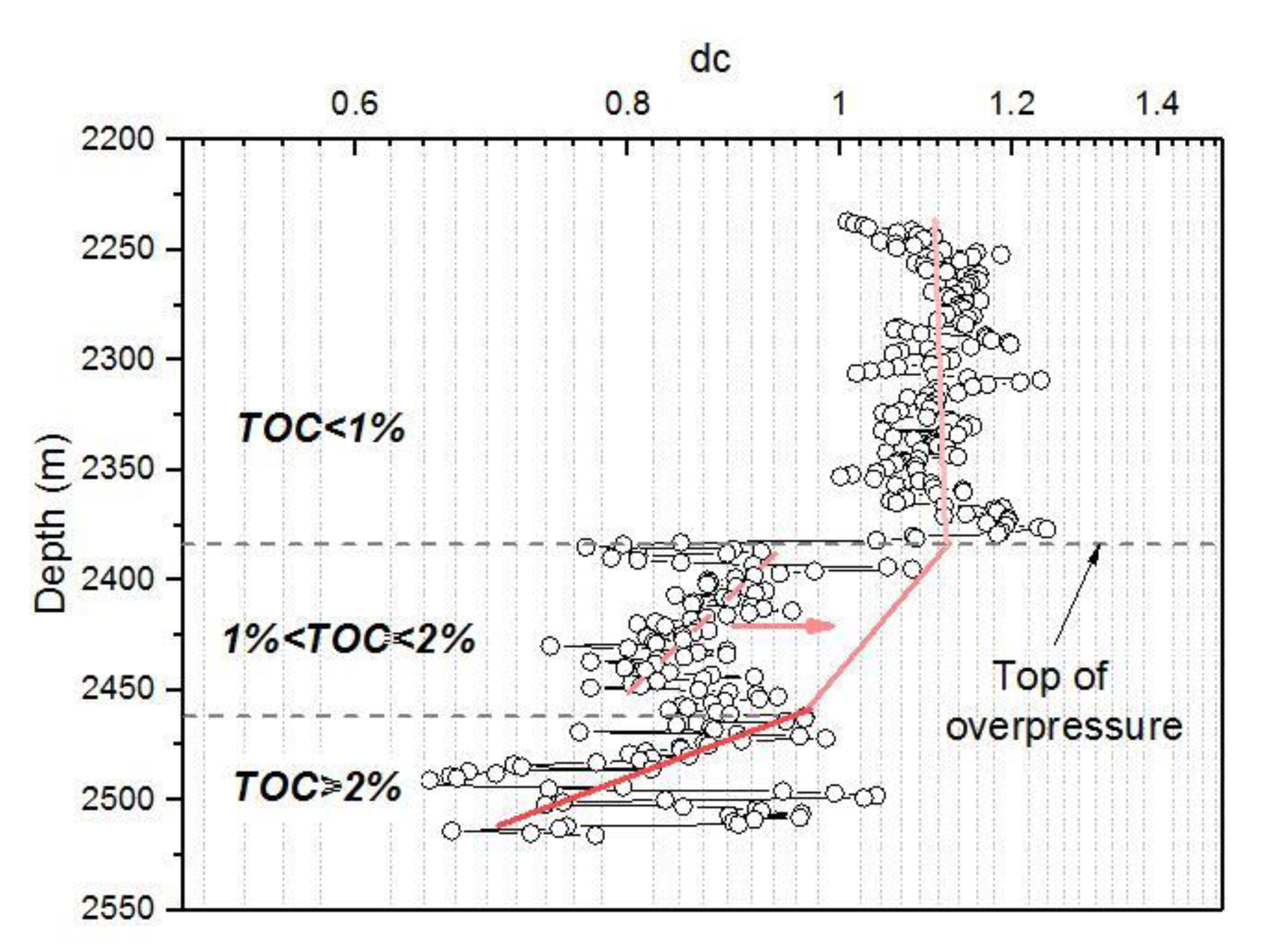
Figure 4 shows that there is no significant change in the dc value at the burial depth <2380 m. This finding indicates that the upper part of the Longmaxi Formation shale is basically subject to a normal reservoir pressure gradient. When the depth is greater than 2380 m, the dc index tends to decrease with increasing depth due to the overpressure in the lower part of the Longmaxi Formation. The reservoir pressure coefficient results calculated by sonic logging show that the shale reservoir pressure coefficient increases with increasing buried depth (Figure 5). The pressure coefficient at the bottom of the Longmaxi Formation reached a maximum of 2.0. However, it is worth noting that the method of indirectly calculating the reservoir pressure has certain limitations. The mineral composition of the Longmaxi Formation is not evenly distributed. Therefore, its physical properties are different under the same compaction conditions. Generally, the Longmaxi Formation has the characteristics of increased clay minerals and reduced carbonate minerals from top to bottom in the study area (Figure 1b). This difference in lithology may result in a larger calculated pressure coefficient. The formation pressure coefficient measured near the well location indicates that the formation pressure coefficient in the study area has an average of 1.62 (Figure 5). It is undeniable that there is a large formation pressure coefficient at the bottom of the Longmaxi Formation.

5.2. Burial, Thermal and Hydrocarbon Generation Histories of the O3w–S1l Shales

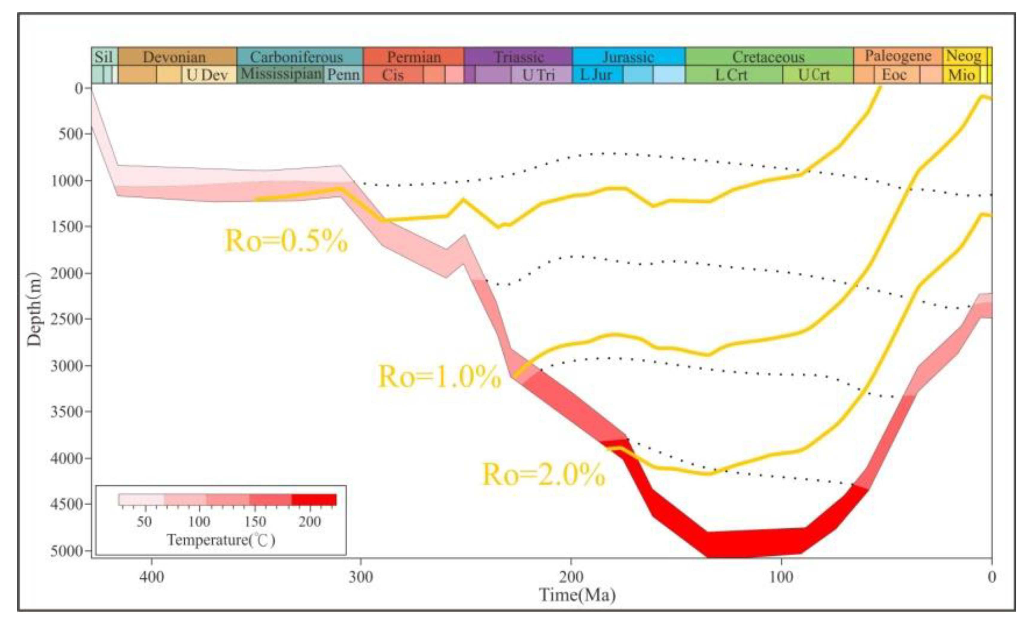
The basin simulation results indicate that the O3w–S1l shales in the study area have complex burial, thermal (Figure 6) and hydrocarbon generation evolution histories (Figure 7). Specifically, the evolution history can be divided into four stages corresponding to the regional geological background.
(1) The first stage lasted from the early Silurian to the middle of the Silurian. At this stage, the crust continued to subside, resulting in the deposition of Silurian strata dominated by marine clastic rocks. Burial of the Longmaxi Formation extended to the end of the Silurian, resulting in a buried depth of 1660 m. The paleothermal regime was normal, with a gradient of 30 °C/km [22]. The maturation level, as indicated by the vitrinite reflectance, is approximately 0.4%. The temperature of the organic matter at the bottom of the Longmaxi Formation was approximately 65 °C and had not yet entered the mature stage.
(2) The second stage lasted from the middle of the Silurian to the Late Carboniferous. The study area experienced the sustained uplift and exhumation of the Wufeng and Longmaxi Formations. The thickness of the remaining Silurian deposits was approximately 820 m in the CN well. Carboniferous and Devonian sediments were generally absent in the study area. Furthermore, there was essentially no hydrocarbon generation at this stage.
(3) The third stage begins in the early Permian and ends in the Late Cretaceous. Continuous deposition within the basin resulted in deep burial of the Longmaxi Formation. The regional geothermal field was higher than 35 °C/km in the Late Permian due to basaltic eruptions [22]. At the end of the Cretaceous, the bottom of the Longmaxi Formation had been buried more than 6000 m deep. Accordingly, the maximum palaeotemperature of the organic matter in the O3w–S1l shales was approximately 200 °C. Consequently, the maturation level was up to 2.68%, producing large amounts of natural gas, which is the main source of the shale gas in the Wufeng and Longmaxi Formations.
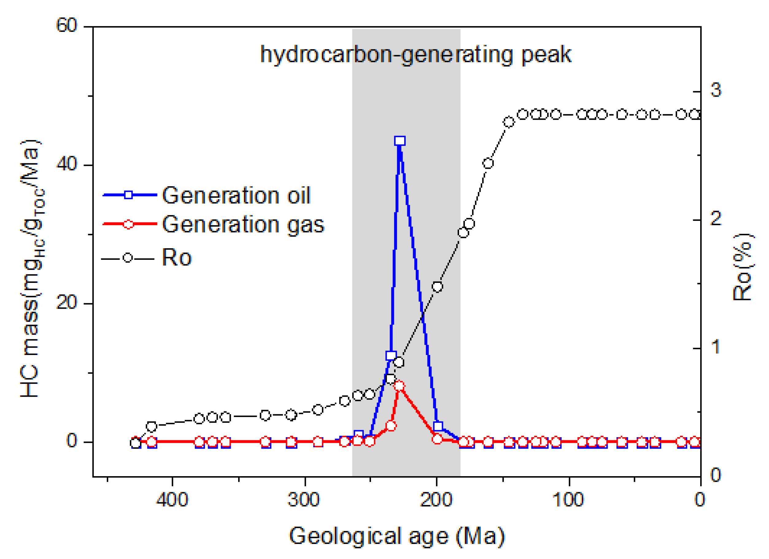
(4) The last stage lasted from the end of the Cretaceous to the present. The Himalayan orogeny caused the uplift and erosion of the Sichuan area (Figure 8); the palaeotemperature fell to below 120 °C, and the hydrocarbon generation of the organic matter ended.

5.3. Clay Mineral Composition

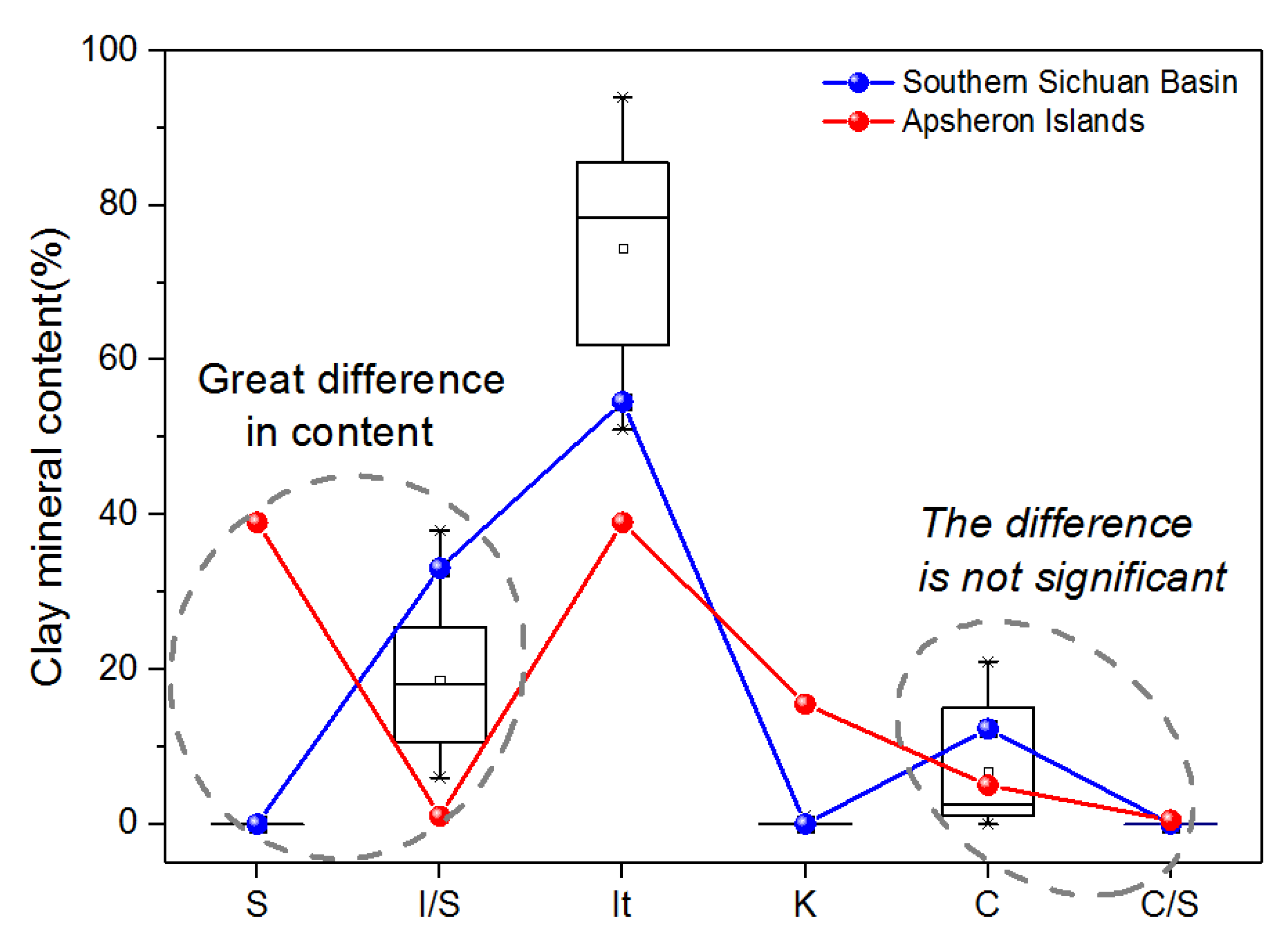
The percentage of clay minerals in the FD section sample is shown in Figure 9. The clay minerals are mainly composed of illite (I), chlorite (C) and an ionic mixture (I/S). Among these clay minerals, illite has the highest concentration, ranging from 51% to 94% (average = 74.5%). The andreattite content in the studied sections ranges from 6% to 38% (average = 18.65%), and the chlorite content ranges from 0% to 20.1% (average = 6.75%). Overall, the O3w–S1l shales of the FD section display higher concentrations of illite and have lower andreattite contents compared with the test data of other scholars in the study area [38].

5.4. Stress Sensitivity of Shale Diffusion Coefficient

The diffusion coefficient is a necessary parameter for calculating the amount of shale gas diffusion loss. Similar to the permeability, the diffusion coefficient has a strong stress sensitivity. The geological evolution of shale reservoirs is inevitably accompanied by changes in the diffusion coefficient. The shale-pressure–diffusion experiment shows that when the confining pressure increases from 10 to 30 MPa, the sample diffusion coefficient decreases from 6.3 × 10⁻¹² to 9.0 × 10⁻¹³ m2/s (Figure 10). The diffusion coefficient and the effective stress have the following exponential function relationship:
D = 10 11 e 0.09 ( σ p )
where D is the diffusion coefficient, m2/s; and σ−p is the effective stress, MPa.
Therefore, the attenuation of the diffusion coefficient decreases as the effective stress increases. This attenuation behaviour is similar to those of the porosity and permeability of shale reservoirs [40].

6. Discussion

6.1. Mechanism of Overpressure Generation

Previous studies have shown that the formation of reservoir overpressure mainly includes disequilibrium compaction, horizontal tectonic stress and organic hydrocarbon generation. A large number of studies have confirmed that the overpressures in the Gulf Coast Basin [41], the North Sea [42,43] and the Yinggehai Basin [44] were caused by disequilibrium compaction. Due to the high deposition rate of these basins, the fluid discharge in the thick mudstone is not even, and the high pressure fluid bears more of the overlying static rock pressure and results in a high pressure during the compaction process. It is worth noting that the shale reservoir temperature, pressure, and fluid chemical environment change during the burial process. Along with the dynamic changes in the physical and chemical environments, the shale material composition and structure inevitably have corresponding responses. Clay minerals are some of the main components in shale. The compositions of clay minerals and their content changes are sensitive to reservoir pressure and temperature conditions. Specifically, the pore fluid (water and gas) contained in shale affects both the direction and extent of clay mineral transformation during diagenesis. It is well known that illitization is accompanied by the precipitation of interlayer water, which is conducive to the progress of the conversion process if the interlayer water can be discharged smoothly. Conversely, various factors that hinder the expulsion of fluid from the clay layer reduce or even terminate the illitization process. Oilfield data show that there are unaltered smectites in the 6 km deep sediments of the Baku Islands (Figure 9). The high pressure generated by disequilibrium compaction causes illitization to be hindered due to a poor fluid discharge, thereby greatly increasing the depth of existence of smectite.
3 N a A l 7 S i 11 O 30 ( O H ) 6 + 7 K + + 4 O H = 7 K A l 3 S i 3 O 10 ( O H ) 2 + 4 H 2 O + 12 S i O 2 + 3 N a +
Among the black organic-rich shales of the Longmaxi Formation in the southern part of the Sichuan Basin and its periphery, the clay minerals have the highest mineral content of illite and illite/smectite, lack kaolinite and do not contain smectite. The above characteristics indicate that the reservoir fluids in the Longmaxi Formation are alkaline and rich in K+. However, the organic acid generated during the hydrocarbon generation process increases the concentration of H+ in the reservoir fluid, thereby hindering the illitization process. Therefore, it is speculated that the Longmaxi Formation has experienced a strong compaction before the peak of hydrocarbon generation, and all of the smectites have been converted into illite or illite/smectite. It is concluded that the overpressure of the Longmaxi Formation is not mainly caused by the disequilibrium compaction effect similar to the Caspian basin (Figure 11).
Previous studies have shown that the conversion of organic matter or liquid hydrocarbons into gaseous fluids can lead to a rapid increase in fluid volume within the reservoir [45]. Shale is a tight reservoir with slow hydrocarbon expulsion. Cracking of only 1% by volume of the oil in sealed rock can theoretically produce a static overpressure [11,46,47]. The equivalent vitrinite reflectance (Ro) of the O3w–S1l shales is approximately 2.7–2.9%, indicating that the source rock reaches the mature stage. Basin simulation results reveal that shale produces a large amount of natural gas before the maximum depth. Therefore, the large amount of gas produced by the conversion of kerogen and liquid hydrocarbons may be the main cause of the abnormal high pressure in the O3w–S1l shale. This conclusion is consistent with the results of other scholars [6,8].

6.2. Overpressure Evolution of the CN Well

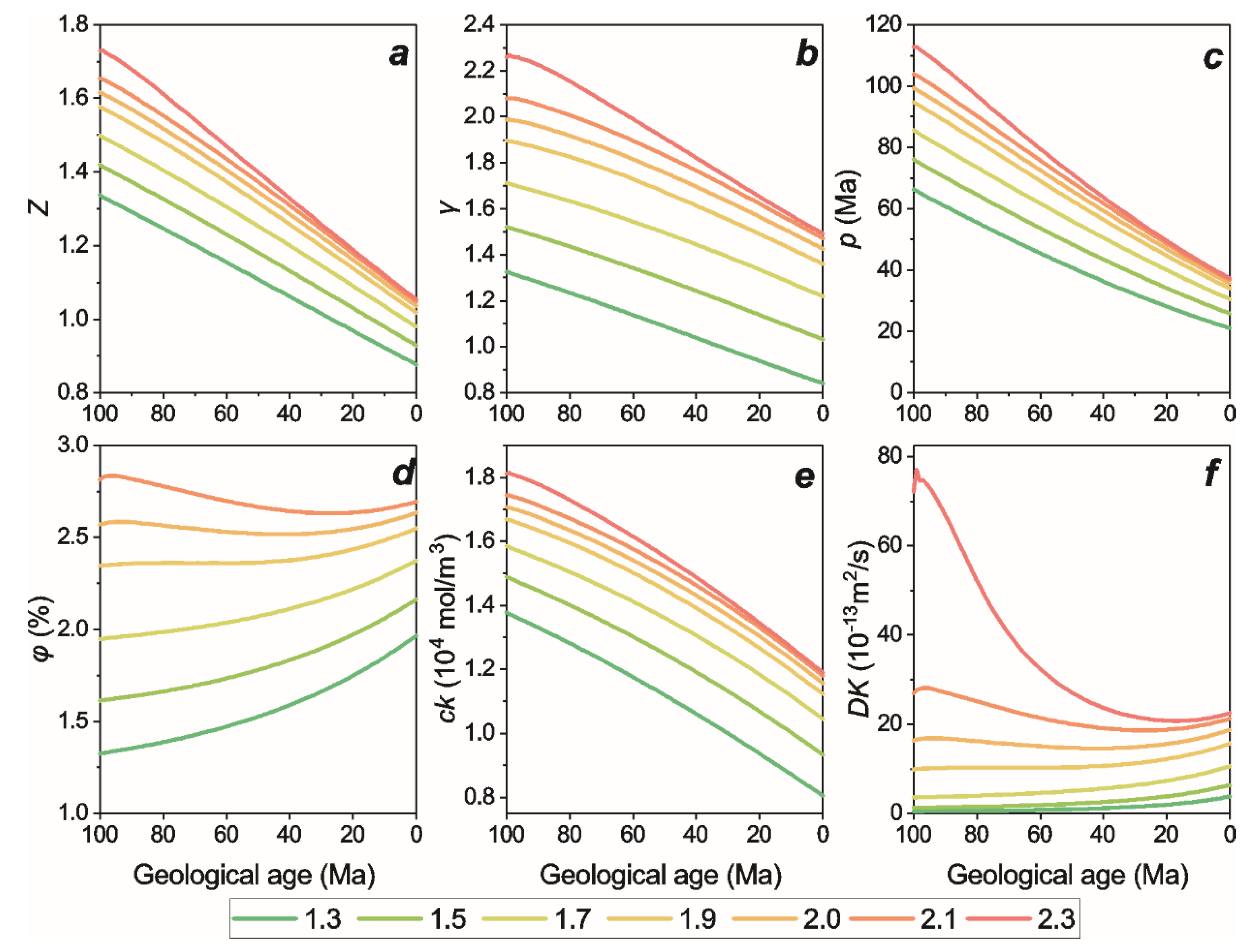
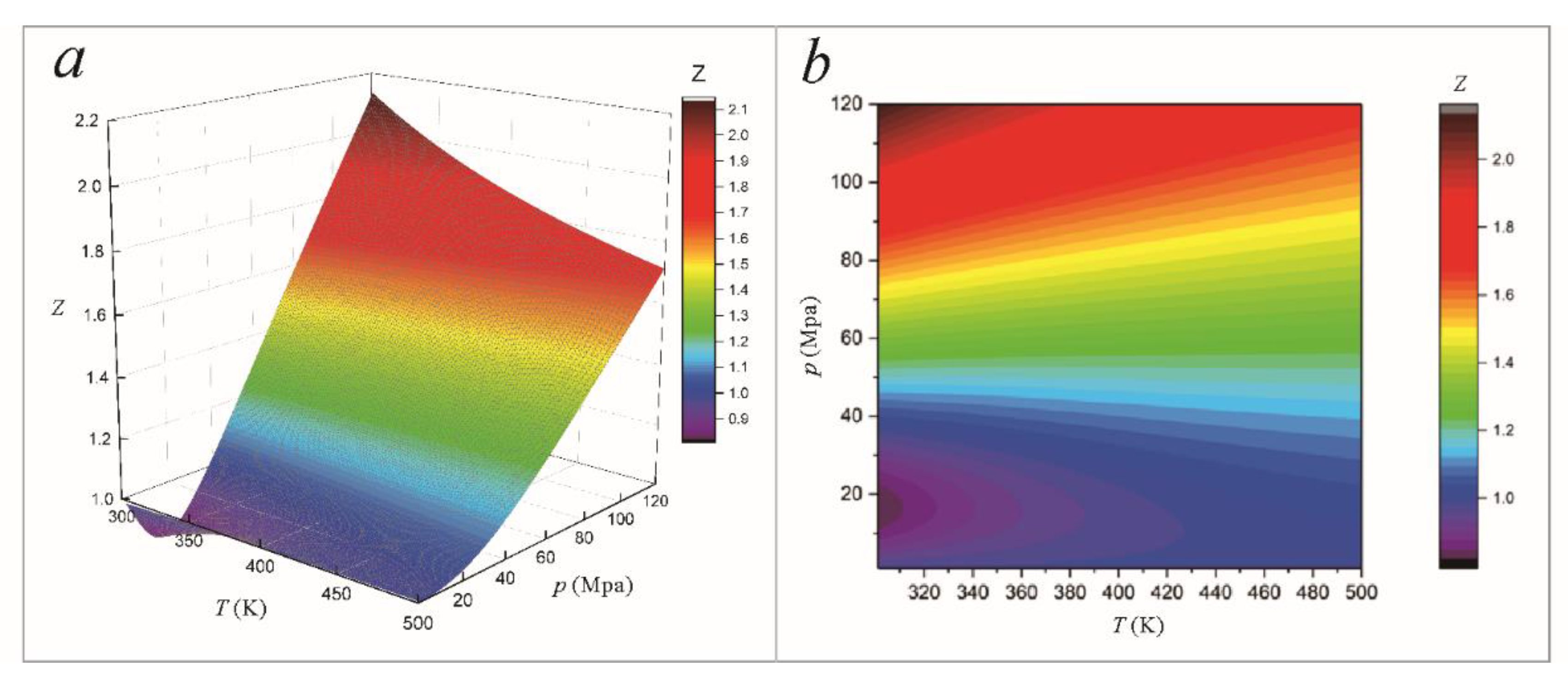
The fluid inclusion test results of adjacent blocks show that the estimated trapping pressure of methane in the shale reservoir at the maximum burial depth is 90.3–139.4 MPa, and the pressure coefficient at this time is approximately 1.31 to 2.31 [6]. Therefore, the reservoir pressure evolution simulations are carried out with pressure coefficients of 1.3, 1.5, 1.7, 1.9, 2.0, 2.1 and 2.3 as the initial values. The results show that the pressure coefficient evolution of typical wells decreases linearly with geological time (Figure 12b). The current pressure coefficient increases as the initial pressure coefficient increases. Therefore, a larger value of initial pressure coefficient (>1.9) is more conducive to the rich accumulation of shale gas (current pressure coefficient larger than 1.3) (Figure 12b). At higher initial pressures (γ0 = 2.3, 2.1 and 2.0), the reservoir pressure and pressure coefficient decrease faster, thereby decreasing the difference between the current pressure coefficient and reservoir pressure (Figure 12b,c). As the reservoir pressure and temperature decrease, Z decreases (Figure 13). Therefore, Z, P and C have similar evolutionary trends (Figure 12a).
ck is mainly affected by the porosity and diffusion coefficient. As the diffusion coefficient increases, gas migration and shale gas loss are accelerated, resulting in a decrease in shale gas concentration (Figure 12e). The increase in porosity also dilutes the shale gas and causes the shale gas concentration to decrease.
The evolution of the porosity and diffusion coefficient for the different initial pressure coefficients of the CN well is different (Figure 12d,f). The initial porosity and diffusion coefficient for the different pressure coefficients are significantly different. Specifically, when the initial pressure coefficient is large, the shale reservoir pressure is high, and a larger part of the static rock pressure is expended to reduce the effective stress of the reservoir so that the reservoir has a higher initial porosity and diffusion coefficient. In the case of a higher initial pressure (γ0 = 2.3 and 2.1), the porosity first decreases and then increases, while in the case of a small initial pressure coefficient, the porosity always shows an increasing trend, and the increase intensifies with geological time. As mentioned above, the porosity and diffusion coefficient are mainly controlled by the effective stress. The derivative of the effective stress versus time can be expressed by:
d σ e d t = d ( σ p ) d t = d ( 26 H 10 γ H ) d t = ( 26 10 γ ) d H d t 10 H d γ d t
Therefore, under the condition of a large buried depth and initial pressure coefficient, the derivative of the effective stress with time is less than 0; that is, the effective stress is gradually reduced. However, as the reservoir pressure coefficient and buried depth decrease, the derivative of the effective pressure with time increases until the derivative is greater than 0, and the effective stress gradually increases. As a result, the porosity and diffusion coefficient increase exponentially with decreasing effective stress. The magnitude that causes the concentration to decrease with time gradually increases.

6.3. Factors Affecting the Evolution of the Pressure Coefficient

To expand the understanding of the evolution mechanism of the pressure coefficient, based on the geological conditions of typical wells, this study conducted a parameter sensitivity analysis of the evolution of a shale reservoir during its geological history (Figure 14). First, simulations for different uplift amplitudes were carried out by changing the final depth (HL from 500 to 3000 m with intervals 500 m) under the same conditions. The pressure coefficient evolution exhibits a “concave” morphology curve, reflecting the tendency of the pressure coefficient to accelerate with time. Under the premise that the initial pressure coefficient remains the same at a value of 2, the final pressure coefficient increases with increasing lifting amplitude. The reservoir pressure, gas compression factor and gas concentration are consistent with the evolution of the pressure coefficients. The reason for the accelerated decline in the pressure coefficient is that while decreasing buried depth in the later stage of evolution, the overburden pressure decreases rapidly, and the porosity and diffusion coefficient increase exponentially, which increases the gas concentration and reduces the pressure coefficient. When the uplift is less than 4000 m, the shale reservoir pressure coefficient is greater than 1.3, which is beneficial to shale gas preservation (Figure 14b). It is worth noting that the increase of the uplifting amplitude has a great effect on the evolution of the pressure coefficient mainly by changing the overburden pressure. Intuitively, a decrease in confining pressure has a promoting effect on the increase in the pressure coefficient (determined by the definition of the pressure coefficient). On the other hand, when the overburden pressure decreases, the resulting reduction in effective stress causes acceleration of shale gas diffusion and increase in porosity, thereby further reducing the effective stress by decreasing the reservoir pressure. Combining these two opposite impact mechanisms, the weakening of the overburden pressure has a reducing effect on the shale gas overpressure, and this reducing effect is enhanced with the increase of the uplift amplitude.
In this paper, the simulations for different lifting time (TL from 40 to 140 Ma with an interval of 20 Ma) were carried out under the same conditions (Figure 15). The results show that with increasing lifting time, the current pressure coefficient of a shale reservoir decreases. However, in the case of the same lift, a short shale lift time leads to an increase in the rate of uplift, resulting in an accelerated increase in the porosity and diffusion coefficient. In the case of a slower rise, the porosity and diffusion coefficient decrease first and then increase, and the reason can also be explained by Equation (14). When the rate of increase is slow, the derivative of the buried depth with time is small, so that the derivative of the effective stress with time is less than 0 under the condition of a large buried depth, resulting in the effective stress initially decreasing with time. In the late stage of uplifting, the buried depth decreases, and the effective stress increases with time until its value exceeds 0, while the effective stress gradually increases in the later stage. The change in effective stress controls the evolution of the porosity and diffusion coefficient. It is worth noting that the porosity and diffusion coefficient of the evolution process with a short rise time are significantly larger than those of the evolution process with a longer rise time. This phenomenon clearly promotes the diffusion of shale gas. However, since the lifting time is short, the diffusion time is shortened, and the comprehensive calculated shale gas concentration is higher than that when the lifting time is long. Generally, a short lifting time (<100 Ma) is more conducive to the rich accumulation of shale gas.
This paper also investigates the reservoir pressure evolution for different pore compression coefficients (cp) (the other conditions are unchanged) (Figure 16). The results show that with increasing pore compression coefficient, the reservoir pressure is reduced. There is a similar trend among the compression factor, reservoir pressure and concentration. Since the porosity and diffusion coefficient are exponentially related to the effective stress (the power exponent is the pore compression coefficient), the initial porosity and diffusion coefficient for a larger pore compression coefficient are smaller under other equivalent conditions. Equation (14) shows that the time derivative of the effective stress is independent of the pore compression coefficient. Therefore, the evolutions of the porosity and diffusion coefficient for different compression coefficients are consistent, and the evolution trajectories of the first reduction and the subsequent increase are examined. The reason for this phenomenon has been elaborated in the previous section. The root cause is the change in the time derivative of the effective stress at the different buried depths. Since the mechanism of change is similar to the above two cases, it will not be described again. However, it is worth noting that due to the difference in compression coefficient, the porosity and diffusion coefficient have significant differences in the later evolution stages of the buried depth. When the compression factor is large, the pore rebound effect increases and the diffusion coefficient increases. Therefore, the gas diffusion amount with a large compression coefficient is increased, and the dilution effect of the concentration increase is more significant, resulting in a smaller reservoir pressure coefficient. Undoubtedly, as the lift rate continues to increase, the difference in pressure coefficient will continue to increase (the pressure coefficient evolution curve is concave). Therefore, an increase in the pore compression coefficient is not conducive to the accumulation of shale gas.

6.4. Shale Gas Accumulation Process of the CN Well

Shale gas accumulation process of the CN well can be divided into three stages (Figure 17). During the first stage, from the deposition of the Longmaxi Formation to the end of the Triassic, the Longmaxi Formation experienced fluctuating degrees of subsidence. At this stage, a large amount of pore-free water was discharged, and the porosity was drastically reduced. During the sedimentary period of the Permian and Triassic, the Longmaxi Formation received continuous sedimentation. The reservoir temperature was continuously increased, and the smectite minerals were dehydrated and transformed into illite until montmorillonite disappeared completely. At this stage there was only a small amount of hydrocarbon generation due to the lower reservoir temperature. Since the volume of fluid increases after montmorillonite dehydration, to complete the reaction, desorbed water was slowly discharged, and it is presumed that no reservoir overpressure was generated.
The second phase lasted from the Early Jurassic to the Cretaceous. After the Jurassic and Cretaceous sediments were deposited, the maturation level became higher by 2.3%. Accordingly, the organic matter was in the dry gas window, producing a large amount of shale gas due to the increase in temperature and the overpressure caused by the rapid expansion of the fluid volume. A large number of organic pores were produced. Fluid inclusion data reveal that during this period, gas overpressure could produce a pore pressure gradient of up to 23.1 MPa/km; the corresponding pressure coefficient ranges from approximately 1.31 to 2.31.
The third stage is from the end of the Cretaceous to the present day. After the Cretaceous sedimentation, the reservoir was uplifted. The reservoir temperature was lowered, and hydrocarbon generation was stopped. Methane in the reservoir was lost due to diffusion. However, due to diffusion and changes in temperature and pressure conditions, the reservoir pressure changed within the reservoir due to the continuous occurrence of gas–solid coupling. The reservoir pressure evolution paths under different initial geological conditions are quite different. After the CN well had experienced 100 Ma of methane diffusion migration and internal gas–solid dynamic adjustment, the reservoir coefficient linearly decreased from the initial value of 2.0 to 1.42, and the porosity increased to 3.5%. By simulating different initial geological parameters, the results reveal that the larger the initial pressure coefficient is, the shorter the rise time is and the smaller the pore compression coefficient is, which is beneficial to the preservation of shale gas.
Due to the lack of experimental data, detailed information about the heterogeneity and temperature effect of the diffusion coefficient of shale could not be obtained. In addition, more details may be revealed in future studies.

7. Conclusions

(1) The comprehensive clay mineral characteristics and basin simulation analysis suggest that the reservoir overpressure in the study area is not caused by disequilibrium compaction but is caused by the large amount of shale gas formed.
(2) The simulation results show that the typical well pressure coefficient ranges from 0.84 to 1.49; the current pressure coefficient increases with increasing the pressure coefficient after the last hydrocarbon generation.
(3) A large initial pressure coefficient (>1.9), short lifting time (<100 Ma) and small lifting amplitude (<4000 m) are favorable for the preservation of shale gas.
(4) The CN well in the study area typically experienced three stages of reservoir evolution. In the first stage, the porosity decreased significantly under compaction, and smectite was completely converted into an immersion layer or illite. In the second stage, the reservoir generated a large amount of shale gas under deep burial, and the reservoir became overpressured. In the third stage, the reservoir was uplifted, shale gas escaped, and the pressure coefficient decreased.

Author Contributions

Conceptualization, Y.Z. and X.W.; Methodology, X.W.; Software, X.W.; Validation, Y.Z. and X.W.; Formal Analysis, X.W.; Investigation, Y.Z. and X.W.; Resources, Y.Z. and X.W.; Data Curation, X.W. and Y.Z.; Writing-Original Draft Preparation, X.W.; Writing–Review & Editing, Y.Z. and X.W.; Visualization, Y.Z. and X.W.; Supervision, Y.Z.; Project Administration, Y.Z.; Funding Acquisition, Y.Z. All authors have read and agreed to the published version of the manuscript.

Funding

This work is supported by Outstanding Innovation Scholarship for Doctoral Candidate of CUMT (2019YCBS004).

Conflicts of Interest

The authors declare no conflict of interest.

References

  1. Tonglou, G.; Zhang, H. Formation and enrichment mode of Jiaoshiba shale gas field, Sichuan Basin. Pet. Explor. Dev. 2014, 41, 31–40. [Google Scholar]
  2. Caineng, Z.; Zhi, Y.; Songqi, P.; Yanyan, C.; Senhu, L.; Jinliang, H.; Songtao, W.; Dazhong, D.; Shufang, W.; Feng, L. Shale gas formation and occurrence in China: An overview of the current status and future potential. Acta Geol. Sin. 2016, 90, 1249–1283. [Google Scholar] [CrossRef]
  3. Liu, J.; Yao, Y.; Liu, D.; Pan, Z.; Cai, Y. Comparison of three key marine shale reservoirs in the southeastern margin of the Sichuan basin, SW China. Minerals 2017, 7, 179. [Google Scholar] [CrossRef] [Green Version]
  4. Qu, X.; Zhu, Y.; Wang, Y.; Shang, F. The Early Silurian Sedimentary Environment of Middle-Upper Yangtze: Lithological and Palaeontological Evidence and Impact on Shale Gas Reservoir. Minerals 2019, 9, 494. [Google Scholar] [CrossRef] [Green Version]
  5. Huang, C.; Ju, Y.; Zhu, H.; Qi, Y.; Yu, K.; Sun, Y.; Ju, L. Nano-Scale Pore Structure and Fractal Dimension of Longmaxi Shale in the Upper Yangtze Region, South China: A Case Study of the Laifeng–Xianfeng Block Using HIM and N2 Adsorption. Minerals 2019, 9, 356. [Google Scholar] [CrossRef] [Green Version]
  6. Gao, J.; Zhang, J.-k.; He, S.; Zhao, J.-x.; He, Z.-l.; Wo, Y.-j.; Feng, Y.-x.; Li, W. Overpressure generation and evolution in Lower Paleozoic gas shales of the Jiaoshiba region, China: Implications for shale gas accumulation. Mar. Pet. Geol. 2019, 102, 844–859. [Google Scholar] [CrossRef]
  7. Li, S.; Yuan, Y.; Sun, W.; Sun, D.; Jin, Z. Formation and destruction mechanism as well as major controlling factors of the Silurian shale gas overpressure in the Sichuan Basin, China. J. Nat. Gas Geosci. 2016, 1, 287–294. [Google Scholar] [CrossRef] [Green Version]
  8. Liu, H.; Wang, H.; Fang, C.; Guo, W.; Sun, S. The formation mechanism of over-pressure reservoir and target screening index of the marine shale in the South China. Earth Sci. Front 2016, 23, 48–54. [Google Scholar]
  9. Law, B.E.; Dickinson, W. Conceptual model for origin of abnormally pressured gas accumulations in low-permeability reservoirs. AAPG Bull. 1985, 69, 1295–1304. [Google Scholar]
  10. Spencer, C.W. Hydrocarbon generation as a mechanism for overpressuring in Rocky Mountain region. AAPG Bull. 1987, 71, 368–388. [Google Scholar]
  11. Barker, C. Calculated volume and pressure changes during the thermal cracking of oil to gas in reservoirs (1). AAPG Bull. 1990, 74, 1254–1261. [Google Scholar]
  12. Bredehoeft, J.; Wesley, J.; Fouch, T. Simulations of the origin of fluid pressure, fracture generation, and the movement of fluids in the Uinta Basin, Utah. AAPG Bull. 1994, 78, 1729–1747. [Google Scholar]
  13. Tingay, M.R.; Hillis, R.R.; Swarbrick, R.E.; Morley, C.K.; Damit, A.R. Origin of overpressure and pore-pressure prediction in the Baram province, Brunei. AAPG Bull. 2009, 93, 51–74. [Google Scholar] [CrossRef]
  14. Guo, X.; He, S.; Liu, K.; Song, G.; Wang, X.; Shi, Z. Oil generation as the dominant overpressure mechanism in the Cenozoic Dongying depression, Bohai Bay Basin, China. AAPG Bull. 2010, 94, 1859–1881. [Google Scholar] [CrossRef]
  15. Cao, Q.; Ye, J.; Qing, H.; Lu, J.; Huang, S.; Tang, D. Pressure evolution and hydrocarbon migration-accumulation in the Moliqing fault depression, Yitong basin, Northeast China. J. Earth Sci. 2011, 22, 351. [Google Scholar] [CrossRef]
  16. Guo, X.; Liu, K.; Jia, C.; Song, Y.; Zhao, M.; Lu, X. Effects of early petroleum charge and overpressure on reservoir porosity preservation in the giant Kela-2 gas field, Kuqa depression, Tarim Basin, northwest China. AAPG Bull. 2016, 100, 191–212. [Google Scholar] [CrossRef]
  17. Yang, Z.; He, S.; Li, Q.; Lin, S.; Pan, S. Geochemistry characteristics and significance of two petroleum systems near top overpressured surface in central Junggar Basin, NW China. Mar. Pet. Geol. 2016, 75, 341–355. [Google Scholar] [CrossRef]
  18. Borjigin, T.; Baojian, S.; Lingjie, Y.; Yunfeng, Y.; Zhang, W.; Cheng, T.; Binbin, X.; ZHANG, Q.; Fang, B.; Jianzhong, Q. Mechanisms of shale gas generation and accumulation in the Ordovician Wufeng-Longmaxi Formation, Sichuan Basin, SW China. Pet. Explor. Dev. 2017, 44, 69–78. [Google Scholar] [CrossRef]
  19. Jianhui, F.; Zehui, M. Main factors controlling the enrichment of shale gas in Wufeng Formation-Longmaxi Formation in Jiaoshiba area, Fuling shale gas field. China Pet. Explor. 2017, 22, 32–39. [Google Scholar]
  20. Zhang, J.; He, S.; Wang, Y.; Wang, Y.; Hao, X.; Luo, S.; Li, P.; Dang, X.; Yang, R. Main Mechanism for Generating Overpressure in the Paleogene Source Rock Series of the Chezhen Depression, Bohai Bay Basin, China. J. Earth Sci. 2019, 30, 775–787. [Google Scholar] [CrossRef]
  21. Chen, S.; Zhu, Y.; Wang, H.; Liu, H.; Wei, W.; Fang, J. Shale gas reservoir characterisation: A typical case in the southern Sichuan Basin of China. Energy 2011, 36, 6609–6616. [Google Scholar] [CrossRef]
  22. Chen, S.; Zhu, Y.; Qin, Y.; Wang, H.; Liu, H.; Fang, J. Reservoir evaluation of the Lower Silurian Longmaxi Formation shale gas in the southern Sichuan Basin of China. Mar. Pet. Geol. 2014, 57, 619–630. [Google Scholar] [CrossRef]
  23. Wang, X.; Zhu, Y.; Lash, G.G.; Wang, Y. Multi-proxy analysis of organic matter accumulation in the Upper Ordovician–Lower Silurian black shale on the Upper Yangtze Platform, south China. Mar. Pet. Geol. 2019, 103, 473–484. [Google Scholar] [CrossRef]
  24. Zhang, G.; Guo, A.; Wang, Y.; Li, S.; Dong, Y.; Liu, S.; He, D.; Cheng, S.; Lu, R.; Yao, A. Tectonics of South China continent and its implications. Sci. China Earth Sci. 2013, 56, 1804–1828. [Google Scholar] [CrossRef]
  25. Wang, X.; Zhu, Y.; Liu, Y.; Li, W. Molecular Structure of Kerogen in the Longmaxi Shale: Insights from Solid State NMR, FT-IR, XRD and HRTEM. Acta Geol. Sin. Engl. Ed. 2019, 93, 1015–1024. [Google Scholar] [CrossRef]
  26. Eaton, B.A. Graphical method predicts geopressures worldwide. World Oil 1976, 183, 1. [Google Scholar]
  27. Eaton, B.A. The equation for geopressure prediction from well logs. In Fall Meeting of the Society of Petroleum Engineers of AIME; Society of Petroleum Engineers: Richardson, TX, USA, 1975. [Google Scholar]
  28. Fillippone, W. Estimation of formation parameters and the prediction of overpressures from seismic data. In SEG Technical Program Expanded Abstracts; Society of Exploration Geophysicists: Tulsa, OK, USA, 1982; pp. 502–503. [Google Scholar]
  29. Jorden, J.; Shirley, O. Application of drilling performance data to overpressure detection. J. Pet. Technol. 1966, 18, 1387–1394. [Google Scholar] [CrossRef]
  30. Rehm, B.; McClendon, R. Measurement of formation pressure from drilling data. In Fall Meeting of the Society of Petroleum Engineers of AIME; Society of Petroleum Engineers: Richardson, TX, USA, 1971. [Google Scholar]
  31. Chen, M.; Kang, Y.; Zhang, T.; You, L.; Li, X.; Chen, Z.; Wu, K.; Yang, B. Methane diffusion in shales with multiple pore sizes at supercritical conditions. Chem. Eng. J. 2018, 334, 1455–1465. [Google Scholar] [CrossRef]
  32. Burnham, A.K.; Sweeney, J.J. A chemical kinetic model of vitrinite maturation and reflectance. Geochim. Cosmochim. Acta 1989, 53, 2649–2657. [Google Scholar] [CrossRef]
  33. Wilkins, R.W.T.; Boudou, R.; Sherwood, N.; Xiao, X. Thermal maturity evaluation from inertinites by Raman spectroscopy: The ‘RaMM’ technique. Int. J. Coal Geol. 2014, 128–129, 143–152. [Google Scholar] [CrossRef]
  34. Duan, Z.; Møller, N.; Weare, J.H. An equation of state for the CH4-CO2-H2O system: I. Pure systems from 0 to 1000 C and 0 to 8000 bar. Geochim. Cosmochim. Acta 1992, 56, 2605–2617. [Google Scholar] [CrossRef]
  35. Yuan, H.; Liang, J.; Gong, D.; Xu, G.; Liu, S.; Wang, G. Formation and evolution of Sinian oil and gas pools in typical structures, SichuanBasin, China. Pet. Sci. 2012, 9, 129–140. [Google Scholar] [CrossRef] [Green Version]
  36. Wang, Q. Structural and AFT Constraints on the Meso-Cenozoic Uplift-Subsidence between Northern Nanpanjiang and Southern Sichuan Basins. Master’s Thesis, China University of Geosciences, Beijing, China, 2010. [Google Scholar]
  37. Deng, B.; Liu, S.G.; Wang, G.Z.; Li, Z.W.; Liu, S.; Cao, J.X. Cenozoic uplift and exhumation in southern Sichuan Basin—Evidence from low-temperature thermochronology. Chin. J. Geophys. 2013, 56, 1958–1973. [Google Scholar]
  38. Wang, X.; Mou, C.; Ge, X.; Chen, X.; Zhou, K.; Wang, Q.; Liang, W.; Chen, C. Study on clay minerals in the lower Silurian Longmaxi Formation in southern Sichuan Basin and its peripher. Nat. Gas Geosci. 2014, 25, 1781–1794. [Google Scholar]
  39. Buryakovsky, L.A.; Djevanshir, R.D.; Chilingar, G.V. Abnormally-high formation pressures in Azerbaijan and the South Caspian Basin (as related to smectite ↔ illite transformations during diagenesis and catagenesis). J. Pet. Sci. Eng. 1995, 13, 203–218. [Google Scholar] [CrossRef]
  40. Wang, X.; Zhu, Y.; Fu, C. Experimental investigation of the stress-dependent permeability in the Longmaxi Formation shale. J. Pet. Sci. Eng. 2019, 175, 932–947. [Google Scholar] [CrossRef]
  41. Dickinson, G. Geological aspects of abnormal reservoir pressures in Gulf Coast Louisiana. AAPG Bull. 1953, 37, 410–432. [Google Scholar]
  42. Mann, D.M.; Mackenzie, A.S. Prediction of pore fluid pressures in sedimentary basins. Mar. Pet. Geol. 1990, 7, 55–65. [Google Scholar] [CrossRef]
  43. Audet, D.M.; McConnell, J.D.C. Establishing resolution limits for tectonic subsidence curves by forward basin modelling. Mar. Pet. Geol. 1994, 11, 400–411. [Google Scholar] [CrossRef]
  44. Xinong, X.; Sitian, L.; Weiliang, D.; Qiming, Z. Overpressure development and hydrofracturing in the Yinggehai basin, South China Sea. J. Pet. Geol. 1999, 22, 437–454. [Google Scholar] [CrossRef]
  45. Ungerer, P.; Behar, E.; Discamps, D. Tentative calculation of the overall volume expansion of organic matter during hydrocarbon genesis from geochemistry data. Implications for primary migration. Adv. Org. Geochem. 1981, 10, 129–135. [Google Scholar]
  46. Berg, R.R.; Gangi, A.F. Primary migration by oil-generation microfracturing in low-permeability source rocks: Application to the Austin Chalk, Texas. AAPG Bull. 1999, 83, 727–756. [Google Scholar]
  47. Osborne, M.J.; Swarbrick, R.E. Mechanisms for generating overpressure in sedimentary basins: A reevaluation. AAPG Bull. 1997, 81, 1023–1041. [Google Scholar]
Figure 1. (a) Schematic stratigraphic units of the southern Sichuan Basin. (b) Stratigraphic column of the Upper Ordovician–Lower Silurian Formation of CN well in the study area.
Minerals 10 00238 g001
Figure 2. Schematic diagram of the shale diffusion experiment device.
Minerals 10 00238 g002
Figure 3. Parameters transfer in the reservoir pressure evolution model.
Minerals 10 00238 g003
Figure 4. Depth profiles of the dc data of the O3w–S1l shales for well CN.
Minerals 10 00238 g004
Figure 5. Depth profiles of the reservoir pressure coefficient results calculated by sonic logging of the O3w–S1l shales, as well as the measured pressure coefficient data for the Jiaoshiba and Changning shale gas fields near the study area [6].
Minerals 10 00238 g005
Figure 6. Modeling results of well CN. Burial, thermal and maturity histories of the O3w–S1l black shales.
Minerals 10 00238 g006
Figure 7. The thermal history of the Lower Triassic Xujiahe Formation in the study area based on apatite fission track data [35,36,37]. DS stands for the Dingshan area, approximately 150 km northeast of the study area. LZ stands for Zhangzhou, which is located 100 km north of the study area. XS stands for the Xishui area, approximately 120 km east of the study area.
Minerals 10 00238 g007
Figure 8. Modeling results of well CN. Calibration of the modeled vitrinite reflectance values and evolution of the oil and gas generation rates of the O3w–S1l shales.
Minerals 10 00238 g008
Figure 9. Box figure of the shale clay mineral composition distribution in the study area. The blue line is the average of the results of a previous study [38]. The red line is the average clay mineral content at the 6 km depth in the overpressure oilfield in the Apsheron Islands [39].
Minerals 10 00238 g009
Figure 10. Shale diffusion test results. (a) Methane gas concentration curve under different confining pressures. (b) Variation in the shale diffusion coefficient with the confining pressure.
Minerals 10 00238 g010
Figure 11. Clay mineral transformation under normal compaction and disequilibrium compaction conditions.
Minerals 10 00238 g011
Figure 12. Evolution of compression coefficient (a), pressure coefficient (b), reservoir pressure (c), porosity (d), free gas concentration (e) and diffusion coefficient (f) for the different initial pressure coefficients (γ0) of the CN well after uplift.
Minerals 10 00238 g012
Figure 13. Three-dimensional distribution (a) and plane contour (b) of the methane compression factor (Z) in the ranges of the reservoir temperature and pressure (Equation (6)). Generally, the compression factor increases with the reservoir temperature and pressure.
Minerals 10 00238 g013
Figure 14. Evolution of compression coefficient (a), pressure coefficient (b), reservoir pressure (c), porosity (d), free gas concentration (e) and diffusion coefficient (f) for different lifting ranges (HL) of the CN well after uplift.
Minerals 10 00238 g014
Figure 15. Evolution of compression coefficient (a), pressure coefficient (b), reservoir pressure (c), porosity (d), free gas concentration (e) and diffusion coefficient (f) under different initial lifting times (TL) of the CN well after uplift.
Minerals 10 00238 g015
Figure 16. Evolution of compression coefficient (a), pressure coefficient (b), reservoir pressure (c), porosity (d), free gas concentration (e) and diffusion coefficient (f) for different pore compressibility values of the CN well after uplift.
Minerals 10 00238 g016
Figure 17. Overpressure evolution of the O3w–S1l shales in the CN well. The upper half of the figure represents the burial, reservoir pressure and hydrocarbon production histories of the O3w–S1l shales in the CN well, assuming that the initial pressure coefficient is 2.0. The lower half of the figure represents the four stages of shale gas accumulation evolution of the CN well.
Minerals 10 00238 g017
Table 1. Parameter expressions in the real gas state equation. Parameters a1–a12, α, β, γ, Tc, and Pc are compiled by Duan et al. (1992) [34].
ParametersMathematical ExpressionParametersMathematical Expression
Ba1 + a2/Tr2 + a3/Tr3PrP/Pc
Ca4 + a5/Tr2 + a6/Tr3TrT/Tc
Da7 + a8/Tr2 + a9/Tr3VrV/Vc
Ea10 + a11/Tr2 + a12/Tr3VcRTc/Pc
Fα/Tr3
Table 2. Simulation parameters of the reservoir pressure evolution model.
ParameterValueUnitDefinition
ɸ03.95%Porosity when the effective stress is zero
Cφ−0.01MPa−1Pore compressibility
R8.314J/(K·mol)Universal gas constant
DS4.99 × 10−14m2/sSurface diffusion coefficient
DK010−11m2/sFree molecular diffusion coefficient when the effective stress is zero
CD−0.09MPa−1Stress sensitivity parameter of diffusion coefficient