1. Introduction
Burned coal dumps, being the objects of numerous applied geological, ecological, and technological investigations, are also specific “technogenic laboratories”, in which, in real-time processes of mineral phase formation, analogical ones to those in volcanic and metamorphic processes take place. Results of the investigation of these processes and their products can be used in different fields of knowledge from the science of meteorites to the growth of crystals.
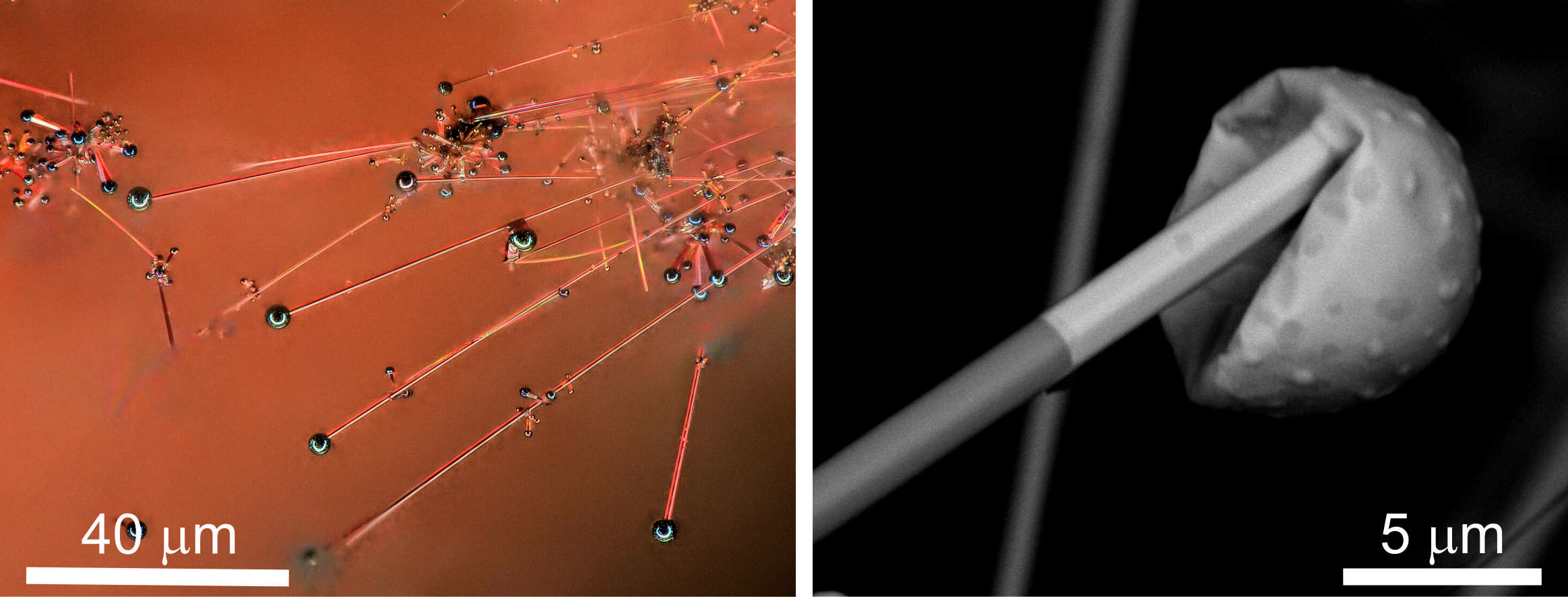
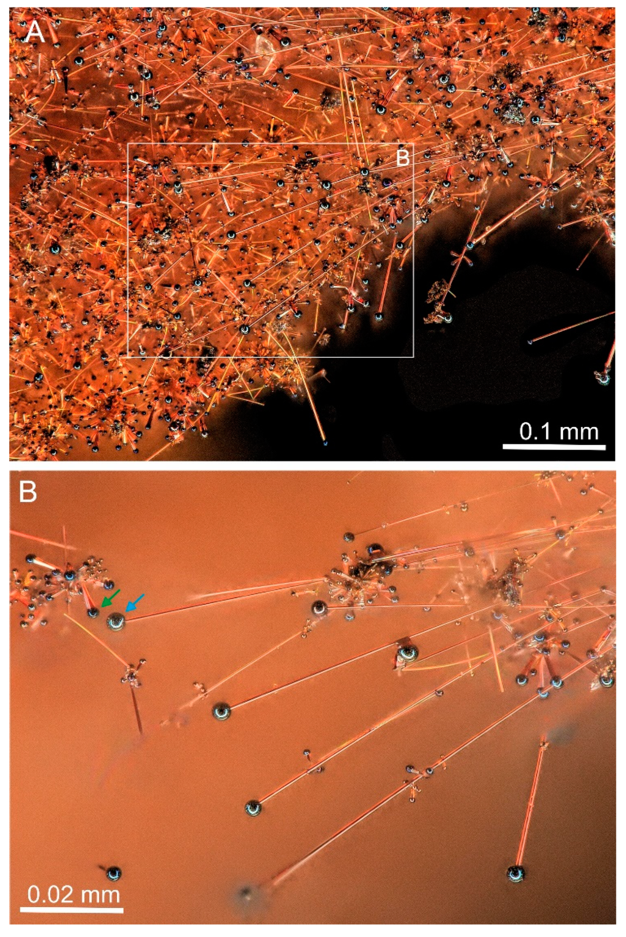
Samples containing orange crusts with a few mm
2 area were collected on a burned coal dump near Bytom town in the Upper Silesia, Poland (
Figure 1). These crusts are represented by greenockite, CdS, which forms various morphological types, among which rods, wires, and whiskers [
1] with bismuth drops on crystal tops are predominant (
Figure 2).
These morphological forms allow an assumption of their formation according to the VLS (vapor–liquid–solid) mechanism, a required condition of which is a presence of a metallic drop (catalyst) on the crystal top for support of its growth. For the first time, this mechanism was proposed by Wagner and Eliis in 1964 [
2], and at present, it is widely used for the synthesis of anisometric needle-like and fiber crystals of a nanometric size [
3,
4,
5,
6,
7].
In this paper, we present data on the morphology and composition of whisker and wire forms of greenockite from a burned coal dump near Bytom town, Upper Silesia, Poland, and discuss the mechanisms of their formation. Additionally, we describe the effects of cooperative growth of whiskers, and the unusual phenomena taking place in the catalyst drops induced by an electron beam of a scanning electron microscope.
Whiskers that are formed by the VLS mechanism have rarely been observed in nature and less so in burning coal dumps, mostly because of their bad preservation in secondary geological processes. The VLS growth mechanism was assumed for needle-like crystals of gersdorfite, NiAsS, from the arsenide ore of Schneeberg, Germany [
8] and for zincite, ZnO, from cavities in gabbro-syenites of the Сhatkal Range, Uzbekistan [
9]. Only a few examples of needle-like crystals from burned coal dumps, the formation of which is linked with VLS mechanism, have been mentioned in the literature: Germanium sulfide, GeS
2 (catalyst drop S + Ge) from the burned dumps of anthracite granulate from Foretville, Pennsylvania, USA [
10,
11] and greenockite (catalyst drop Bi + Te) from coal dumps in the Czech Republic [
12,
13,
14].
During World War II, radar installations often inexplicably failed. It turned out that long metal hairs appeared on the tin solder, which caused short circuits. These metal fibers were called whiskers. Cadmium and tin whiskers were first described in the late 1940s in telephone sets [
15,
16]. At present, whiskers are defined as extremely elongated crystals in one direction [
17,
18], the morphology of which is not forced by crystallographic directions but by environmental conditions and the mechanism of mineral growth [
17]. In 1964, Wagner and Ellis proposed a whisker growth mechanism that did not require a screw dislocation; this is the VLS (vapor–liquid–solid) mechanism. In their work, they explained the growth of Si whiskers with a drop of liquid Au on the top of the crystal. The growth through the VLS mechanism can be divided into stages. In the first stage, gas components are transported and absorbed by the liquid catalyst. The next stage is provided for the diffusion of primary gas components and their crystallization at the crystal–liquid interface. Today, the concept of the VLS mechanism has been widely developed. Analogies of the VLS mechanism have been elaborated, such as VSS (vapor–solid–solid), VQS (vapor–quasiliquid–solid), and SLS (solution–liquid–solid) [
3,
4,
19,
20,
21,
22,
23,
24].
3. Methods
The morphology of the greenockite crystals and their semi-quantitative composition were studied using a scanning electron microscope: Phenom XL with an EDS (energy-dispersive X-ray spectrometer) detector and Philips XL 30 ESEM with an EDS (EDAX type Sapphire) (Institute of Earth Science, Faculty of Natural Sciences, University of Silesia, Katowice, Poland). Quantitative analysis of the chemical composition of greenockite crystals and the catalyst drop was carried out at the microprobe analyzer CAMECA SX100 (Polish Geological Institute, National Research Institute, Warsaw, Poland) at 15 kV and 20 nA, beam size ~1 μm. Lines and standards: PbMβ, galena; CdLα, SKα, CdS; BiMβ, Bi2Se3; ZnKα, ZnS; SbLα, InSb; SeLβ, ZnSe.
The Raman spectrum of greenockite was collected on a confocal Raman microscope WITec alpha 300R (Institute of Earth Science, Faculty of Natural Science, University of Silesia, Katowice, Poland) equipped with a 532-nm laser and a CCD camera operating at −61 °C. The Raman signal was fed to a monochromator with a gratification of 600 mm−1 using an optical fiber with a working diameter of 30 μm. The laser power on the sample was ~20 mW. The measurements were made at an integration time of 3 s with an accumulation of 20 scans and a resolution of 3 cm−1. The monochrome was calibrated on a silicon wafer using a Raman scattering line (520.7 cm−1).
X-ray powder diffraction data were obtained using a PANalytical X’Pert PRO MPD PW 3040/60 powder diffractometer and placing the sample on a silicon disk to reduce the background (Institute of Earth Science, Faculty of Natural Sciences, University of Silesia, Katowice, Poland). The diffractometer is equipped with a copper tube using Cu
Kα radiation and an X’Celerator detector. The X-ray powder diffraction data were refined in the HighScore + software of Panalytical (version 4.6) using the latest ICDD pattern database, PDF 4
+ (version 2014) and, incidentally, the ICSD pattern templates (version 3.5 from 2015). The unit cell parameters were refined using the Rietveld method [
25]. ICP-MS (inductively coupled plasma mass spectrometry) analyses were performed in the ACME Laboratory in Vancouver, BC, Canada. The measurements were carried out according to the AQ250_EXT procedure using a 0.5 g sample after modified aqua regia digestion (1:1:1 HNO
3:HCl:H
2O).
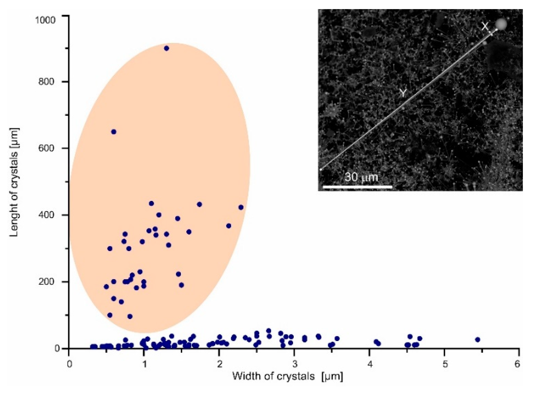
More than 200 images obtained from the scanning electron microscopes were used for measurement of the length and thickness of the anisometric crystals (rods, whiskers, and wires) and the catalyst drop diameter. The measurement results are presented in the plots (
Figure 4 and
Figure 5). Each point on the plot corresponds to one crystal, for which a measurement was performed.
4. Results
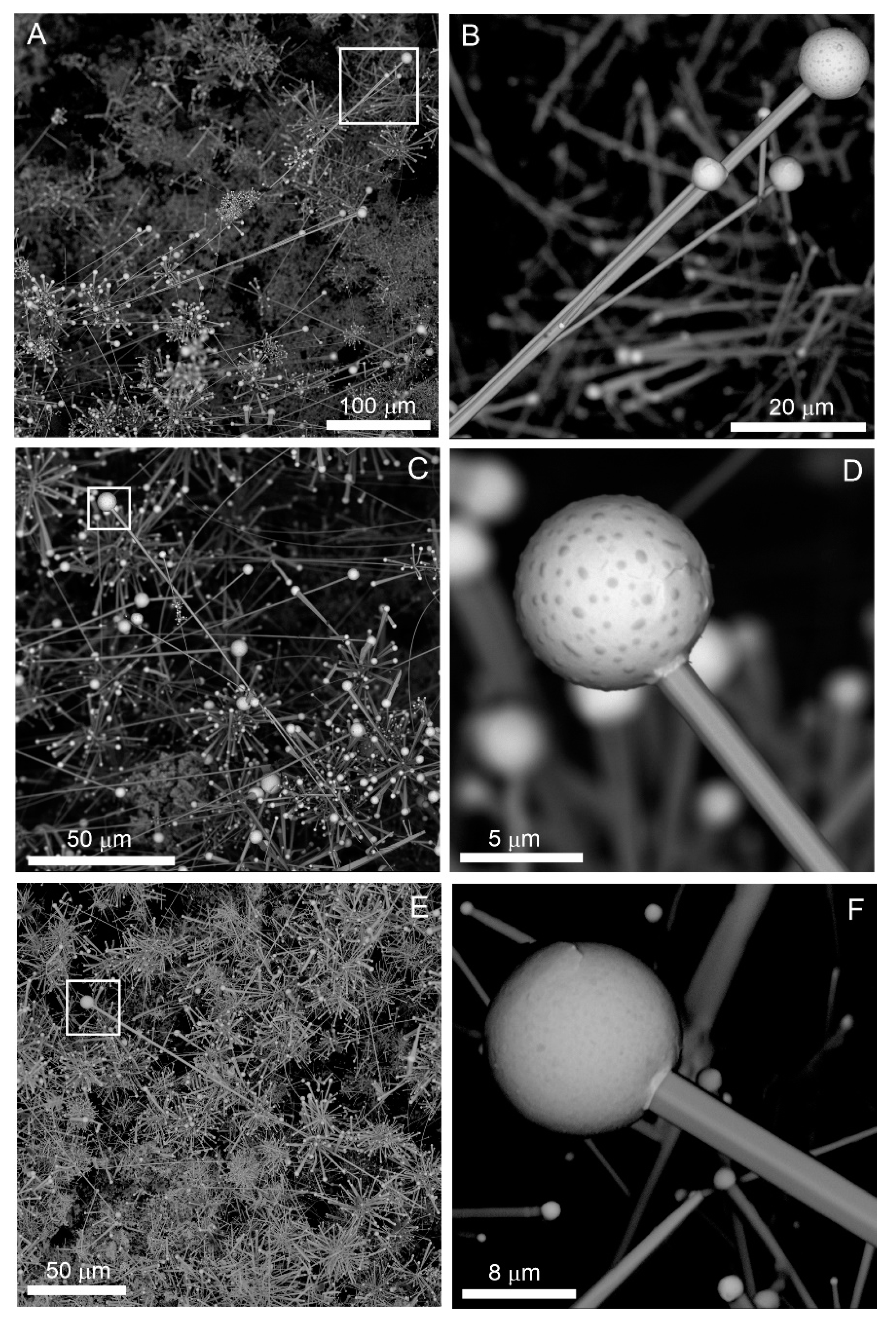
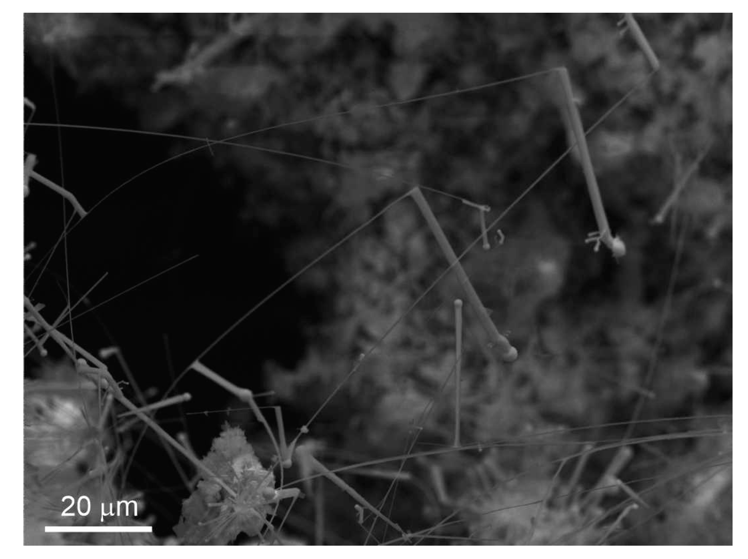
Around small gaseous channels in porous burned-out rocks, inhomogeneous greenockite mineralization is observed (
Figure 6 and
Figure 7A). The mineralization is formed mainly by fine non-stationary elongated forms, often with elements of a skeletal structure and bismuth drops (catalyst drop) on the top of these crystals.
Rare individual greenockite crystal, 0.5–3 μm in size, formed by prism {01–10}, pyramid {02–21}, and pedion {000–1} (
Figure 7B), and also splitting greenockite crystals of the two morphological types, sheaf-like (splitting of {01–10} prism,
Figure 7C) and “flower” type (splitting of (0001) or (000–1) faces (
Figure 7D), are noted.
Strongly anisotropic linear “one-dimensional” forms, including greenockite rods, whiskers, and wires, which were the main objects of this investigation, occur only in relatively thick orange greenockite crusts having a two-level structure (
Figure 1,
Figure 2 and
Figure 8A). Greenockite rods, oriented sub-perpendicular to the substrate, grow on a porous aggregate of burnt-out coal relics, dolomite, iron oxides, and alumosilicate fragments (
Figure 8A,B).
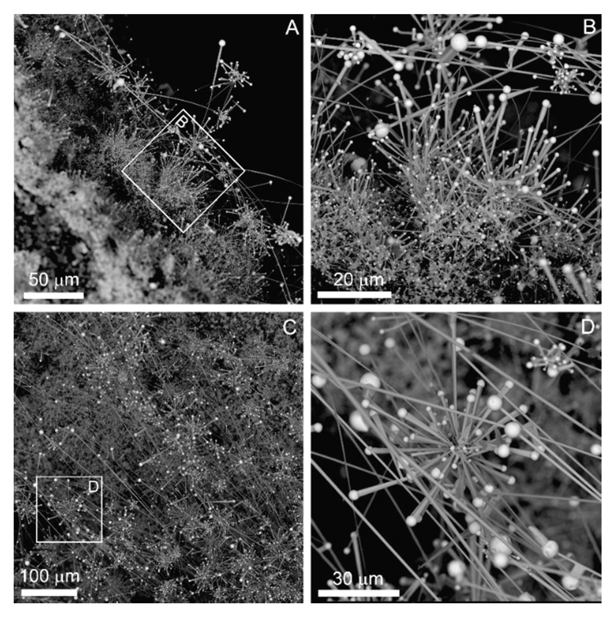
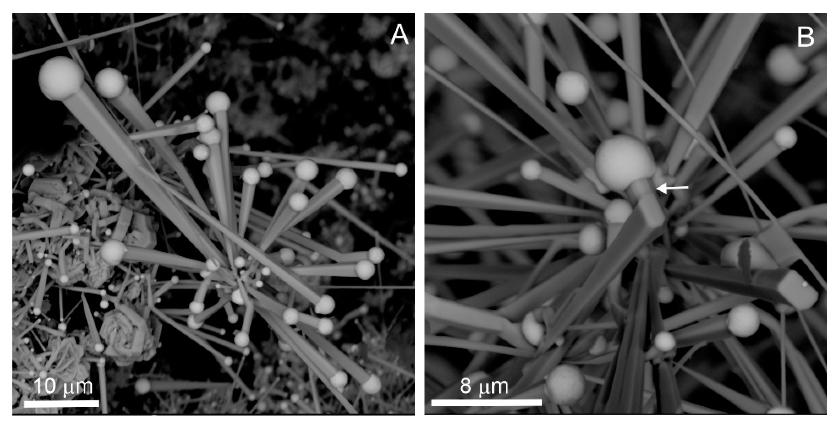
Rods often form radiating aggregate growing from one point (
Figure 9A). The rod thickness reaches 5–6 μm and about 10 μm in length (
Figure 4 and
Figure 9). The catalyst bismuth drop has a diameter comparable to the rod thickness and the rod to drop diameter ratio is usually less than 1.5 (
Figure 5). Relatively fine rods less than 1 μm in thickness have a rounded cross-section, whereas bigger ones have well-marked faces and exhibit a tendency for an increased thickness towards the catalyst drop (
Figure 9A). A cross-section of such thick rods is rectangular, which by the analogy of synthetic greenockite whiskers [
5,
6,
7,
20] allows confirmation that they are elongated along [01–10] and facetted by faces close to pyramid {2–120} and pedions {0001} and {000–1} (
Figure 9A,B). the edges of such crystals are often cut off by the micro-faces of a hexagonal pyramid (
Figure 9). It is rare that a change of the rod growth direction can be observed, which is accompanied by a change of the cross-section to hexagonal, i.e., growth comes in the direction [0001] (
Figure 9B).
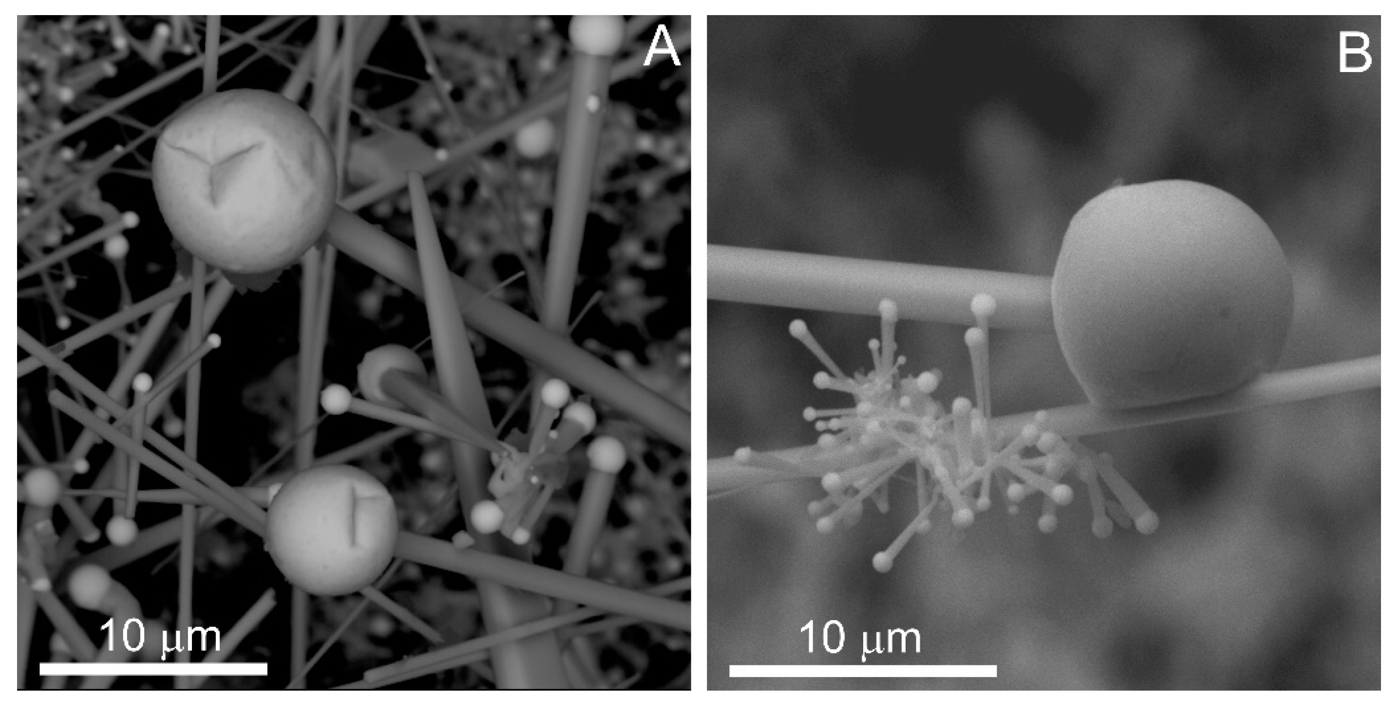
It is rare that rods exhibit evidence of morphology changes reflected in the specific character of their crystal growth. Faces with an inhomogeneous skeletal structure were noted, whereas the near-edge area of these faces are smooth and the central part is strongly rough (
Figure 10A,B). Peculiar intermediate non-facetted zones between the bismuth drop and crystal top are often observed (
Figure 10C,F), which probably is connected with a decrease of the catalyst drop diameter. In the rare case, we observed a formation of rods of the second generation elongated along the [01–10] “mother rod”, which has a different morphology depending on the growth direction on [0001] or [000,1] (
Figure 10D). Sometimes, the diameter changes of the second-generation rods elongated on [0001] are noted (
Figure 10E). Such diameter variations are non-synchronic and rather connected with changes of the bismuth drop diameter during growth.
The second level of greenockite crust is presented by fiber forms, which are sub-parallel to the substrate surface, and are visible both in the optical (
Figure 1 and
Figure 2) and BSE images (
Figure 8A,C). The thickness of these forms is usually less than 2 μm, and the length can be close to 1 mm (
Figure 4). The bismuth drop diameter can be in large excess over the fiber thickness (
Figure 5). Fibers of this type (especially at the early stage of growth) exhibit higher flexibility; their growth began the same as rods in the direction perpendicular to the substrate, and then fibers curve and set on greenockite rod aggregates of the first level (
Figure 8A).
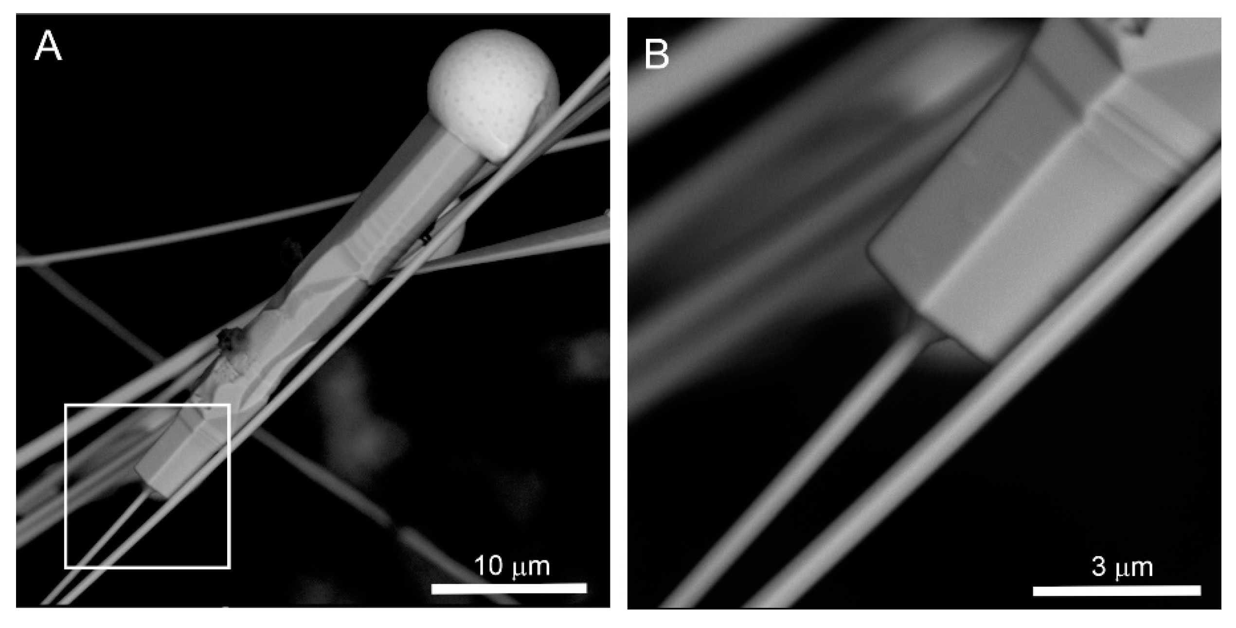
There are two extreme morphological types, which we conditionally called whiskers and wires. Whiskers are usually low curved and are more than 1 μm in thickness and some hundreds of μm in length and exhibit a faceted side surface and hexagonal cross-section (
Figure 11). Similar in morphology, thinner CdS whiskers were obtained in an experiment. They were studied under a transmission electron microscope, and it was established that the growth of these whiskers came in the [0001] direction [
5,
6,
20,
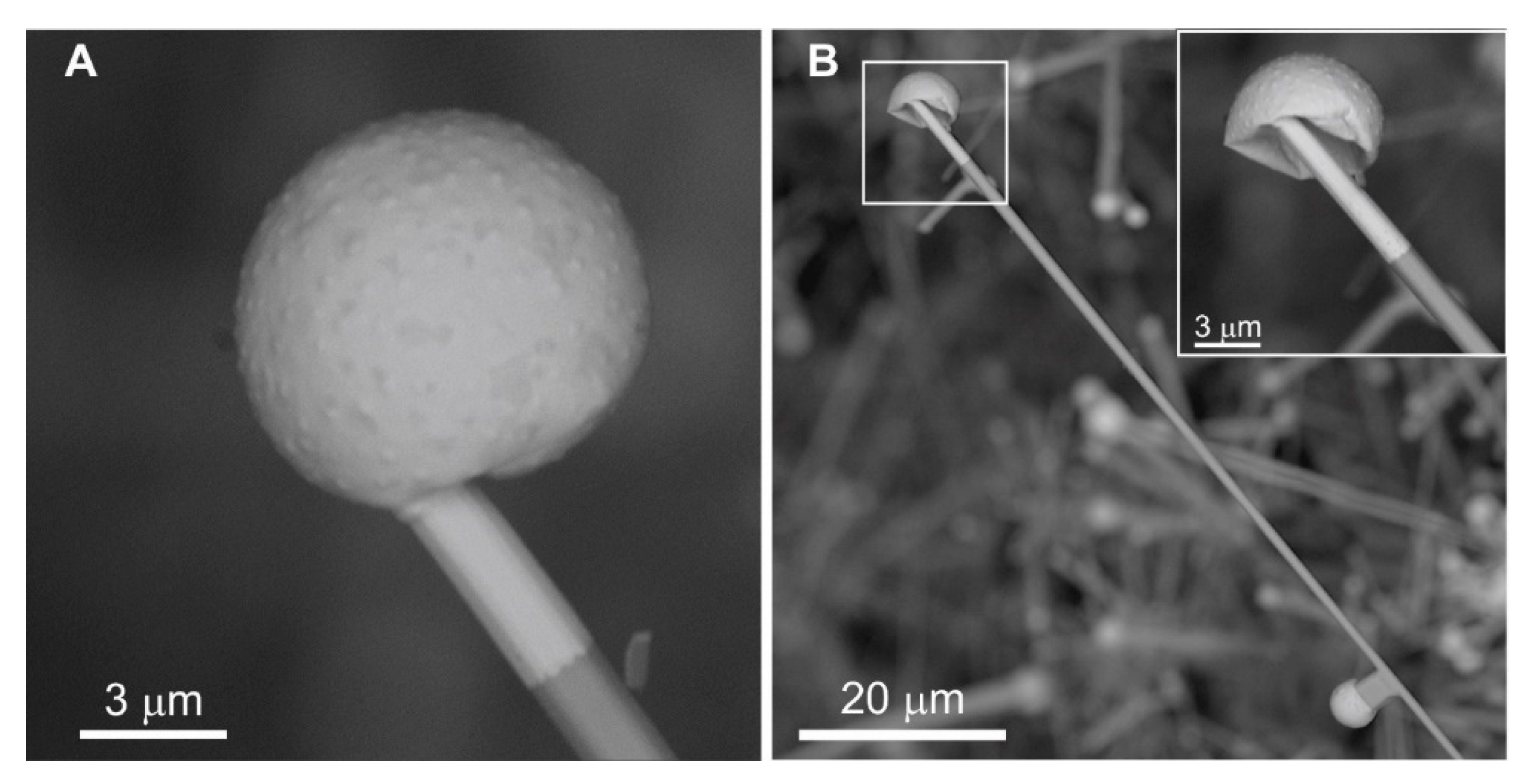
26]. Whiskers have a relatively big catalyst drop with an inhomogeneous surface (
Figure 2B). The drop surface has cracks and is deformed (
Figure 2B and
Figure 11,
Figure 12 and
Figure 13). Radiating aggregates of rods of the second generation are noted on whiskers (
Figure 8C,
Figure 10A,C,E and
Figure 12B).
Wires are nanoforms and have a diameter lesser than 1 μm and several hundreds of μm in length, and, as well as whiskers, they are elongated on [0001] (
Figure 14). This is confirmed by rare findings of wires with facetted top forms of the hexagonal cross-section (
Figure 15). Wires are easily curved and interlaced. The catalyst drop diameter on the tops of these wires often exceeds their thickness by 5–6 times. Wires have a rounded cross-section and are often linked to each other by perpendicular rods through a common catalyst drop (
Figure 14B,D,F).
Figure 16 demonstrates a rare case when the wires are [01–10] oriented after kinking from the original [0001] growth direction. The different growth directions cause changes of the morphological type from wires to rods and this kinking is synchronic in neighboring wires. It is a known phenomenon in nanotechnology and the change of the growth direction occurs towards the higher temperature area [
27,
28].
In a few cases, whiskers-wires were found, on which the thinnest plate hexagonal greenockite crystals overgrew (
Figure 17).
The composition of whiskers and wires was studied using SEM equipped with EDS. The composition of rods with bismuth drops was measured using a microprobe analyzer in polished mounts. Greenockite rods show a relatively stable composition (
Table 1) with impurities of Se (up to 4.11 wt.%), Zn (up to 0.67 wt.%), Pb (up to 1.47 wt.%), and Bi (up to 1.63 wt.%). In one of the analyses of the greenockite rod, the Bi content reaches 8.9 wt.% (
Table 1, analysis 9). Sb impurity is detected in two analyses (
Table 1, analyses 7 and 9).
Generally, the following regularities are noted according to EDS data:
- (1)
Idiomorphic and splitting greenockite crystals (
Figure 7B,C) show a composition close to ideal: Cd(S
0.99Se
0.01).
- (2)
Non-stationary short-prismatic forms with bismuth drops on the top (
Figure 6B and
Figure 7A) are greater than other types enriched in Se–Cd(S
0.88Se
0.12).
- (3)
Well-shaped rods (
Figure 9) show the following average composition: Cd(S
0.97Se
0.03).
- (4)
Whiskers (
Figure 11) correspond to the average composition Cd(S
0.95Se
0.05) and small Bi impurities are detected within.
- (5)
Wires (
Figure 14) show an average composition ~Cd(S
0.93Se
0.07), and flattened rods on them are close by composition to ~Cd(S
0.94S
0.06).
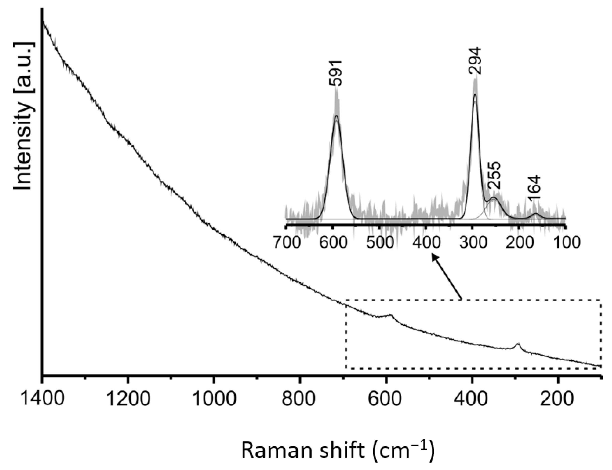
The Raman spectrum was measured on rod greenockite crystal (
Figure 18). The character of the Raman spectrum of CdS is strongly dependent on the grain size, its thickness, and crystallization degree [
29]. The spectrum shape in the TO–LO range (600–290 cm
−1) of the “bulk” structure and microcrystals differ significantly in the frequency of bands [
30,
31,
32]. Due to this, we can conclude that our spectrum was performed on a microsize crystal of the hexagonal system [
31,
32]. The band at 294 cm
−1 corresponds to LO A
1 and LO E
1 vibrations, and the band at 591 cm
−1 is related to their first overtones [
29,
31,
32,
33,
34]. The band at 255 cm
−1 is attributed to E
2 vibration, which does not change the frequency depending on the studied crystal size. A weak band at 164 cm
−1 can be attributed to the vibration of sulfur [
35]. Some authors attribute bands at low frequencies to acoustic vibrations [
34,
36].
To confirm the structure of the studied crystals, an X-ray powder diffraction analysis was performed (
Figure 19). The sample contained greenockite (26.3%), quartz (36.9%), and minor amounts of the next minerals: Hematite, sanidine, epsomite, and anhydrite. Powder XRD studies confirm a hexagonal structure of greenockite. The obtained unit cell parameters present as follows: a = 4.13538 (4) Å, b = 4.13538 (4) Å, c = 6.71298 (6) Å,
α = 90°,
β = 90°,
γ = 120°, and they are slightly bigger than those given in the literature [
37].
Bismuth drops on whiskers have a “knobby” shagreen surface and inhomogeneous composition. In some spots, these “knobbles” are enriched in S and Cd (
Figure 11D), and rarely in Pb, Sb, and As. We did not detect tellurium, described earlier in bismuth drops on greenockite crystals from coal dumps in the Czech Republic [
12,
13,
14]. We were unable to obtain more precise data on the composition of the drop surface because of their small size. The drops were destroyed as a result of our attempts to perform elemental X-ray mapping (see explanation below).
The chemical composition of relatively big catalyst drops on rods composed of metal bismuth is characterized by a considerable variation of impurities (
Table 2, wt.%): Cd 1.25–11.05; Pb 0–15.42; Sb 2.83–6.50; and S 0.98–2.90.
ICP-MS analyses of the crystal aggregate (B1) and substrate (B2) were performed (
Table 3). Probe B1 in comparison with probe B2 is characterized by enrichment in the following elements: Cd, Se, Bi, Pb, As, and Te, and depletion in Ba, Mg, Al, Ca, Mo, Fe, and Cu. The sulfur content in both probes is similar. The ICP-MS results were compared with data given in the literature for coal from the northern part of the Upper Silesian Coal Basin; these data are presented in
Table 3. We cannot compare the contents of all elements, given for our analyses, because the literature data is represented by a limited number of measured elements. High contents of elements in the analyses performed for our probes are bolded in
Table 3.
Catalyst Drop Behavior under Electron Beam Affect
Catalyst drops, being on the tops of thin whiskers (drop diameter to whisker thickness ratio > 5), began to change their form dynamically (bulges appear in different areas of drop) and exploded with spraying bismuth (which decorates whisker top) under the electron beam effect, which had some higher parameters in comparison to the standard conditions in an SEM chamber (an insignificant increase of spot and/or accelerating voltage) (
Figure 20). The two-second effect by the electron beam of 25 kV on the catalyst drop (
Figure 20A) led to change of its surface, which was reflected in the appearance of lighter spots, represented by practically pure bismuth, and grey spots enriched in Cd and S (
Figure 20B). Besides, on the top of the whisker in contact with the Bi drop, a thin film of bismuth is observed (
Figure 20B). the continued effect by the beam during five seconds led to an explosion of the drop and covering by bismuth near the top part of the whisker and neighboring greenockite crystal (
Figure 20C). The drop shell convolved around the crystal but did not melt down.
We repeated a similar experiment on the next few crystals and received an effect of a “deflated balloon” hanging on the whisker top covered by a new-formed nano-film of bismuth for the length of 10–20 μm (
Figure 20D–F). It is interesting that the whisker, having a visible crack on the drop surface, shown in
Figure 13A, also exploded, sputtering both relatively big bismuth drops up to 1 μm in size, and nanometric drops, which decorated the surrounding crystals (
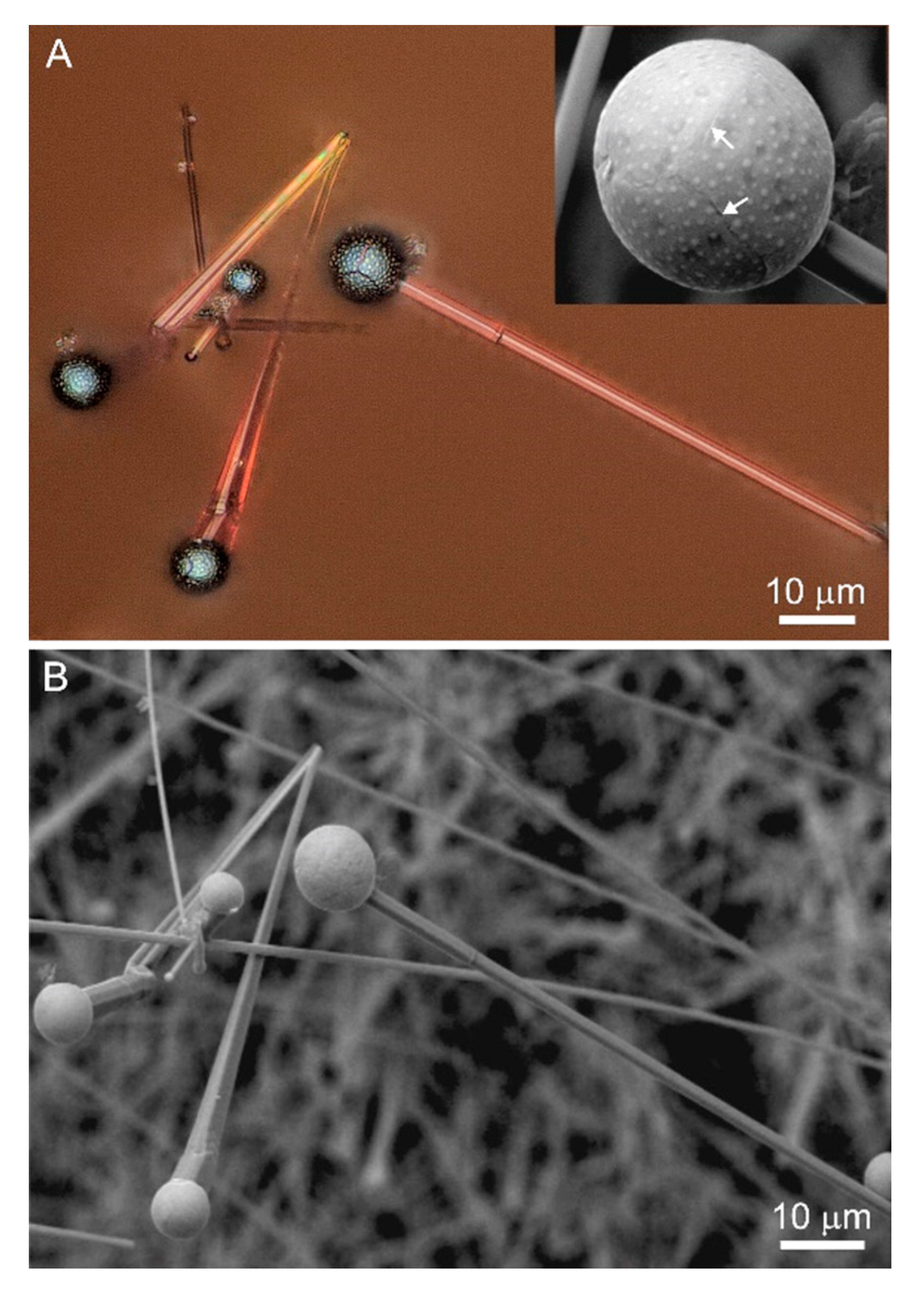
Figure 20F). If the exploded drop is close to the facceted greenockite crystal, then crystal will be decorated by small drops along on the edges, this phenomenon is called as the “Lemmlein’s dew effect” (
Figure 21A) [
39]. Interestingly, this similar decoration by nano-drops took place during greenockite fibers’ growth, which was accompanied by nano-fiber formation (
Figure 21B).
The description above indicates that the catalyst drop has a complex structure. It has a metal shell composed of bismuth, which is a few hundred nm thick, and its internal part is filled in substance with a relatively low melting temperature with respect to the bismuth shell.
We were able to receive an image of the drop before its explosion (
Figure 22). The drop sharply increases its volume to 15–20%, which was connected with gas emission from the liquid phase inside the drop. In one case, during the electron beam’s influence on the catalyst drop, it exploded and a dark phase remained (shown in the BSE image,
Figure 23) with a high carbon content at the internal side of the drop shell.
We also checked the behavior of a relatively homogenous Bi catalyst drop on short rod crystal under an 25 kV electron beam. We were not able to melt this drop, and only grey fragments enriched in sulfur and cadmium appeared on its surface (
Figure 24).
5. Discussion
Greenockite has specific pyramidal crystals (
Figure 7B) reflecting the character of its polar structure (absent of center of inversion, [
40,
41]). Greenockite crystals differ by the pedion faces’ character: (0001) has common edges with the hexagonal pyramid and small square (down to wedge-shaped crystal), it is responding to the direction of the highest crystal growth rate, and its shape depends on this rate (
Figure 7B) [
6]; (000–1) is well developed on greenockite crystals, forms edges with the hexagonal prism, and is responding to the direction of slower crystal growth in comparison with the opposite direction. Thus, the most favorable growth direction of filamentous and needle-like forms of greenockite is [0001].
All morphological types of greenockite from Bytom formed within a short period when fumarole was active. At the beginning of the fumarole activity at 500–600 °C, nano- and microcrystals of greenockite formed from gas. As a result of the temperature reduction, drops of liquid bismuth formed on the burned-out substrate (
Figure 14A). The contact of these drops with previously formed greenockite crystals may arise in conditions for the initiation of the VLS mechanism. Rods grow along the [01–10] direction, their length usually does not exceed several dozen microns (
Figure 4), and they form the first level of the orange greenockite crust (
Figure 8A). Whiskers and wires (axial forms) grow along the [0001] direction, which is determined on its morphology (
Figure 11 and
Figure 15). Their length may approach 1 mm and their thickness is 100 times smaller than the length (
Figure 4,
Figure 8, and
Figure 14). They are usually placed sub-parallel to the substrate and lie on the radiating aggregate of rod crystals forming a specific second level (
Figure 2 and
Figure 8A,C). Greenockite whisker and wire growth began growth perpendicular to the substrate as well as rods, but due to the catalyst drop weight, the heat transfer direction, and their high flexibility they curve and lie sub-parallel to the substrate surface (
Figure 2 and
Figure 8A). There are two types of fiber axial forms: facetted linear whiskers several dozen hundred μm in length and few μm in thickness, and wires—more than 100 μm in length and less than 0.5 μm in thickness (
Figure 11 and
Figure 14). Whiskers possess {01–10} hexagonal prism faces, whereas nanowires exhibit rounded surface (
Figure 11F,
Figure 14B and
Figure 15B). Perpendicular flattened branches elongated on [01–10] are noted on wires (
Figure 14B,D,F), the morphology of these branches corresponds to the rod morphology (
Figure 9). If our proposition as to orientation is right, then rods exhibit faces close to the plane of second hexagonal prism {−12–10} and pedion faces (0001) and (000–1). In
Figure 10D it is well visible how parallel branches of the second generation of greenockite are growing on the “mother rod”: quick growth of the thin crystal in the direction [0001] and slow in the direction [000,1]. Also, the possibility cannot be excluded that some rods grow in the direction perpendicular to faces of the second hexagonal prism [−12–10] (i.e., growth by micro-face-edges of {01–10} prism), then in faceting of rods, two parallel faces of hexagonal prism {01–10} and monoedrs (0001) and (000–1) will take part. Edges between the base faces of rods with rectangular cross-section are complicated by appearing of pyramid faces, which leads to the octagonal form cross-section (
Figure 9 and
Figure 10F).
Position of different morphological types of greenockite fibers and rods in aggregates indicated their simultaneous growth: the relatively short crystal formed on [01–10], and whiskers and nanowires–on [0001]. Formation of fiber crystals was connected with the period of fumarole activity at relatively stable conditions, which nevertheless can be locally changed, for example, by a sudden gust of wind, appearance of the new gaseous channel, and so on. So, the growth of flattened greenockite crystals on whisker, as crystals formed directly from the gas, and kinking of wires (
Figure 16 and
Figure 17) are rather associated with local temperature increase [
27,
28].
At the beginning of fumarole formation diverse small greenockite crystals, which worked as seeds (substrate) for fiber crystals, grew from gas. Interestingly, these bismuth drops, which hit to the substrate without greenockite crystals, did not generate greenockite fibers (
Figure 14E). Fibers formed at temperatures lower than greenockite crystals forming from gas. The presence of bismuth drops on the tops of growing crystals points out its growth by the VLS mechanism. Bismuth drop diameter on rod tops is insignificantly larger than a crystal thickness (
Figure 5) as it usually is at such mechanism [
3,
4,
19,
20,
42]. We were not able to melt bismuth drops on rods under the 25kV electron beam (
Figure 24). Catalyst drops on rods have an inhomogeneous composition with significant variations of Cd, Pb, S, Sb impurities content (
Table 2), which can decrease a melting point of eutectic mixture of metals [
43]. We consider that rod growth occurred at a temperature higher than 270 °C (melting point of pure bismuth, [
44]) in areas of hot gas efflux. Greenockite crystals, formed from the gaseous phase at temperatures of 500–600 °C, close to the maximal measured at fire foci, are different due to the low Se content in comparison to crystals formed by the VLS mechanism. Together with rods, the relatively quick growth of whiskers and wires, for which the characteristic feature is the presence of a relatively big catalyst drop, occurred, the diameter of which exceeded the crystal thickness several times (
Figure 5). Under the minor heating of the electron beam, the metallic Bi shell of the catalyst drop becomes elastic, and a filling substance transfers to the liquid state (probably together with the gas emission) (
Figure 22). Whiskers and wires grow above the substrate (at the second level of the crust) at a relatively low temperature in the heterogeneous atmosphere of combustion products. Among the products, there are various chemical compounds, such as atoms and molecules of different gases, molecular complexes (possibly with organic components), and also nanodrops and nanoparticles, which transport both the Cd and S necessary for greenockite crystallization, and other chemical substances influenced the eutectic point of the catalyst mixture. Whiskers; and wires’ growth is very fast [
3,
4,
6]. It is limited in space only by a few-millimeter zone under the fumarole (gas channel), where there is no significant impact of the environment. Besides, kinetic factors [
45] and cooperative effects influence the growth of individual fiber greenockite crystals.
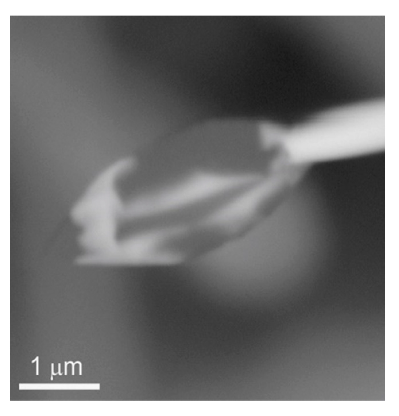
Fiber crystals grow almost immediately above the substrate, sorbing gaseous components on the surface of the catalyst drop, which are necessary for crystal growth. Our experiments of heating catalyst drops on whisker tops allow the suggestion that the gas kept inside escapes during the experiment from the inside of the catalyst drop (
Figure 20,
Figure 21,
Figure 22 and
Figure 23). This effect of an “air-balloon” sharply increases the active area of the catalyst drop and as a result, influences the growth rate of whiskers and wires. Part of the drops lost gas (possibly in the SEM chamber), which is reflected in the appearance of the catalyst drop form resembling a “rotten apple” (
Figure 12A). Moreover, in the room conditions, the filling substances in catalyst drops are in the solid state as these drops can have cracks and preserve their shape (
Figure 13A).
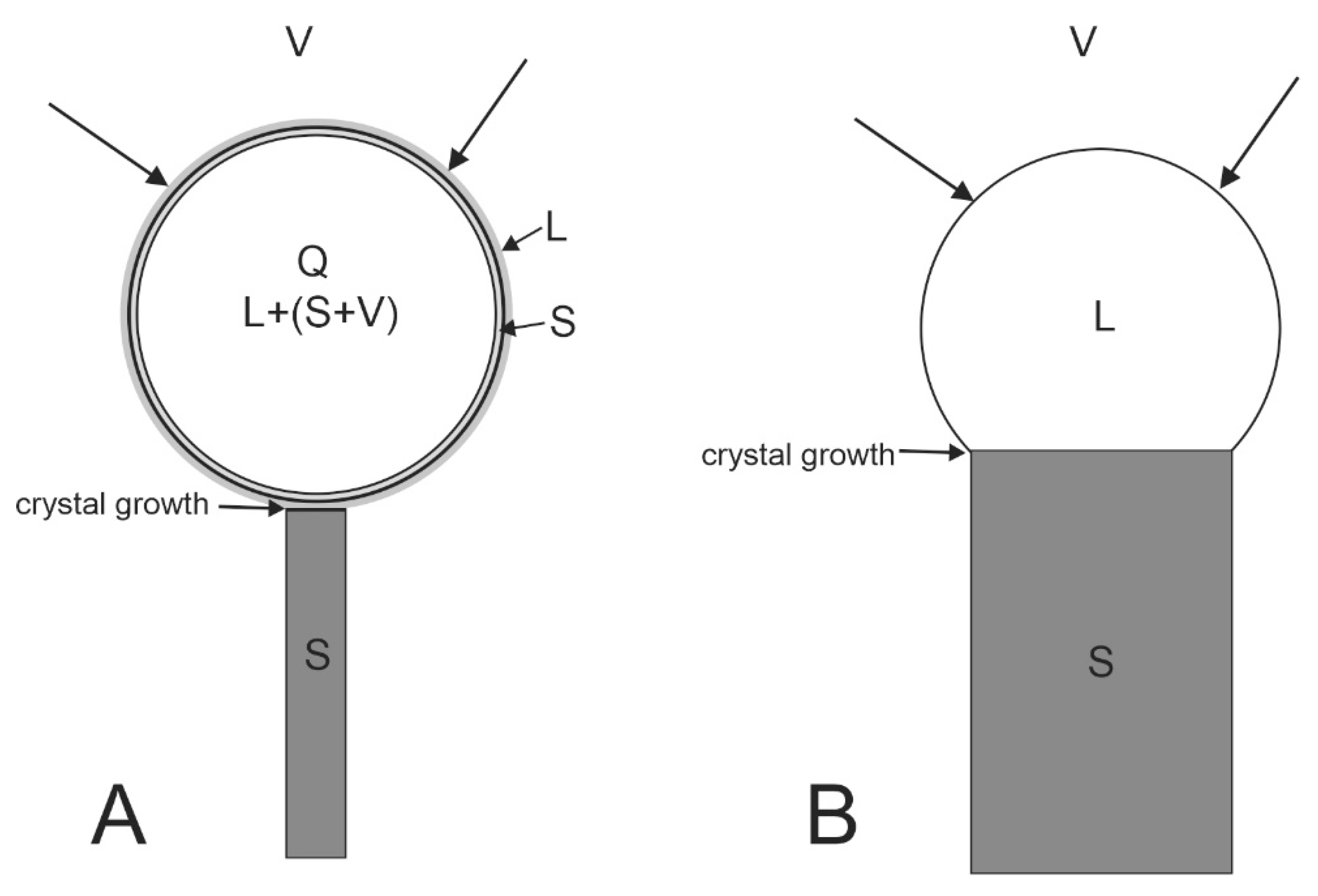
We consider that whiskers and wires formed at a lower temperature than rods, possibly even lower than 200 °C. In this case, the growth mechanism of greenockite whiskers and wires was more complicated than the VLS mechanism and it was close to the mechanism of fiber crystal growth called the VQS mechanism in which the liquid phase has an inhomogeneous composition and contains solid particles (Q-quasi-liquid) [
4,
19]. In our case, a nanometric bismuth film of solid metal, which determined the shape stability of the catalyst, is formed on the liquid drop. By this layer, components of the whisker and wires are diffused to the drop–crystal interface. The droplet size is several times larger than the thickness of the whisker itself, which creates good conditions for surface diffusion (
Figure 25) [
4,
19,
20,
46].
However, when wire growth sharply stopped, specific effects are observed. In
Figure 26, cases of wire growth braking are schematically shown as a result of the cooperative phenomena. The formation of flattened branches on the side area of the growing crystal is caused by contact of the catalyst drop of one wire with the face of another greenockite wire (
Figure 14B,D,F, and
Figure 25), and the growth of the provider of the drop is completely stopped. Braking of the wire growth on allogeneic obstacles is a rare phenomenon; in this case, the thickening and formation of faces at the near-top part of the wire is observed (
Figure 15 and
Figure 26III-b).


