Article

Detoxification of Arsenic-Containing Copper Smelting Dust by Electrochemical Advanced Oxidation Technology

1
School of Chemical Engineering, Zhengzhou University, Zhengzhou 450001, China
2
National Engineering Laboratory for Hydrometallurgical Cleaner Production Technology, Key Laboratory of Green Process and Engineering, Institute of Process Engineering, Chinese Academy of Sciences, Beijing 100190, China
3
Department of Materials Engineering, The University of British Columbia, Vancouver, BC V6T1Z4, Canada
4
Henan Province Industrial Technology Research Institute of Resources and Materials, Zhengzhou University, Zhengzhou 450001, China
*
Authors to whom correspondence should be addressed.
Minerals 2021, 11(12), 1311; https://doi.org/10.3390/min11121311
Submission received: 15 October 2021 / Revised: 21 November 2021 / Accepted: 22 November 2021 / Published: 24 November 2021

Abstract

:
A large amount of arsenic-containing solid waste is produced in the metallurgical process of heavy nonferrous metals (copper, lead, and zinc). The landfill disposal of these arsenic-containing solid waste will cause serious environmental problems and endanger people’s health. An electrochemical advanced oxidation experiment was carried out with the cathode modified by adding carbon black and polytetrafluoroethylene (PTFE) emulsion. The removal rate of arsenic using advanced electrochemical oxidation with the modified cathode in 75 g/L NaOH at 25 °C for 90 min reached 98.4%, which was significantly higher than 80.69% of the alkaline leaching arsenic removal process. The use of electrochemical advanced oxidation technology can efficiently deal with the problem of arsenic-containing toxic solid waste, considered as a cleaner and efficient method.

1. Introduction

The output of nonferrous metals is increasing by the year, and most of the heavy nonferrous metal concentrates contain arsenic. The arsenic in these heavy nonferrous metal minerals is mainly combined with copper, lead, zinc, and sulfur [1,2]. In the nonferrous metal metallurgical process, arsenic usually enters smoke, smelting residues, and acid in the form of waste slag, wastewater, and exhaust gas, respectively [3]. Compared with elemental arsenic, arsenic compounds are more toxic. Arsenic can enter the human body through air, water, and other ways, causing great harm to the human skin, digestive, and respiratory system [4]. Long-term exposure to arsenic substances can cause skin cancer, lung cancer, bladder cancer, and kidney cancer [5]. Tumor tissue analyses confirmed that it is one of the human carcinogens. Arsenic-containing copper smelting dust (ARCD) is a solid hazardous waste formed through processes such as copper smelting, converting, and anode slime smelting [6]. Arsenic mainly forms compounds with copper and sulfur in copper sulfide concentrates. During the copper smelting process, part of the arsenic will enter the copper smelting dust. If copper smelting dust is recycled directly to copper smelting without arsenic removal, arsenic will accumulate, reducing the main metallurgy production efficiency and affecting the entire smelting process [7]. Further, if the ARCD is not appropriately treated, it will have a more significant impact on the environment and human health.
The main methods for removing arsenic from arsenic-containing solid waste include alkaline leaching, acid leaching, and roasting. The alkaline leaching process mainly converts arsenic from solid waste residue to the liquid phase by alkali to realize the separation of arsenic from other metals [8,9,10]. The acid leaching process usually uses sulfuric acid and hydrochloric acid to leach the arsenic-containing material and then separates the arsenic from the arsenic-containing material through solid–liquid separation [11]. The roasting method mainly includes oxidation roasting, reduction roasting, and solidification calcination. The roasting arsenic removal process is used mainly to volatilize the arsenic in the form of arsenic trioxide at high temperatures to separate it from other valuable metals [12,13]. The As(III) in the solid waste is converted to As(V) into the liquid phase and then removed by precipitation, adsorption, or other methods [14,15,16,17]. Most of the arsenic in ARCD exists as As(III). Converting As(III) to As(V) can reduce its toxicity. The standard methods for oxidizing As(III) to As(V) include H2O2 oxidation, O3 oxidation, and others [18,19,20,21]. However, the oxidation of these oxidants may lead to the formation of toxic by-products, and the cost is relatively high. The electrochemical advanced oxidation technology is characterized by the generation of H2O2, hydroxyl radicals, active chlorine species with strong oxidizing ability, etc. [22]. The use of electrochemical advanced oxidation technology can be even more efficient and convenient for the oxidation of As(III) to As(V) [23,24,25].
The electrochemical advanced oxidation method mainly generates H2O2 in situ; namely, when the oxygen passes into the cathode, the H2O2 is in-situ generated through the two-electron oxygen reduction reaction (ORR) [26]. The H2O2 generated in situ at the cathode can reduce the transportation and storage costs of H2O2 during the reaction process, and the oxidation efficiency may increase [26]. Advanced electrochemical oxidation has the advantages of high efficiency, green environmental protection, and controllable process of oxidation method. This approach uses different electrode materials to generate oxidants. Compared with oxidation methods such as ozone oxidation, ultraviolet oxidation, and microwave oxidation catalysis, the electrochemical advanced oxidation method has the advantages of rapid reaction and simple operation and can generate active oxygen groups in situ for material oxidation. At present, the most widely used cathode materials are carbonaceous due to their high stability, corrosion resistance, and high conductivity. Carbonaceous materials mainly use graphite, carbon nanotubes, and carbon felt (CF). The carbon felt electrode has a porous structure conducive to the transmission of oxygen, causing higher in situ generation of H2O2 [27,28].
The modification of carbon felt can increase the electrochemical activity of the electrode and promote the generation of H2O2 by introducing active oxygen-containing groups on the surface. Treated with KOH firstly, then calcined at a high temperature, the oxygen-containing functional groups, the specific surface area, and the microporous structure of the carbon felt will be increased [29]. The surface of carbon felt is doped with nonmetallic elements, and the electrochemical performance of the electrode can be enhanced by doping with nonmetallic elements such as N, P, and S. After doping these nonmetal elements, the number of H2O2 produced can be increased, the secondary pollution in the electrochemical reaction can be reduced, and the pH range of electrochemical experiments can be expanded [30,31]. Metal materials have a strong electrical conductivity and catalytic activity, so the electrical conductivity and electrochemical performance of the electrode are enhanced by introducing metal ions. By introducing Fe, Cu, and other elements, the electrode gains higher electrochemical performance [32].
The carbon felt is modified by carbon black and PTFE [2]. Under the action of carbon black, the conductivity of the carbon felt electrode, the active sites of the reaction, and the electrochemical performance of the carbon felt cathode would be improved. The carbon felt electrode was characterized and analyzed using a scanning electron microscope, nitrogen adsorption–desorption test, and water contact angle. The modified carbon felt electrode was used to remove arsenic from the ARCD by electrochemical advanced oxidation method.

2. Experimental Procedures

2.1. Materials

The ARCD collected from Western Mining Group Co., Ltd. (Xining, China) was dried at 60 °C for 24 h, then it was crushed, ground, and sieved. The particle size of −74~+48 μm was selected as the experimental material. All chemicals used in this experiment were of analytical grade. The experimental water had high purity. The experimental carbon felt of Inner Mongolia Wanxing Carbon Co., Ltd., the carbon black of the US CABOT Cabot Black VXC-72, and the PTFE of Daikin Fluorochemicals (China) Co., Ltd. (Changshu, China) were used in the experiment.

2.2. Methods

The carbon felt was ultrasonically cleaned in a mixed solution of acetone, ethanol, and ultrapure water for 30 min and then dried in a vacuum drying oven at 60 °C for 24 h. The carbon felt sample was labeled as the original carbon felt. A certain proportion of PTFE emulsion (60%) and carbon black was mixed with 30 mL of ultrapure water and 1 mL of n-butanol and then ultrasonically mixed for 10 min. The carbon felt was immersed in the mixture and ultrasonicated for 30 min. The ultrasonic carbon felt was dried in a vacuum for 24 h. The dried carbon felt was calcined at 360 °C for 1 h. The calcined carbon felt was labeled as modified carbon felt.
The experiment was carried out in a 250 mL undivided three-electrode cell at 25 °C, and the temperature was controlled by an electrochemical workstation (PARSTAT 4000A). The original carbon felt and the modified carbon felt were used as the working electrode, the platinum sheet was used as the counter electrode, and the mercury-oxide mercury electrode was used as the reference electrode. The electrolyte was the NaOH solution with a concentration of 75 g/L. Before electrochemical experiments, oxygen was pumped into the solution for 30 min to saturate the oxygen in the electrolyte. The ARCD was added to the electrolyte at a concentration of 500 mg/L. The arsenic removal experiment was conducted at the condition of original carbon felt and modified carbon felt.
The arsenic in the leaching solution was removed by calcium salt, and Ca(OH)2 was added to an exact amount of 100 mL arsenic leaching solution. The mixed solution was placed in a constant temperature water bath at 65 °C for 2 h with the rotation speed of 300 r/min and then filtered by a water circulating vacuum pump. The filtrate was added 0.075 mol/L aluminum chloride as a flocculant in a constant temperature water bath for further arsenic removal [33,34]. The filtrate was stirred at a speed of 120 r/min for 5 min and then stirred at a speed of 80 r/min for 15 min. After the mixture was complete, the filtering operation was performed. Finally, the obtained final filtrate can be recycled for the leaching process after adjusting the concentration, and the final residue can be recycled for the copper smelting process.

2.3. Characterization and Analysis

The phases of ARCD were determined by X-ray diffraction (XRD, PANalytical Empyrean, Almelo, The Netherlands), and the chemical composition was determined by inductively coupled optical emission spectrometry (ICP-OES, PerkinElmer Optima 7300 V, Richmond, CA, USA). The carbon felt and modified carbon felt were characterized by a scanning electron microscope (SEM, FEI Quanta 250, Hillsboro, OH, USA) equipped with energy dispersive X-ray spectrometry (EDS, EDAX Genesis, Richmond, CA, USA). Further, its microscopic morphology, the specific surface area, and pore size distribution were measured by the BET with N2 adsorption and desorption analyzer. The hydrophilicity and hydrophobicity of the electrode surface were measured by a contact angle meter (Theta, Biolin, Espoo, Finland), and the pH value of the electrolyte was obtained using a pH meter.
The concentration of H2O2 generated in the electrolyte was measured with a double-beam UV-visible spectrophotometer using a potassium titanium oxalate developer. Electron spin resonance spectroscopy (ESR, Bruker EMX12, Karlsruhe, Germany) was used to measure the ·OH content in the electrolyte, and DMPO was added as a quencher for OH for comparison experiments.
The leaching efficiencies of the target metal were obtained as follows:
η = C A s ( solution ) · V C A s ( solid ) · M × 100 %
where CAs(solution) represents the As content in the solution, V represents the electrolyte volume, CAs(solid) corresponds to the arsenic content in the ARCD, and M is the content of the ARCD in the electrolyte.

3. Results and Discussion

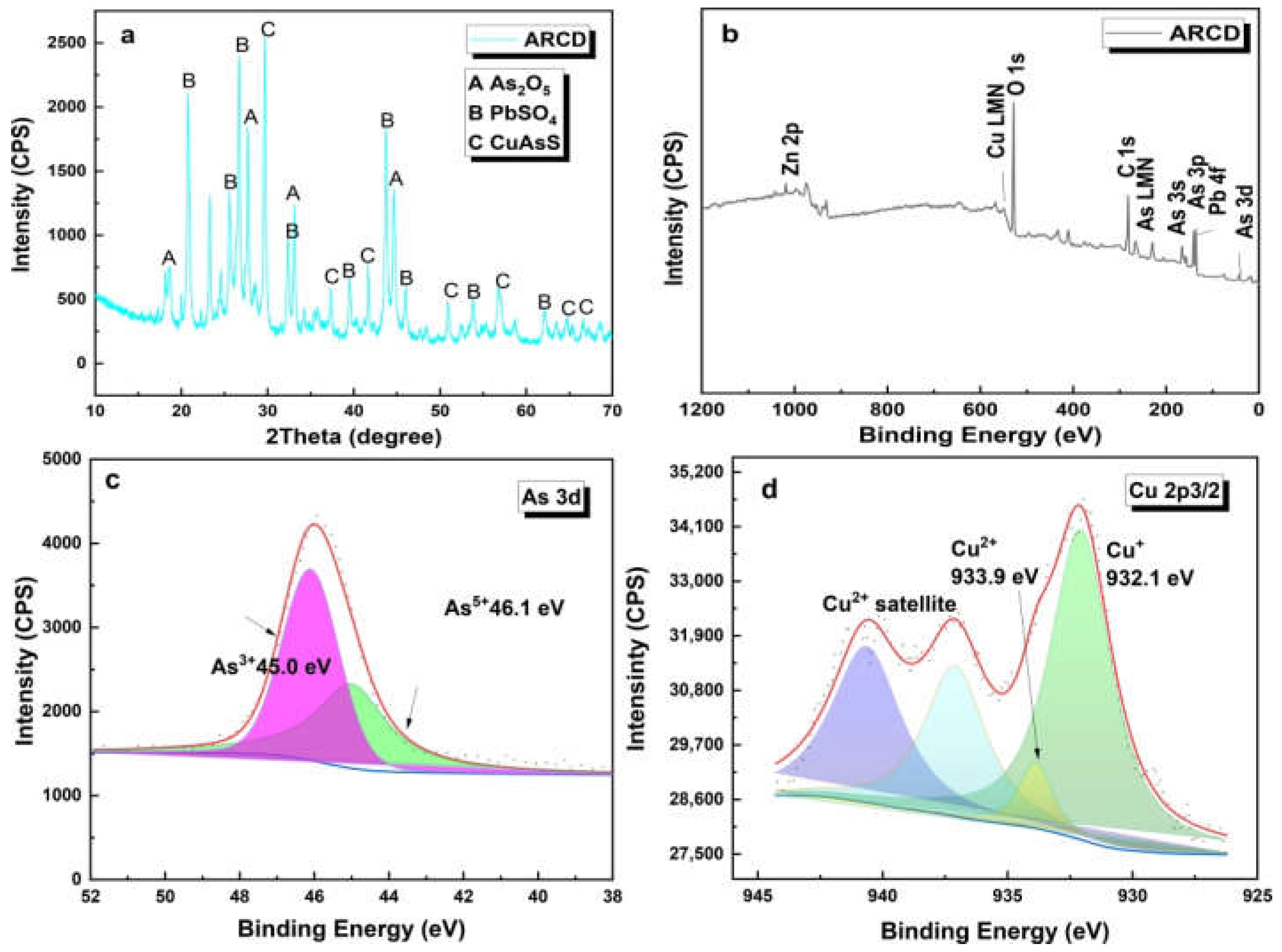
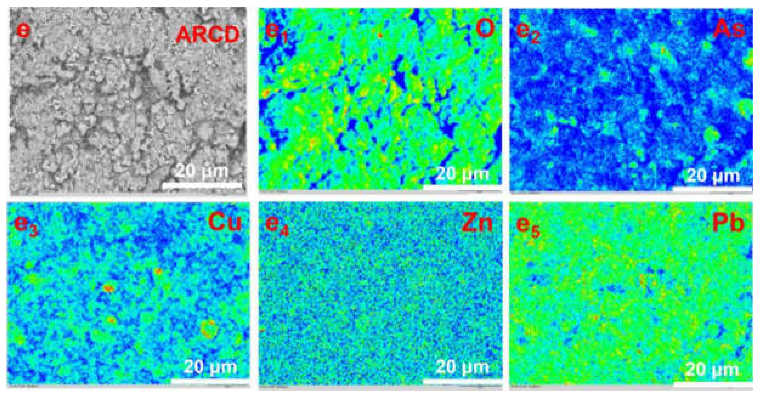
3.1. Characterization of the Spent Catalyst of the ARCD

The ARCD contains a variety of metal elements. As shown in Table 1, the content of As2O3 reaches 8.78%, and the content of CuO, ZnO, PbO, and Bi2O3 is 15.31%, 1.95%, 17.7%, and 6.62%, respectively. The XRD shows that the main phases in the smelting dust are As2O5, As2O3, and CuAsS. The XPS analysis shows that the primary forms of arsenic in the material are As(III) and As(V). The contents of As(V) and As(III) in the ARCD are 59% and 41%, respectively. As shown in Figure 1d, the copper in the ARCD mainly exists in Cu(I) and Cu(II). The ARCD was analyzed by SEM-EDS, which shows that As coexisted with Cu, Pb, and Zn.

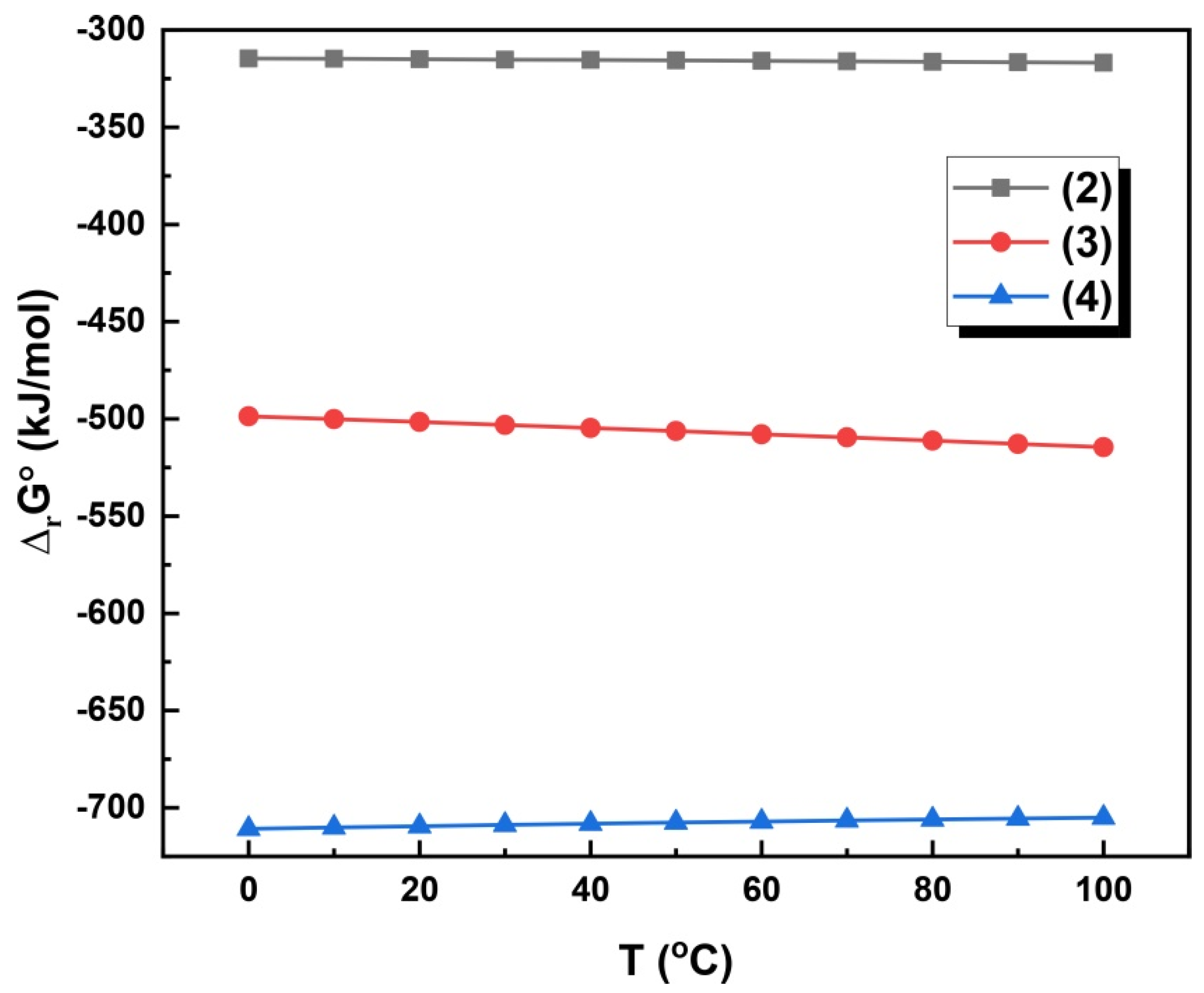
3.2. Alkaline Leaching Mechanisms

The arsenic in the ARCD was converted to arsenate by the NaOH leaching process and entered the liquid phase. The leaching process was mainly conducted according to the following (2)–(4) reactions. The thermodynamic analysis of the reaction shows that the reaction can be carried out at 10–100 °C. As can be seen from Figure 2, reactions (2)–(4) can be carried out under the experimental conditions.
As2O3 + 2NaOH = 2NaAsO2 + H2O
As2O3 + 6NaOH + O2 = 2Na3AsO4 + 3H2O
As2O5 + 6NaOH = 2Na3AsO4 + 3H2O
The Eh-pH diagram was used to analyze the thermodynamics of the elements in the leaching process of ARCD. Figure 3 shows the Eh—pH diagrams of As, Pb, Zn, and Cu, respectively. Arsenic exists in the form of As(s), HAsO2(aq), H2AsO3, HasO42−, and AsO43− under alkaline conditions. At higher pH and higher potential, H2AsO3 oxidized to AsO43− which shows that the As in the ARCD will enter the solution. Pb exists in the form of Pb2+, PbOH+, HPbO2−, and PbO(s) under alkaline conditions. Under higher pH conditions, Pb mainly exists in the form of HPbO2, which means Pb can dissolve in the alkaline solution. With the change of pH, Zn varies in the form of Zn(OH)2, HZnO2, and ZnO22−, and Zn could dissolve in the solution when the alkaline strength increases.

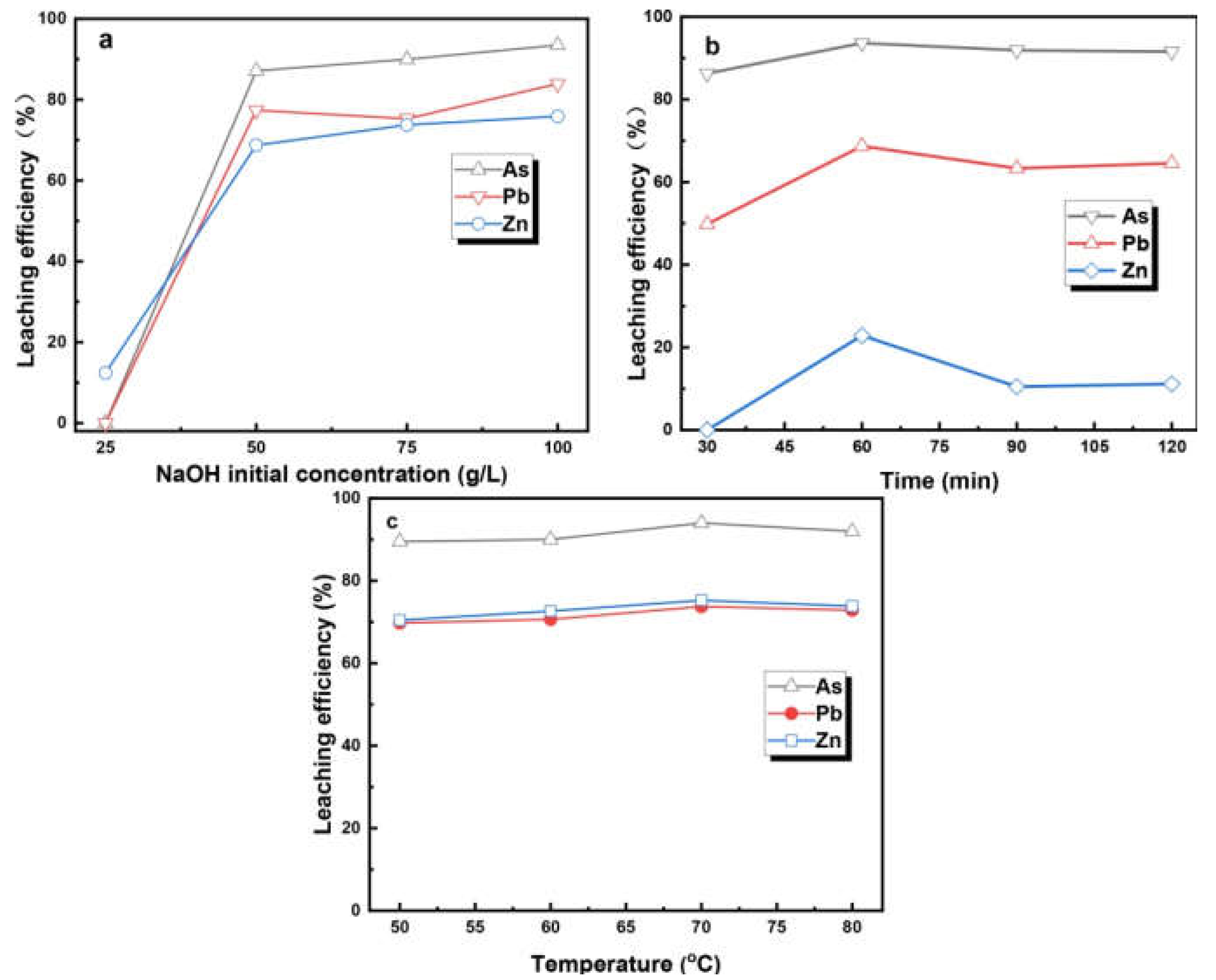
3.3. The Alkaline Leaching Process of the ARCD

The alkaline leaching process was optimized to increase the leaching rate of arsenic. The leaching rate of arsenic was optimized via varying the temperature, NaOH concentration, and time to finally obtain the optimum conditions, as can be seen from Figure 4; NaOH of 75 g/L, the temperature of 70 °C, and leaching time of 90 min. The arsenic removal rate from ARCD of 94% was obtained.
After alkaline leaching, the leaching residue was analyzed by XRD and XPS. Figure 5a,b shows that as the NaOH concentration increases, the peak intensity of arsenic decreases until it finally disappears. At the same time, Cu(OH)2 phase was found in the slag, which indicates that Cu(OH)2 is formed after NaOH leaching and remains in the slag. The XPS shows that the arsenic in the ARCD exists in the form of trivalent and pentavalent. Figure 5d indicates that, after alkaline leaching, arsenic exists in the trivalent form in the leaching residue. This means that this part of trivalent arsenic needs to be removed by the oxidation leaching process.

3.4. Electrochemical Advanced Oxidation Treatment of ARCD

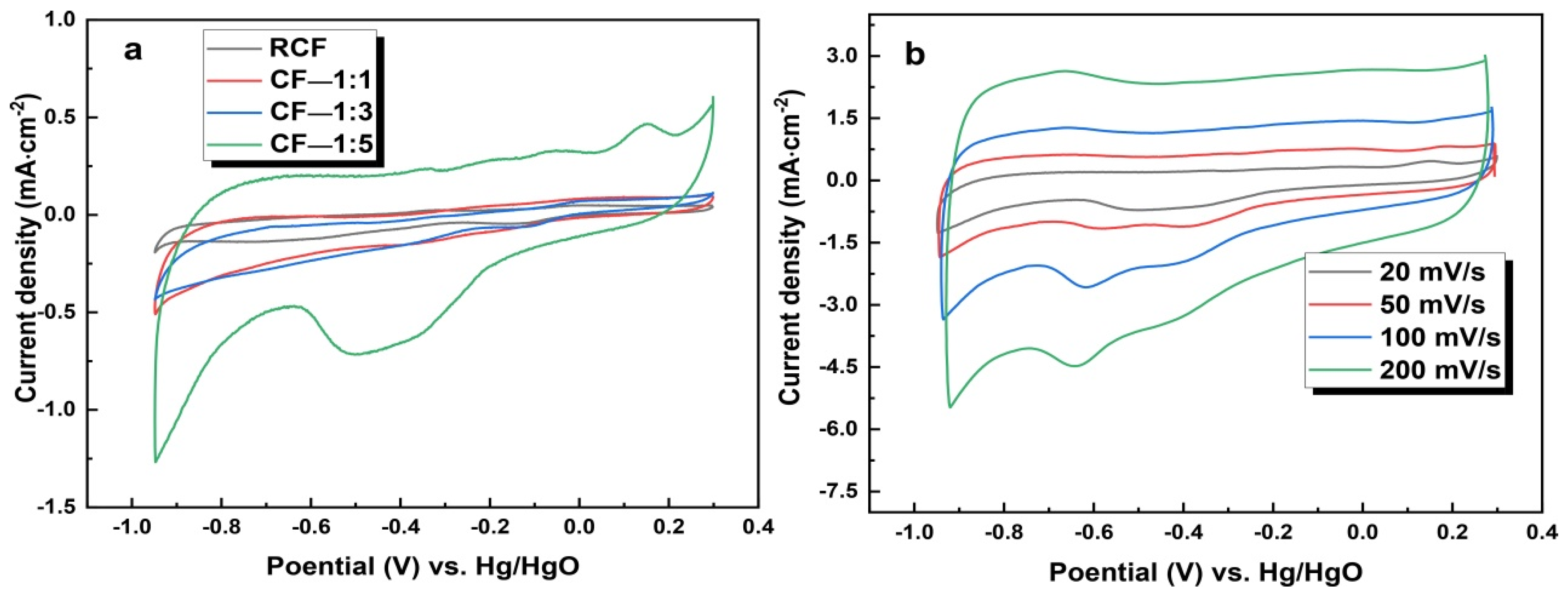
3.4.1. Characteristics of the Cf and Modified Carbon Felt

The morphologies of carbon felt and modified carbon felt were obtained by SEM analysis. Figure 6a,b shows that the fibers on the surface of the original carbon felt (RCF) are smooth, and the surface of the pretreated carbon felt has no adhesion and impurities. As shown in Figure 6c,d, there are many particles on the surface of the carbon felt modified by carbon black and PTFE. The interconnection of these particles dramatically changes the surface structure of the carbon felt electrode, increasing the surface area of the electrode and the gas—liquid contact interface of the carbon felt electrode [2]. The modified carbon felt may enhance the generation of H2O2 when used as a cathode. As shown in Figure 6c,d, after modification, the contact angle increased from 109.64° to 122.33°, and the cathode overflow reduced [2].
Figure 6g,h shows the N2 adsorption/desorption isotherm and pore size distribution of the original carbon felt and the modified carbon felt, respectively. Compared with the original carbon felt, the modified carbon felt shows a larger specific surface area. The specific surface areas of the modified carbon felt CF—1:1, CF—1:3, and CF—1:5 are 2.3978 m2/g, 3.7009 m2/g, and 6.9583 m2/g, respectively. As shown in Figure 6g,h, the total pore volume is 0.015595 cm3/g, 0.066591 cm3/g, and 0.135 cm3/g, respectively. According to the pore size distribution, the modified carbon felt has a smaller pore size, and the nanopore structure on the electrode surface is increased.

3.4.2. Performance of the Modified CF Electrode

The cyclic voltammetry (CV) curves of the original carbon felt and modified carbon felt is shown in Figure 7. After the CV test, it can be seen that an oxygen reduction peak appears at −0.5 V, indicating an oxygen reduction reaction in Figure 7a. Compared with the original carbon felt, the modified carbon felt has a greater peak current density. With the increase of the scanning speed, the oxidation peak moves in the direction of positive voltage, and the reduction peak moves in the direction of negative voltage (Figure 7b). The oxygen reduction peak current of the modified carbon felt electrode was significantly improved, meaning the improved electrochemical performance.

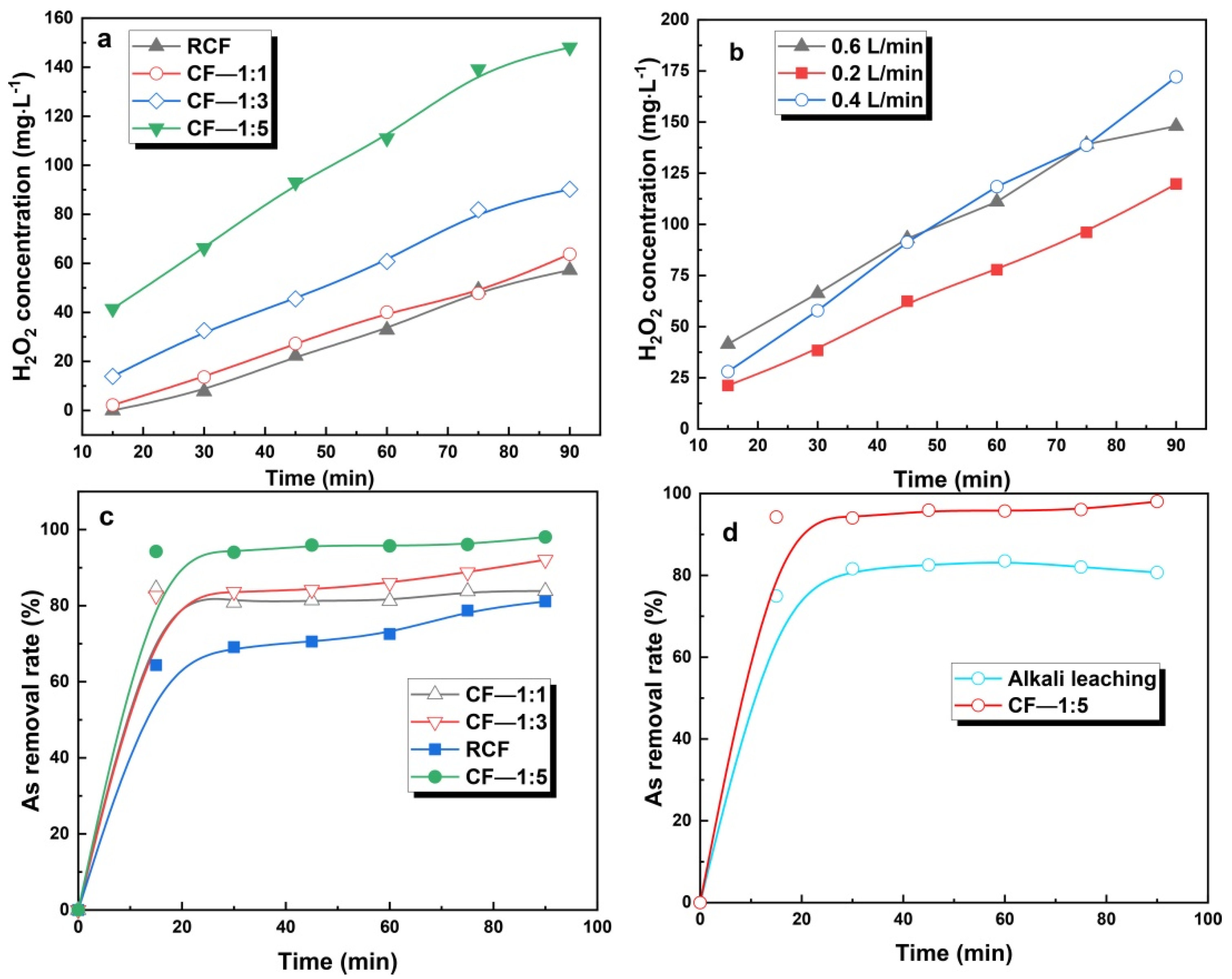
3.4.3. Influencing Factors of Hydrogen Peroxide Generation

The carbon felt cathode was modified by adjusting CB:PTFE ratio. The influence of the electrodes on the generation of H2O2 was carried out through different modified electrodes. As the addition amount continued to increase, the oxygen reduction current and the current density both gradually increased, resulting in the increase in generated H2O2 content. The content of H2O2 generated at CB:PTFE of 1:5 reached 148.048 mg/L. As shown in Figure 8a, the amount of H2O2 produced by CF—1:5 is almost 2.6 times that of unmodified carbon felt.
The increasing trend of H2O2 production was carried out by adjusting the oxygen flow rate, and the results were given in Figure 8b. As the oxygen flow rate increases from 0.2 L/min to 0.6 L/min, the generated H2O2 also increases, and 0.4 L/min was selected as the optimized oxygen flow rate.

3.4.4. Performance of the Modified Electrode in Detoxification of ARCD

A two—electrode system is adopted in the detoxification experiments; a carbon felt electrode, a modified electrode (working electrode), and a graphite rod electrode (counter electrode). The electrochemical oxidation experiment was carried out at the voltage of 1 V. The experimental conditions were as follows: 150 mL of 75 g/L NaOH, solid to liquid ratio of 500 mg/L, experiment temperature of 25 °C, experiment time of 90 min, and the oxygen flow rate of 0.4 L/min. After 90 min of the electrolysis experiment, the removal rate of arsenic reached 98.04%. By comparing pretreated carbon felt and modified carbon felt, the removal rate of arsenic increased from 84.5% to 98.04% at CF of 1:5 (shown in Figure 8c).

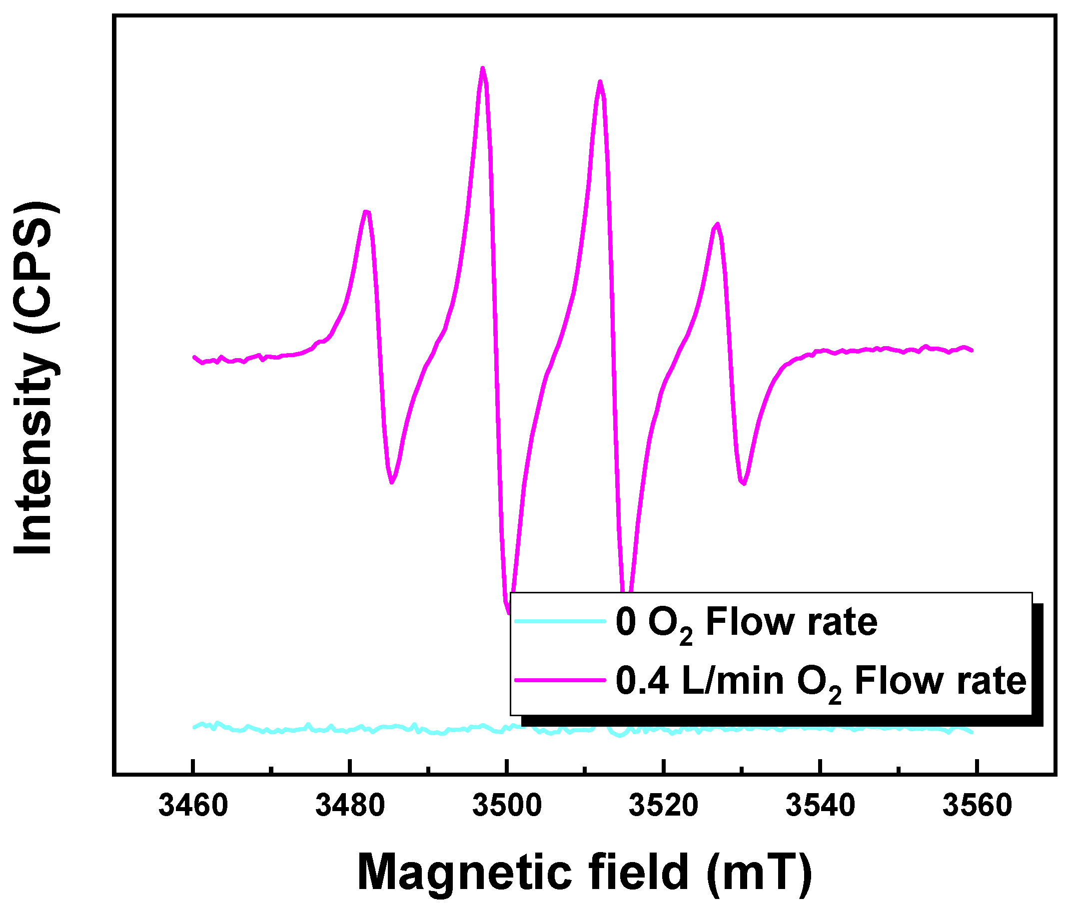
3.5. Electrochemical Oxidation Leaching Mechanisms

The ESR tests were applied in the electrochemical oxidation leaching process to detect the reactive oxygen species, and DMPO was used as a trapping reagent. As shown in Figure 9, when 0.02 mol/L DMPO was added to the electrolyte, significant active ·OH signals were detected under the condition of the oxygen flow rate of 0.4 L/min. Due to the presence of OH, the leaching rate of arsenic can be further improved with respect to alkaline leaching. Furthermore, the arsenic leaching process can be considered as an advanced oxidation process (AOPs). When oxygen is not supplied, the generation of ·OH cannot be detected, further showing that only the transition metals can catalyze the conversion of HO2 into ·OH.
Figure 10 shows the schematic diagram of the experimental setup and arsenic oxidation by reactive oxygen species. A large amount of HO2 with oxidizing properties was in situ generated in the alkaline solution system through the oxidation reaction (5) at the cathode [35,36,37]. In addition, Cu(I) was oxidized by HO2 to Cu(II), triggering the production of ·OH, followed by Cu(II) conversion into copper hydroxide by OH into the final residue, also detected by XRD (Figure 5), and no Cu(I) was detected in the final residue. Therefore, the electrochemical AOPs can be considered an iron-free Fenton-like reaction and can be described by reaction (6) [38,39]. The OH species have very high activity and can oxidize As(III) through reaction (7). The arsenic in the ACRD is oxidized into the liquid phase, and the removal rate of arsenic is further improved compared with alkaline leaching;
O 2 + H 2 O + 2 e HO 2 + OH
Cu + + HO 2 Cu 2 + + OH
AsO 3 3 + OH AsO 4 3 + H 2 O

3.6. The Difference between Alkaline Leaching Process and Electrochemical Advanced Oxidation Leaching Process

The purpose of alkaline leaching of arsenic-containing waste is to transfer arsenic from solid waste to the leachate. However, the alkaline leaching process has disadvantages such as a large amount of waste liquid, easy generation of H2S gas, and low arsenic leaching efficiency. The oxidation treatment of the waste residue containing low valent arsenic is beneficial to transforming the arsenic from a stable form to an unstable form (e.g., a water-soluble state, an exchange state, and a carbonate bond state), thereby increasing the leaching rate of arsenic. The electrochemical advanced oxidation method uses reactive oxygen groups with strong oxidation properties generated in situ to oxidize low arsenic in the ARCD to the leaching solution, which improves the removal rate of arsenic. The alkaline leaching process has the problem of incomplete removal of arsenic. The use of an electrochemical advanced oxidation process can increase the removal rate of arsenic without secondary pollution. The alkaline leaching process cannot oxidize the As(III). The advanced oxidation technology is used to oxidize the low valence arsenic in the solid waste and transfer it into the leaching solution, increasing the arsenic removal rate. As shown in Figure 8d, the removal rate of arsenic is only 80.69%, but it reaches 98.04% through advanced electrochemical oxidation.

4. Conclusions

The use of an electrochemical advanced oxidation leaching process can effectively remove arsenic from arsenic-containing solid waste. By adding carbon black and PTFE to improve the electrochemical performance of the carbon felt, the specific surface area of the carbon felt, the electrochemical performance, and the content of in suit generated H2O2 are all increased. The arsenic in the ARCD can be transferred to the solution by the electrochemical AOPs; therefore, the high-efficiency detoxification of the ARCD is realized. Under the condition of the voltage of 1.0 V, the electrolysis duration of 90 min, the oxygen flow rate of 0.4 L/min, and the CF of 1:5, the removal rate of arsenic reaches 98.4%. In addition, the electrochemical oxidation leaching method avoids secondary pollution and can be considered a clean and efficient arsenic removal method.

Author Contributions

Data curation, B.L.; writing—original draft preparation, M.L.; writing—review and editing, J.Y.; supervision, D.D. and H.D.; project administration, Y.C.; funding acquisition, G.H. All authors have read and agreed to the published version of the manuscript.

Funding

This work was funded by [the National Natural Science Foundation of China] (Grant No. 52004252), [the National Key Research and Development Program of China] (Grant No. 2018YFC1901601), [the Postdoctoral Research Grant in Henan Province] (Grant No. 201902016), [Henan Province Key R&D and Promotion Special (Scientific and Technical) Project] (Grant No. 212102310600) and [the Key Research Project of Henan Province Colleges and Universities] (Grant No. 20A440011).

Institutional Review Board Statement

Not applicable.

Informed Consent Statement

Not applicable.

Data Availability Statement

Not applicable.

Acknowledgments

This work was financially supported by the National Natural Science Foundation of China (Grant No. 52004252), the National Key Research and Development Program of China (Grant No. 2018YFC1901601), the Postdoctoral Research Grant in Henan Province (Grant No. 201902016), Henan Province Key R&D and Promotion Special (Scientific and Technical) Project (Grant No. 212102310600) and the Key Research Project of Henan Province Colleges and Universities (Grant No. 20A440011).

Conflicts of Interest

The authors declare no conflict of interest.

References

  1. Yang, B.; Zhang, G.L.; Deng, W.; Ma, J. Review of arsenic pollution and treatment progress in nonferrous metallurgy industry. Adv. Mater. Res. 2013, 634–638, 3239–3243. [Google Scholar] [CrossRef]
  2. Yu, F.; Zhou, M.; Yu, X. Cost-effective electro-Fenton using modified graphite felt that dramatically enhanced on H2O2 electro-generation without external aeration. Electrochim. Acta 2015, 163, 182–189. [Google Scholar] [CrossRef]
  3. Liu, D.G.; Min, X.B.; Ke, Y.; Chai, L.Y.; Liang, Y.J.; Li, Y.C.; Yao, L.W.; Wang, Z.B. Co-treatment of flotation waste, neutralization sludge, and arsenic-containing gypsum sludge from copper smelting: Solidification/stabilization of arsenic and heavy metals with minimal cement clinker. Environ. Sci. Pollut. Res. 2018, 25, 7600–7607. [Google Scholar] [CrossRef]
  4. Chung, J.Y.; Yu, S.D.; Hong, Y.S. Environmental source of arsenic exposure. J. Prev. Med. Public Health 2014, 47, 253. [Google Scholar] [CrossRef] [PubMed] [Green Version]
  5. Choong, T.; Chuah, T.G.; Robiah, Y.; Koay, F.; Azni, I. Arsenic toxicity, health hazards and removal techniques from water: An overview. Desalination 2007, 217, 139–166. [Google Scholar] [CrossRef]
  6. Xu, B.; Ma, Y.; Gao, W.; Yang, J.; Jiang, T. A review of the comprehensive recovery of valuable elements from copper smelting open-circuit dust and arsenic treatment. JOM 2020, 72, 3860–3875. [Google Scholar] [CrossRef]
  7. Jaroíková, A.; Ettler, V.; Mihaljevi, M.; Drahota, P.; Culka, A.; Racek, M. Characterization and pH-dependent environmental stability of arsenic trioxide-containing copper smelter flue dust. J. Environ. Manag. 2018, 209, 71–80. [Google Scholar] [CrossRef] [PubMed]
  8. Guo, X.Y.; Yi, Y.; Shi, J.; Tian, Q.H. Leaching behavior of metals from high-arsenic dust by NaOH–Na2S alkaline leaching. Trans. Nonferrous Met. Soc. China 2016, 26, 575–580. [Google Scholar] [CrossRef]
  9. Liu, W.; Han, J.; Ou, Z.; Wu, D.; Qin, W. Arsenic and antimony extraction from high arsenic smelter ash with alkaline pressure oxidative leaching followed by Na2S leaching. Sep. Purif. Technol. 2019, 222, 53–59. [Google Scholar]
  10. Chen, Y.; Liao, T.; Li, G.; Chen, B.; Shi, X. Recovery of bismuth and arsenic from copper smelter flue dusts after copper and zinc extraction. Miner. Eng. 2012, 39, 23–28. [Google Scholar] [CrossRef]
  11. Wang, Y.; Fang, X.; Deng, P.; Rong, Z.; Cao, S. Study on thermodynamic model of arsenic removal from oxidative acid leaching. J. Mater. Res. Technol. 2020, 9, 3208–3218. [Google Scholar] [CrossRef]
  12. Zhong, D.P.; Li, L.; Tan, C. Separation of arsenic from the antimony-bearing dust through selective oxidation using CuO. Metall. Mater. Trans. B 2017, 48, 1308–1314. [Google Scholar] [CrossRef]
  13. Zhong, D.P.; Lei, L.I. Separation of arsenic from arsenic—Antimony-bearing dust through selective oxidation—Sulfidation roasting with CuS. Trans. Nonferrous Met. Soc. China 2020, 30, 223–235. [Google Scholar] [CrossRef]
  14. Shan, C.; Tong, M. Efficient removal of trace arsenite through oxidation and adsorption by magnetic nanoparticles modified with Fe-Mn binary oxide. Water Res. 2013, 47, 3411–3421. [Google Scholar] [CrossRef]
  15. Hu, C.Y.; Lo, S.L.; Kuan, W.H. High concentration of arsenate removal by electrocoagulation with calcium. Sep. Purif. Technol. 2014, 126, 7–14. [Google Scholar] [CrossRef]
  16. Jin, Y.; Fei, L.; Tong, M.; Hou, Y. Removal of arsenate by cetyltrimethylammonium bromide modified magnetic nanoparticles. J. Hazard. Mater. 2012, 227–228, 461–468. [Google Scholar] [CrossRef]
  17. Bui, T.H.; Kim, C.; Hong, S.P.; Yoon, J. Effective adsorbent for arsenic removal: Core/shell structural nano zero-valent iron/manganese oxide. Environ. Sci. Pollut. Res. 2017, 24, 24235–24242. [Google Scholar] [CrossRef] [PubMed]
  18. Li, W.; Han, J.; Liu, W.; Qin, W.; Cai, L. Arsenic removal from lead-zinc smelter ash by NaOH-H2O2 leaching. Sep. Purif. Technol. 2019, 209, 128–135. [Google Scholar] [CrossRef]
  19. Zhao, Y.; Qiu, W. Arsenic oxidation and removal from flue gas using H2O2/Na2S2O8 solution. Fuel Process. Technol. 2017, 167, 355–362. [Google Scholar] [CrossRef]
  20. Tubić, A.; Agbaba, J.; Dalmacija, B.; Rončević, S.; Ivančev-Tumbas, I. Effects of O3, O3/H2O2 and coagulation on natural organic matter and arsenic removal from typical northern Serbia source water. Sep. Sci. Technol. 2010, 45, 2453–2464. [Google Scholar] [CrossRef]
  21. Kim, D.H.; Bokare, A.D.; Min, S.K.; Choi, W. Heterogeneous catalytic oxidation of As(III) on nonferrous metal oxides in the presence of H2O2. Environ. Sci. Technol. 2015, 49, 3506. [Google Scholar] [CrossRef]
  22. Oturan, M.A. Electrochemical advanced oxidation technologies for removal of organic pollutants from water. Environ. Sci. Pollut. Res. 2014, 21, 8333–8335. [Google Scholar] [CrossRef] [PubMed] [Green Version]
  23. Luo, Y.; Wu, Y.; Huang, C.; Xiao, D.; Chu, P.K. Graphite felt incorporated with MoS2/rGO for electrochemical detoxification of high-arsenic fly ash. Chem. Eng. J. 2019, 382, 122763. [Google Scholar] [CrossRef]
  24. Zheng, S.; Zhang, Y.; Wei, J. Reinforced As(III) oxidation by the in-situ electro-generated hydrogen peroxide on MoS2 ultrathin nanosheets modified carbon felt in alkaline media. Electrochim. Acta 2017, 252, 245–253. [Google Scholar]
  25. Wang, X.Q.; Liu, C.P.; Yuan, Y.; Li, F.B. Arsenite oxidation and removal driven by a bio-electro-Fenton process under neutral pH conditions. J. Hazard. Mater. 2014, 275, 200–209. [Google Scholar] [CrossRef]
  26. Xia, G.; Lu, Y.; Xu, H. Electrogeneration of hydrogen peroxide for electro-Fenton via oxygen reduction using polyacrylonitrile-based carbon fiber brush cathode. Electrochim. Acta 2015, 158, 390–396. [Google Scholar] [CrossRef]
  27. Sopaj, F.; Rodrigo, M.A.; Oturan, N.; Podvori Ca, F.I.; Pinson, J.; Oturan, M.A. Influence of the anode materials on the electrochemical oxidation efficiency. Application to oxidative degradation of the pharmaceutical amoxicillin. Chem. Eng. J. 2015, 262, 286–294. [Google Scholar] [CrossRef]
  28. Tian, J.; Olajuyin, A.M.; Mu, T.; Yang, M.; Xing, J. Efficient degradation of rhodamine B using modified graphite felt gas diffusion electrode by electro-Fenton process. Environ. Sci. Pollut. Res. 2016, 23, 11574–11583. [Google Scholar] [CrossRef]
  29. Chen, S.; Tang, L.; Feng, H.; Zhou, Y.; Zeng, G.; Lu, Y.; Yu, J.; Ren, X.; Peng, B.; Liu, X. Carbon felt cathodes for electro-Fenton process to remove tetracycline via synergistic adsorption and degradation. Sci. Total. Environ. 2019, 670, 921–931. [Google Scholar] [CrossRef]
  30. Liu, X.; Yang, D.; Zhou, Y.; Zhang, J.; Lin, T. Electrocatalytic properties of N-doped graphite felt in electro-Fenton process and degradation mechanism of levofloxacin. Chemosphere 2017, 182, 306–315. [Google Scholar] [CrossRef]
  31. Li, K.; Liu, J.; Li, J.; Wan, Z. Effects of N mono- and N/P dual-doping on H2O2, OH generation, and MB electrochemical degradation efficiency of activated carbon fiber electrodes. Chemosphere 2018, 193, 800–810. [Google Scholar] [CrossRef] [PubMed]
  32. Ganiyu, S.O.; Le, T.H.; Bechelany, M.; Esposito, G.; Hullebusch, E.V.; Oturan, M.A.; Cretin, M. A hierarchical cofe-layered double hydroxide modified carbon-felt cathode for heterogeneous electro-Fenton process. J. Mater. Chem. A 2017, 5, 3655–3666. [Google Scholar] [CrossRef]
  33. Camacho, J.; Wee, H.Y.; Kramer, T.A.; Autenrieth, R. Arsenic stabilization on water treatment residuals by calcium addition. J. Hazard. Mater. 2009, 165, 599–603. [Google Scholar] [CrossRef] [PubMed]
  34. Bindi, L.; Catelani, T.; Chelazzi, L.; Bonazzi, P. Reinvestigation of the crystal structure of lautite, CuAsS. Acta Crystallogr. Sect. E Struct. Rep. Online 2008, 64, i22. [Google Scholar] [CrossRef] [Green Version]
  35. Zhang, X.; Tian, J.; Han, H.; Sun, W.; Hu, Y.; Wang, T.; Yang, Y.; Cao, X.; Tang, H. Arsenic removal from arsenic-containing copper and cobalt slag using alkaline leaching technology and MgNH4AsO4 precipitation. Sep. Purif. Technol. 2020, 238, 116422. [Google Scholar] [CrossRef]
  36. Zhan, M.; Xi, Y.; Xian, Q.; Kong, L. Photosensitized degradation of bisphenol a involving reactive oxygen species in the presence of humic substances. Chemosphere 2006, 63, 378–386. [Google Scholar] [CrossRef]
  37. Burns, J.M.; Cooper, W.J.; Ferry, J.L.; King, D.W.; Dimento, B.P.; Mcneill, K.; Miller, C.J.; Miller, W.L.; Peake, B.M.; Rusak, S.A. Methods for reactive oxygen species (ROS) detection in aqueous environments. Aquat. Sci. 2012, 74, 683–734. [Google Scholar] [CrossRef]
  38. Liu, B.; Wang, X.; Yu, X.; Zheng, S.; Du, H.; Dreisinger, D.; Yi, Z. A promising approach to recover a spent scr catalyst: Deactivation by arsenic and alkaline metals and catalyst regeneration. Chem. Eng. J. 2018, 342, 1–8. [Google Scholar] [CrossRef]
  39. Bokare, A.D.; Choi, W. Review of iron-free Fenton-like systems for activating H2O2 in advanced oxidation processes. J. Hazard. Mater. 2014, 275, 121–135. [Google Scholar] [CrossRef]
Figure 1. (a) XRD pattern of ARCD, (b) XPS spectra of ARCD, full spectrum, (c) As 3d, (d) Cu 2p3/2, (e) SEM-EDS of ARCD.
Minerals 11 01311 g001aMinerals 11 01311 g001b
Figure 2. The plots of ΔrG°~T for the Equations (2)–(4) (Drawn by HSC 5.0 chemistry software, Outokumpu Research, Finland).
Minerals 11 01311 g002
Figure 3. (a) Eh—pH diagrams of As, (b) Pb, (c) Zn, and (d) Cu, respectively.
Minerals 11 01311 g003
Figure 4. (a) Effect of NaOH concentration on the leaching efficiencies (70 °C, 10:1 mL/g and 90 min), (b) experimental reaction duration (70 °C, 10:1 mL/g and 75 g/L) and (c) reaction temperature (75 g/L, 10:1 mL/g and 90 min).
Minerals 11 01311 g004
Figure 5. (a,b) XRD pattern, (c) XPS spectra, full spectrum, (d) As 3d of the alkaline leaching residue.
Minerals 11 01311 g005
Figure 6. Morphological changes of modified CF are as follows: (a) low magnification and (b) high magnification SEM images of RCF, (c) low-power and (d) high—power SEM images of modified CF, (e) Contact angle of the original CF electrode, (f) Contact angle of the modified CF electrode, (g) pore size distribution, and (h) N2 adsorption/desorption isotherms.
Minerals 11 01311 g006aMinerals 11 01311 g006b
Figure 7. (a) CV diagram of RCF and modified CF, (b) changes of CF—1:5 electrode with scavenging speed electrode CV.
Minerals 11 01311 g007
Figure 8. (a) Content of H2O2 in situ generated by different electrodes, (b) the change of H2O2 generated by CF—1:5 with different oxygen flow rate, (c) the change of arsenic removal rate from the ACRD by different electrodes, (d) and the difference between alkaline leaching and electrochemical advanced oxidation leaching.
Minerals 11 01311 g008
Figure 9. ESR tests of ·OH during the electrochemical oxidation leaching process.
Minerals 11 01311 g009
Figure 10. (a) Schematic diagram of the experimental setup and (b) Schematic diagram of the oxidation process of low arsenic by reactive oxygen species.
Minerals 11 01311 g010
Table 1. The main compositions of the ARCD (* Data from XRF and other data from ICP, wt.%).
ElementAs2O3CuOZnOPbOBi2O3Fe2O3* SO3Others
Content8.7815.311.9517.76.621.6320.7327.38
Publisher’s Note: MDPI stays neutral with regard to jurisdictional claims in published maps and institutional affiliations.

