Abstract
This paper provides a technical approach for efficiently recovering Mg from ferronickel slag to produce high-quality magnesium oxide (MgO) by using the sulfuric acid leaching method under atmospheric pressure. The leaching rate of magnesium is 84.97% after a typical one-step acid leaching process, which is because Mg in FNS mainly exists in the forsterite (Mg2SiO4) phase, which is chemically stable. In order to increase the leaching rate, a two-step acid leaching process was proposed in this work, and the overall leaching rate reached up to 95.82% under optimized conditions. The response surface methodology analysis for parameter optimization and Mg leaching rules revealed that temperature was the most critical factor affecting the Mg leaching rate when the sulfuric acid concentration was higher than 2 mol/L, followed by acid leaching time. Furthermore, interactive behavior also existed between the leaching temperature and leaching time. The leaching kinetics of magnesium from FNS followed a shrinkage-nuclear-reaction model with composite control, which were chemically controlled at lower temperatures and diffusion controlled at higher temperatures; the corresponding apparent activation energy was 19.57 kJ/mol. The leachate can be used to obtain spherical-like alkali magnesium carbonate particles with diameters of 5–10 μm at 97.62% purity. By using a further calcination process, the basic magnesium carbonate can be converted into a light magnesium oxide powder with a particle size of 2–5 μm (MgO content 94.85%), which can fulfill first-level quality standards for industrial magnesium oxide in China.
1. Introduction
Ferronickel slag (FNS) is considered as the main solid wastes discharged from high-temperature smelting of laterite ores during the ferronickel production process. An approximate estimation shows that 12–14 tons of FNS can be generated within the production process of 1 ton of nickel alloy [1,2]. The output of ferronickel slag has increased to approximately 40 Mt in 2020, ranking as the fourth largest industrial solid waste in China, followed by iron slag, steel slag, and red mud [3]. However, at the present stage, less than 10% of FNS has been utilized [4], and most FNS was disposed of in an open environment, which not only poses a great potential threat to the environment and human health due to its hazardous components (e.g., chromium) but also results in a large waste of its contending resources. Thus, clean and highly efficient utilization of FNS represents a meaningful and interesting research area, especially given the global awareness of carbon reduction.
Over the past few decades, efforts have been made in the utilization of ferronickel slag. Most have focused on applying ferronickel slag for making construction and building materials (e.g., cement, concrete, and geopolymers) because of the high contents of amorphous SiO2 [5,6,7,8,9], producing glass ceramics [10,11] and mineral wool [12] due to the glass and microcrystalline structure, and preparing forsterite refractory materials based on its higher MgO content [13,14,15,16]. However, these application pathways have some shortcomings, such as complex processes, large initial investment, and low product quality, resulting in low efficiency of FNS utilization. FNS contains appreciable amounts of base metals and is also considered to be an important secondary source of valuable metals. Most relevant studies have focused on the extraction of iron, nickel, cobalt, and chromium in the past [17,18,19]. The main methods include high-temperature roasting [20], atmospheric or oxygen pressure leaching with acid [21,22,23,24], and microbial leaching [25,26].
In the last decade, with the gradual exhaustion of natural magnesium-rich mineral resources, efficient utilization of magnesium in FNS has received more attention. Many methods for recovering magnesium from ferronickel slag have been reported, e.g., vacuum reduction [27], ammonium sulfate roasting [28], sodium hydroxide(NaOH) [29], hydrochloric acid (HCl) [30], and sulfuric acid (H2SO4) [31] leaching. Although vacuum reduction has a higher leaching rate (97.74%), operation at elevated temperatures (1573 K) is not attractive for processing secondary resources. Compared with the vacuum reduction method, the ammonium sulfate roasting method is more competitive due to its lower roasting temperature of 300~600 °C, and without consuming acid and alkali. However, only 90% of magnesium could leach from FNS into water under the optimum conditions [28]. The leaching rate of magnesium from FNS was 73.10% with sodium hydroxide, which was not satisfactory [29]. Due to its simple process, low investment cost, and relatively low environmental pollution, the atmospheric pressure acid leaching process is a potential direction for industrial applications. Since silicate minerals are relatively difficult to dissolve in HCl in comparison to oxides and hydroxides [30], sulfuric acid is the preferred choice. According to Gao’s study [31], 87.46% of Mg was removed into the leach liquor through a two-stage sulfuric acid leaching process. Gao’s leaching results are not ideal and the operation conditions are relatively tough. FNS sulfuric acid leachate is the mother liquor of magnesium products, which is similar to industrial magnesium sulfate solution. However, studies have already proved that iron, aluminum, and other metals will be synchronously leached during the sulfuric acid leaching of FNS [32], so the leachate contains not only a large amount of Mg2+, but also other metal ions, such as Fe2+, Al3+, Cr2+, etc. The negative effects of foreign metal ions on the magnesium product are inevitable. Producing high-purity magnesium products is a challenging task, which greatly depends on the purifying efficiency of Mg2+ in the leaching solution. Thus far, it is still urgent to efficiently recover magnesium from FNS to yield high purity magnesium products under mild technology conditions.
In this study, the leaching behavior of magnesium from FNS in sulfuric acid solution, purification of Mg2+, and preparation of high purity magnesium oxide are discussed. The appropriate factors for sulfuric acid leaching were determined by single-factor experiments. The response surface analysis was used to optimize the leaching process parameters and clarify the extent of each parameter influencing the leaching operation. The dissolution kinetics of magnesium from FNS were also investigated to provide theoretical guidance to elucidate the leaching process. This study proposed a feasible method for efficiently recovering Mg from ferronickel slag to prepare light magnesium oxide.
2. Materials and Methods
2.1. Materials
The FNS used in this study was obtained from a ferronickel smelting plant that operates with the rotary kiln-electric furnace (RKEF) process in Hebei Province, China. The main chemical composition of the FNS is shown in Table 1. It is characterized by a high Mg and Fe content and low Al and Ca content.

Table 1.
Chemical composition of ferronickel slag (wt/%).
X-ray powder diffraction (XRD) in combination with the Rietveld method was used to determine the phases in the FNS. The BGMN program was applied for Rietveld refinement [33]. Figure 1 shows the mineralogical compositions of the sample determined by Rietveld refinement. The Rwp value was 7.88%. Forsterite is the main component with a small amount of calcite and quartz with values of 1.41% and 0.08%. In addition, the low background of the XRD pattern indicates that the ferronickel slag mineral has a large crystallinity, which makes the process of ore dissolution more difficult.
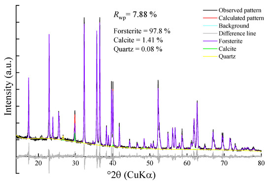
Figure 1.
XRD pattern of ferronickel slag.
2.2. Methods
2.2.1. Sulfuric Acid Leaching
Ferronickel slag was first broken into fine particles with a size less than 2 mm by double teeth roll crusher then the uniformly mixed fine particles were ground through a sampling machine, and the collected powder was used as the raw sample used for the primary leaching experiment. In the leaching experiments, a specific concentration of sulfuric acid solution was poured into a conical flask, which was placed in a constant temperature water bath and heated to a specified temperature. Then, 20 g of FNS samples was soaked in sulfuric acid with a specific liquid-solid ratio (L/S) and magnetically stirred at a specified speed for a time while keeping the flask sealed. After the reaction was completed, the obtained mixture was carefully filtered with a vacuum filter, and the leaching residue was washed twice with hot sulfuric acid solution and thoroughly washed with deionized water until no SO42− was detected in the filtrate (tested by BaCl2). The filtrate was collected for the subsequent experiment, while the residue was dried at 100 °C for 2 h, and the mass of the dried residue was measured. According to the China industry standard-named determination of 22 metal elements in solid waste (HJ 781-2016), the dried residue was completely digested on the electric heating plate in the mixed acid solution, and the Mg content was measured by atomic absorption spectrophotometry to determine the leaching percentage, which was calculated using the following equations:
where , , and are the Mg of primary, secondary, and comprehensive leaching percentage (%), respectively, , , and are the mass (g) of the first-stage leaching residue, second-stage leaching residue, and raw FNS, respectively, and , , and are the mass percent (%) of Mg in them, respectively.
The leaching residues with the highest Mg leaching ratio in primary and secondary leaching were analyzed by XRF and XRD, and the results were compared with the initial slag sample.
2.2.2. Purification of Magnesium
During the separation of Mg from impurities, 100 mL of acid leaching solution was first mixed with 1.5 mL of 15% H2O2 in a 250 mL beaker, then the breaker was heated at 30 °C and simultaneously stirred at a speed of 200 rpm for 10 min to convert Fe2+ into Fe3+. A sensitivity test was performed to assess whether Fe2+ was completely oxidized by using 0.1 mol/L potassium ferricyanide. Then, the pH value of the solution was adjusted to pH 7 using about 3 mL aqueous ammonia, so that the impurity ions such as Fe3+, Al3+, and Cr3+ in the leachate could be converted into hydroxide precipitation. Next, the pH of the solution was adjusted sequentially with aqueous ammonia in order to further remove the hybrids and obtain a purer magnesium sulfate solution and precipitate.
At the end of the purification process, the magnesium sulfate solution and precipitate were thoroughly separated by vacuum filtration. To evaluate the purifying efficiency, the magnesium filtrate was precipitated as hydroxide magnesium (Mg(OH)2) by sodium hydroxide; the higher the Mg(OH)2 content, the higher the impurity removal rate and the better the impurity removal effect. At the same time, the Mg content of filter residue was analyzed by XRF to calculate the loss ratio of magnesium according to Equation (4):
where is the loss ratio of magnesium, is the mass (g) of filter residue after impurity removal, is the Mg content (%) in it, and and are the solution volume (L) and its Mg content (g/L) before impurity removal, respectively.
2.2.3. Preparation of Magnesium Oxide
In this study, the alkaline magnesium carbonate calcination process was used to produce highly pure magnesium oxide. Firstly, the magnesium was precipitated into basic magnesium carbonate: 100 mL of purified magnesium sulfate solution was transferred into a 250 mL beaker, and a specified amount of ammonia water and ammonium bicarbonate were added. After stirring at a constant temperature for a certain period of time, a basic magnesium carbonate precipitation was obtained (the main reactions during the process are shown in Equation (5) [34]). After vacuum filtration, cleaning, and drying, basic magnesium carbonate powder was obtained. The magnesium precipitation effect is evaluated by the purity of 4MgCO3•Mg(OH)2•4H2O (Equation (6)) and the metal conversion rate (Equation (7)):
where is the purity of 4MgCO3•Mg(OH)2•4H2O, is the content of Mg found in the obtained 4MgCO3•Mg(OH)2•4H2O, is the theoretical amount of Mg in 4MgCO3•Mg(OH)2•4H2O, is the conversion percentage of metals, and and are the total amount of metals after precipitation and in the original solution, respectively.
5MgSO4 + 6NH3·H2O + 4NH4HCO3→4MgCO3•Mg(OH)2•4H2O + 5(NH4)2SO4
Secondly, the obtained basic magnesium carbonate was placed in a muffle furnace at a rate of 10 °C/min and heated to 900 °C and then calcined at a constant temperature for 90 min (the main chemical reaction of calcination is shown in Equation (8)). Then, the furnace was cooled to room temperature, and the obtained powder was light magnesium oxide. Figure 2 shows the process flow diagram of recovering Mg from FNS to prepare MgO.
4MgCO3•Mg(OH)2•4H2O→5MgO + 4CO2↑ + 6H2O
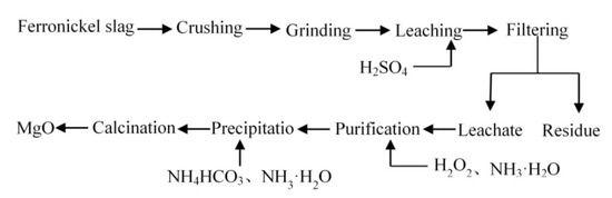
Figure 2.
Process flow of recovering Mg from FNS to prepare MgO.
2.3. Characterization Methods
The Mg content in all leaching residues was determined by atomic absorption spectrophotometry (Z-2000, Tokyo, Japan) under the following instrument operating conditions: acetylene flow of 3.0 L/min, lamp current of 4 mA, slit width of 1.0 nm. The chemical compositions of ferronickel slag and leaching residues were examined using an X-ray fluorescence spectrometer (Kyoto, Japan, XRF-1800), which operated at 60 kV voltage and 140 mA current with a scanning speed of 300°/min. The phase composition of the samples was determined by the Rietveld method using X-ray diffraction (XRD) data. The measurements were performed on a Rigaku Ultima IV instrument (Kyoto, Japan, at 40 mA and 40 kV) using CuKα radiation with a wavelength of 1.5406 Å in 10° to 80° 2θ range with an angular speed of 20°/min. The BGMN program was applied for Rietveld refinement. The morphology of the samples was characterized by a scanning electron microscope (SEM, MV-RR-CNJ-0010, Shanghai, China) equipped with an energy dispersive spectroscopy (EDS) detector. All chemicals used in the study were from the laboratory of the University of Science and Technology, Beijing, and were analytical grade. Deionized water was used throughout the experiments and analytical measurements.
3. Results and Discussion
3.1. The Acid Leaching Process of Ferronickel Slag
The effects of FNS grinding fineness, acid concentration, liquid-to-solid ratio, leaching temperature, leaching time, and stirring speed on the magnesium leaching percentage were studied, and the results are shown in Figure 3.
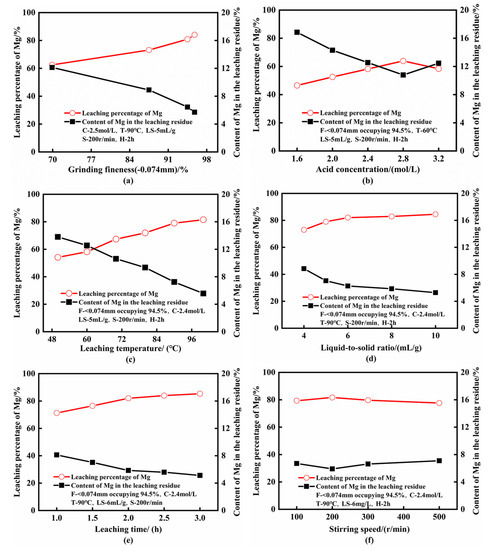
Figure 3.
Effect of variables on the efficiency of leaching magnesium from ferronickel slag (a) grinding fineness; (b) acid concentration; (c) leaching temperature; (d) liquid-to-solid ration; (e) leaching time; (f) stirring speed (F—grinding fineness; C—acid concentration; T—leaching temperature; LS—liquid-to-solid ratio; H—leaching time; S—stirring speed).
Figure 3a indicates that the leaching efficiency of magnesium increased gradually with decreasing particle size. This is attributed to the increase in the specific surface areas of the samples, which provides a greater reaction interface between the sulfuric acid and FNS particles. However, a smaller particle size does not necessarily lead to a higher extraction rate and may even have a negative influence [35]. Therefore, the optimum grinding fineness was determined to be −0.074, mm accounting for 94.5%.
Figure 3b shows that a modest increase in acid concentration was beneficial to increase the Mg leaching rate. Around 63.90% of magnesium can be extracted when the concentration of acid reaches 2.8 mol/L, and the reasons for the decrease at a higher concentration were because (1) the viscosity of the slurry increased, (2) the mass transfer efficiency was reduced, and (3) the soluble sulfuric magnesium was captured in the residue. A previous study also concluded that an appropriate sulfuric acid concentration was identified to ensure a reasonable final pH level to inhibit the generation of colloidal silica and produce acceptable solid-liquid separation characteristics of the leaching slurry [18]. Hence, a lower sulfuric acid concentration is practically acceptable.
The results of Figure 3c show that the extraction rate of magnesium increased by 27.39% when the temperature increased from 50 °C to 100 °C. Correspondingly, the content of Mg in the leaching residue decreased from 12.55% to 5.56%, which indicates that the leaching rate of magnesium is highly dependent on temperature. An increase in temperature will increase the available energy in the reaction system and accelerate the thermal movement of H+ and crystal lattice molecules of forsterite. With a faster diffusion rate, the effective number of collisions between H+ and FNS particles increases, which makes it easier for H+ ions to abolish the crystal lattice of forsterite, and thus, enhances the Mg2+ leaching rate. A higher leaching temperature is advantageous for the increase in Mg leaching velocity and leaching ratio. However, H2SiO3 may be formed when leaching at a temperature above 99 °C, which is harmful to the leaching of Mg, because H2SiO3 can increase the solution viscosity by forming a colloidal substance. SiO2 may be the stable form of Si when the leaching occurs at a temperature lower than 99 °C, which is less harmful [31]. Therefore, the sulfuric acid leaching temperature of FNS should be controlled lower than 99 °C.
Figure 3d illustrates that increasing the liquid-to-solid ratio is beneficial to the extraction of magnesium. As the liquid-to-solid ratio increases, the slurry density gradually decreases, accelerating mass transfer, and therefore, providing benefits to mineral dissolution. Moreover, as the solution viscosity decreases, FNS particles can more efficiently contact sulfuric acid. However, it was noteworthy that a relatively low degree of extraction improvement occurred when the liquid-to-solid ratio exceeded 6 mL/g.
Figure 3e shows the tendency of magnesium extraction when the leaching time gradually increases from 60 min to 180 min. Moreover, it was observed that magnesium extractions increased significantly with the increase in leaching time until 120 min, and then gradually reached a stable state. This can be attributed to the fact that only a small amount of unreacted FNS particles remained after leaching for 120 min, and the probability of intermolecular collisions decreased with the consumption of sulfuric acid. In addition, amorphous silica was produced simultaneously, which was easy to accumulate on the surface of the reactor and hinder the reaction.
As shown in Figure 3f, the stirring speed has an indistinctive effect on the leaching rate. The stirring should ensure that the particles are effectively suspended, but cannot be too fast; this is because excessive mixing speed causes the material in the leaching system to rotate, which makes it easy to agglomerate on the stirring bar, resulting in a poor mass transfer effect and slow leaching rate.
Considering the leaching efficiency, filterability of leaching slurry, and energy consumption, the proper technical conditions for primary leaching were determined as follows: raw material grinding fineness of −0.074 mm occupied 94.5%, acid concentration of 2.4 mol/L, leaching temperature of 90 °C, liquid-to-solid ratio of 6 mL/g, leaching time of 120 min, stirring speed of 200 r/min, and leaching percentage of Mg was 82.05%.
The second leaching of the primary residue was operated for more Mg recovery. The influence of the main factors on the corresponding Mg extractions and Mg contents are presented in Figure 4.
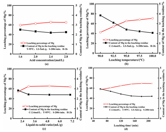
Figure 4.
Influence of the main factors on the leaching rate of Mg in secondary acid leaching (a) acid concentration; (b) leaching temperature; (c) liquid-to-solid ration; (d) leaching time.
It is not difficult to find that the influence of the main factors on the magnesium leaching rate was similar in the two leaching steps. The optimum sulfuric acid concentration for the second leaching step was also 2.4 mol/L. The influence of temperature on the secondary leaching process was stronger, and the leaching rate increased by 23.03% when the temperature was raised from 90 °C to 95 °C. The optimum liquid-solid ratio of the secondary process was 3 mL/g, which was lower than that of the primary acid leaching process, which occurred because there are fewer substances that can react with sulfuric acid in the primary acid leaching residue than the original ferronickel slag. The improvement in the second-stage acid leaching process by prolonging the leaching time was more obvious than in the first-stage acid leaching process. The leaching rate of the second-stage acid leaching process increased by 3.37% as the leaching time increased from 120 min to 150 min. Overall, the optimum factors for second leaching were: acid concentration of 2.4 mol/L, leaching temperature of 95 °C, liquid-to-solid ratio of 3 mL/g, leaching time of 150 min, stirring speed of 200 r/min, and secondary Mg leaching percentage of 68.21%, then the comprehensive leaching percentage of FNS was 94.29%.
3.2. Analysis of the Leaching Residues
The XRF analysis results of leaching residues obtained under the optimized conditions are presented in Table 2. The main component in the residues changed to SiO2 after acid leaching, and the contents of other impurities were substantially low. The X-ray diffraction pattern of the residues (Figure 5) demonstrates that after the primary acid leaching process, the intensity of the diffraction peak of magnesium olivine evidently decreases, which indicates that most crystalline and glassy phases in the ferronickel slag have been leached out by acid. After the secondary acid leaching process, there was only a trace of quartz remaining, and the peak of magnesia olivine disappeared, which indicated that the minerals containing magnesium and iron in FNS basically reacted completely. The main component of the secondary acid leaching residue is purer amorphous silica, which seems to be more environmentally friendly and suitable for further disposal.
Table 2.
XRF comparative analysis of the two stages acid leaching residue.
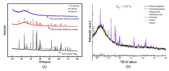
Figure 5.
(a) XRD comparison of the FNS and acid leaching residues; (b) Rietveld XRD diagram of the primary leaching residue.
3.3. Response Surface Optimization
In order to optimize the process conditions and explore the main process factors and their interactions, response surface optimization was performed. In this study, the optimization of significant factors was performed via the response surface methodology (RSM). Table 3 summarizes the range of independent variables and their levels. Experiments were carried out according to the Box-Behnken design (BBD), as shown in Table 4.
Table 3.
Experimental variables and levels used in the response surface design.
Table 4.
Experimental scheme and results from the response surface designed experiment.
According to the experimental results in Table 4, the Design Expert software (Stat-Ease, Inc., 1300 Godward Street Northeast; Version 12.0.3) was used to execute the regression analysis, and the response surface equation of Mg leaching rate R was fitted as follows:
(formula: A—acid concentration, mol/L; B—reaction temperature, C—reaction time, min).
R = −151.07583 + 34.28750A + 3.18963B + 0.350486C − (6.250 × 10⁻³)AB − (3.333 × 10⁻³) AC − (1.208 × 10⁻³) BC − 6.64323A2 − 0.014104B2 − (8.39 × 10⁻⁴) C2
The coefficient of determination R2 of the above model is 0.9689, which indicates that the fitted model is highly correlated [36].
Analysis of variance (ANOVA) was used to confirm the significance and adequacy of the quadratic response surface model. All observations with ANOVA are presented in Table 5. The F value of the regression model is 31.13 and p-value is 0.0029. The results showed that the model was significant (highly significant: p < 0.001; significant: p < 0.05; not significant; p > 0.10). Therefore, under a given level of the considered factors, the degree of influence of the three factors on the leaching rate of Mg is as follows: reaction temperature > reaction time > acid concentration. The change in sulfuric acid concentration (from 2 mol/L to 2.8 mol/L) has a weak effect on the Mg leaching rate and increasing the reaction temperature (from 80 °C to 100 °C) has a highly significant effect on the improvement in the Mg leaching rate. It can be considered that increasing the reaction temperature and appropriately extending the reaction time are the technical keys to improving the leaching effect of Mg, while controlling the sulfuric acid concentration above 2 mol/L.
Table 5.
ANOVA for the response surface quadratic model.
The relationships between the three variables were resolved with the help of response surface plots, and the contour plots and 3D plots are displayed in Figure 6a–c. The significance of the interaction between the factors can be deduced by the shape of the contour lines (significant: elliptical; not significant: rounded), and the optimum range of the factors is reflected by the curvature of the response surface. According to Figure 6a, there is an optimal range for Mg leaching efficiency during an acid concentration of 2.4~2.6 mol/L and a temperature of 95~100 °C; moreover, there is a certain interaction between the two factors. The contour plots of Figure 6b are elliptical, indicating that the interaction between the reaction temperature and time is significant, but the reaction time has a much milder effect. Figure 6c shows that the extraction rate of magnesium has difficulty reaching over 84% when the reaction temperature is fixed at 90 °C. The interaction between acid concentration and reaction time is not significant because of the rounded contour plots.
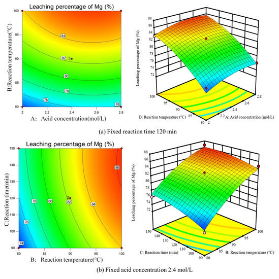
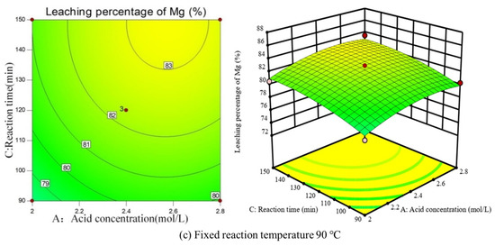
Figure 6.
The 3D plots and contour plots showing the effect of (a) acid concentration and reaction temperature, (b) reaction temperature and reaction time, and (c) reaction time and acid concentration.
The most suitable conditions for primary acid leaching recommended by the response surface method are: acid concentration of 2.44 mol/L, reaction temperature of 96.11 °C, reaction time of 116.15 min, and the predictive leaching rate of magnesium is 84.68%. Considering the convenience of practical operation, the optimal process conditions were adjusted as follows: acid concentration of 2.4 mol/L, reaction temperature of 96 °C, and reaction time of 116 min. The average leaching percentage of magnesium was 84.97% after three replicate validation experiments. Secondary leaching of the primary residue was also carried out, and the comprehensive Mg leaching percentage of FNS reached 95.82%. The optimization was appreciable.
3.4. Analysis of Leaching Kinetics
Visual observations from the experiments showed that the leaching process followed the shrinkage-nuclear-reaction model. According to the leaching rate with reaction time at different reaction temperatures experimental data, the kinetics of magnesium leaching is analyzed, as shown in Figure 7a. Therefore, under the assumption that the sample is a homogeneous spherical solid phase, the chemical-reaction-controlled and diffusion-controlled models can be represented by the following equations [37,38]:
where α is the leaching efficiency of magnesium, %, t is the leaching time, min, k1 is the chemical reaction rate constant, min−1, and k2 is the apparent rate constant of the internal diffusion-controlled model, min−1.
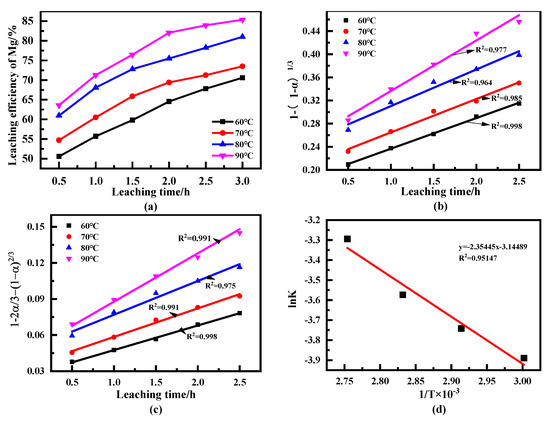
Figure 7.
(a) Relationship between Mg leaching efficiency and leaching time; (b) plots of 1 − (1 − α)1/3 vs. time for magnesium leaching; (c) plots of 1 − 2α/3 − (1 − α)2/3 vs. time for magnesium leaching; (d) Arrhenius plot of the solid membrane diffusion-controlled model.
The curves in Figure 7b exhibit a higher degree of deviation, indicating that the magnesium leaching process does not agree with the chemical reaction-controlled model. As shown in Figure 7c, during the initial 2.5 h leaching process, four straight lines that approach the zero point are observed, which are closer to the origin at low temperature (60 °C) and deviate from the origin at high temperature, demonstrating that the extraction is more likely controlled by diffusion through the solid membrane.
To calculate the activation energy of magnesium leaching, the Arrhenius equation was applied [39]:
where K is the reaction rate constant, min−1, E is the activation energy, J·mol−1, T is the reaction temperature, K, R is the gas constant with a value of 8.314 J·K−1·mol−1, and A is the frequency factor.
A plot of lnK vs. 1/T for the diffusion-controlled model is linear, as presented in Figure 7d. The apparent activation energy (E) of 19.57 kJ·mol−1 was calculated from the slope of the line. It is inferred that the magnesium leaching process obeys composite control [39]. At low temperatures, the acid leaching reaction rate is slower and mainly controlled by chemical reactions. When the temperature rises to a certain value, the chemical reaction rate increases, resulting in an increase in the thickness of the product layer; the control step changes from chemical control to solid film diffusion control (mainly manifested as internal diffusion control). Therefore, thinning the solid film or accelerating the diffusion, such as by increasing the lixiviant concentration or decreasing the particle size of the solid, can be used to enhance the extraction of magnesium.
3.5. Purification of Magnesium
The two-stage acid leachates were mixed, and their metal ion composition is shown in Table 6. Besides Mg2+, the leaching solution contains Fe2+/Fe3+, Al3+, and Cr2+, which are impurities in the preparation of magnesium products. The quality of magnesium product vitally depends on the purity of the magnesium in the leachate; therefore, impurities should be removed as much as possible. Precipitation is a traditional impurity removal method; the theoretical basis is that different ions will be converted to metal hydroxide precipitation at different pH values of the solution, as shown in Table 7 [32]. Irons such as Fe3+, Al3+, and Cr3+ are relatively easy to be separated with Mg2+ due to their large and varying precipitation pH values, while Fe2+ and Mn2+ prevent the purification and recovery of Mg, since the precipitation pH values of Fe2+ and Mn2+ overlap with that of Mg2+. Considering the low content of impurities, except for Fe, it is difficult to remove all of them sequentially and the cost is high. Therefore, centralized removal is adopted in this study. Fe2+ and Mn2+ were first oxidized to Fe3+ and MnO2 with H2O2, then the leachate pH value was gradually adjusted to 7 by aqueous ammonia. Accordingly, most of the foreign ions could be separated as sediments from Mg2+, which remained in the liquid. Following this, the leachate underwent deep impurity removing by optimizing the pH value, react temperature, and time. The results are shown in Figure 8.
Table 6.
Metal ion concentrations in leachates (g/L).
Table 7.
pH of different metal ions upon hydroxide precipitation (25 ℃).
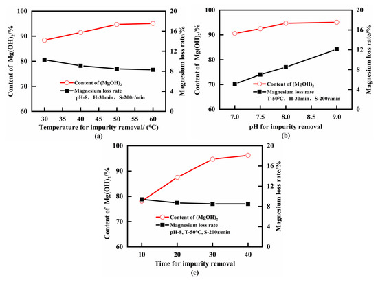
Figure 8.
Impurity removal results of acid leachate (a) temperature for impurity removal; (b) pH for impurity removal; (c) time for impurity removal.
As shown in Figure 8a, increasing the reaction temperature can accelerate the precipitation and promote the generation of large-scale precipitates, thereby reducing the adsorption of Mg2+ by the precipitates and improving the subsequent solid-liquid separation effect. Thus, with the reaction temperature increase, Mg loss decreases, and the content of the intermediate product of Mg(OH)2 increases. However, this effect became considerably weak after 50 °C. Therefore, the appropriate temperature for impurity removal was 50 °C.
Figure 8b illustrates that the pH value of the solution should be modest—the impurity ion precipitated incompletely at a lower pH, resulting in a lower Mg(OH)2 content. Furthermore, when the pH was too high, a large amount of Mg2+ precipitated and the Mg loss in the solution increased. The optimum pH value for impurity removal was 8.0.
From Figure 8c, it can be concluded that the impurity removal time affected the sedimentation of impurity ions while having minimal effect on the Mg loss rate. The Mg(OH)2 content decreased when the removal time was no longer enough—owing to incomplete precipitation of impurity ions and large amounts of impurity ions remaining in the magnesium sulfate solution. After 30 min of impurity removal, the Mg(OH)2 content tended to be stable; therefore, the impurity removal time was fixed at 30 min.
The chemical composition of the impurity removal residue is summarized in Table 8 after deep impurity removal under the above optimum conditions. The metal ion concentration of leachate after metal purification is shown in Table S1. It is shown that Fe, Al, Cr, and other elements are enriched in the debris, which creates conditions for their progressive recovery and utilization. After deep purification, the content of the intermediate product Mg(OH)2 of magnesium sulfate was 95.10%, and the Mg loss rate was 8.5%
Table 8.
Elemental composition of impurity removal residue (%).
3.6. Preparation of Magnesium Oxide
The alkaline magnesium carbonate calcination process was used to overcome the problems of high S content and bulk density of MgO products prepared by the conventional magnesium hydroxide calcination process [34]. Figure 9 illustrates the effect of the main technological conditions on the preparation of basic magnesium carbonate from purified magnesium sulfate solution.
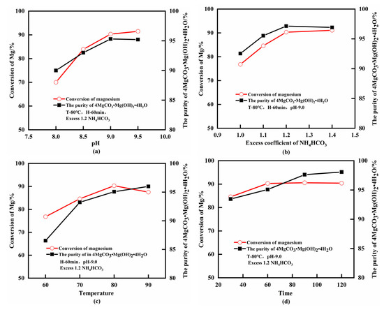
Figure 9.
Effect of the main process conditions on magnesium precipitation efficacy (a) pH; (b) excess coefficient of NH4HCO3; (c) temperature; (d) time. The purity of the precipitated products was calculated by the content of Mg found in the obtained precipitate vs the theoretical amount of Mg in 4MgCO3•Mg(OH)2•4H2O.
The Mg conversion rate and purity of the precipitated products gradually increased with the increase in pH value. When the pH reached 9.0, the Mg conversion rate was 90.3%, and the purity of the product was 95.08%. Continuously increasing pH resulted in a slight increase in Mg conversion but a decrease in product purity (Figure 9a), indicating that low pH and an insufficient amount of ammonia led to incomplete precipitation of Mg2+, low product purity, and Mg conversion. However, if the pH is large enough, increasing the ammonia dosage will again promote the production of Mg(OH)2 precipitate (milk-white precipitate has been observed at pH = 9.5), and the adsorption of ions in the solution by Mg(OH)2 exist in colloidal form, which will affect the production and quality of basic magnesium carbonate, which is also unfavorable to the subsequent product filtration and washing [34]. The optimal pH was determined to be 9.0, corresponding to an ammonia addition of 2 mL.
The effect of the NH4HCO3 content on the production of basic magnesium carbonate is shown in Figure 9b. When the excess coefficient of NH4HCO3 is 1.0–1.2, purity and magnesium conversion of the precipitates increase with the excess coefficient. Moreover, when the excess coefficient reached 1.3, the purity in the precipitates decreased and the magnesium conversion was basically unchanged. It can be observed that sufficient NH4HCO3 is a necessity for the complete conversion of Mg2+ into basic magnesium carbonate; however, when NH4HCO3 is in excess, it causes incomplete dissolution, which is unfavorable to the reaction. Therefore, an excess coefficient of 1.2 was chosen for NH4HCO3.
Figure 9c shows that the magnesium precipitation reaction needs to be carried out at a certain temperature. Low temperature led to a slow reaction speed, and ammonia volatilized retarding the reaction when the temperature was too high (Equation (5)). In addition, the formation of basic magnesium carbonate was hindered due to a portion of Mg2+ converting to Mg(HCO3)2 or MgCO3•3H2O [34]. These all led to a decrease in Mg conversion and product purity; therefore, 80 °C is the comparative suitable reaction temperature.
The results shown in Figure 9d suggest that increasing the reaction time had a beneficial effect on the purity of the product and the conversion of magnesium; however, the effect on the product’s purity was more obvious. After 60 min reaction, the Mg2+ in the solution completely participated in the reaction, and the Mg conversion no longer changed. When the reaction time was continued to 90 min, and the reaction was dominated by the conversion of intermediate products such as Mg(HCO3)2 or MgCO3•3H2O rather than basic magnesium carbonate, the purity of the products was further improved. An optimal reaction time of 90 min was experimentally determined.
In summary, the purity of the magnesium precipitation product obtained under optimal conditions was 97.62%, and the Mg conversion rate was 90.6%. The XRD and SEM analysis of magnesium precipitation products are shown in Figure 10. The XRD patterns were in agreement with PDF card 25-0513 (4MgCO3•Mg(OH)2•4H2O), which proved that the product was basic magnesium carbonate. In addition, the intensity of XRD peaks was high and the shape of peaks was sharp, indicating high purity. From the SEM image, it can be clearly seen that this basic magnesium carbonate is a spherical particle with a diameter of about 510 μm; the particle size was uniform, the product was purer, and there were fewer residual impurities on the particle surface. The produced basic magnesium carbonate can be used as a raw material for the preparation of MgO, and can also be used as a final product with a flexible process.
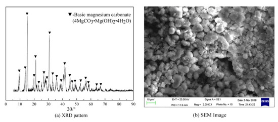
Figure 10.
Analysis of magnesium precipitation product (a) XRD pattern; (b) SEM image.
A powdery material was obtained by calcining the basic magnesium carbonate at 900 °C for 90 min. The color of the powder was white, which is consistent with the appearance characteristics of magnesium oxide. The XRD and SEM of the powder are shown in Figure 11. The XRD pattern was highly consistent with the PDF card -#45-0946 (MgO), and no other impurity peaks were found, indicating that the main chemical composition of the powder was MgO. The SEM images of the powder show that the size of the powder particles is about 2–5 μm with a rod shape, and the surface of the particles is loose, which implies the bulk density of the powder is relatively low. The result of EDS analysis further confirmed that the powder was light magnesium oxide with high purity. Other quality indicators of MgO powder are shown in Table 9. The quality of the powder meets the national industrial magnesium oxide standard, and the profit of this preparation process is considerable (Table S2).
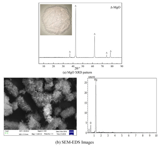
Figure 11.
Analysis of calcined product (a) MgO XRD pattern; (b) SEM-EDS images.
Table 9.
Chinese industry standard for first-class magnesia index and product indexes.
4. Conclusions
The present study proposed a mild and efficient route for the recovery of magnesium from ferronickel slag to prepare magnesium oxide.
(1) The results of the mineralogical analysis showed that the main chemical components of the FNS were SiO2, MgO, and Fe2O3, mainly in forsterite form, with strong crystallinity and leaching out difficulty. The single factor acid leaching experiments showed that grinding fineness, acid concentration, liquid-to-solid ratio, leaching temperature, leaching time, and stirring speed all had an impact on the leaching of Mg. The influence of acid leaching temperature, acid leaching time, and acid concentration were more prominent. The maximum leaching rate of Mg in the primary acid leaching was 82.05% and increased by 12.24% after the secondary acid leaching. Therefore, a two-step leaching process is recommended.
(2) The response surface analysis showed that when the sulfuric acid concentration was controlled above 2 mol/L, the degree of influence of the following three factors on the magnesium leaching rate were: reaction temperature > reaction time > acid concentration. In addition, there is a certain interaction between the leaching temperature and the leaching time. Combining the single factor experiment with response surface optimization, the optimum process conditions for acid leaching are as follows: in the two-step leaching process, the FNS grinding fineness of −0.074 mm accounted for 94.5%, the acid concentration was 2.4 mol/L, the leaching temperature was 96 °C, and the stirring speed was 200 r/min; the liquid-to-solid ratios in the primary and secondary processes were 6 mL/g and 3 mL/g; the leaching times in the first and second stage were 120 min and 150 min, respectively. The comprehensive magnesium leaching rate from ferronickel slag reached 95.82% (84.97% for primary leaching and 72.19% for secondary leaching).
(3) The acid leaching kinetics study showed that the atmospheric sulfuric acid leaching of magnesium from FNS satisfied the mixed control model. The surface chemical is dominant at low temperatures and turns to film diffusion control at high temperatures. Therefore, reducing the particle size of the FNS and increasing the reaction temperature are important for improving the Mg leaching effect.
(4) Due to the low content of other impurities in the acid leaching solution, (except for Mg), this study prefers to use a centralized exclusion process to remove impurities. After pre-oxidation, pre-purification, and deep impurity removal (50 °C, pH = 8, 30 min) processes, most of the impurities were removed; the content of intermediate product Mg(OH)2 of magnesium sulfate solution was 95.10%, and the Mg loss was 8.5%. Basic magnesium carbonate was prepared by the mixed ammonia precipitation method, and the optimum process conditions were as follows: pH = 9.0, NH4HCO3 excess coefficient of 1.2, 80 °C, 90 min, and the Mg conversion was 90.6%. The results of XRD and SEM analyses showed that the alkali magnesium carbonate obtained in the experiment consisted of spherical particles with a diameter of 5–10 μm, and with high purity (MgO of 42.3%). The white powders obtained by 900 °C roasting 90 min of basic magnesium carbonate are MgO, which is characterized by a diameter of about 2–5 μm, with rod shape and loose surface. The quality of the powder reached the first-grade standard of MgO for industrial use in China.
Supplementary Materials
The following are available online at https://www.mdpi.com/article/10.3390/min11121375/s1, Table S1: metal ion concentrations for the leachate after metals purification (g/L); Table S2: table of economic summary for the treatment of 1 t ferronickel slag.
Author Contributions
Writing, formal analysis, and original draft preparation, J.Y.; conceptualization, review, and revision, X.D.; design and experiments, L.L.; supervision, H.Y.; investigation, X.J. This was a joint work of the five authors; each author was in charge of their expertise and capability. All authors have read and agreed to the published version of the manuscript.
Funding
This research received no external funding.
Acknowledgments
We would like to express our sincere appreciation to the anonymous reviewers for their insightful comments, which helped us improve the quality of this paper. We thanked Tangshan Boquan Industrial Co., Ltd. for its experimental raw materials support in project research.
Conflicts of Interest
The authors declare no conflict of interest.
References
- Luo, J.; Li, G.; Rao, M.; Zhang, Y.; Peng, Z.; Zhi, Q.; Jiang, T. Evaluation of Sintering Behaviors of Saprolitic Nickeliferous Laterite Based on Quaternary Basicity. JOM 2015, 67, 1966–1974. [Google Scholar] [CrossRef]
- Saha, A.K.; Sarker, P.K. Expansion due to alkali-silica reaction of ferronickel slag fine aggregate in OPC and blended cement mortars. Constr. Build. Mater. 2016, 123, 135–142. [Google Scholar] [CrossRef]
- Peng, Z.; Wang, L.; Gu, F.; Tang, H.; Rao, M.; Zhang, Y.; Li, G.; Jiang, T. Recovery of chromium from ferronickel slag: A comparison of microwave roasting and conventional roasting strategies. Powder Technol. 2020, 372, 578–584. [Google Scholar] [CrossRef]
- Zhang, Z.; Zhu, Y.; Yang, T.; Li, L.; Zhu, H.; Wang, H. Conversion of local industrial wastes into greener cement through geopolymer technology: A case study of high-magnesium nickel slag. J. Clean. Prod. 2017, 141, 463–471. [Google Scholar] [CrossRef]
- Saha, A.K.; Sarker, P.K. Sustainable use of ferronickel slag fine aggregate and fly ash in structural concrete: Mechanical properties and leaching study. J. Clean. Prod. 2017, 162, 438–448. [Google Scholar] [CrossRef]
- Choi, Y.C.; Choi, S. Alkali-silica reactivity of cementitious materials using ferro-nickel slag fine aggregates produced in different cooling conditions. Constr. Build. Mater. 2015, 99, 279–287. [Google Scholar] [CrossRef]
- Saha, A.K.; Sarker, P.K.; Golovanevskiy, V. Thermal properties and residual strength after high temperature exposure of cement mortar using ferronickel slag aggregate. Constr. Build. Mater. 2019, 199, 601–612. [Google Scholar] [CrossRef]
- Pan, J.; Zheng, G.L.; Zhu, D.Q.; Zhou, X.L. Utilization of nickel slag using selective reduction followed by magnetic separation. Trans. Nonferrous Met. Soc. China 2013, 23, 3421–3427. [Google Scholar] [CrossRef]
- Komnitsas, K.; Zaharaki, D.; Bartzas, G. Effect of sulphate and nitrate anions on heavy metal immobilisation in ferronickel slag geopolymers. Appl. Clay Sci. 2013, 73, 103–109. [Google Scholar] [CrossRef]
- Ljatifi, E.; Kamusheva, A.; Grozdanov, A.; Paunović, P.; Karamanov, A. Optimal thermal cycle for production of glass–ceramic based on wastes from ferronickel manufacture. Ceram. Int. 2015, 41, 11379–11386. [Google Scholar] [CrossRef]
- Karamanov, A.; Paunović, P.; Ranguelov, B.; Ljatifi, E.; Kamusheva, A.; Načevski, G.; Karamanova, E.; Grozdanov, A. Vitrification of hazardous Fe-Ni wastes into glass-ceramic with fine crystalline structure and elevated exploitation characteristics. J. Environ. Chem. Eng. 2017, 5, 432–441. [Google Scholar] [CrossRef]
- Wang, W.; Chen, J.; Yu, J.; Zhou, L.; Dai, S.; Tian, W. Adjusting the melting and crystallization behaviors of ferronickel slag via partially replacing of SiO2 by B2O3 for mineral wool production. Waste Manag. 2020, 111, 34–40. [Google Scholar] [CrossRef]
- Gu, F.; Peng, Z.; Zhang, Y.; Tang, H.; Ye, L.; Tian, W.; Liang, G.; Rao, M.; Li, G.; Jiang, T. Facile Route for Preparing Refractory Materials from Ferronickel Slag with Addition of Magnesia. ACS Sustain. Chem. Eng. 2018, 6, 4880–4889. [Google Scholar] [CrossRef]
- Peng, Z.; Tang, H.; Augustine, R.; Lee, J.; Tian, W.; Chen, Y.; Gu, F.; Zhang, Y.; Li, G.; Jiang, T. From ferronickel slag to value-added refractory materials: A microwave sintering strategy. Resour. Conserv. Recycl. 2019, 149, 521–531. [Google Scholar] [CrossRef]
- Gu, F.; Peng, Z.; Zhang, Y.; Tang, H.; Tian, W.; Lee, J.; Rao, M.; Li, G.; Jiang, T. Promoting spinel formation and growth for preparation of refractory materials from ferronickel slag. Int. J. Appl. Ceram. Technol. 2020, 17, 1701–1712. [Google Scholar] [CrossRef]
- Liu, K. The Study on the Preparation of Forsterite Refractories from High Magnesium Nickel Slag; University of Science and Technology: Beijing, China, 2018; pp. 1–76. [Google Scholar]
- Wang, Y.; Zhu, R.; Chen, Q.; Wei, G.; Hu, S.; Guo, Y. Recovery of Fe, Ni, Co, and Cu from nickel converter slag through oxidation and reduction. ISIJ Int. 2018, 58, 2191–2199. [Google Scholar] [CrossRef]
- Huang, F.; Liao, Y.; Zhou, J.; Wang, Y.; Li, H. Selective recovery of valuable metals from nickel converter slag at elevated temperature with sulfuric acid solution. Sep. Purif. Technol. 2015, 156, 572–581. [Google Scholar] [CrossRef]
- Tian, D.; Shen, X.; Zhai, Y.; Xiao, P.; Webley, P. Extraction of iron and aluminum from high-iron bauxite by ammonium sulfate roasting and water leaching. J. Iron Steel Res. Int. 2019, 26, 578–584. [Google Scholar] [CrossRef]
- Zhai, X.J.; Li, N.J.; Zhang, X.; Fu, Y.; Jiang, L. Recovery of cobalt from converter slag of Chambishi Copper Smelter using reduction smelting process. Trans. Nonferrous Met. Soc. China 2011, 21, 2117–2121. [Google Scholar] [CrossRef]
- Li, Y.; Perederiy, I.; Papangelakis, V.G. Cleaning of waste smelter slags and recovery of valuable metals by pressure oxidative leaching. J. Hazard. Mater. 2008, 152, 607–615. [Google Scholar] [CrossRef]
- Gbor, P.K.; Ahmed, I.B.; Jia, C.Q. Evaluation of contributions of acid and ligand to Ni, Co, and Fe dissolution from nonferrous smelter slags in aqueous sulfur dioxide. Ind. Eng. Chem. Res. 2002, 41, 1861–1867. [Google Scholar] [CrossRef]
- Perederiy, I.; Papangelakis, V.G.; Buarzaiga, M.; Mihaylov, I. Co-treatment of converter slag and pyrrhotite tailings via high pressure oxidative leaching. J. Hazard. Mater. 2011, 194, 399–406. [Google Scholar] [CrossRef] [PubMed]
- Curlook, W.; Baghalha, M.; Papangelakis, V.; Curlook, W.; Baghalha, M.; Papangelakis, V. Process for the Recovery of Residual Metal Values from Smelter Waste Slags, and from Converter Slags. CA2363969 C, 13 January 2001. [Google Scholar]
- Altinkaya, P.; Mäkinen, J.; Kinnunen, P.; Kolehmainen, E.; Haapalainen, M.; Lundström, M. Effect of biological pretreatment on metal extraction from flotation tailings for chloride leaching. Miner. Eng. 2018, 129, 47–53. [Google Scholar] [CrossRef]
- Bulaev, A.G.; Muravyov, M.I.; Pivovarova, T.A.; Fomchenko, N.V.; Kondrat’eva, T.F. Bioprocessing of mining and metallurgical wastes containing nonferrous and precious metals. Adv. Mater. Res. 2013, 825, 301–304. [Google Scholar] [CrossRef]
- Zhang, X.; Gu, F.; Peng, Z.; Wang, L.; Tang, H.; Rao, M.; Zhang, Y.; Li, G.; Jiang, T.; Wang, Y. Recovering Magnesium from Ferronickel Slag by Vacuum Reduction: Thermodynamic Analysis and Experimental Verification. ACS Omega 2019, 4, 16062–16067. [Google Scholar] [CrossRef]
- Zhao, C.; Cai, Y.; Ning, Z.; Wang, G.; Kang, S.; Zhang, C.; Zhai, Y. Recovery of MgO from laterite nickel slag through roasting by ammonium sulfate. Zhongnan Daxue Xuebao (Ziran Kexue Ban)/J. Cent. South Univ. (Sci. Technol.) 2017, 48, 1972–1978. [Google Scholar] [CrossRef]
- Prasetyo, A.B.; Rahadian, D.; Mayangsari, W.; Febriana, E.; Permana, S.; Maksum, A.; Soesaptri, O.; Firdiyono, F.; Soedarsono, J.W. Reverse leaching of magnesium from ferronickel slag using alkali solvent naoh. Eastern-Eur. J. Enterp. Technol. 2020, 1, 6–14. [Google Scholar] [CrossRef][Green Version]
- Mubarok, M.Z.; Yudiarto, A. Synthesis of Magnesium Oxide from Ferronickel Smelting Slag through Hydrochloric Acid Leaching-—Precipitation and Calcination; Springer: Berlin/Heidelberg, Germany, 2017. [Google Scholar]
- Gao, F.; Huang, Z.; Li, H.; Li, X.; Wang, K.; Hamza, M.F.; Wei, Y.; Fujita, T. Recovery of magnesium from ferronickel slag to prepare hydrated magnesium sulfate by hydrometallurgy method. J. Clean. Prod. 2021, 303, 127049. [Google Scholar] [CrossRef]
- Linchuan, L. The Study on the Comprehensive Utilization and Recovery of Valuable Components from Electric Furnace Nickel-Iron Slag. Master’s Thesis, University of Science and Technology, Beijing, China, 2018; pp. 1–79. [Google Scholar]
- Bergmann, J.; Friedel, P.; Kleeberg, R. BGMN—A New Fundamental Parameters Based Rietveld Program for Laboratory X-ray Sources, it’s Use in Quantitative Analysis and Structure Investigations. IUCr Comm. Powder Diffr. Newsl. 1998, 20, 5–8. [Google Scholar]
- Xu, H.; Liu, W.P.; Yang, X.Y.; Shi, X.C.; Chen, S.Y.; Yu, L.L. Preparation of high-purity light magnesia from sulfate salt subtype salt lake brine. Zhongnan Daxue Xuebao (Ziran Kexue Ban)/J. Cent. South Univ. (Sci. Technol.) 2011, 42, 2204–2208. [Google Scholar]
- Huang, J.; Chen, M.; Chen, H.; Chen, S.; Sun, Q. Leaching behavior of copper from waste printed circuit boards with Brønsted acidic ionic liquid. Waste Manag. 2014, 34, 483–488. [Google Scholar] [CrossRef] [PubMed]
- Khatoon, H.; Rai, J.P.N. Optimization studies on biodegradation of atrazine by Bacillus badius ABP6 strain using response surface methodology. Biotechnol. Rep. 2020, 26, e00459. [Google Scholar] [CrossRef] [PubMed]
- Apostolidis, C.I.; Distin, P.A. The kinetics of the sulphuric acid leaching of nickel and magnesium from reduction roasted serpentine. Hydrometallurgy 1978, 3, 181–196. [Google Scholar] [CrossRef]
- Hollagh, A.R.E.; Alamdari, E.K.; Moradkhani, D.; Salardini, A.A. Kinetic Analysis of Isothermal Leaching of Zinc from Zinc Plant Residue. Int. J. Nonferrous Metall. 2013, 2, 10–20. [Google Scholar] [CrossRef][Green Version]
- Lin, Q.; Gu, G.; Wang, H.; Zhu, R.; Liu, Y.; Fu, J. Preparation of manganese sulfate from low-grade manganese carbonate ores by sulfuric acid leaching. Int. J. Miner. Metall. Mater. 2016, 23, 491–500. [Google Scholar] [CrossRef]


Publisher’s Note: MDPI stays neutral with regard to jurisdictional claims in published maps and institutional affiliations. |
© 2021 by the authors. Licensee MDPI, Basel, Switzerland. This article is an open access article distributed under the terms and conditions of the Creative Commons Attribution (CC BY) license (https://creativecommons.org/licenses/by/4.0/).