Abstract
The bed pressure drop, minimum fluidized gas velocity, bed density, and bed expansion rate are important parameters characterizing the fluidization characteristics of gas-solid fluidized beds. By analyzing these parameters, the advantages and disadvantages of the fluidization state can be known. In this study, experiments were conducted to study the fluidization characteristics of a gas-solid magnetically fluidized bed for microfine particles by changing the magnetic field strength, magnetic field addition sequence, and static bed height. The experimental results show that when the magnetic field strength increased from 0 KA/m to 5 KA/m, the minimum fluidized gas velocity of particles increased from 4.42 cm/s to 10.32 cm/s, while the bed pressure drop first increased and then decreased. When the magnetic field strength is less than 3.4 KA/m, the microfine particles in the bed are mainly acted on by the airflow; while when the magnetic field strength is greater than 3.4 KA/m, the microfine particles are mainly dominated by the magnetic field. The magnetic field addition sequence affects the fluidization quality of microfine particles. The fluidized bed with ‘adding magnetic field first’ shows a more stable fluidization state than ‘adding magnetic field later’. Increasing of the static bed height reduces the bed expansion rate. The bed expansion rate is up to 112.5% at a static bed height of h0 = 40 mm and H = 5 KA/m. This will broaden the range of density regulation of a single magnetic particle and lay the advantage of gas-solid magnetically fluidized bed for microfine particles in the field of separation of fine coal.
1. Introduction
Fluidization technology allows solid particles to become quasi fluids under the action of airflow and have the properties of a fluid [1,2]. Fluidized bed technology is widely used in the energy and chemical industries [3,4,5,6]. In the field of coal sorting, the air-heavy media fluidized bed dry coal sorting technology is a new and efficient sorting technology that applies gas-solid fluidization technology to coal sorting, with the advantages of high sorting accuracy and low processing cost. The China University of Mining and Technology was the first to conduct a sorting test of air-heavy media fluidized bed for coal with a particle size of 100–6 mm [7,8]. Researchers in Canada and Japan have also conducted research related to air-heavy media fluidized bed coal separation technology [9,10]. The sorting medium of air-heavy media fluidized bed dry coal separation technology is a binary weighted composition of magnetite powder (<0.3 mm) and coal powder (<1.0 mm), and the lower limit of sorting particle size for coal is 6 mm [11,12,13]. The sorting of coal is related to the media size and fluidization quality, and to solve the sorting problem of coal below 6 mm, it is usually necessary to improve the fluidization quality as well as to use finer size magnetic particles [14,15].
Geldart proposed a classification of particles into four types, A, B, C, and D, based on the difference between particles’ apparent density and gas density and the difference in particle size [16]: the particle size of class A is 20–100 μm, and it is easy to re-mix when its mixing degree is high. The particle size of class C is usually less than 20 μm, and it is generally difficult to fluidize normally, and the particles occur easily when fluidizing. The particles are prone to agglomeration and other phenomena during fluidization, accompanied by abnormal fluidization phenomena such as channel flow and piston flow. The fluidization quality of fluidized beds depends on bed stability and homogeneity, which can be improved and enhanced by introducing external energy (vibrational field, pulsating field, magnetic field, acoustic field, centrifugal field, etc.) for fine-grained magnetic particles (Geldart A and Geldart C class particles) [17,18,19,20,21,22,23,24]. Among these techniques, the introduction of magnetic field energy into fluidization and its application to coal sorting has been extensively studied [25].
The results of Rosensweig’s experiments showed that in a homogeneous magnetically fluidized bed, the magnetic field only induces interacting magnetic forces between particles and does not produce any bulk force on a single particle [26,27]. Pinto-Espinoza investigated the forces on particles in a magnetically fluidized bed and established the magnetic chain (Chain-like agglomerates formed by magnetic particles under the action of a magnetic field) gravitational relationship [28]. The study of magnetic chain agglomerates by Lu showed that particles in a magnetically fluidized bed changed the minimum fluidized gas velocity due to changes in the applied magnetic field, and established the model of minimum fluidized gas velocity of the magnetic chain [29]. This indicates that the magnetic field fluidization of magnetic particles can be achieved and that the basic fluidization properties should be extensively studied and advanced. Zhu Qingshan studied the magnetic fluidization of Geldart C particles and stated that the magnetic field can effectively eliminate the channel flow within the fluidized bed, enabling a stable fluidization operation of fine particles [30]. Song Shulei used 0.045–0.074 mm particle size magnetite powder and magnetic beads for magnetic field fluidized bed experiments, and the results showed that the magnetic field gas-solid fluidized bed has a wider range of stable operating gas velocity than the normal gas-solid fluidized bed [31]. Luo Zhenfu used magnetite powder of 0.043–0.074 mm as separation media to separate fine coal, and the lower limit of size of the separated material was 0.5 mm [32]. All of the above studies show that the external magnetic field can assist the fine particles to reach the normal fluidization state and improve the fluidization quality, but the influence of the magnetic field on the fluidization process itself has several drawbacks, including the action mechanism of a uniform magnetic field on magnetic particles in a gas-solid fluidized bed, and there are few reports on the sorting of fine-grained magnetic fluidized beds for coal below 0.5 mm. In this study, Geldart A + C magnetite powder was used for fluidization experiments to study the differences in fluidization characteristics at different magnetic field strengths (H), static bed heights (h0), and magnetic field addition sequences, and the two different effects of the magnetic field are investigated to provide a theoretical basis for the sorting of fine particle (less than 0.5 mm) coal by a fine particle gas-solid magnetic fluidized bed.
2. Materials and Methods
2.1. Materials
The experimental magnetite powder particle sizes range from 0.01 to 0.045 mm, the real density of magnetite powder is about 5000 kg/m3 and the bulk density is about 2400 kg/m3. The particle size distribution is shown in Table 1, which is a mixture of Geldart A and Geldart C type particles.

Table 1.
Size distribution of magnetite powder.
2.2. Experimental System and Research Methods
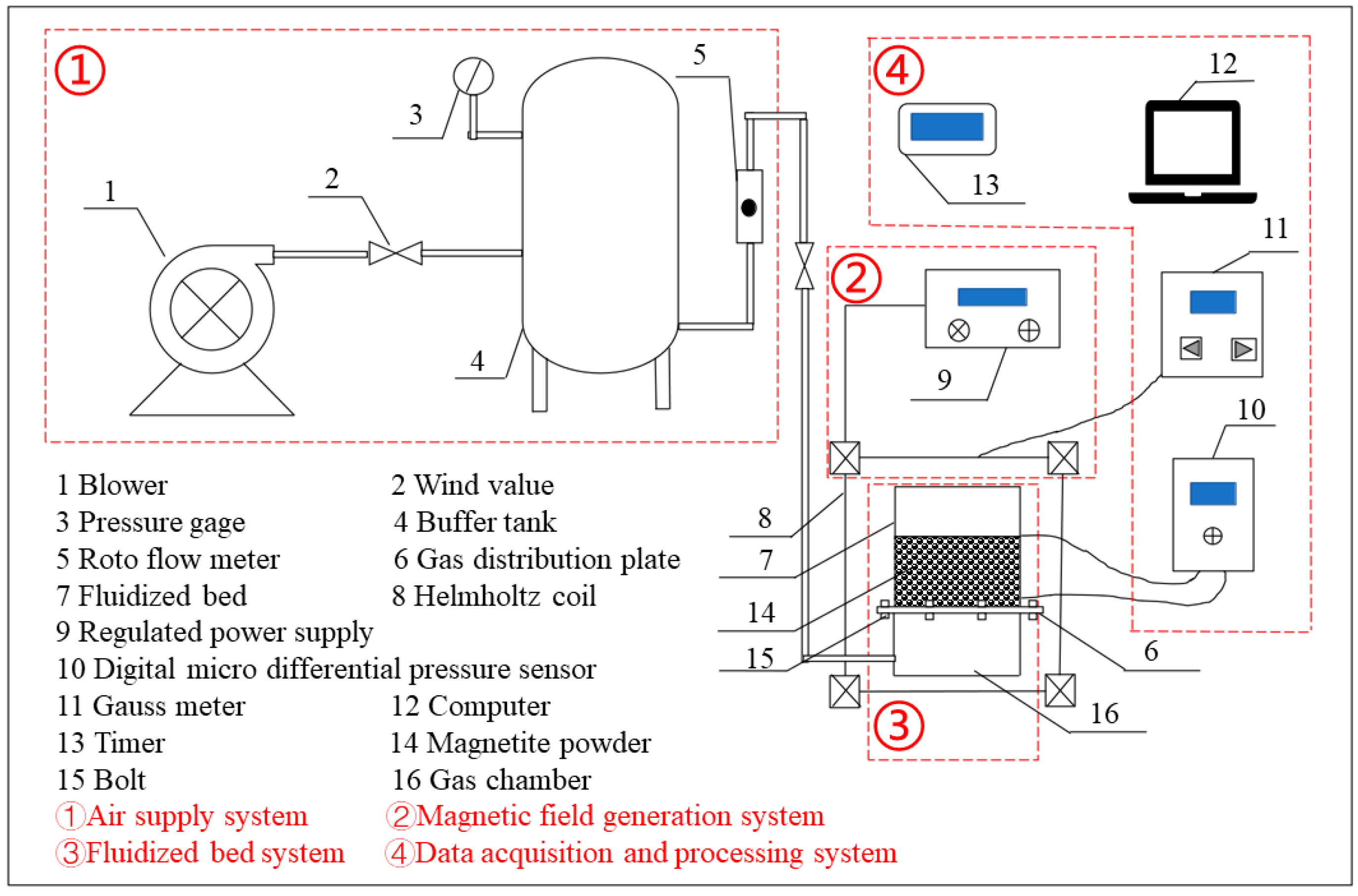
As shown in Figure 1, the experimental system consists of four parts, which are the air supply system, magnetic field generation system, fluidized bed system, and data acquisition and processing system. The air supply system includes a blower and a storage tank, the magnetic field generation system includes a regulated power supply and a Helmholtz coil, the fluidized bed system consists of a plexiglass bed and a cloth air plate, and the data acquisition and processing system includes a timer, a Gauss meter, and a digital microscopic differential pressure sensor. The fluidized bed system consists of a gas chamber, an air distributor, and a plexiglass cylindrical bed. The air chamber and air plate are made of non-magnetic stainless steel. The air plate is covered with filter cloth. The inner diameter of the bed is 120 mm and the height is 140 mm. The gas flow into the fluidized bed is controlled by adjusting the air valve of the rotameter. Compared with the ordinary fluidized bed, this system adds a magnetic field generation system, which aims to weaken the adhesion and trench retention of microfine particles in the fluidized bed and improve the fluidization performance of the bed. The magnetic field generation system is powered by a regulated power supply, which provides a stable current to the Helmholtz coil when the ‘output voltage’ switch is pressed, thus generating a stable magnetic field in the coil. The magnetic field strength can be adjusted from 0 to 24 KA/m. The magnetic field can have a magnetic effect on the microfine particles. Digital micro differential pressure sensors are used to measure the bed pressure drop (ΔP), then data is analyzed and processed by a computer.
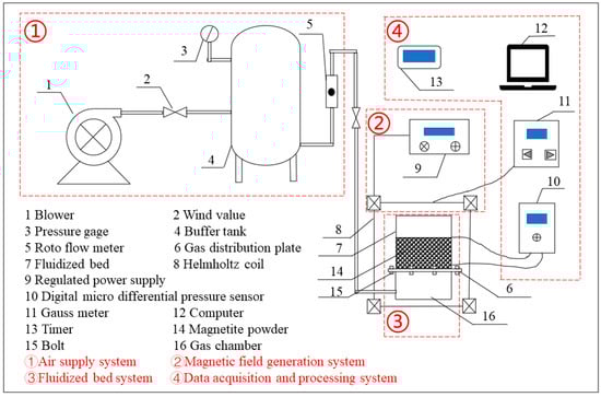
Figure 1.
Testing system of the magnetic field fluidization for microfine particles.
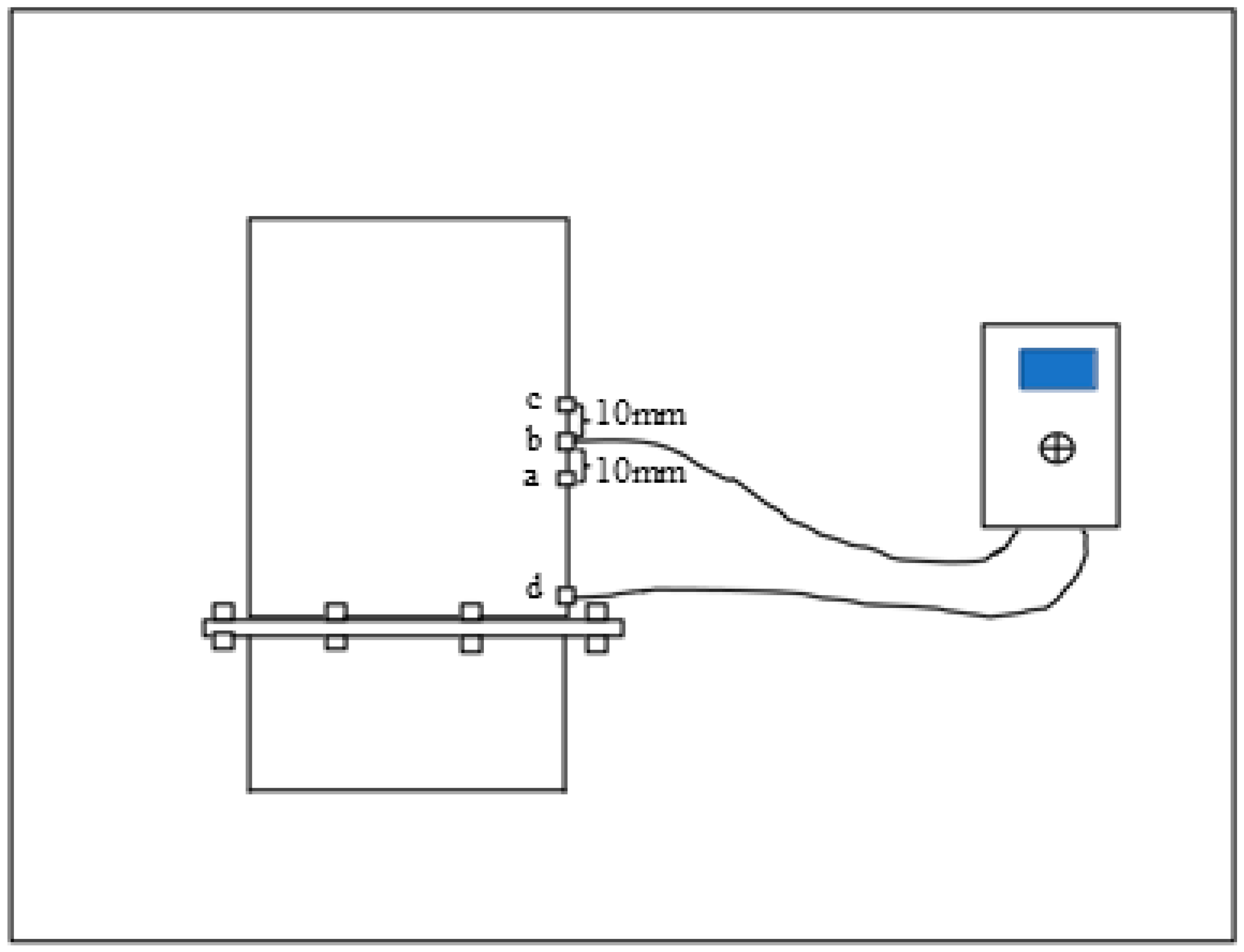
The experiments were carried out at a temperature of 25 °C. The measurement points of pressure drop are shown in Figure 2 as a (when the static bed height is 40 mm), b (when the static bed height is 50 mm), c (when the static bed height is 60 mm), and d. To study the difference in fluidization characteristics of microfine particles under different magnetic field conditions, the static bed height is set to 40 mm, 50 mm, and 60 mm respectively, and the magnetic field strength is changed by adjusting the voltage of the regulated power supply, and the magnetic field strength is set to 0 KA/m, 1 KA/m, 2 KA/m, 3 KA/m, 4 KA/m, and 5 KA/m respectively. The gas velocity (0 to 12.80 cm/s) was adjusted by adjusting the rotameter gas valve, and the bed pressure drop values were recorded at each magnetic field strength. To investigate the effect of static bed height on the minimum fluidization gas velocity (Umf) and bed expansion rate (ε) of particles, the static bed height was 40 mm, 50 mm, and 60 mm, respectively, and the gas velocity and magnetic field strength were adjusted to record the bed pressure drop values and bed height under different static bed height conditions. ‘Adding the magnetic field first’ means that a stable magnetic field is added to the bed before the particles are fluidized, and ‘adding the magnetic field later’ means that the voltage regulator is set at a specific voltage before the particles are fluidized. To investigate the effect of the order of magnetic field addition on the fluidization state of the particles. In the ‘adding the magnetic field first’ procedure, the regulated power supply is switched on to provide a stable magnetic field to the bed, the rotameter gas valve is opened to adjust the gas velocity, and the pressure drop at different gas velocities is measured with a digital micro differential pressure sensor. Then the pressure drop value is measured under the condition of ‘adding the magnetic field later’, first pass the airflow to the bed to make the particles in fluidization, and then turn on the “output voltage” switch after 30 s, the bed will be instantaneously subjected to the action of the applied magnetic field. Observe the experimental phenomena and record the changes of the bed and the pressure drop with time.

Figure 2.
Pressure measurement point.
3. Results and Discussion
3.1. Magnetic Fluidization Characteristics of Microfine Particles
3.1.1. Effect of Magnetic Field Strength on Bed Pressure Drop
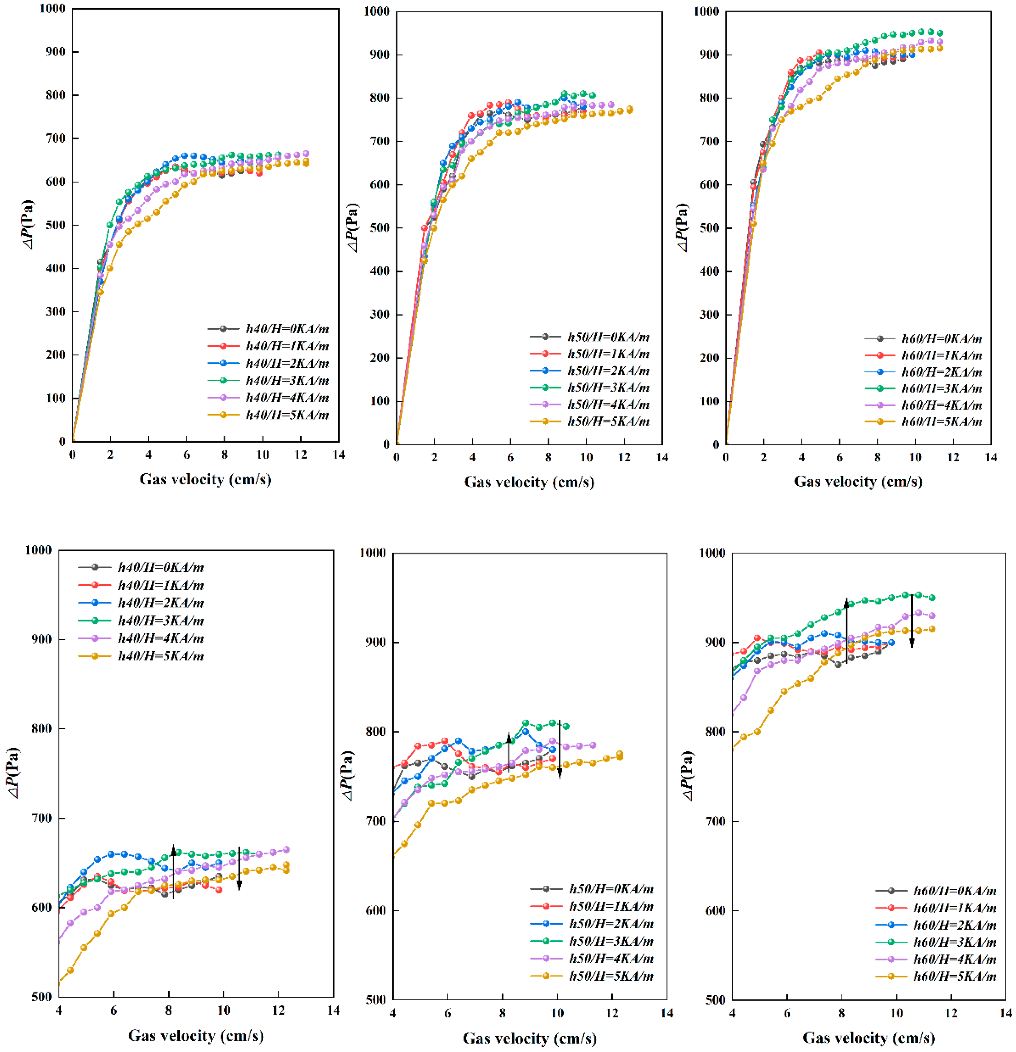
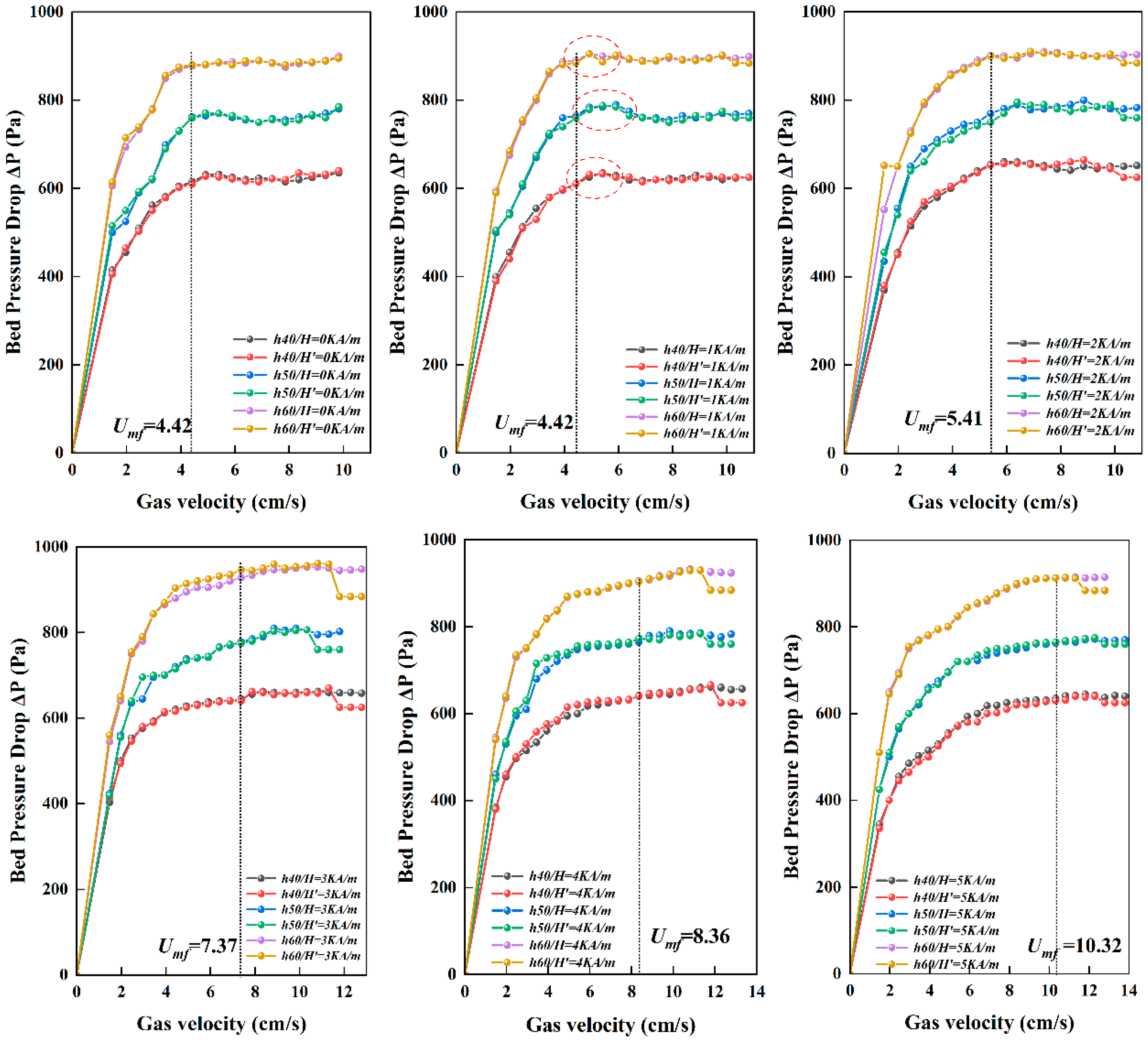
The bed pressure drop was measured by the “deceleration method”, i.e., the gas velocity was gradually reduced from 12.80 cm/s to 0 cm/s. Figure 3 shows the fluidization characteristics curve of the particles when the magnetic field strength was varied. The analysis shows that the bed pressure drop increases with the increase of the static bed height, the introduction of the magnetic field will have an effect on the bed pressure drop. The overall pressure drop of the bed is increased with the increase of the static bed height. With the gradual increase of the applied magnetic field strength, the overall pressure drop of the bed first increases and then decreases (see Appendix A). When the magnetic field strength H = 1 KA/m, 2 KA/m, 3 KA/m, the bed pressure drop gradually increases, and the overall bed pressure drop is higher than the bed pressure drop at H = 0 KA/m. While H = 4 KA/m and 5 KA/m, the bed pressure drop decreases compared with the bed pressure drop when H = 1 KA/m, 2 KA/m, 3 KA/m.
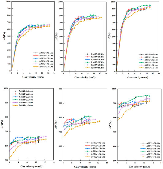
Figure 3.
Fluidization characteristics curves of microfine particles as magnetic field strength changes.
The overall pressure drop of the bed increases when the static bed height changes, which is caused by the increase of the medium in the bed.
When the static bed height is the same, the overall pressure drop of the bed increases and then decreases with the increase of magnetic field strength, which is due to the competition between the applied magnetic field and the gas velocity. Zhu Qingshan et al. proposed to use a dimensionless number Mb to determine whether agglomeration occurs in ferromagnetic materials. When Mb is greater than 2, the ferromagnetic particles in the bed will agglomerate and the bed fluidization state behaves like a dead bed [30]. The expressions are as follows.
Figure 4 shows the results of the analysis of the dimensionless number Mb and the magnetic field strength H at the operating gas velocity of the fluidization number (ratio of operating gas velocity to minimum fluidized gas velocity) N = 1. When the magnetic field strength is equal to 3.4 KA/m, Mb = 1, which means a state of equilibrium. When the magnetic field strength is lower than 3.4 KA/m, Mb < 1, which means that the kinetic energy of the microfine particles is greater than the magnetic energy of the microfine particles. At this point, the existing state of the particles in the bed mainly depends on the role of the gas velocity, and the magnetic field plays an auxiliary role. At H = 1 KA/m, 2 KA/m, and 3 KA/m, the magnetic field strength is less than 3.4 KA/m and Mb is less than 1. This region where Mb is less than 1 is called the magnetically assisted region. Under the ‘magnetic assistance’ of the magnetic field, although the particles in the bed will form a magnetic chain, the strength is very weak. The stability of the magnetic chain is destroyed when it is subjected to the dominant effect of airflow. Thus, the bed competes with the creation and destruction of ‘weak magnetic chains’.
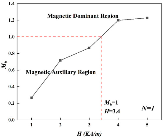
Figure 4.
Curve of Mb versus magnetic field strength H.
During the slow increase of magnetic field strength from zero, Mb gradually increases, so the effect of the magnetic field also increases. Magnetic chains with small scale are generated in the bed, the agglomerations of microfine particles exist at the same time. Zhu Qingshan et al. stated that the needle-like magnetic chains can split the agglomerations of microfine particles into small pieces, i.e., destroy the agglomerations of microfine particles. At H = 1 KA/m, the magnetic chains are easily destroyed by the airflow, so they exhibit a fluidization state similar to that without the magnetic field. It is noteworthy that the peak of the bed pressure drop appears in the low gas velocity stage (such as the position circled by the ellipse in Figure 4, at this time the gas velocity is between 4 cm/s and 6 cm/s), which indicates that magnetic chains are generated in the bed under the low gas velocity condition, and the magnetic chains are not destroyed by the gas flow, and the presence of magnetic chains makes the overall pressure drop of the bed increase.
At H = 2 KA/m and 3 KA/m, the magnetic chains are generated and their number and intensity increase with increasing magnetic field strength. The magnetic chains present in the bed collide with the microfine particle agglomerations, which cause the residual amount of magnetic chains to increase with the increase of magnetic field strength [30]. According to the fractal dimension theory of agglomerations [33], when D is the same value, the magnetic chain structure is smaller, and the fluidity and filling of the magnetic chain itself is not good. The discrete particles in the bed will move to the magnetic chain and fill it, which cause the gas to be difficult to pass through the bed. Consequently, the permeability becomes poor, and the pressure drop rises.
While at H = 4 KA/m and 5 KA/m, the magnetic field strength is greater than 3.4 KA/m and Mb is greater than 1. This indicates that the magnetic energy of the microfine particles is greater than the kinetic energy of the particles, and the effect of the magnetic field is dominant. The region where Mb is greater than 1 is called the magnetic dominant region. At this time, the bed is significantly affected by the magnetic field, and the length and strength of the magnetic chain further increase. In the case of the same fractal dimension, the greater the magnetic field strength, the tighter the structure of the magnetic chains, the better the filling, and the more neat and orderly the arrangement. The permeability of the bed becomes better. Therefore, the overall pressure drop of the bed becomes smaller.
3.1.2. Effect of Adding Sequence of Magnetic Field on Bed Pressure drop
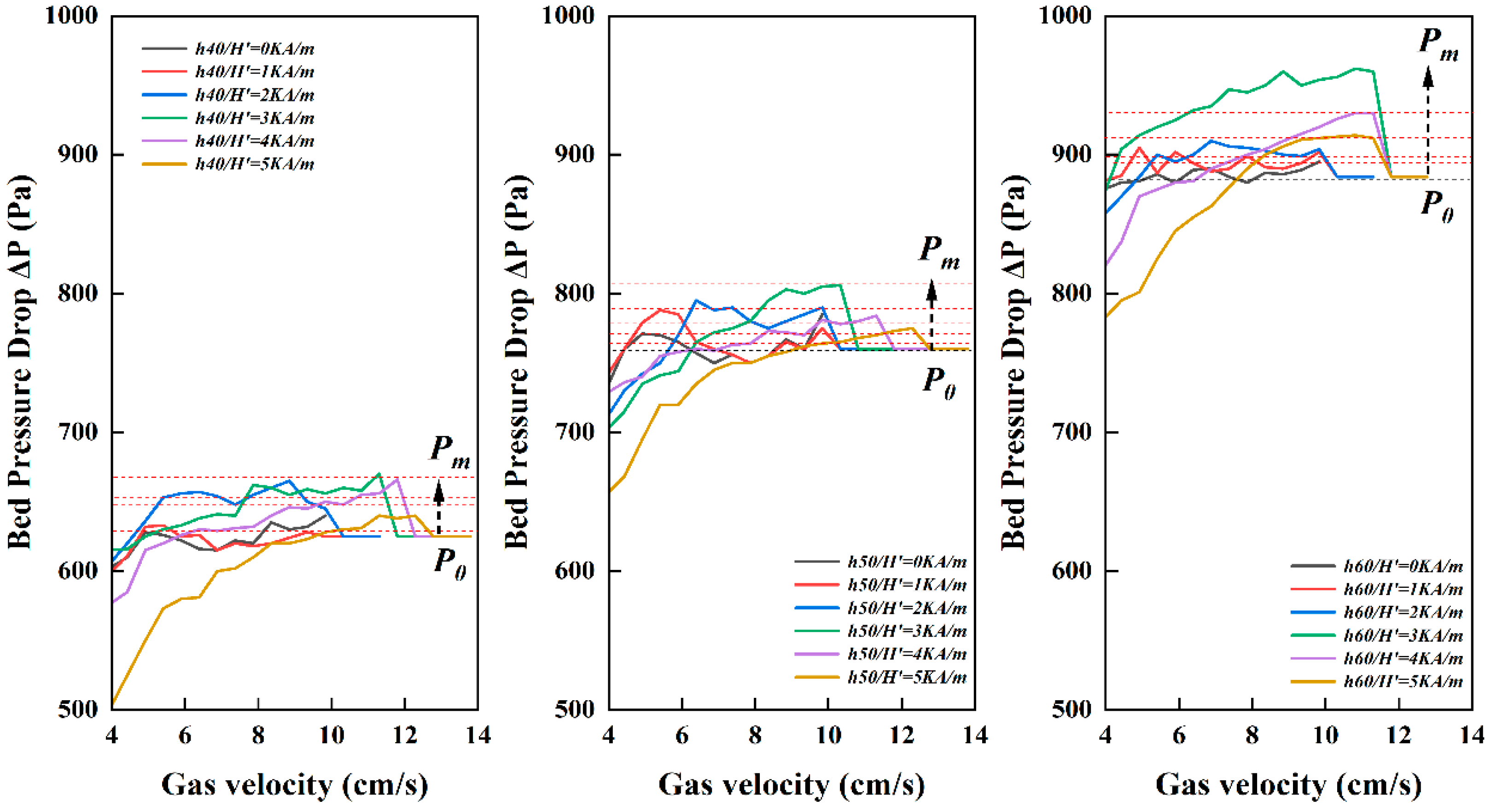
Figure 5 shows the pressure drop curves for different sequences of adding magnetic fields for different static bed height. The experiments show that a phenomenon of ‘sudden change in pressure drop’ occurs in the bed with an ‘adding magnetic field later’ compared to ‘adding magnetic field first’. Figure 6 is the change curve of bed pressure drop under the condition of ‘adding magnetic field later’. When the microfine particles are fluidized without magnetic field, the pressure drop of the bed is stable at P0. With the addition of magnetic field, the pressure drop stabilizes to Pm over time. The variation data are shown in Table 2 (measured when the static bed height is 40 mm).
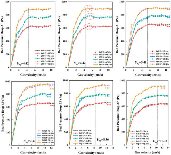
Figure 5.
Particle fluidization curves of different adding sequence of magnetic field.
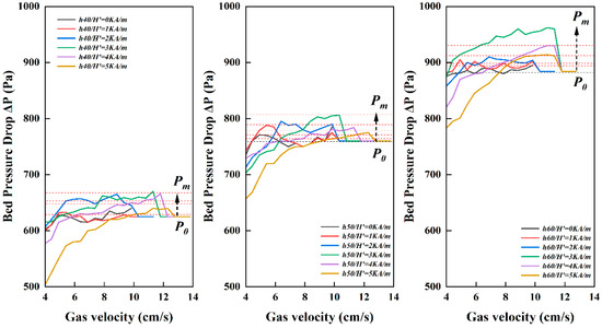
Figure 6.
‘Sudden change of pressure drop’ in the bed of ‘adding magnetic field later’.
Table 2.
Pressure drop change schedule.
With the increase of the magnetic field strength of the ‘adding magnetic field later’, the time required for the ‘sudden change in pressure drop’ decreases. The trend is shown in Figure 7. This is due to the fact that the adding and increase of the magnetic field strength has an effect on the microfine particles in the bed and has an effect on the formation of magnetic chains. The formation of magnetic chains depends on the magnetic field strength, meanwhile the presence of airflow disrupts the formation of magnetic chains. If the magnetic field strength is high, the magnetic chains can be generated and in a stable state in a very short period of time; while the high velocity of airflow can also destroy the structure of the magnetic chains in a very short period of time. In the magnetically dominated region, the magnetic chains can be formed and stabilized in a much shorter time.
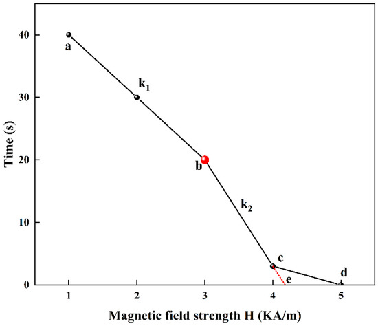
Figure 7.
Pressure drop yield time of ‘adding magnetic field later’. (a–d), are experimental values and e is the predicted value. k1 is the slope of the ab line, k2 is the slope of the bc line, and the absolute value of k2 is greater than the absolute value of k1.
From Figure 7, it can be found that when the magnetic field intensity is greater than 3 KA/m, the absolute value of the slope of the line is greater than that when the magnetic field intensity is less than 3 KA/m. This indicates that the bed is mainly acted by the airflow when the magnetic field strength is less than 3 KA/m, while the bed is mainly acted by the magnetic field when the magnetic field strength is greater than 3 KA/m. Since the time variation at a magnetic field strength of 5 KA/m is not observed, the data of “0 s” is used instead. Accordingly, it can be seen that when the magnetic field strength is between 4 KA/m and 5 KA/m, there exists a value (point e in Figure 7) of magnetic field strength that can cause the microfine particles in the bed to immediately form a chain.
This exactly proves that the above-mentioned speculation of ‘magnetic assist’ and ‘magnetic dominance’ is correct.
3.1.3. Effect of Magnetic Field Strength on the Minimum Fluidized Gas Velocity
In general, the minimum fluidized gas velocity is an inherent property of the particle during fluidization and is related to the nature of the particle, which is fixed [34]. With the addition of a magnetic field, the state of the particles changes, and the minimum fluidized gas velocity also changes [35]. From the analysis of Figure 4, it is clear that the fluidization state of the particles changes when a constant magnetic field is added. The reason for this is that the adding of a magnetic field, on the one hand, causes agglomeration of the microfine particles themselves. On the other hand, it also causes the agglomeration of microfine particles to form magnetic chain agglomerates. In this case, the size of the particles involved in fluidization in the bed has been changed.
When the magnetic field strength is 1 KA/m, the minimum fluidized gas velocity of the particles did not change significantly from that without the magnetic field, which was 4.42 cm/s. This is because, at this time, the magnetic field strength is small, and the magnetic chain strength is weak and easily destroyed by the action of airflow. There is basically no difference between the particles in the bed and when no magnetic field is added, so the minimum fluidized gas velocity basically does not change.
The variation of the minimum fluidized gas velocity increases with the increase of magnetic field strength at the magnetic field strength of 2, 3, 4, and 5 KA/m. The Umf = 10.32 cm/s when H = 5 KA/m. This is because the particles in the bed exist in the form of ‘microfine particle agglomerates-magnetic chains’. With the increase of magnetic field strength, the agglomerates are mainly in the form of magnetic chains. The minimum fluidized gas velocity is different due to the different lengths of the magnetic chains.
It can also be analyzed from Figure 4 that the change in bed height and the different order of magnetic field addition do not change the minimum fluidized gas velocity of the particles.
The analysis of the length of magnetic chains by Qingshan Zhu et al. yielded the following results [36].
And Lu experimentally derived the minimum fluidization velocity model for the magnetic chain as [37].
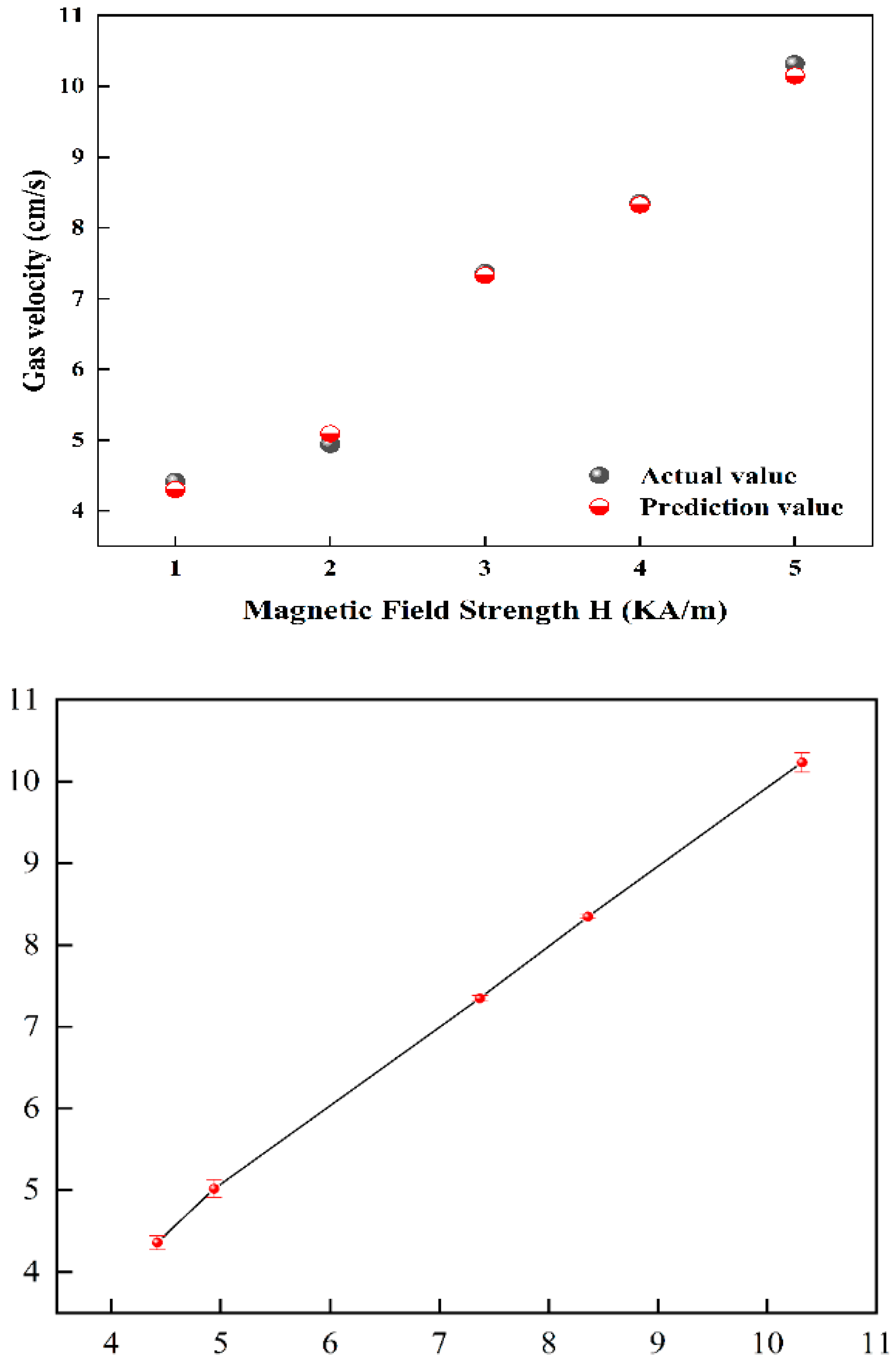
Combining Equations (3) and (4) to verify and parametrically correct the minimum fluidized gas velocity for this experiment, the relationship between the minimum fluidized gas velocity of the magnetic chain and the magnetic field strength under the experimental conditions of this study is obtained as in Equation (5). The comparison of the model predicted values with the actual values and the error analysis are shown in Figure 8.
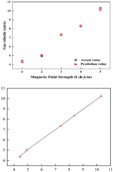
Figure 8.
Minimum fluidized gas velocity model predicted values and error bars.
3.2. Bed Expansion Rate
Figure 9 shows the bed height values and the bed expansion rate at different static bed heights and different magnetic field strengths. When the static bed height and magnetic field strength are constant, the bed height tends to increase with the increase of gas velocity; at the same gas velocity, the bed height also tends to increase with the increase of magnetic field strength. And in the stable fluidization stage, increasing the gas velocity does not change the bed height.
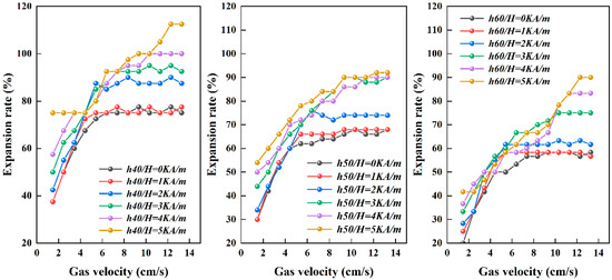
Figure 9.
Bed expansion rate at different static bed heights and different magnetic field strengths.
The reason for this phenomenon is that, on the one hand, during the process of increasing gas velocity, local fluidization of microfine particles in the bed occurs, the bed height and the expansion rate both increase. On the other hand, the adding of magnetic field also cause the particles to form needle-like magnetic chains, especially the uppermost particles, because they are not extruded by other particles, the magnetic chains stretch more freely, thus making the height of the whole bed larger. And with the magnetic field strength increases, the length of magnetic chains becomes larger, the bed height becomes larger, and the bed expansion rate becomes larger. In the stable fluidization stage, the particles are balanced by the forces and the bed height remains constant.
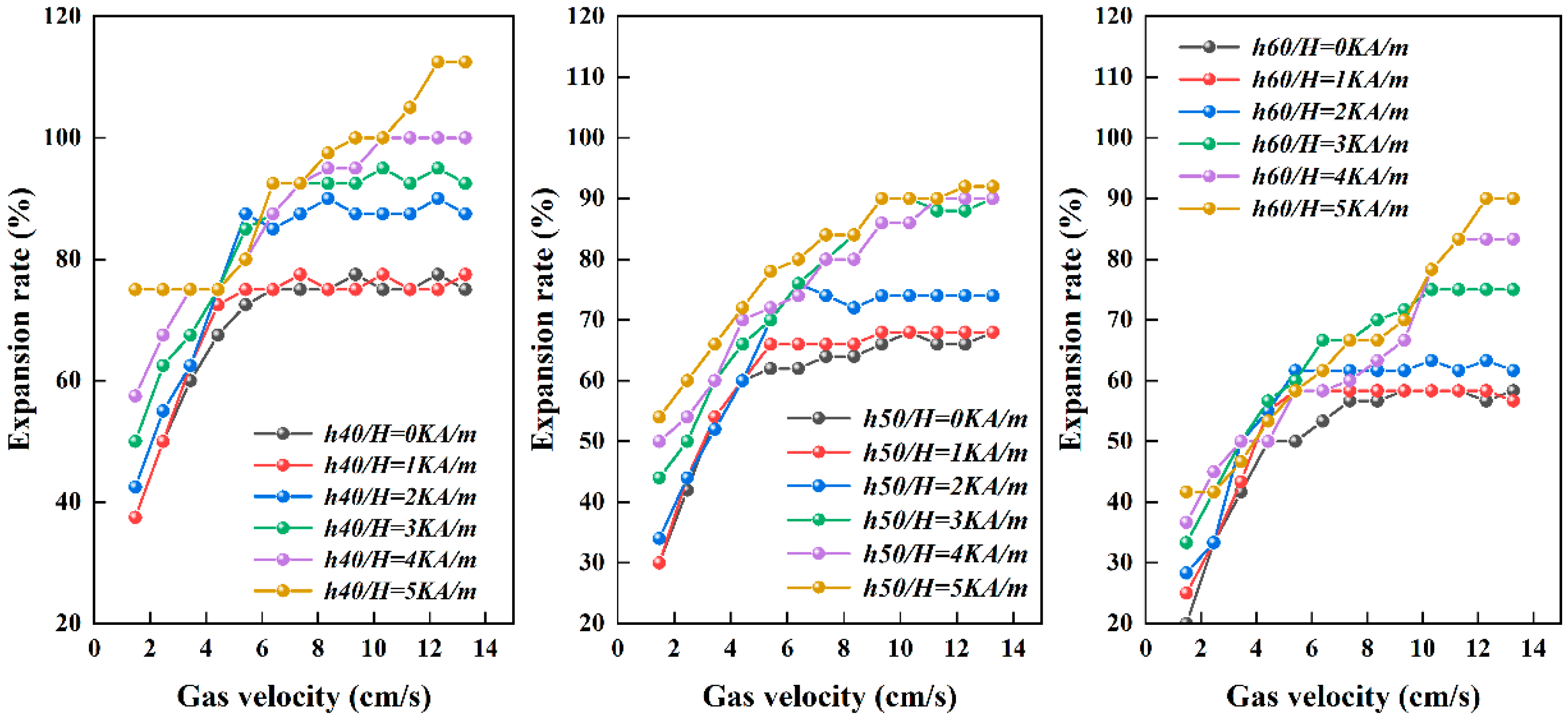
Furthermore, the expansion rate at stable fluidization was investigated, as shown in Figure 10, where the fluidization expansion rate showed an increasing trend with increasing magnetic field strength. As the static bed height increases, the bed fluidization expansion rate decreases. The bed expansion rate can reach up to 112.5% at h0 = 40 mm and H = 5 KA/m.
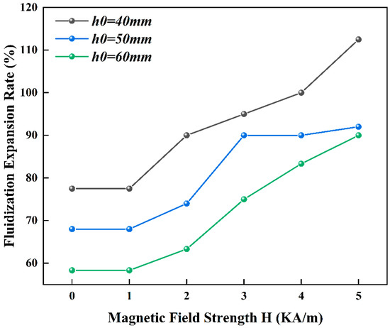
Figure 10.
Stable fluidization expansion rate of the bed under different static bed heights.
The reason for this is that during the stable fluidization phase of the bed, the particles in the bed are in force equilibrium, the presence of a magnetic field generates magnetic chains, the equilibrium of which depends on the combined effect between Fbg (apparent gravity), Fd (drag force), Fv (viscous force between agglomerates) and Fc (collision force between agglomerates). Fv is related to the magnetic field strength and Fc is related to the magnetic field strength and gas velocity [38].
Under the condition of low gas velocity and low magnetic field intensity, the particles are mainly affected by drag force and apparent gravity. According to Equation (6), the increase in static bed height increases the apparent gravity of the bed, decreases the bed expansion rate, and increases the traction force. Therefore, the fluidization expansion rate of a low static bed with high bed height is larger than that of a high static bed with high bed height. With the further increase of magnetic field strength and gas velocity, the agglomerate size increases, and Fv and Fc both increase significantly, while the drag force of airflow on the agglomerate is not significant. The increase of static bed height increases the apparent gravity, which decreases the force of particles in the vertical upward direction and thus reduces the bed expansion rate. Therefore, the bed fluidization expansion rate decreases with the increase of static bed height.
4. Conclusions
(1) The application of the magnetic field changes the fluidization characteristics of microfine particles; when the magnetic field strength increases from 0 KA/m to 5 KA/m, the minimum fluidization gas velocity of particles increases from 4.42 cm/s to 10.32 cm/s;
(2) At the operating gas velocity of fluidization number N = 1, when H < 3.4 KA/m, the overall pressure drop of the bed increases with the increase of magnetic field strength, and the gas flow has a major influence on the fluidization; when H < 3.4 KA/m, with the increase of magnetic field strength, the overall pressure drop of the bed becomes lower, which means that the fluidization is mainly affected by the magnetic field
(3) The sequence of magnetic field addition affects the fluidization state of the microfine particles; the bed undergoes a ‘sudden pressure drop’ when the magnetic field is added later. The time of ‘sudden pressure drop’ decreases with increasing magnetic field strength. In contrast, the ‘adding magnetic field first’ does not experience ‘sudden pressure drop’ and the fluidization state is more stable.
(4) In the stable fluidization stage, when the static bed height is the same, the bed fluidization expansion rate increases with the increase of magnetic field strength; when the magnetic field strength is the same, the bed fluidization expansion rate decreases with the increase of static bed height. The bed fluidization expansion rate of stable fluidization is up to 112.5%.
Author Contributions
Data curation, Y.T.; Methodology, S.S. and Y.T.; Software, Y.T., M.Z. and X.W.; Writing-review and editing, Y.T. and X.X.; Validation, S.S.; Writing—original draft, Y.T. and X.X.; Formal analysis, Y.T., X.X. and S.Y.; Supervision, S.S.; Project administration, S.S. All authors have read and agreed to the published version of the manuscript.
Funding
The research work is financially supported by the National Natural Science Foundation of China (51974306), the funder is Zhenfu Luo. National Natural Science Foundation of China Xinjiang Joint Fund Incubation Project (U2003126), the funder is Bo Zhang. National Natural Science Foundation of China Youth Fund Project (52004282), the funder is Bo Zhang. The Jiangsu Provincial Graduate Research Innovation Program (KYCX21_2431), the funder is Yakun Tian. The Jiangsu Provincial Graduate Research Innovation Program (KYCX21_2407), the funder is Xuan Xu.
Data Availability Statement
Not Applicable.
Acknowledgments
The authors are very grateful to their teachers for their careful guidance in writing the paper and to the other participants for their help.
Conflicts of Interest
The authors declare no conflict of interest.
Abbreviations
| μsHf2x | the magnetic energy possessed by the magnetic chain |
| ρsUg2 | the kinetic energy possessed by the particles |
| μs | the magnetic permeability of the ferromagnetic substance, its value is 1.256 × 10⁻⁶ H/m |
| Hf | the magnetic field strength, A/m |
| x | is the volume fraction of ferromagnetic substance, % |
| ρs | is the density of the ferromagnetic substance, kg/m3 |
| Ug | is the operating gas velocity, m/s |
| N(r) | the total number of primary particles in a spherical domain of radius r |
| D | the fractal dimension |
| a | the radius of the particle, m |
| dc | the length of the magnetic chain, m |
| ρc | the density of the magnetic chain, Kg/m3 |
| ρg | the density of air, Kg/m3 |
| g | the acceleration of gravity, m/s2 |
| μg | the air viscosity coefficient, s/m2 |
Appendix A
In the part of Section 3.1.1 effect of magnetic field strength on bed pressure drop, the bed pressure drop discussed in this paper refers to the overall pressure drop of the bed, and the influencing factors considered are the static bed height and the magnetic field strength of the applied magnetic field; It is a universal rule that the pressure drop increases with the increase of gas velocity in gas-solid fluidized bed, so we do not consider the factor of gas velocity again.
References
- Yang, W.C. Handbook of Fluidization and Fluid-Particle Systems; Siemens Westinghouse Power Corporation: Pittsburgh, PA, USA; Marcel Dekker Inc.: New York City, NY, USA, 2003; Chapter 6; p. 200. [Google Scholar]
- Kunii, D.; Levenspiel, O. Fluidization Engineering, 2nd ed.; Butterworth-Heinemann: Oxford, UK, 1991. [Google Scholar]
- Nowak, W.; Mirek, P. Circulating Fluidized Bed Combustion (CFBC). In Fluidized Bed Technologies for Near-Zero Emission Combustion and Gasification; Scala, F., Ed.; Woodhead Publishing: Cambridge, UK, 2013; Chapter 16; pp. 701–764. [Google Scholar]
- Krzywanski, J.; Czakiert, T.; Shimizu, T.; Majchrzak-Kuceba, I.; Shimazaki, Y.; Zylka, A.; Grabowska, K.; Sosnowski, M. NO x Emissions from Regenerator of Calcium Looping Process. Energy Fuels 2018, 32, 6355–6362. [Google Scholar] [CrossRef]
- Win, K.K.; Nowak, W.; Matsuda, H.; Hasatani, M.; Bis, Z.; Krzywanski, J.; Gajewski, W. Transport Velocity of Coarse Particles in Multi-Solid Fluidized Bed. J. Chem. Eng. Jpn. 2005, 28, 535–540. [Google Scholar] [CrossRef] [Green Version]
- Carter, A.; Briens, L. Inline acoustic monitoring to determine fluidized bed performance during pharmaceutical coating. Int. J. Pharm. 2018, 549, 293–298. [Google Scholar] [CrossRef]
- Zhao, Y.; Li, G.; Luo, Z.; Zhang, B.; Dong, L.; Liang, C.; Duan, C. Industrial Application of a Modularized Dry-Coal-Beneficiation Technique Based on a Novel Air Dense Medium Fluidized Bed. Int. J. Coal Prep. Util. 2017, 37, 44–57. [Google Scholar] [CrossRef]
- Song, S.; Zhang, G.; Luo, Z.; Lv, B.; Cao, X. Comparative analysis of coal beneficiation performance in gas-solid fluidized separation beds with different bed structures. Environ. Eng. Manag. J. 2019, 18, 2343–2353. [Google Scholar] [CrossRef]
- Azimi, E.; Karimipour, S.; Xu, Z.; Szymanski, J.; Gupta, R. Statistical analysis of coal beneficiation performance in a continuous air dense medium fluidized bed separator. Int. J. Coal Prep. Util. 2017, 37, 12–32. [Google Scholar] [CrossRef]
- Oshitani, J.; Kajimoto, S.; Yoshida, M.; Franks, G.V.; Kubo, Y.; Nakatsukasa, S. Continuous float-sink density separation of lump iron ore using a dry sand fluidized bed dense medium. Adv. Powder Technol. 2013, 24, 468–472. [Google Scholar] [CrossRef]
- Chen, C.; Wang, L.; Luo, Z.; Zhao, Y.; Lv, B.; Fu, Y.; Xu, X. The Effect of the Characteristics of the Partition Plate Unit on the Separating Process of 6 mm Fine Coal in the Compound Dry Separator. Minerals 2019, 9, 215. [Google Scholar] [CrossRef] [Green Version]
- Luo, Z.; Zhao, Y.; Chen, Q.; Tao, X.; Fan, M. Effect of Gas Distributor on Performance of Dense Phase High Density Fluidized Bed for Separation. Int. J. Miner. Processing 2004, 74, 337–341. [Google Scholar] [CrossRef]
- Zhou, C.; Dong, L.; Zhao, Y.; Fan, X. Studies on bed density in a gas-vibro fluidized bed for coal cleaning. ACS Omega 2019, 4, 12817–12826. [Google Scholar] [CrossRef] [Green Version]
- Lv, B.; Luo, Z.; Fu, Y.; Zhang, B.; Qin, X.; Zhu, X. Particle mixing behavior of fine coal in density control of gas–solid separation fluidized bed. Particuology 2020, 50, 76–87. [Google Scholar] [CrossRef]
- He, J.; Zhao, Y.; Luo, Z.; Zhao, J.; Duan, C.; He, Y. Improving the separation efficiency of 6-1 mm fine coal by introducing vibration energy to dense medium gas-solid fluidized bed. Physicochem. Probl. Miner. Processing 2015, 51, 95–108. [Google Scholar] [CrossRef]
- Geldart, D. Types of gas fluidization—ScienceDirect. Powder Technol. 1973, 7, 285–292. [Google Scholar] [CrossRef]
- Li, Y.; Zhu, F.; Zhang, Y.; Zhao, Y.; Zhang, G.; Huang, Q.; Dong, L. Characterization of bubble behaviors in a dense phase pulsed gas-solid fluidized bed for dry coal processing. Particuology 2020, 53, 83–91. [Google Scholar] [CrossRef]
- Zhang, Y.; Zhao, Y.; Dong, L.; Duan, C.; Zhou, E.; Lu, J.; Zhang, B.; Yang, X. Flow pattern transition characteristics in vibrated gas-solid fluidized bed of Geldart B magnetite powder using pressure drop signals analysis. Powder Technol. 2018, 327, 358–367. [Google Scholar] [CrossRef]
- Song, S.L.; Zhao, Y.M.; Jia, Z.F.; Tang, L.G.; Yang, X.L. Fine coal particles separation by air-solid magnetic fluidization. J. China Coal Soc. 2012, 37, 1586–1590. [Google Scholar]
- Herrera, C.A.; Levy, E.K.; Ochs, J. Characteristics of acoustic standing waves in fluidized beds. AIChE J. 2002, 48, 503–513. [Google Scholar] [CrossRef]
- Qian, G.H.; Bagyi, I.; Burdick, I.W.; Pfeffer, R.; Shaw, H.; Stevens, J.G. Gas–Solid Fluidization in a Centrifugal Field. AIChE J. 2001, 47, 1022–1034. [Google Scholar] [CrossRef]
- Dong, L.; Zhao, Y.; Cai, L.; Peng, L.; Zhang, B.; Luo, Z.; He, Y. Effect of feed characteristics on the fluidization of separating fluidized bed for dry coal separation. Powder Technol. 2015, 269, 75–84. [Google Scholar] [CrossRef]
- Li, Y.; Zhou, C.; Lv, G.; Ren, Y.; Zhao, Y.; Liu, Q.; Rao, Z.; Dong, L. Prediction of minimum fluidization velocity in pulsed gas-solid fluidized bed. Chem. Eng. J. 2020, 417, 127965. [Google Scholar] [CrossRef]
- Xu, X.; Fu, Y.; Song, S.; Dong, L.; Lv, B.; Chen, Z.; Tian, Y.; Chen, J. Fluidization and separation characteristics of a gas-solid separation fluidized bed in the presence of an acoustic field. Chem. Eng. Res. Des. 2021, 169, 46–53. [Google Scholar] [CrossRef]
- Fan, M.; Chen, Q.; Zhao, Y.; Luo, Z.; Guan, Y.; Li, B. Study on magnetically stabilized fluidized beds for coal separation. Fuel Energy Abstracts 2002, 4, 283. [Google Scholar]
- Rosensweig, R.E. Magnetic Stabilization of the State of Uniform Fluidization. Ind. Eng. Chem. Fundam. 1979, 18, 75–81. [Google Scholar] [CrossRef]
- Penchev, I.P.; Hristov, J.Y. Behaviour of Fluidized Beds of Ferromagnetic Particles in an Axial Magnetic Field. Powder Technol. 1990, 61, 103–118. [Google Scholar] [CrossRef]
- Joaquin, P.E. Dynamic Behavior of Ferromagnetic Particles in a Liquid-Solid Magnetically Assisted Fluidized Bed (MAFB): Theory, Experiment, and CFD-DPM Simulation. Ph.D. Thesis, Oregon State University, Corvallis, OR, USA, 2003; pp. 7–24. [Google Scholar]
- Lu, H.; Wang, S.; Zheng, J.; Dimitri, G.; Ding, J.; Li, X. Numerical simulation of flow behavior of agglomerates in gas―cohesive particles fluidized beds using agglomerates-based approach. Chem. Eng. Sci. 2010, 65, 1462–1473. [Google Scholar] [CrossRef]
- Zhu, Q.; Li, H. Magnetic Fluidization of Group C Powder (I) Mechanism. J. Chem. Ind. Eng. 1996, 47, 54–58. [Google Scholar]
- Song, S.; Zhao, Y.; Luo, Z.; Tang, L. Motion behavior of particles in air–solid magnetically stabilized fluidized beds for separation. Int. J. Min. Sci. Technol. 2012, 22, 725–729. [Google Scholar] [CrossRef]
- Luo, Z.F.; Chen, Q.R. Effect of fine coal accumulation on dense phase fluidized bed performance. Int. J. Miner. Processing 2001, 63, 217–224. [Google Scholar] [CrossRef]
- Yu, K.; Zhong, Z.S. APPLICATION OF FRACTAL DIMENSIONTO CHARACTERIZATION OF ULTRAFINE POWDERS AGGLOMERATION STATE. Chin. J. Mater. Res. 1997, 5, 523–525. [Google Scholar]
- Rhodes, M.J.; Wang, X.S.; Forsyth, A.J.; Gan, K.S.; Phadtajaphan, S. Use of a magnetic fluidized bed in studying Geldart Group B to A transition. Chem. Eng. Sci. 2001, 56, 5429–5436. [Google Scholar] [CrossRef]
- Gros, F.; Baup, S.; Aurousseau, M. Hydrodynamic study of a liquid/solid fluidized bed under transverse electromagnetic field. Powder Technol. 2008, 183, 152–160. [Google Scholar] [CrossRef]
- Zhou, L.; Diao, R.; Zhou, T.; Wang, H.; Kage, H.; Mawatari, Y. Behavior of magnetic Fe3O4 nano-particles in magnetically assisted gas-fluidized beds. Adv. Powder Technol. 2011, 22, 427–432. [Google Scholar] [CrossRef]
- Zhu, Q.; Li, H. Magnetic fluidization of group C powder (II)experimental study. J. Chem. Ind. Eng. 1996, 47, 59–64. [Google Scholar]
- Zhou, T.; Li, H.Z. Estimation of agglomerate size for cohesive particles during fluidization. Powder Technol. 1999, 101, 57–62. [Google Scholar] [CrossRef]


Publisher’s Note: MDPI stays neutral with regard to jurisdictional claims in published maps and institutional affiliations. |
© 2022 by the authors. Licensee MDPI, Basel, Switzerland. This article is an open access article distributed under the terms and conditions of the Creative Commons Attribution (CC BY) license (https://creativecommons.org/licenses/by/4.0/).