Abstract
The removal of chromium-containing impurities, such as chrome spinel (ZCr2O4 where Z = Fe, Mg, Mn) from ilmenite (FeTiO3) concentrates through selective sulphidation, has been investigated by the authors. Laboratory experimental studies using sulphur added to ilmenite concentrates under Becher-type reduction conditions showed it is possible to selectively sulphidise chrome spinels from different ilmenite deposits. In this paper, processes to remove the sulphidised chrome spinels from the bulk ilmenite concentrates were investigated using flotation and magnetic separation techniques. Clustering or fusing of the reduced ilmenite (RI) and sulphidised chrome spinel grains was found to have a detrimental effect on flotation performance and made it difficult to have clear separation. A light wet grind was effective for breaking the clustering, but it caused the sulphide rim to spall off from chrome spinel surfaces, which reduces flotation efficiency. The preliminary results obtained after a magnetic separation (0.7 A) of a demetallised sulphidised RI sample show that the sulphidised chrome spinels preferentially report to the magnetic fraction. Additional magnetic separation of the non-magnetic fraction at a lower current (0.3 A) improved the recovery of sulphidised chrome spinels. The demetallisation process followed by a magnetic separation provided insights into a potential route for the removal of chrome spinels from reduced ilmenite concentrates. These two steps simulate the aeration stage of the Becher process. Further studies are required to optimise the process parameters.
1. Introduction
Ilmenite (FeTiO3) ores are the source of the synthetic rutile (TiO2) used in the production of pigment and titanium metal. There is a strong drive globally to process lower-grade deposits due to a decline in the grade of the primary ores around the world. This includes the processing of lower grade and weathered ilmenite ores where the presence of the associated impurities inhibits the exploitation of some ores. For example, the Murray Basin region in southeastern Australia has numerous coarse-grained (~120–150 µm) strandline ilmenite deposits as well as an extensive, unique type of fine-grained (~50–90 µm), sheet-like deposits, known as WIM-style deposits [1,2,3]. Detrital chrome spinels are contaminant grains within ilmenite ores found in the Murray Basin. An extensive solid solution caused by chemical alteration through weathering modifies the compositional range of the chrome spinels (and the ilmenite), impacting their subsequent separation characteristics. The presence of even minor levels of chromium oxide in the ilmenite concentrate (e.g., >0.05 percent Cr2O3) downgrades the market value of the ilmenite as a potential feedstock for the production of titanium oxide pigment.
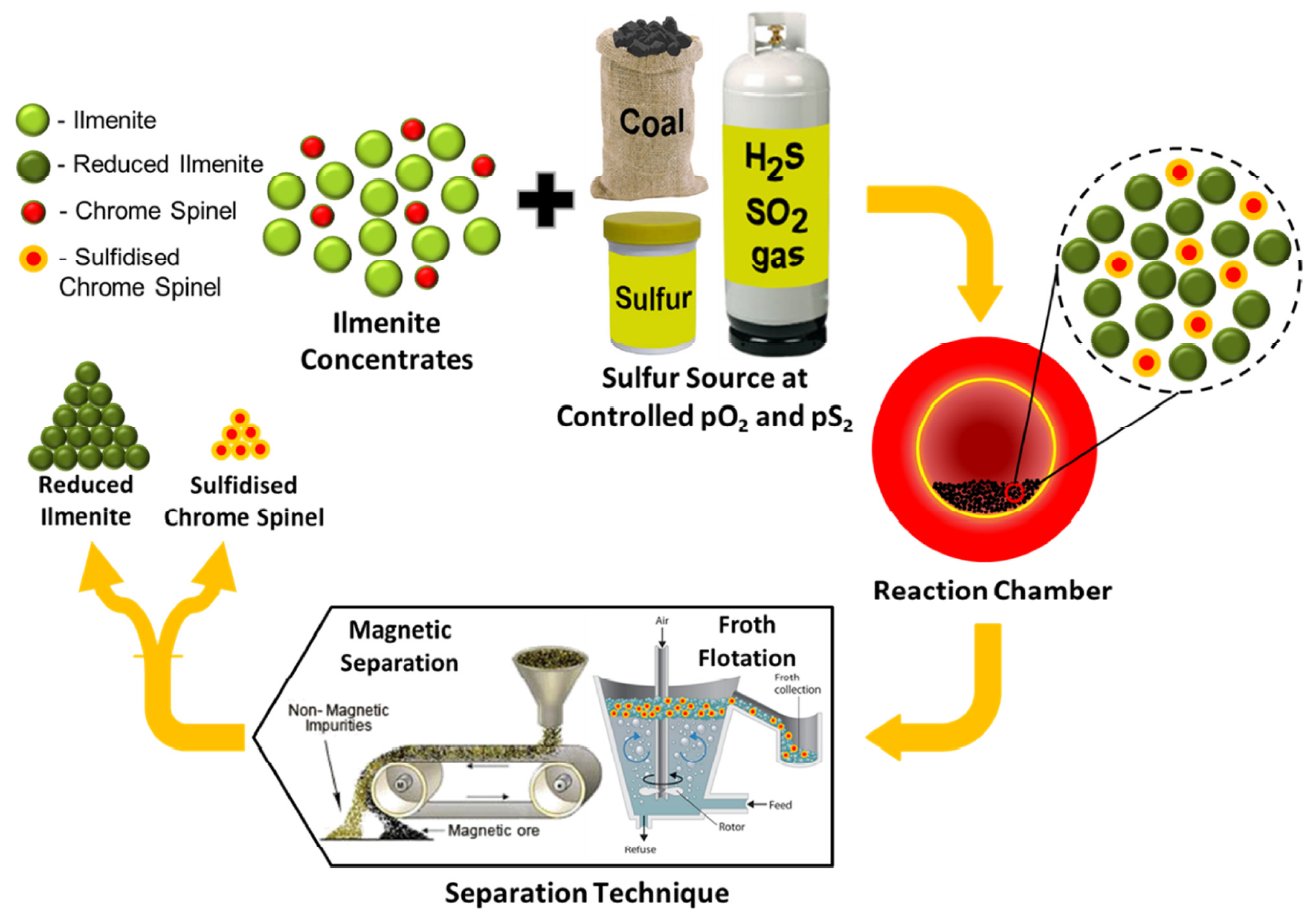
The authors have developed a novel approach for the removal of impurities, particularly chrome spinels, from weathered ilmenite concentrates through selective sulphidation. The approach is explained schematically in Figure 1. In Stage 1, the weathered ilmenite concentrates are subject to high-temperature roasting conditions, which enable the chrome spinel impurities to be selectively sulphidised. This can be achieved by reacting the concentrates with char/coal and sulphur sources (e.g., S, SO2 or H2S). This results in surface sulphidation of the chrome spinel impurities, which forms a sulphide-rich rim and, therefore, induces a change in their surface physicochemical properties. The conditions that promote the selective sulphidation of the chrome spinel impurities were discussed in previous studies by Ahmad et al. [4,5]. The Stage 2 process involves the separation of the sulphidised chrome spinels from the reduced ilmenite.

Figure 1.
Schematic diagram showing the proposed process for chrome spinel impurity removal from contaminated ilmenite concentrates through selective sulphidation. The process is in two parts: Part 1 shows the selective sulphidation of the chrome spinel grains; Part 2: involves the physical separation of the sulphidised chrome spinels from the reduced ilmenite.
In the previous study by Rhamdhani et al. [6], the applicability of Stage 1 selective sulphidation roasting conditions using a static bed laboratory-scale furnace was evaluated for different weathered ilmenite concentrates sourced from different deposit types from the Murray Basin, Australia [7,8,9,10], and Bangka Island, Indonesia. The process was found to be applicable for coarse- and fine-grained chromium oxide-contaminated ilmenites from the Murray Basin, as indicated by the formation of CrS sulphide rims on the chrome spinel grains. However, additional pre-processing of the Bangka Island ilmenite to remove additional sulphur scavenging impurities was identified as being required for successful sulphidation of this ilmenite type. The previous work also demonstrated that selective sulphidation of the ilmenite concentrates using char and sulphur can be performed in a laboratory-scale rotary furnace, which simulates the processing of ilmenite concentrates using the Becher process [11], as practised on a commercial scale in Western Australia [12].
The current study focuses on exploring Stage 2 of the process by examining potential methods for effective separation of the sulphidised chrome spinels from the reduced ilmenite. In the current study, froth flotation was one technique investigated for separating out the sulphidised impurities in a sample (MBI-4) generated from a simulated Becher process (carried out in Rhamdhani et al. [6]). There are very few studies on separating chrome spinel impurities from ilmenite concentrates via flotation. Heyes et al. [13] explained a flotation technique for removing chromite and ilmenite from silicates, but knowledge of ilmenite chrome spinel separation is limited. Smith and Bruckard [14] and Bulatovic [15] also studied froth flotation for removing chrome spinel from ilmenite. They used different mineral sand samples from Australia (Murray Basin) for their studies. Their results indicated that there was a variation in chrome spinel recovery depending on the initial sample composition and the amount of chrome spinel present. The chrome spinels that contain high Al produced the best results during flotation. After flotation, the ilmenite samples from the Murray Basin deposit exhibited a decrease in Cr2O3 concentration by 31.4% to 54.5% depending on the origin and initial composition of the samples.
As well as flotation studies, a magnetic separation was also carried out on the MBI-4 reduced ilmenite (RI) containing the sulphidised chrome spinels after a demetallisation process to remove metallic iron. Since the magnetic separation of the RI was previously demonstrated to be ineffective in separating the sulphidised chrome spinels from the RI due to overlapping magnetic properties, a demetallisation process was performed which simulates the aeration stage of the Becher process in which the metallic iron in the RI is ‘rusted’ into iron oxides and iron oxyhydroxides.
2. Experimental
2.1. Samples and Experimental Plan
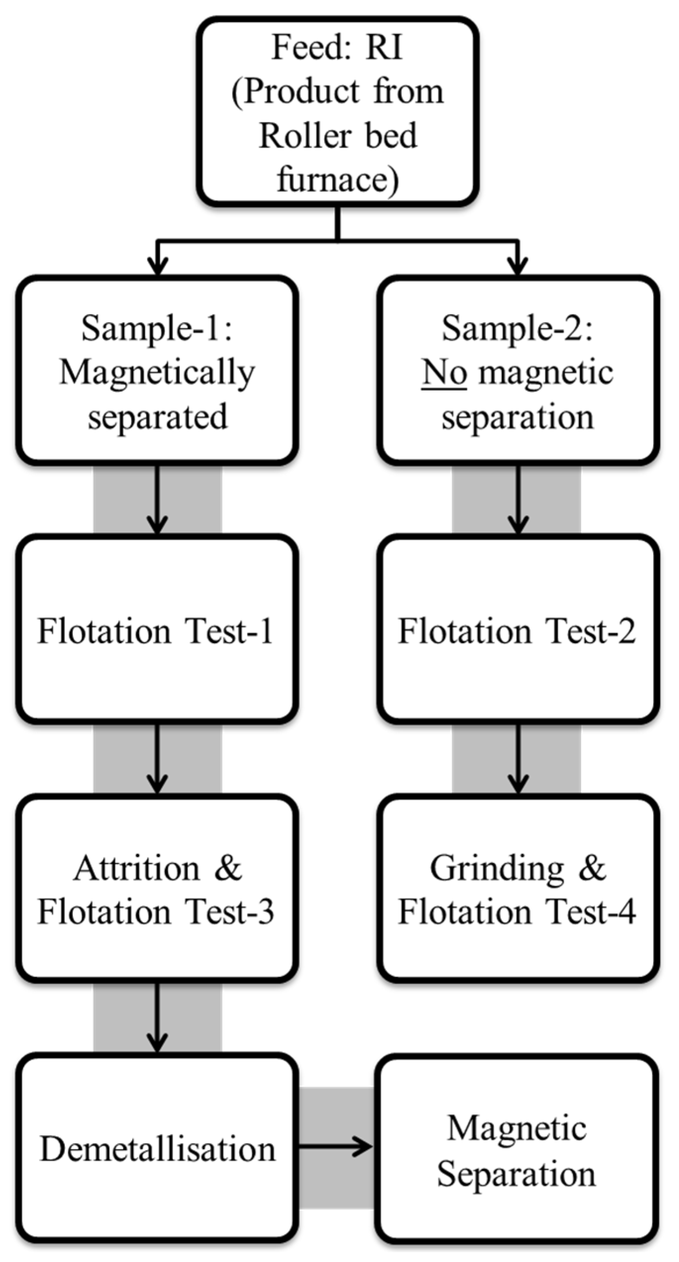
The coarse-grained Murray Basin reduced ilmenite (RI) sample, MBI-4, obtained after sulphidising roasting using sulphur and char in a laboratory roller-bed-furnace, was used in this study. This sample still had a small amount of residual char from the reduction process. To evaluate whether a magnetic separation (to further remove the residual char) was needed before the flotation test, the sample was split into two fractions. A magnetic separation was applied to the first fraction to remove the residual char after preliminary screening (this sample is labelled as Sample-1), while, for the second fraction, no magnetic separation was applied (Sample-2). The rationale for testing these two scenarios was to test the hypothesis that a magnetic separation might not be necessary to apply since any residual char, due to its hydrophobic nature, would likely float along with sulphidised grains during flotation (i.e., report to the flotation concentrate). The sample identification codes for these series of tests are shown in Table 1.

Table 1.
Identification of samples for flotation testing in the current work.
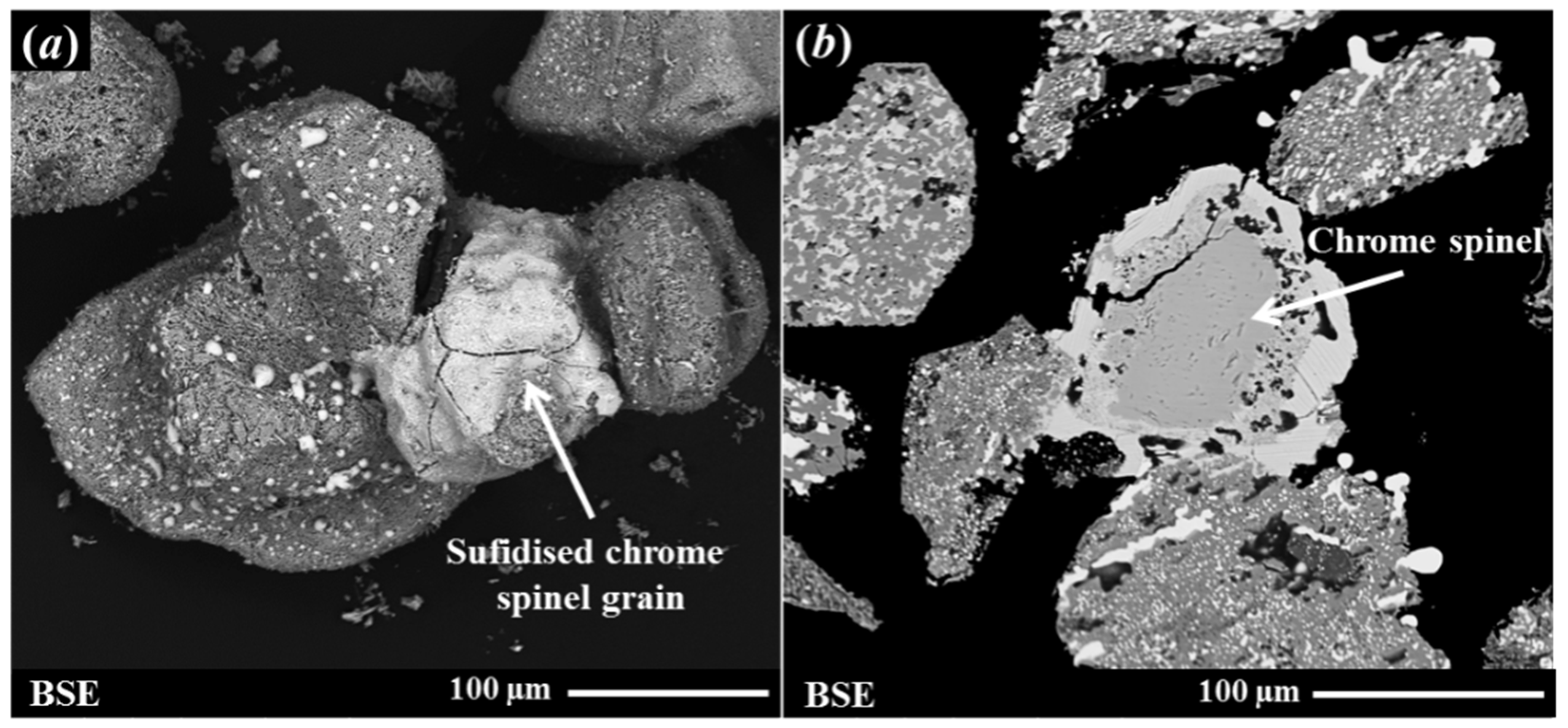
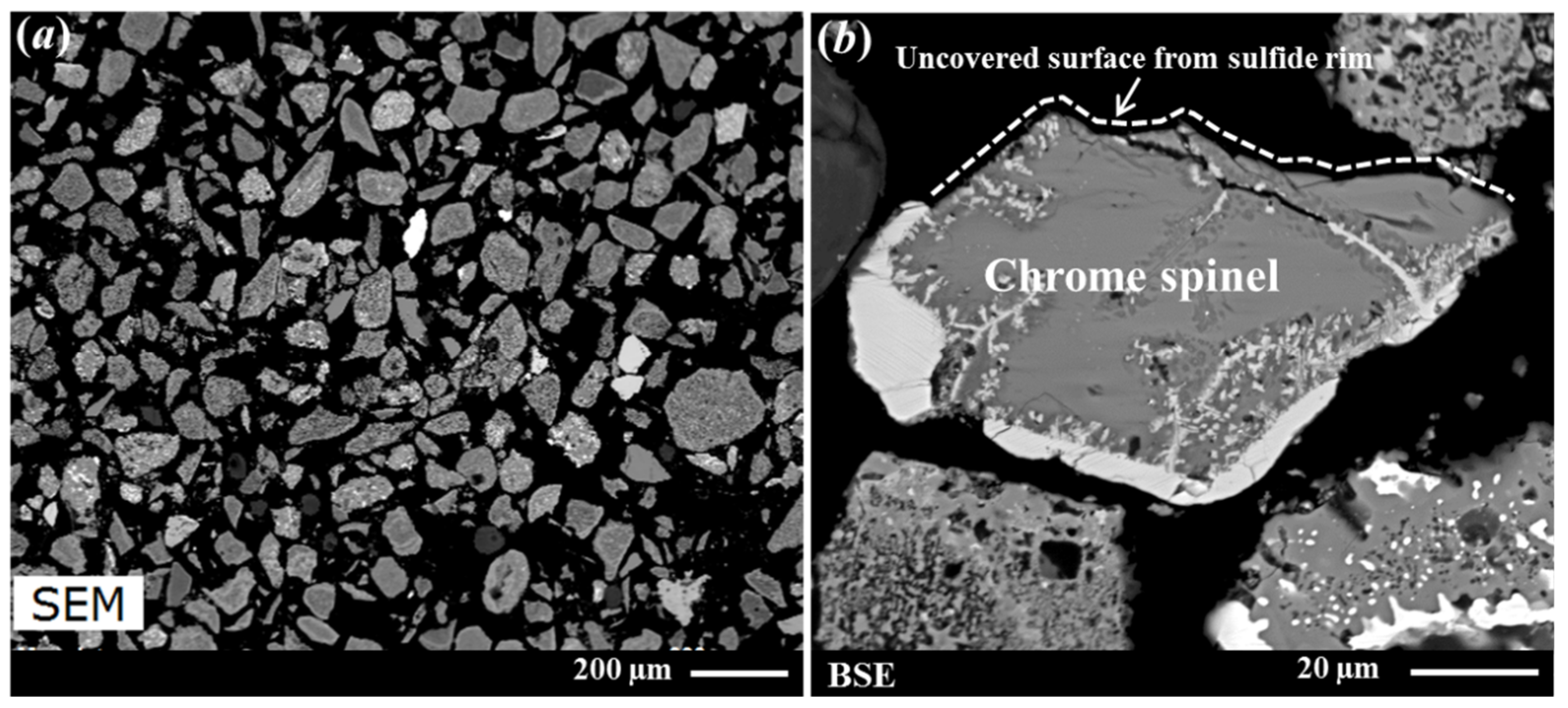
A scanning electron microscopy (SEM, FEI Quanta FEG 400, FEI Company, Hillsboro, OR, USA) analysis was carried out on the MBI-4 RI sample to investigate its microstructure characteristics. It was observed from this analysis that the sulphidised chrome spinel impurities’ grains were clustered and partially fused with the neighbouring RI grains. Figure 2 shows representative SEM images of fused grains of sulphidised chrome spinel and reduced ilmenite grains (surface topography and cross-sectional images). It can be seen from Figure 2 that fusion occurred due to the melting of the sulphide phase, which results in the sticking of the sulphidised chrome spinels to the reduced ilmenite grains. These clusters of grains are typically >100–200 micron in size. It was recognised that this may cause problems in trying to float the sulphidised chrome spinels due to the coarse grain size and relatively high specific gravity. More detailed information on the characterisation results for the chrome spinels and associated sulphidised grains has been presented elsewhere [4,5,6].

Figure 2.
Secondary electron (SE) and back-scattered electron (BSE) images showing clustered grains of reduced ilmenite and sulphidised chrome spinel grains: (a) an SE image showing the surface morphology of sulphidised chrome spine grains; (b) a BSE image showing a sectioned and polished cross-section of particles.
To assess and/or prevent possible negative effects due to the fusion of these grains (as shown in Figure 2) on the effectiveness of flotation, two subsequent tests using two different methods were employed to break up the fused particles to produce finer, more liberated particles, which would hopefully enhance the floatability of the sulphidised grains. These included carrying out: (1) light attritioning in water and (2) light grinding in a rod mill to break up the fused particles. The tail samples obtained from the first two flotation tests on Sample-1 and Sample-2 (i.e., the pulp remaining after flotation) were the feed samples for these two extended flotation tests after the attritioning and grinding processes. These were named Flotation Test-3 and Flotation Test-4, also shown in Table 1.
There was no significant change in the size and shape of the particles in the tail sample after Flotation Test-3; therefore, this sample was used for extended testing. A further demetallisation process followed by a magnetic separation process was carried out on this tail sample from Flotation Test-3. The rationale for this extended test is as follows: It was previously shown [6] that after a magnetic separation, the sulphidised chrome spinels remain with the RI in the magnetic fraction (as these fused grains are attracted to the magnetic field due to the presence of metallic iron after reduction). Flotation Test-3’s tail sample was, therefore, demetallised through leaching using sulphuric acid to remove the metallic iron from the RI so that the fused grains would behave as a non-magnetic material. During the leaching process, the sulphide rim on the chrome spinels remained unaffected. It was reported by Yosida [16] that chromium monosulphide is magnetic at room temperature, and, therefore, the premise was that the demetallised RI (non-magnetic) would be separated from the sulphidised chrome spinels (magnetic) via a magnetic separation process.
The overall experimental plan is shown schematically in Figure 3.

Figure 3.
A schematic of the experimental plan to test the processes for the separation of sulphidised chrome spinels from RI (reduced ilmenite).
2.2. Experimental Procedures
2.2.1. Froth Flotation
As can be seen in Figure 3, four different flotation tests were carried out in this study. The following paragraphs explain the detailed procedures for Flotation Test-1 and Flotation Test-2. The total flotation time was 10 min in each case.
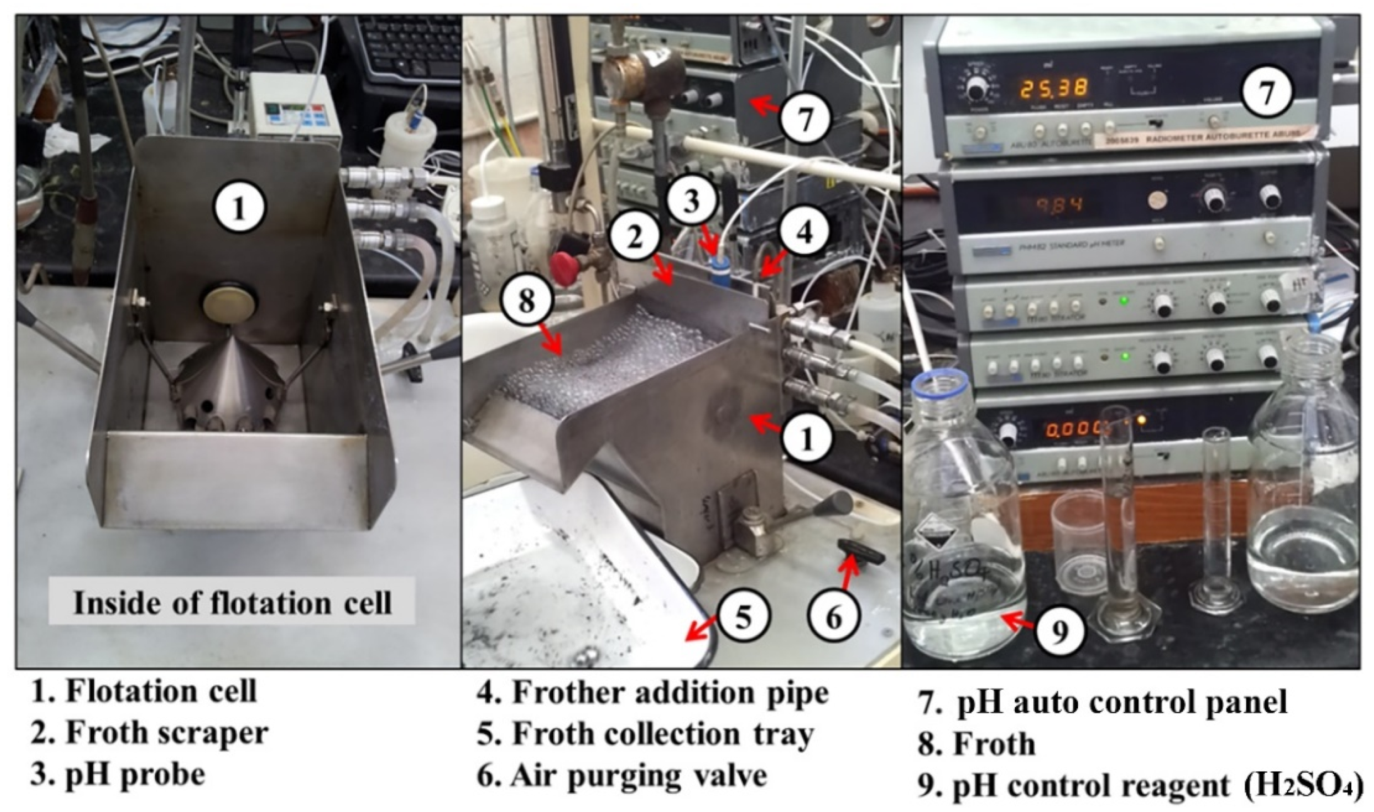
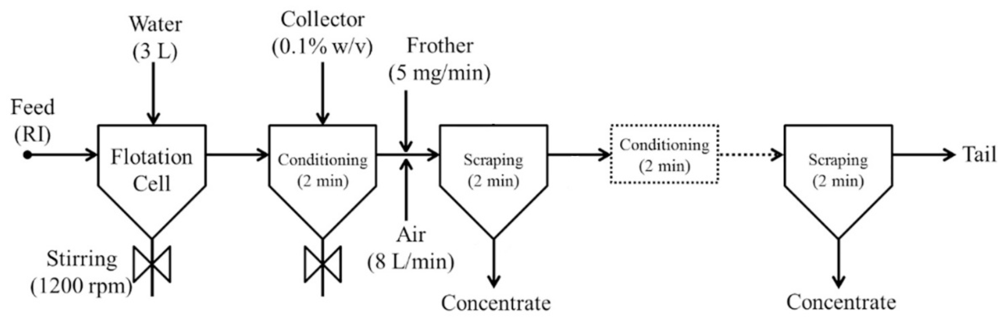
Approximately 300 g of reduced ilmenite (RI) concentrate was floated in a 3 L stainless steel flotation cell (a modified Denver cell, designed and built at CSIRO with key features including bottom driven impeller and pH and pulp level control) using Melbourne tap water. A pulp density of 10 % solid w/v was maintained during the experiments. The pulp was agitated with an impeller at 1200 rpm speed. The flotation reagents used in this study were those typically used to float base metal sulphides [17]. Approximately 0.1% w/v of collector (1% SEX—sodium ethyl xanthate or PAX—potassium amyl xanthate) was added to the flotation cell and allowed 2 min for conditioning. The purpose of conditioning time is to allow sufficient time for the collector to adsorb onto the sulphide mineral surface. Initially, 10 mg of A65 frother (0.25% w/v) was added to the flotation cell, and thereafter it was added at a rate of 5 mg/min during the remainder of the test. Therefore, a total of 50 mL of frother was added during the whole span of the experiment (i.e., 10 min). The initial pH of the slurry varied around 9.8 to 10, and a 2.5% w/v H2SO4 solution was used to set and maintain the pH around 9.0, which is appropriate for sulphide flotation. Figure 4 shows the laboratory flotation cell used in this study.

Figure 4.
Laboratory-scale 3L stainless steel flotation cell used in this study.
After reagent conditioning, synthetic air was introduced into the bottom of the cell at 8 L/min, and timed flotation concentrates were scraped from the cell. Scraping was carried out 2–3 times during the process. In addition, a 2 min frother conditioning time was observed in between two consecutive scraping operations. Notably, at the end of one experiment, a complexing agent, Ethylenediaminetetraacetic acid (EDTA), was added with additional SEX collector, and flotation recommenced. EDTA was tested as the flotation result thus far during the test was poor; one possible reason for this was the formation of unwanted hydroxides on the sulphide surfaces. Complexing agents such as EDTA are useful in these circumstances as they work to solubilise any potential oxidation or hydroxide products that may have developed on the sulphide mineral surface by forming a metal complex. This is a standard diagnostic test used in sulphide mineral flotation. The complete flotation process is shown in Figure 5.

Figure 5.
Schematic of the froth flotation separation process approach used in the study.
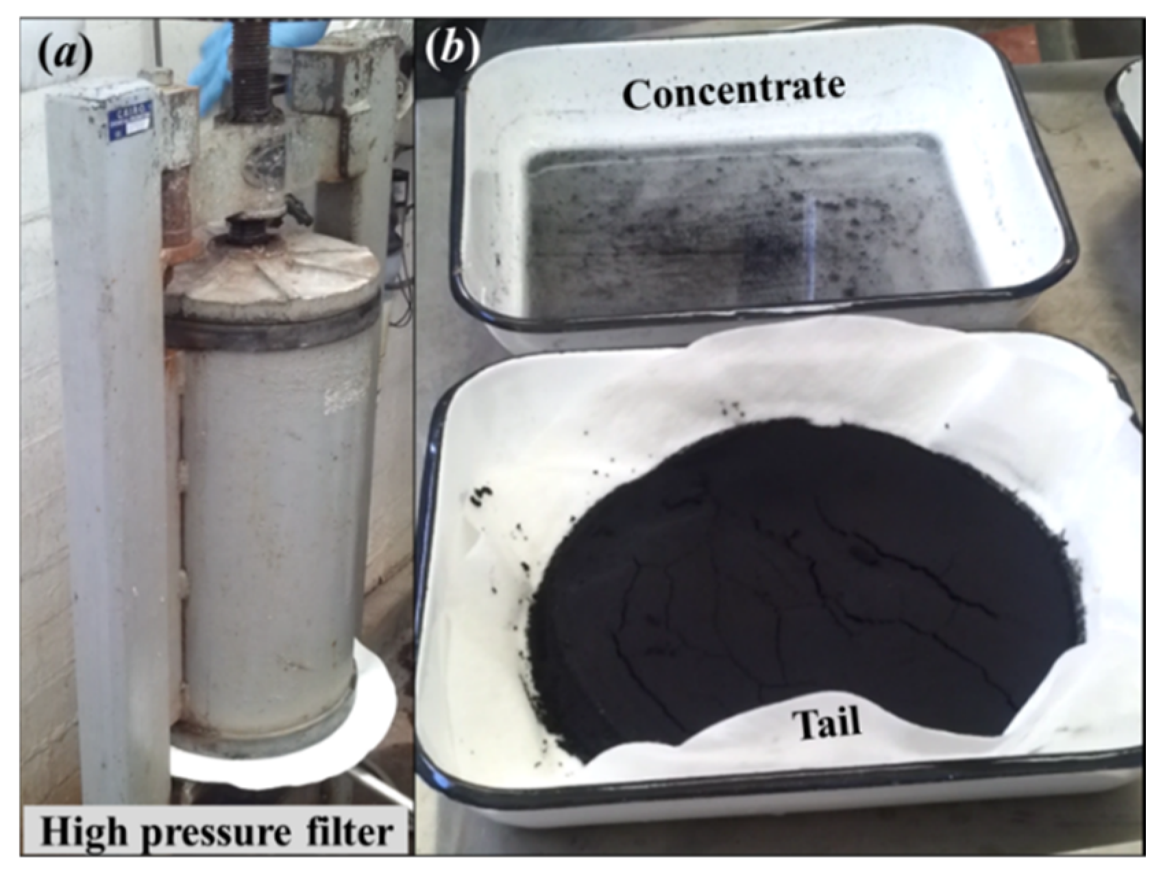
After the flotation test, the tail slurry was de-watered using a pressure filter (standard laboratory 10 L vertical pressure filter). The tail and concentrate samples were dried in an oven (standard laboratory fan forced drying oven) at 60 °C, and the weights were recorded. Figure 6 shows the high-pressure filtration setup and final flotation test products.

Figure 6.
(a) A high-pressure filter used to de-water the tail sample; (b) after filtration tail sample (bottom right) and flotation concentrate (top right).
2.2.2. Attrition and Flotation
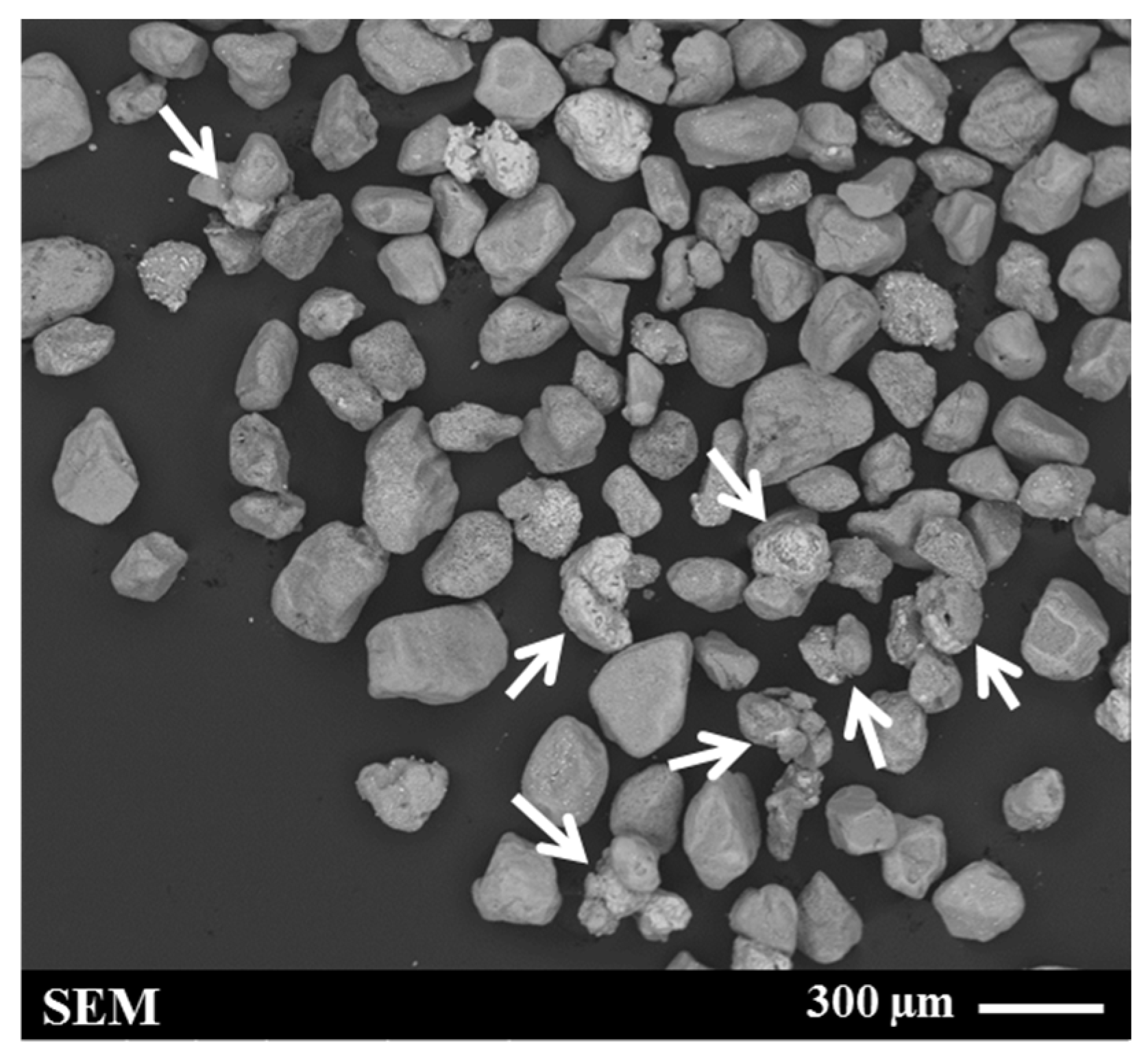
A Denver flotation cell (Denver laboratory flotation machine, made in US, 3 L stainless steel cell) modified to accommodate an attritioning head was used for the attritioning process. Approximately 311 g of RI sample (tail sample after Flotation Test-1) was added to 3 L water and attritioned at a speed of 1200 rpm. The process was carried out for 5 min and repeated (i.e., 10 min total). Each time, the solids were allowed to settle at the bottom of the cell, and the water and fine-grained slimes in the supernatant were removed by decanting. A typical SEM micrograph of the attritioned product is shown in Figure 7. This image reveals that, even after attritioning, clustered grains remained in the sample (indicated by the arrows in Figure 7).

Figure 7.
Secondary electron (SE) image of the sample after attritioning (feed for Flotation Test-3). The sulphidised chrome spinel grains (shown by arrows) typically exhibit a brighter contrast than the RI grains.
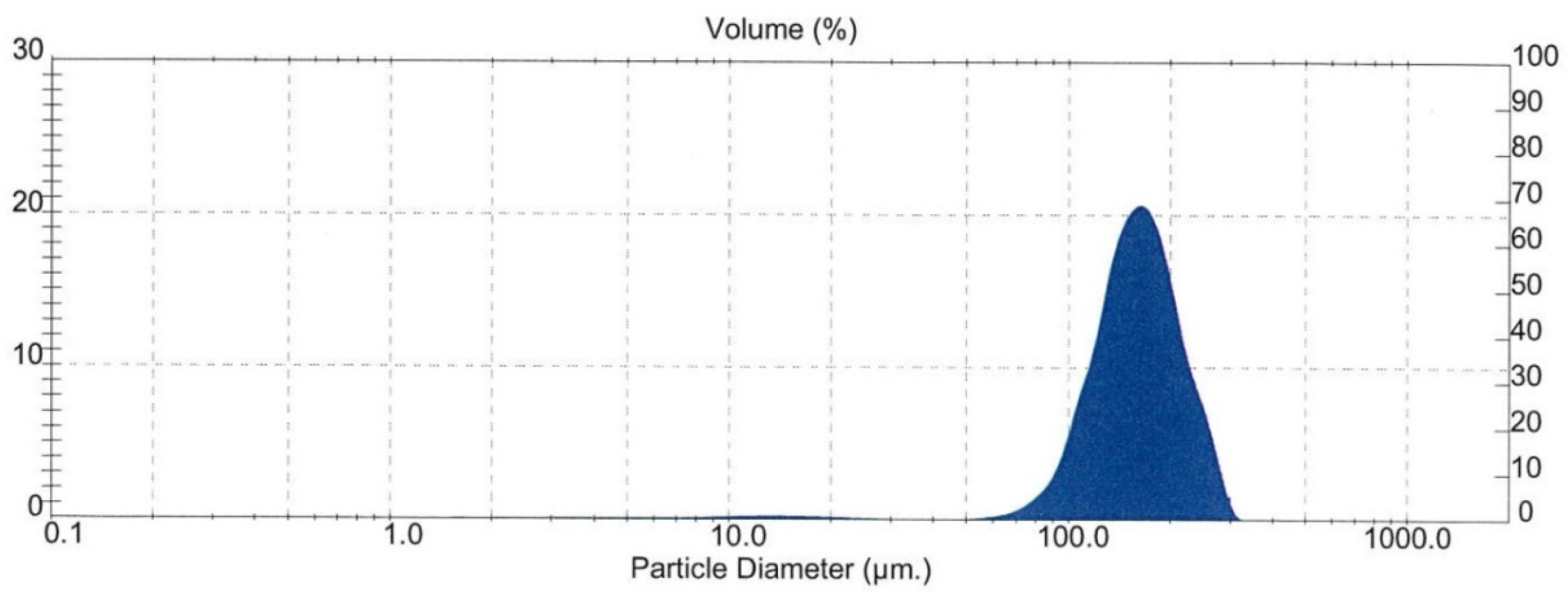
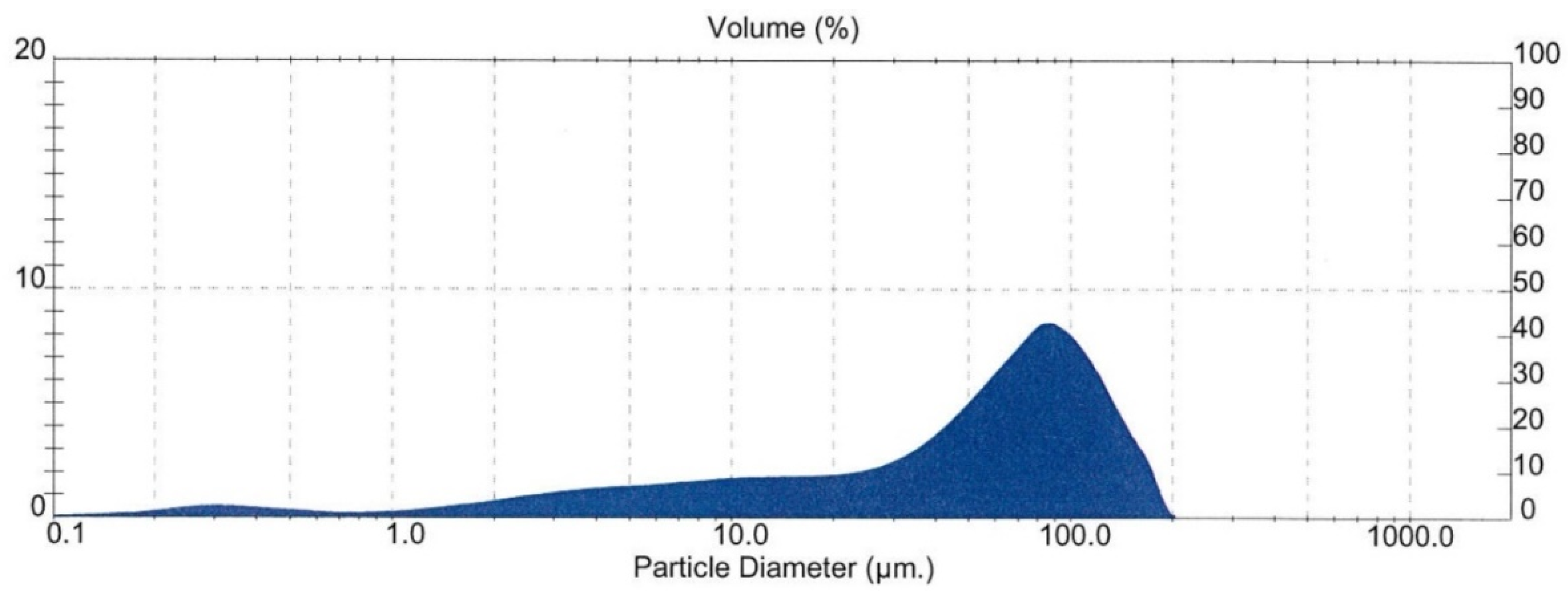
The particle size of the attritioned product was measured by laser sizing analysis (Malvern Mastersizer, Malvern Panalytical, Malvern, UK). The result is shown in Figure 8. It shows that the mean diameter over volume (D43) of the particles was 161 μm, which lies on the higher side of the generally accepted tolerance range (typically ~200 μm upper limit) for general flotation. This may have incurred a negative impact on the flotation.

Figure 8.
Particle size distribution of the sample after attritioning (feed for Flotation Test-3).
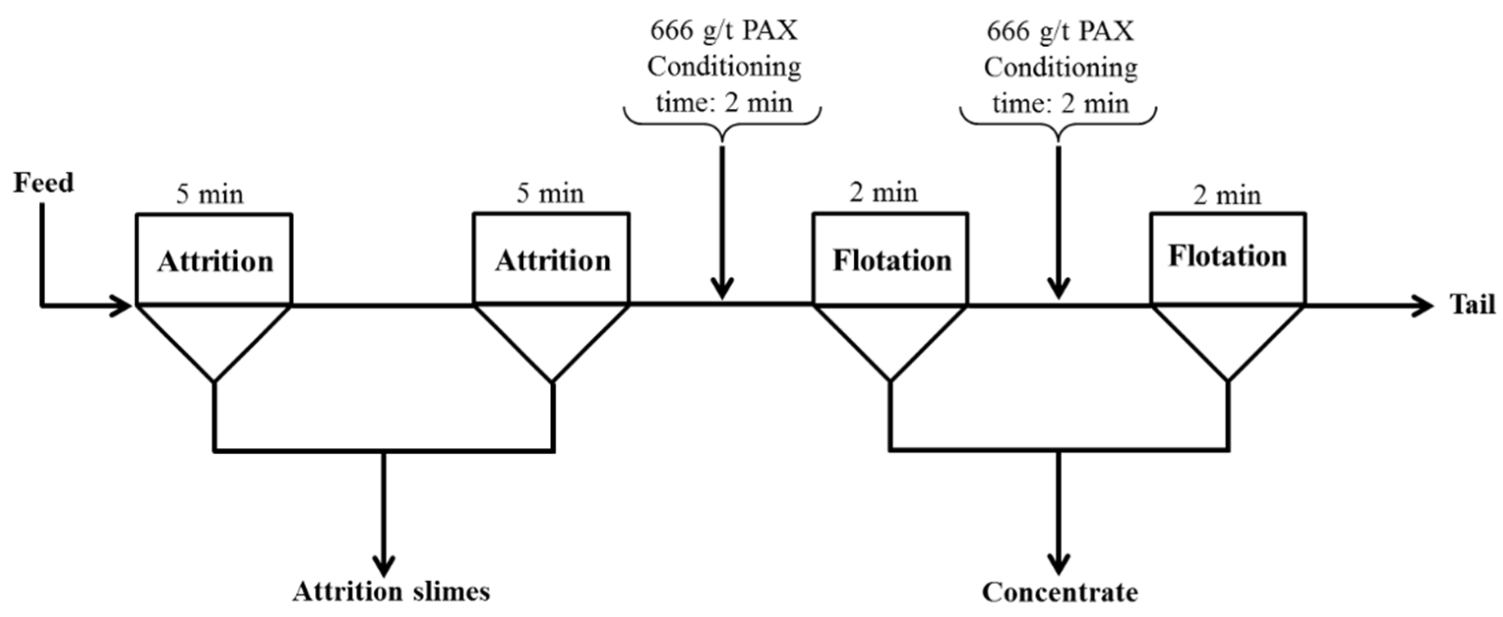
After the attritioning process, the sample (approx. 292 g) was used as the feed for Flotation Test-3 and floated using the flotation test conditions mentioned previously. The collector used in this case was 1% potassium amyl xanthate (PAX). PAX is a stronger collector than SEX due to the longer carbon chain, and it was thought that this might be a more suitable collector for this system. Figure 9 shows the schematic of the attritioning and flotation parameters for Flotation Test-3.

Figure 9.
A schematic flow diagram for attritioning and Flotation Test-3.
2.2.3. Grinding and Flotation
In a second process designed to break up the clustered grains, a wet grinding method was applied to the tail sample from Flotation Test-2. The grinding process involved using a stainless steel rod mill (D = 14 cm; H = 13 cm) and 15 stainless steel rods, which were operated for 10 min. Water was added to give a density of 50% solid during the grinding process. Three water washes of the ground product were carried out to remove the slimes generated. Finally, the sample was dried in an oven at 60 °C and used as feed for Flotation Test-4. The SEM examination of the ground product revealed that both reduced ilmenite and sulphidised chrome spinel grains were reduced in size due to grinding. It was mentioned previously that the sulphide rim is brittle; therefore, it is very likely that some of sulphide rim was spalled from the chrome spinel surface during grinding. This could potentially be detrimental to recovery by flotation. Figure 10a confirms that fused particles were broken down, but it was also observed that there was a substantial size reduction in the grains. While the grinding did remove some of the sulphide rim from the surfaces of the sulphidised chrome spinel grains, Figure 10b shows that, for the most part, the chrome spinel grains retained at least some of the sulphidised rim.

Figure 10.
(a) SEM BSE image of the sulphidised sample after grinding; (b) BSE image of a sulphidised chrome spinel grain after grinding showing a partially removed sulphide rim. This sample is the feed for Flotation Test-4.
Laser sizing analysis of the ground sample confirmed the reduction in the size of the particles with the mean diameter over volume (D43), which was found to be 58.22 μm. The size distribution result for the wet ground sample is shown in Figure 11.

Figure 11.
Particle size distribution results for the wet ground RI sample (feed for Flotation Test-4).
2.2.4. Demetallisation and Magnetic Separation
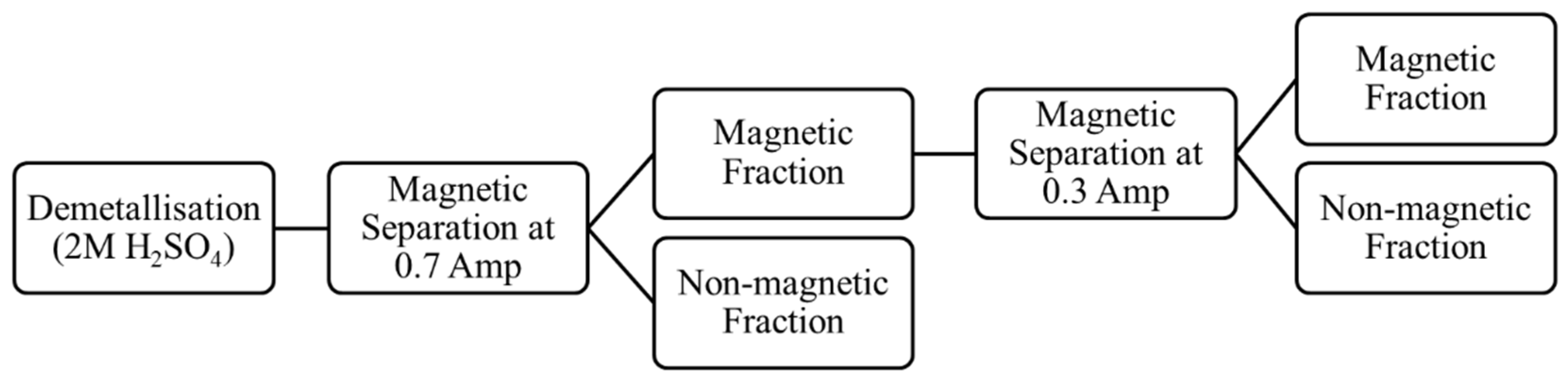
The tail sample (RI) obtained from Flotation Test-3 was used for this study. The metallic iron from the reduced ilmenite was removed using hot-acid leaching. The initial sample was split to obtain a sub-sample of 50 g. The sample was reacted with 500 mL of 2M H2SO4 acid in a round bottom flask fitted with a reflux condenser with stirring at room temperature for 15 min. It was then heated up to 60 °C and further leached for 1 h. After this, the liquor was decanted off, and the solids were washed 5 times in hot de-ionized water, and then dried at 100 °C. The final weight of the product obtained was 32.55 g, i.e., a 34.9% weight loss.
The demetallised sample was then magnetically separated at 0.7 A current. The magnetic fraction obtained after the initial separations was used for an additional magnetic separation at 0.3 A current. The schematic for the demetallisation and magnetic separation process is shown in Figure 12. The details of the samples used in the physical separation studies are listed in Table 2.

Figure 12.
Schematic of the demetallisation and magnetic separation process routes tested (using tail sample from Flotation Test-3).
Table 2.
Identification of samples obtained after the demetallisation and magnetic separation process (using tail sample from Flotation Test-3).
3. Results and Discussion
3.1. Flotation Tests
The samples (concentrate and tail) obtained after each flotation test were dried and weighed. The flotation test results (weight splits) are summarised in Table 3. In all cases, the amount of sample collected in the froth (i.e., concentrate) was very low compared to the tail sample.
Table 3.
Flotation test conditions and results summary.
Table 3 indicates that there was little difference between the results from Flotation Test-1 (magnetic separation applied to further remove char) and Flotation Test-2 (no magnetic separation). It is, however, recommended that char should be removed prior to the flotation test as it can potentially interfere or compete with the collector adsorption and may require higher amounts of the collector than usual (due to consumption of reagent by the char). Table 3 also shows that the amount of concentrate from Flotation Test-1 and Flotation Test-2 were comparatively lower than that from Flotation Test-3 and Flotation Test-4, although the difference was slight.
During the initial stages of Flotation Test-4, it was noted that there appeared to be little or no material floating, and so EDTA was added to the cell, in addition to the SEX collector, to solubilise any potential oxidation or hydroxide products that may have formed on the sulphide mineral surface. However, from Table 3, it can be seen that the EDTA had a minimal effect on the amount of concentrate reported to the froth.
The flotation results indicate that little or no sulphidised spinels were removed during flotation even though the sulphide surface of the spinels would be expected to respond well to flotation under these conditions. X-ray fluorescence (XRF) (BRUKER S8 Tiger WD-XRF, Germany) analyses of the tail samples were carried out to determine their chemical compositions. The results from the XRF analyses are shown in Table 4. For reference, the composition of the initial RI sample is also included in the table. The analyses reveal that there was little variation in the compositions of the tail samples, with the differences assumed to be due to sampling errors. The results confirm that the majority of the chrome spinel grains remained in the tail during the flotation tests.
Table 4.
XRF analyses of feed and tail samples (Tests 1 to 4) after flotation tests (%wt.).
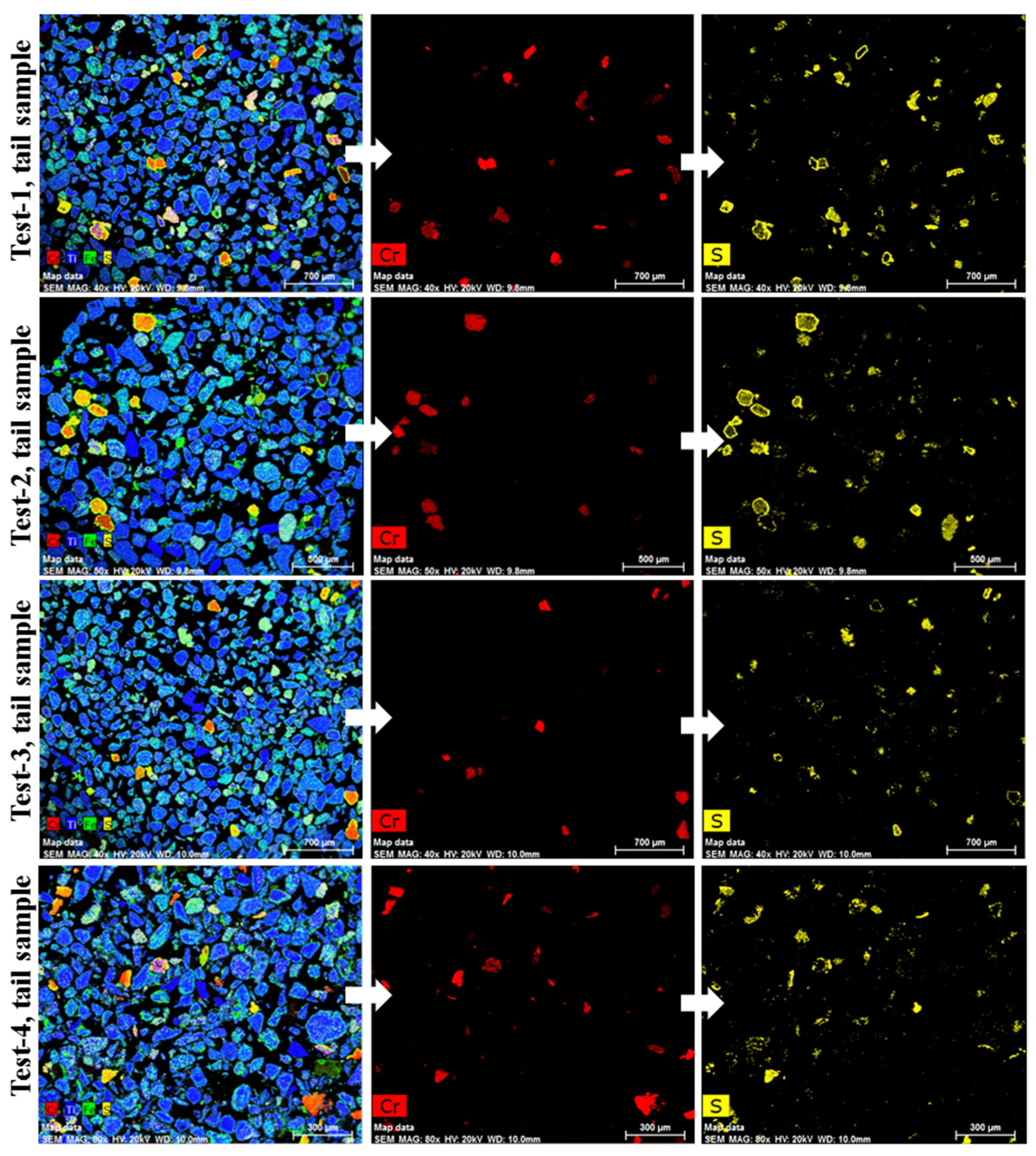
After the flotation test, the tail samples were analysed using Energy Dispersive X-ray (EDX Bruker XFlash® silicon drift detector, Germany) mapping. Figure 13 shows the mapping of the four tail samples obtained. The data confirm the presence of sulphidised chrome spinel grains (red coloured grains) in all the tail samples. The mapping results from Test-3 and Test-4 imply that the attrition and grinding process for breaking up the clustered grains was unsuccessful in increasing the flotation recovery of the sulphidised grains. As shown previously in Figure 7, fused grains remained in the sample even after attritioning. This could be one of the reasons for the non-effective flotation of the sulphidised grains.

Figure 13.
EDX mapping of tail samples obtained after flotation.
Figure 10 also shows that, during the grinding process, both ilmenite and chrome spinel grains were reduced in size, and some sulphide rims were spalled from chrome spinel surfaces. This could potentially reduce the chance of collector attaching to the surfaces of chrome spinel grains. It is also possible that the standard collector trialled in this study, used typically in base metal sulphide flotation systems, may have had poor selectivity for Cr sulphides. Further work is required to assess the selectivity of collectors for this system.
3.2. Demetallisation and Magnetic Separation Tests
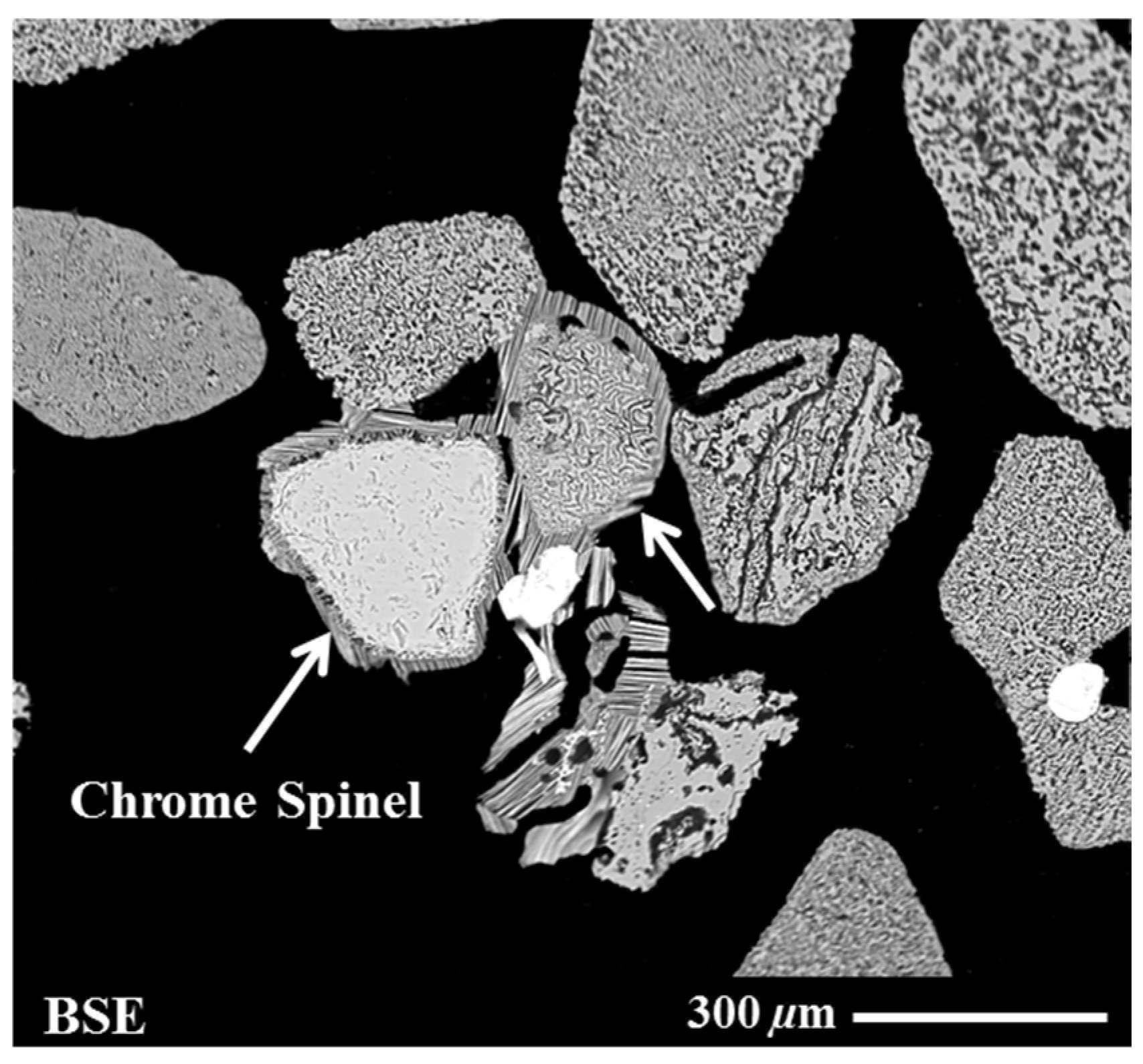
The demetallised and magnetically separated samples were analysed using SEM and XRF techniques. The SEM analysis of the sample after demetallisation is shown in Figure 14. The figure illustrates that the sulphide rim on the chrome spinel grains was unaffected by the demetallisation process. On the other hand, the ilmenite grains became porous due to leaching out of the metallic iron from the reduced ilmenite structure.

Figure 14.
BSE image of the sample after the demetallisation process.
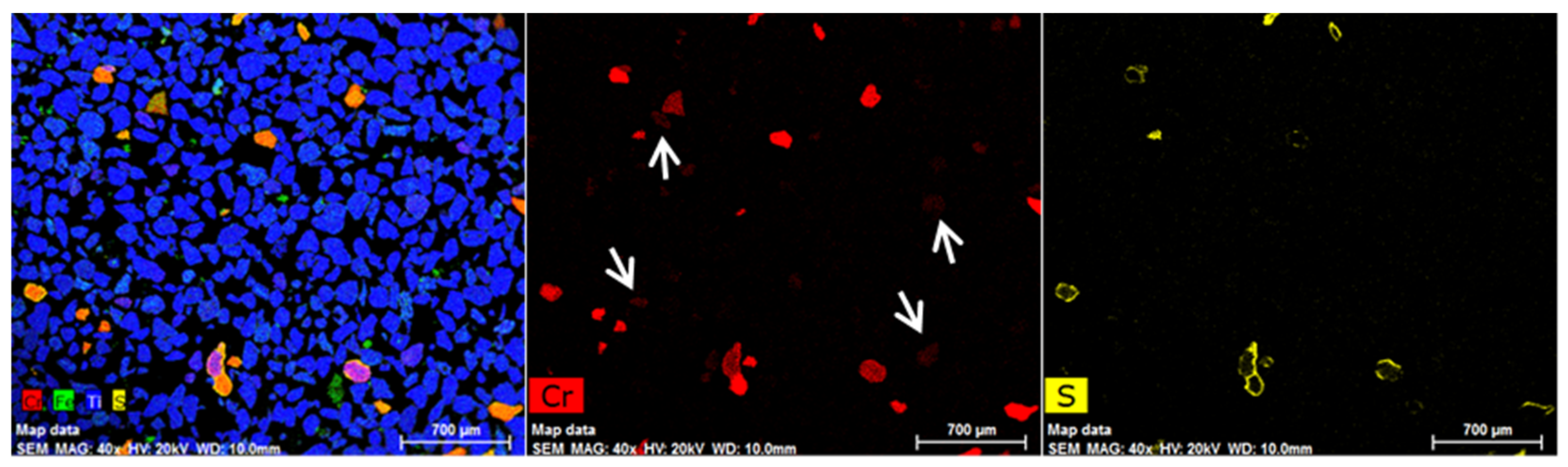
The EDX mapping of the demetallised sample (Figure 15), confirmed the presence of abundant chrome spinel grains with sulphide rims. There were also a few ilmenite grains (indicated by arrows in Figure 15) that contained chromium (2%–4%wt.) but were not sulphidised. Those are probably where the chromium is locked in the fine pores of the reduced ilmenite grains. It was mentioned previously that the weathered ilmenite might contain a considerable amount of chromium (~0.2%wt. Cr2O3) locked in fine pores.

Figure 15.
EDX mapping of sample-DM-1 after the demetallisation with H2SO4.
The XRF analysis of sample DM-1 is shown in Table 5 with the Fe-rich sample prior to demetallisation (tail from Flotation Test-3). The data show that the Fe2O3 content decreased from 33.3 to 3.13%wt. (90.6%), which is consistent with the removal of iron. The amounts of MnO and SO3 also decreased after the demetallisation process, which indicates the dissolution of some manganese as MnS during leaching. The Cr2O3 amounts remained the same, whereas the TiO2 content upgraded from 63.0 to 89.6%wt., which is consistent with weight loss from leaching.
Table 5.
XRF analysis results from sample DM-1 to DM-5 (%wt.). The table also includes the data for the sample before demetallisation (Flotation Test-3 Tail) for comparison.
The demetallised sample DM-1 was magnetically separated at 0.7 A. Table 6 shows the approximate weight split result (magnetic and non-magnetic fraction) after magnetic separation; a total of 76% by weight went to the magnetic fraction. It shows that the non-magnetic fraction contained less sample than the magnetic fraction.
Table 6.
Weight split for sample DM-1 after magnetic separation at 0.7 A.
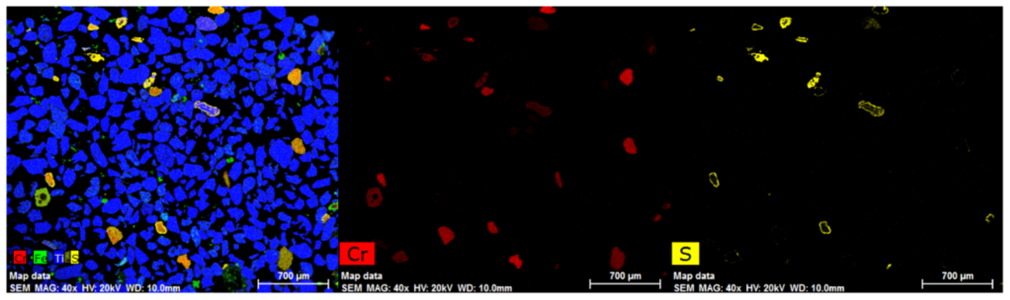
Figure 16 shows the EDX mapping of sample DM-2 (magnetic fraction at 0.7 A). The data indicate that the sample still contained significant numbers of chrome spinel grains with most retaining their sulphide rim. A few chrome spinels were not sulphidised as they were refractory spinel (Mg(Al,Cr)2O4) containing high Al and Mg (i.e., less chromium) contents.

Figure 16.
EDX mapping of sample DM-2 (magnetic fraction) after magnetic separation at 0.7 A.
The XRF analysis of the DM-2 sample is also shown in Table 5. It reveals that the Cr2O3 increased relative to the initial composition, i.e., from 1.67 % Cr2O3 to 1.86% Cr2O3. This suggests that about 85% of the chrome spinel grains deported to the magnetic fraction. The increase in the SO3 content also indicates that the majority of the sulphide product reported to the magnetic fraction.
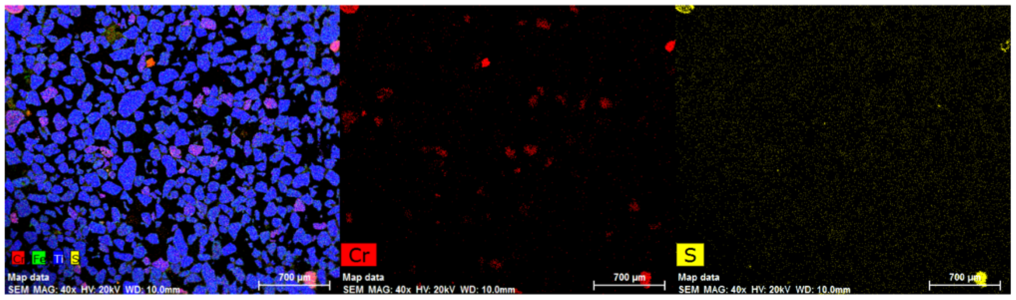
The EDX mapping of DM-3 (non-magnetic fraction at 0.7 A) is shown in Figure 17. The figure illustrates that the number of chrome spinel grains present was low. However, there were a number of reduced ilmenite grains, which contained minor amounts of chromium. The sulphur mapping of DM-3 (right image in Figure 17) confirmed the lack of sulphidised chrome spinel grains in the sample.

Figure 17.
EDX mapping of sample DM-3 (non-magnetic fraction) after magnetic separation at 0.7 A.
The XRF analysis of sample DM-3 is shown in Table 5. It reveals that the Cr2O3 content in the non-magnetic fraction sharply reduced after magnetic separation from 1.67 to 0.55% Cr2O3. This result also confirmed what the EDX mapping results show in Figure 17. The amount of SO3 also decreased from the initial level, which confirms that the majority of sulphide compounds were retained in the magnetic fraction. There was also a slight increase in the TiO2 content of DM-3 and reductions in the Fe2O3 and MnO contents from the initial sample DM-1.
Finally, the DM-2 sample was further processed by a magnetic separation at 0.3 A. The purpose was to make a finer magnetic separation cut and, hopefully, a cleaner non-magnetic fraction (i.e., fewer chrome spinels). Table 7 shows the approximate weight split result (magnetic and non-magnetic fraction) after a magnetic separation at 0.3 A. The result shows that the weight split was nearly equal. Probably, the set current parameter (0.3 A) was higher than the optimum value.
Table 7.
Weight split for sample DM-2 after magnetic separation at 0.3 A.
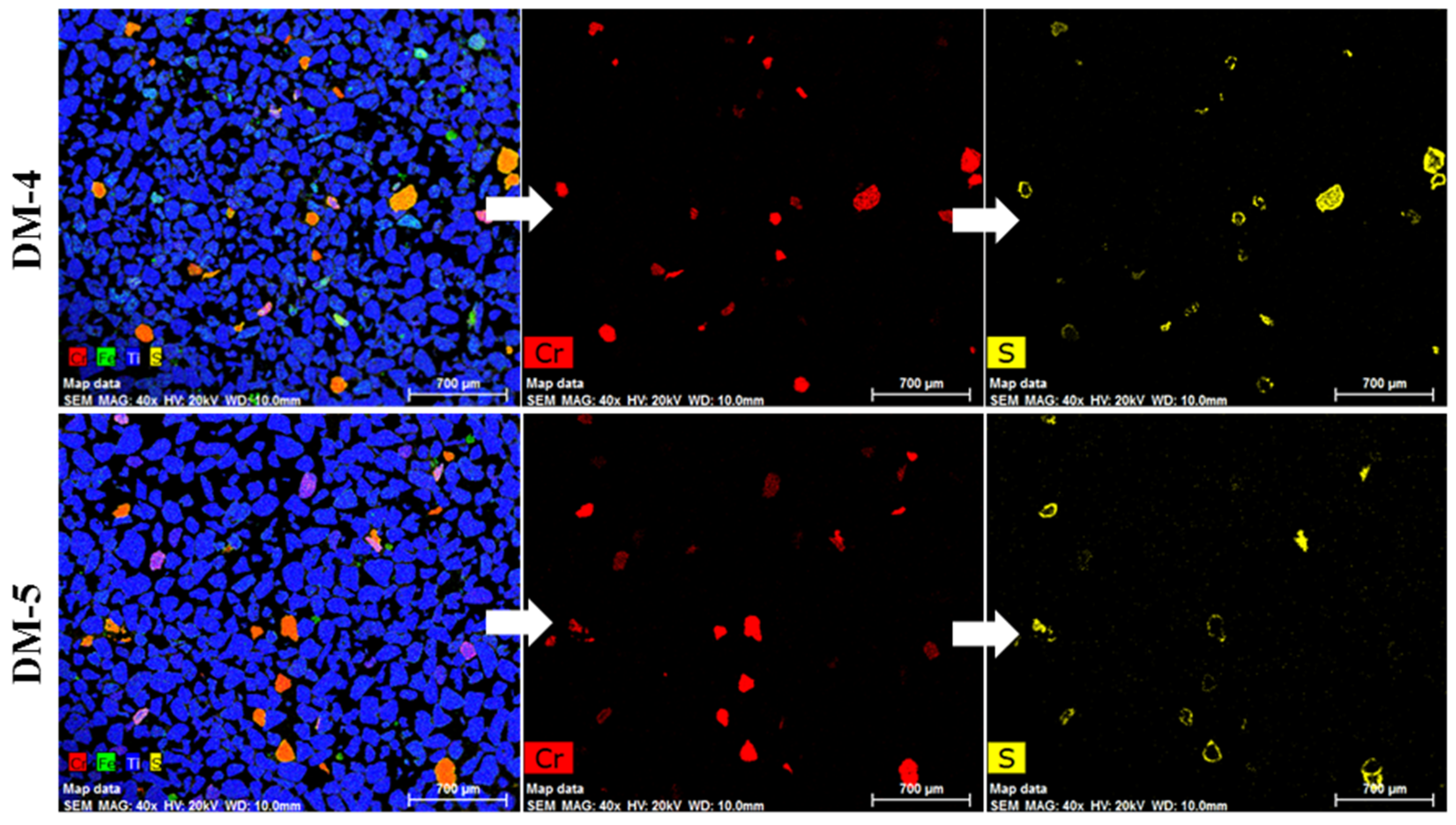
The EDX mapping of the magnetic (DM-4) and non-magnetic (DM-5) fractions are shown in Figure 18. Clearly, DM-5 (non-magnetic) had a considerable amount of chrome spinel compared to the previous non-magnetic fraction, DM-3. This is probably because the current parameter set for the second magnetic separation (i.e., 0.3 A) was higher than the optimum value. Therefore, many more chrome spinel grains reported to the non-magnetic fraction.

Figure 18.
EDX mapping of samples DM-4 (magnetic) and DM-5 (non-magnetic) obtained after magnetic separation of sample DM-2 at 0.3 A.
The XRF analysis results from samples DM-4 and DM-5 are also shown in Table 5. The data reveal that the Cr2O3 and Fe2O3 levels in DM-4 (magnetic fraction at 0.3 A) were both higher than in the initial sample, DM-2. This implies that an additional magnetic separation step or an optimised magnetic separation stage could be helpful for further concentration of the sulphidised chrome spinels. Further work is required to substantiate these preliminary results, but, if successful, this would mean that the optimum time to remove the sulphidised chrome spinels from the RI could be after the aeration stage of the Becher process, in which SR (synthetic rutile) is produced and the Fe is almost completely removed. The results of this study are preliminary, and a full aeration procedure has not been carried out. It is recommended that such a study be conducted.
4. Conclusions
Froth flotation tests were carried out to assess the potential for removing sulphidised chrome spinel grains from ilmenite concentrates. Four different flotation tests were carried out using slightly differently processed feed samples. Flotation Test-1 was carried out using an RI sample, treated to remove residual char by magnetic separation, while Flotation Test-2 used the as-received sample containing residual char after screening, i.e., without magnetic separation. In Flotation Test-3 and Flotation Test-4, the flotation feed sample was attritioned and lightly ground, respectively, prior to the flotation test in order to try to break up the observed fused chrome spinel and ilmenite particles. The following conclusions were drawn from the current study:
- (1)
- The effect of residual char on the feed material during flotation was not apparent in this study. The results of Flotation Test-1 and Flotation Test-2 showed that the concentrates, tail weight splits and compositions were nearly the same in both cases. It is, however, recommended to remove the char from the feed sample prior to flotation to minimise the potential of any unwanted reagent adsorption (loss).
- (2)
- Changing the collector to a stronger xanthate collector (SEX to PAX) had a negligible impact on the chrome spinel recovery.
- (3)
- Clustering or fusing of the reduced ilmenite and sulphidised chrome spinel grains produces a flotation feed containing composite particles, which limits the flotation effectiveness. A simple attrition process was ineffective in breaking up the clustered/fused particles; however, a light wet grind was more effective in breaking the fused grains. The latter process provided a good flotation feed size distribution, but it caused the sulphide rim to spall from chrome spinel surfaces, which also reduces the flotation efficiency. The bulk Cr2O3 level remained unchanged in this test. However, the size reduction led to a slightly more highly concentrated mass pull.
- (4)
- A definitive demonstration of flotation as a process for removing sulphidised chrome spinel was not proven effective under the conditions studied.
- (5)
- The preliminary results obtained after a magnetic separation of a demetallised sample showed that the chrome spinel preferentially reported to the magnetic fraction (at 0.7 A). An additional magnetic separation of the non-magnetic fraction at 0.3 A improved the recovery of sulphidised chrome spinels.
- (6)
- The demetallisation process followed by a magnetic separation provided insight into a potential route for the removal of chrome spinel from reduced ilmenite. However, further studies are required to optimise process parameters, such as the concentration of leachate, leaching time and different current settings for the magnetic separation.
- (7)
- The hot-acid leaching in 2M H2SO4 at 60 °C helped to reduce the Cr2O3 content from 1.67 to 0.55%, increase the TiO2 content up to 91.1% and reach a dissolution of 90.6% Fe2O3.
Author Contributions
Conceptualization, S.A. and M.A.R.; methodology, S.A., M.A.R., M.I.P. and W.J.B.; formal analysis, S.A., M.A.R., M.I.P. and W.J.B.; writing—original draft preparation, S.A. and M.A.R.; writing—review and editing, S.A., M.A.R., M.I.P. and W.J.B.; supervision, M.A.R., M.I.P. and W.J.B.; funding acquisition, M.A.R. and M.I.P. All authors have read and agreed to the published version of the manuscript.
Funding
Swinburne University of Technology-SUPRA Scholarship and CSIRO Mineral Resources Ph.D. Top-Up Scholarship.
Data Availability Statement
Not applicable.
Acknowledgments
The authors would like to acknowledge financial support from Swinburne University of Technology (through a SUPRA Scholarship) and CSIRO Mineral Resources (through a CSIRO Ph.D. Top-Up Scholarship) for this research project.
Conflicts of Interest
The authors declare no conflict of interest.
References
- Whitehouse, J.; Roy, P.S.; Oakes, G.M. Mineral Sands Resource Potential of the Murray Basin; Geological Survey of New South Wales Report GS 1999/038; Geological Survey of NSW: Maitland, NSW, Australia, 1999. [Google Scholar]
- Roy, P.S.; Whitehouse, J.; Cowell, P.J.; Oakes, G.M. Mineral sands occurrences in the Murray Basin, Southeastern Australia. Econ. Geol. 2000, 95, 1107–1128. [Google Scholar] [CrossRef]
- Pownceby, M.I. Alteration and associated impurity element enrichment in detrital ilmenites from the Murray Basin, SE Australia: A product of multistage alteration. Aust. J. Earth Sci. 2010, 57, 243–258. [Google Scholar] [CrossRef]
- Ahmad, S.; Rhamdhani, M.A.; Pownceby, M.I.; Bruckard, W.J. Thermodynamic assessment and experimental study of sulphidation of ilmenite and chromite. Trans. Inst. Min. Metall. 2014, 123, 165–177. [Google Scholar] [CrossRef]
- Ahmad, S.; Rhamdhani, M.A.; Pownceby, M.I.; Bruckard, W.J. Selective Sulphidising Roasting for the Removal of Chrome Spinel Impurities from Weathered Ilmenite Ore. Int. J. Miner. Proc. 2016, 146, 29–37. [Google Scholar] [CrossRef]
- Rhamdhani, M.A.; Ahmad, S.; Pownceby, M.I.; Bruckard, W.J.; Harjanto, S. Selective Sulphidation of Impurities in Weathered Ilmenite. Part 1—Applicability to Different Ilmenite Deposits and Simulated Becher Kiln Conditions. Miner. Eng. 2018, 121, 55–65. [Google Scholar] [CrossRef]
- Pownceby, M.; MacRae, C.M.; Wilson, N.C. Electron microprobe mapping—A diagnostic tool for ilmenite characterisation. In Proceedings of the 3rd International Heavy Minerals Conference, Fremantle, WA, Australia, 18–19 June 2001; pp. 69–74. [Google Scholar]
- Pownceby, M.I.; Fisher-White, M.J. Chemical variability in chrome spinel grains from magnetically fractionated ilmenite concentrates: Implications for processing. Trans. Inst. Min. Metall. 2006, 115, 213–223. [Google Scholar] [CrossRef]
- Bruckard, W.J.; Pownceby, M.I.; Smith, L.K.; Sparrow, G.J. Review and assessment of processing conditions for Murray Basin ilmenite concentrates. Trans. Inst. Min. Metall. 2015, 124, 47–63. [Google Scholar]
- Pownceby, M.I. Compositional and textural variation in detrital chrome-spinels from the Murray Basin, southeastern Australia. Mineral. Mag. 2005, 69, 191–204. [Google Scholar] [CrossRef]
- Becher, R.G.; Canning, R.G.; Goodheart, B.A.; Uusna, S. A new process for upgrading ilmenitic mineral sands. Aust. Inst. Min. Metall. Proc. 1965, 214, 21–44. [Google Scholar]
- Iluka Resources. 2022, Operations. Available online: https://www.iluka.com/operations-resource-development/operations (accessed on 26 August 2022).
- Heyes, G.; Bruckard, W.; Smith, L. Flotation of chromite—A review with applications to upgrading chromium contaminated ilmenite. In Proceedings of the International Heavy Minerals Conference, Fremantle, WA, Australia, 18–19 June 2001; The Australasian Institute of Mining and Metallurgy: Melbourne, VIC, Australia, 2001; pp. 137–142. [Google Scholar]
- Smith, L.K.; Bruckard, W.J. Flotation of Chrome Spinels from Ilmenite—Summary Report. 2002; unpublished data. [Google Scholar]
- Bulatovic, S.M. Handbook of Flotation Reagents, Chemistry, Theory and Practice; Elsevier: Amsterdam, The Netherlands, 2010; Volume 2, pp. 175–207. [Google Scholar]
- Yosida, K. On the magnetic properties of pyrrhotite, chromium sulphide and α-hematite. Physica 1951, 17, 794–796. [Google Scholar] [CrossRef]
- Lee, K.; Archibald, D.; McLean, J.; Reuter, M.A. Flotation of mixed copper oxide and sulphide minerals with xanthate and hydroxamate collectors. Miner. Eng. 2009, 22, 395–401. [Google Scholar] [CrossRef]
Publisher’s Note: MDPI stays neutral with regard to jurisdictional claims in published maps and institutional affiliations. |
© 2022 by the authors. Licensee MDPI, Basel, Switzerland. This article is an open access article distributed under the terms and conditions of the Creative Commons Attribution (CC BY) license (https://creativecommons.org/licenses/by/4.0/).