
Porosity, Mineralogy, Strength, and Reducibility of Sinter Analogues from the Fe2O3 (Fe3O4)-CaO-SiO2 (FCS) Ternary System

 ,
,  ,
,  ,
,  ,
,
Abstract
:1. Introduction
2. Materials and Methods
2.1. Sinter Analogues
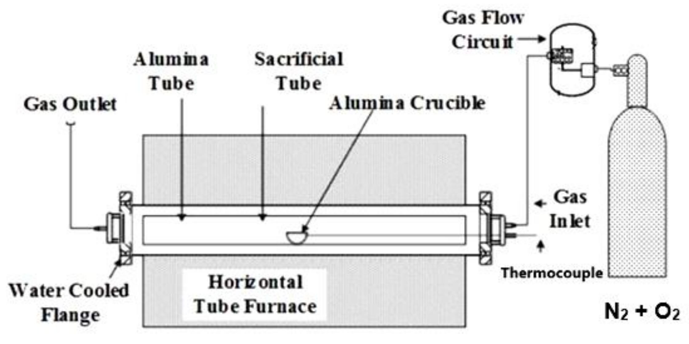
2.2. Apparatus and Sintering Conditions
2.3. Characterisation Techniques
2.4. Strength
2.5. Reducibility
2.6. Porosity
3. Results
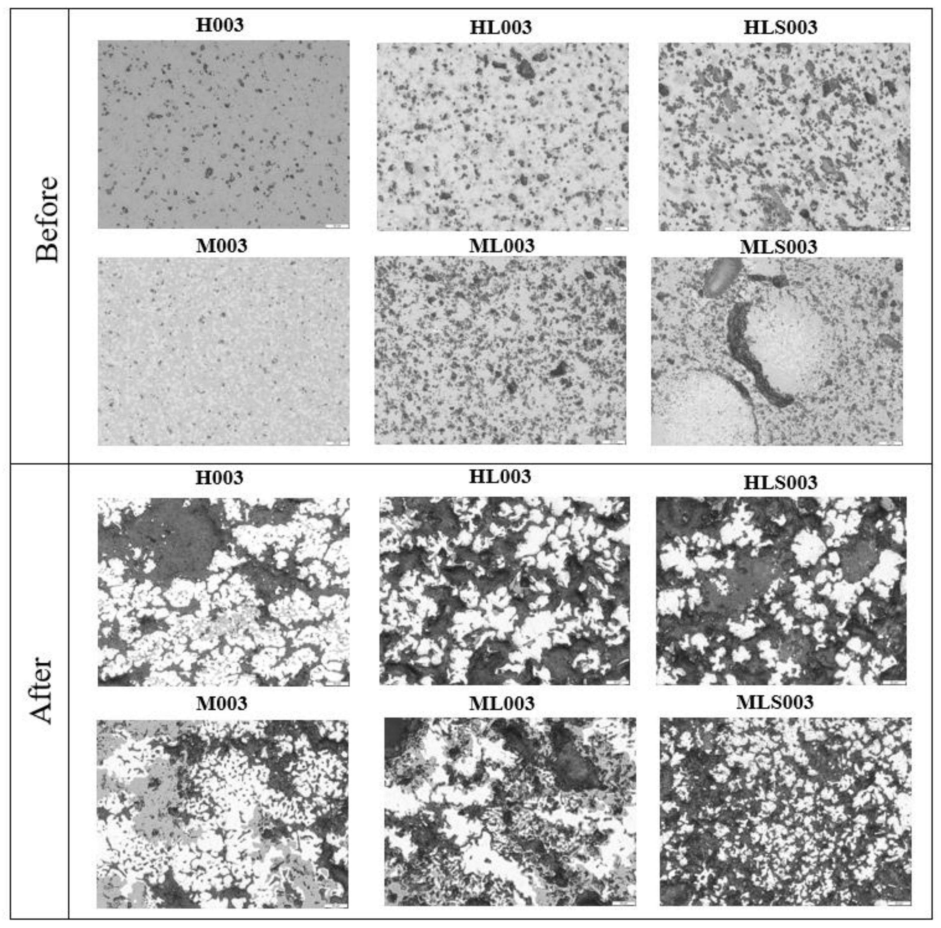
3.1. Mineral Phases and Microstructure in Sinter Analogues
3.2. Effects of Chemistry on Maximum Temperature and Holding Time On
3.2.1. Strength
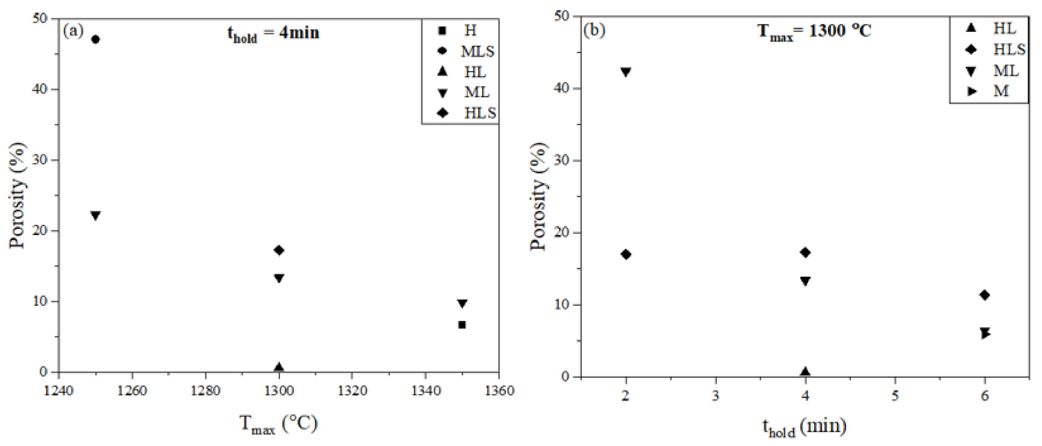
3.2.2. Porosity
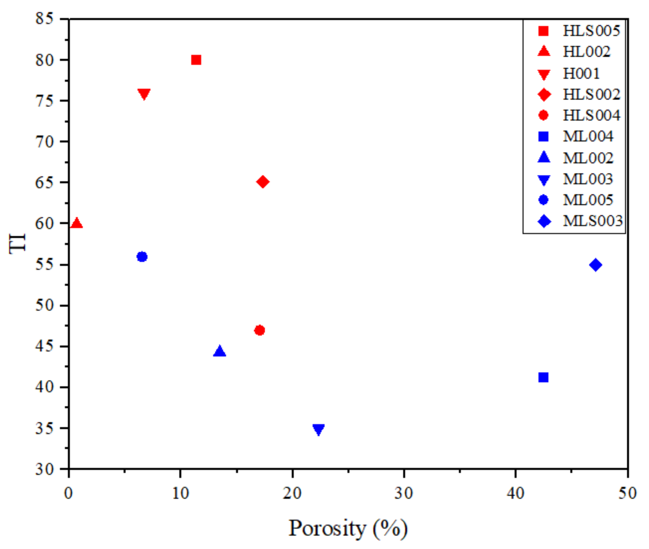
3.3. Reducibility vs. Porosity
3.4. Porosity vs. Strength
4. Conclusions
- (1)
- The formation of calcium ferrites was mostly affected by the sintering conditions rather than the basicity for the hematite-containing samples. The same trend was not observed for the magnetite-containing samples.
- (2)
- The reducibility of the sinter analogues was found to be strongly related to porosity, as expected. The reducibility of the magnetite-containing samples was relatively insensitive to mineralogy.
- (3)
- Most (around 80%) of the sinter analogues samples had similar or higher reducibility than the two industrial sinters (with high contents of SFCA phase) analysed in this study. This is evidence that sinter porosity might play a more relevant role in sinter reducibility than does mineralogy.
- (4)
- Pore formation can be manipulated by changing the sintering conditions (lower Tmax and shorter thold) and chemical composition (adding lime and silica to the samples).
- (5)
- The magnetite-containing samples (MXX003 and MXX004 series) had similar reducibilities to hematite-containing samples (HXX003 and HXX004 series), suggesting that magnetite sinters could be used in the blast furnace.
Author Contributions
Funding
Data Availability Statement
Acknowledgments
Conflicts of Interest
References
- Lu, L.; Ishiyama, O. Iron ore sintering. In Iron Ore: Mineralogy, Processing and Environmental Sustainability; Lu, L., Ed.; Elsevier: Amsterdam, The Netherlands, 2015; pp. 395–433. [Google Scholar]
- Bhagat, R.P. Sintering Fundamentals. In Agglomeration of Iron Ores; CRC Press: Boca Raton, FA, USA, 2019; pp. 117–184. [Google Scholar]
- Biswas, A.K. Raw materials and their properties. In Principle of Blast Furnace Ironmaking, Theory and Practice; Cootha Publishing House: Brisbane, Australia, 1981; pp. 188–261. [Google Scholar]
- Pownceby, M.I.; Clout, J.M.F. Importance of fine ore chemical composition and high temperature phase relations: Applications to iron ore sintering and pelletising. Trans. Inst. Min. Metall. Sect. C Miner. Process. Extr. Metall. 2003, 112, 44–51. [Google Scholar] [CrossRef]
- Harvey, T.; O’Dea, D.; Evans, G.M.; Honeyands, T. Influence of sintering conditions on the reducibility of iron ore sinter analogues. In Proceedings of the Iron Ore Conference, Perth, WA, Australia, 22–24 July 2019; pp. 862–871. [Google Scholar]
- Bristow, N.J.; Waters, A.G. Role of SFCA in promoting high temperature reduction properties of iron ore sinters. Trans. Inst. Min. Metall. Sect. C Miner Process. Extr. Metall. 1991, 100, 1–10. [Google Scholar]
- Harvey, T.; Honeyands, T.; O’Dea, D.; Evans, G. Study of sinter strength and pore structure development using analogue tests. ISIJ Int. 2019, 60, 73–83. [Google Scholar] [CrossRef]
- Shatokha, V.; Korobeynikov, I.; Maire, E.; Grémillard, L.; Adrien, J. Iron ore sinter porosity characterisation with application of 3D X-ray tomography. Ironmak. Steelmak. 2010, 37, 313–319. [Google Scholar] [CrossRef]
- Purohit, S. Alternative Processing Routes for Magnetite Ores. Ph.D. Thesis, Swinburne University of Technology, Melbourne, Australia, 2019. [Google Scholar]
- Pownceby, M.I.; Patrick, T.R.C. Stability of SFC (silico-ferrite of calcium): Solid solution limits, thermal stability and selected phase relationships within the Fe2O3-CaO-SiO2 (FCS) system. Eur. J. Mineral. 2000, 12, 455–468. [Google Scholar] [CrossRef]
- Webster, N.A.S.; Pownceby, M.I. In-situ X-ray diffraction analysis of phase formation during heating of silico-ferrite of calcium (SFC) compositions. ISIJ Int. 2022, 62, 1624–1628. [Google Scholar] [CrossRef]
- Murao, R.; Kimura, M. Investigation on reaction schemes of iron ore sintering process by high temperature in-situ X-ray diffraction and micro-texture observation. Nippon Steel Sumitomo Met. Tech. Rep. 2018, 118, 59–64. [Google Scholar]
- Bhagat, R.P.; Chattoraj, U.S.; Goswami, M.C.; Singh, D.P.; Sil, S.K. Effect of size parameters of mix ingredients on the porosity and reduction characteristics of sinter. Steel Res. Int. 2007, 78, 451–454. [Google Scholar] [CrossRef]
- Hsieh, L.H.; Whiteman, J.A. Effect of oxygen potential on mineral formation in lime-fluxed iron ore sinter. ISIJ Int. 1989, 29, 625–634. [Google Scholar] [CrossRef]
- Harvey, T. Influence of Mineralogy and Pore Structure on the Reducibility and Strength of Iron Ore Sinter. Ph.D. Thesis, University of Newcastle, Newcastle, Australia, 2020. [Google Scholar]
- Clout, J.M.F. Formation of key iron ore sinter phases from Hamersley fines: Implications for ultra fines chemistry and sinter formation. CSIRO 1994, 107–115. [Google Scholar]
- Ware, N.; Manuel, J.R.; Raynlyn, T.; Lu, L. Melting behaviour of hematite and goethite fine ores and its potential impact on sinter quality. In Proceedings of the Iron Ore Conference, Perth, WA, Australia, 12–14 August 2013; pp. 485–486. [Google Scholar]
- Ware, N.; Manuel, J. Fundamental nucleus assimilation behaviour of haematite and goethite containing ores in iron ore sintering. Trans. Inst. Min. Metall. Sect. C Miner. Process. Extr. Metall. 2016, 125, 149–155. [Google Scholar] [CrossRef]
- Clout, J.M.F.; Manuel, J.R. Fundamental investigations of differences in bonding mechanisms in iron ore sinter formed from magnetite concentrates and hematite ores. Powder Technol. 2003, 130, 393–399. [Google Scholar] [CrossRef]
- Pownceby, M.I.; Webster, N.A.S.; Manuel, J.R.; Ware, N. The influence of ore composition on sinter phase mineralogy and strength. Trans. Inst. Min. Metall. Sect. C Miner. Process. Extr. Metall. 2016, 125, 140–148. [Google Scholar] [CrossRef]
- Purohit, S.; Brooks, G.; Rhamdhani, M.A.; Pownceby, M.; Webster, N.A.S. Alternative route for magnetite processing for lower carbon footprint iron-making through lime-magnetite pellets containing CaFe3O5. Ironmak. Steelmak. 2020, 47, 674–685. [Google Scholar] [CrossRef]
- ISO 7215:2015; Iron Ores for Blast Furnace Feedstocks—Determination of the Reducibility by the Final Degree of Reduction Index. International Organization for Standardization: Geneva, Switzerland, 2015.
- Klobes, P.; Munro, R.G. Porosity and Specific Surface Area Measurements for Solid Materials. 2006. Available online: https://tsapps.nist.gov/publication/get_pdf.cfm?pub_id=854263 (accessed on 27 September 2022).
- Espinal, L. Porosity and Its Measurement. Charact. Mater. 2002, 1–10. [Google Scholar] [CrossRef]
- Rouquerol, J.; Avnir, D.; Fairbridge, C.W.; Everett, D.H.; Haynes, J.M.; Pernicone, N.; Ramsay, J.D.F.; Sing, K.S.W.; Unger, K.K. Recommendations for the characterization of porous solids (Technical Report). Pure Appl. Chem. 1994, 66, 1739–1758. [Google Scholar] [CrossRef]
- Pownceby, M.I.; Clout, J.M.F. Phase relations in the Fe-rich part of the system Fe2O3 (– Fe3O4)– CaO – SiO2 at 1240–1300 °C and oxygen partial pressure of 5 × 10⁻³ atm: Implications for iron ore sinter. Miner. Process. Extr. Metall. 2013, 109, 36–48. [Google Scholar] [CrossRef]
- Pownceby, M.I.; Clout, J.M.F.; Fisher-White, M.J. Phase equilibria for the Fe2O3-rich part of the system Fe2O3-CaO-SiO2 in air at 1240–1300 degrees C. Trans. Inst. Min. Metall. Sect. C Miner. Process. Extr. Metall. 1998, 107, 1–10. [Google Scholar]
- Patrick, T.R.C.; Pownceby, M.I. stability of silico-ferrite of calcium and aluminum (SFCA) in air—Solid solution limits between 1240 °C and 1390 °C and phase relationships within the Fe2O3-CaO-Al2O3-SiO2 (FCAS) system. Metall. Mater. Trans. B 2002, 33, 79–89. [Google Scholar] [CrossRef]
- Ding, X.; Guo, X. The formation process of silico-ferrite of calcium (SFC) from binary calcium ferrite. Metall. Mater. Trans. B 2014, 45B, 1221–1231. [Google Scholar] [CrossRef]
- Scarlett, N.V.Y.; Pownceby, M.I.; Madsen, I.C.; Christensen, A.N. Reaction sequences in the formation of silico-ferrites of calcium and aluminum in iron ore sinter. Process Metall. Mater. Process. Sci. 2004, 35, 929–936. [Google Scholar] [CrossRef]
- Karpinskii, O.G.; Arakcheeva, A.V. Crystal structure of ternary hexagonal ferrite phase of Ca3.565 Fe0.06 Fe14.25O25. Sov. Phys. Dokl. 1985, 20, 439. [Google Scholar]
- Arakcheeva, A.V.; Karpinskii, O.G. Crystal structure of hexagonal ferrite, Ca2,95Fe14,85O25. Dokl. Akad. Nauk SSSR 1983, 273, 1127–1129. [Google Scholar]
- Arakcheeva, A.V.; Karpinskii, O.G. Crystal structure of the ternary hexagonal Ca ferrite Ca3.0Fe14.82O25. Sov. Phys. Crystallogr. 1987, 32, 31–32. [Google Scholar]
- Murakami, T.; Wakabayashi, H.; Maruoka, D.; Kasai, E. Effect of hydrogen concentration in reducing gas on the changes in mineral phases during reduction of iron ore sinter. ISIJ Int. 2020, 60, 2678–2685. [Google Scholar] [CrossRef]
- Ignacio, I.R.; Brooks, G.; Pownceby, M.I.; Rhamdhani, M.A.; Rankin, W.J. Porosity in iron ore sintering. In Proceedings of the Iron Steel Technology Conference, Pittsburgh, PA, USA, 16–18 May 2022; pp. 1821–1830. [Google Scholar]
- Hapugoda, S.; Lu, L.; Donskoi, E.; Manuel, J. Mineralogical quantification of iron ore sinter. Miner. Process. Extr. Metall. 2016, 125, 156–164. [Google Scholar] [CrossRef]
- Dehghan-Manshadi, A.; Manuel, J.; Hapugoda, S.; Ware, N. Sintering characteristics of titanium containing iron ores. ISIJ Int. 2014, 54, 2189–2195. [Google Scholar] [CrossRef] [Green Version]
- Pownceby, M.I.; Webster, N.A.S.; Manuel, J.; Ware, N. Iron ore geometallurgy—Examining the influence of ore composition on sinter phase mineralogy and sinter strength. In Proceedings of the Iron Ore Conference, Perth, WA, Australia, 10–11 March 2015; pp. 579–586. [Google Scholar]
- Wright, J.K. The effect of firing conditions on the strength of hematite compacts. Powder Technol. 1976, 14, 103–113. [Google Scholar] [CrossRef]
- Wynnyckyj, J.R.; Fahidy, T.Z. Solid state sintering in the induration of iron ore pellets. Met. Trans. 1974, 5, 991–1000. [Google Scholar] [CrossRef]
- Wright, J.K.; Tyler, R.J. Pore structures of sintered and metallized iron oxide compacts. Powder Technol. 1979, 24, 49–55. [Google Scholar] [CrossRef]


| Tablet ^ | Fe2O3 | Fe3O4 | CaO | SiO2 | Basicity * |
|---|---|---|---|---|---|
| H | 100 | ||||
| M | 100 | ||||
| HL | 95.0 | 5 | |||
| ML | 95.0 | 5 | |||
| HLS | 85 | 10 | 5 | 2.0 | |
| MLS | 85.0 | 10 | 5 | 2.0 |
| Sample No. ^ | Tmax (°C) | thold (min) |
|---|---|---|
| XXX 001 | 1350 | 4 |
| XXX 002 | 1300 | 4 |
| XXX 003 | 1250 | 4 |
| XXX 004 | 1300 | 2 |
| XXX 005 | 1300 | 6 |
| Samples | Crystalline Phase Concentration (Relative wt%) | |||||
|---|---|---|---|---|---|---|
| Hematite | Magnetite | γ-CFF | β-CFF | CaFe2O4 | Ca2SiO4 | |
| H001 | 96 | 4 | ||||
| H002 | 95 | 5 | ||||
| H003 | 95 | 4 | ||||
| H004 | 96 | 4 | ||||
| H005 | 96 | 4 | ||||
| HL001 | 59 | 37 | 3 | |||
| HL002 | 65 | 33 | <1 | 2 | ||
| HL003 | 59 | 18 | <1 | 23 | ||
| HL004 | 80 | 2 | 6 | <1 | 12 | |
| HL005 | 33 | 57 | 10 | |||
| HLS001 | 75 | 9 | 3 | <1 | 11 | |
| HLS002 | 60 | 30 | <1 | 3 | 5 | |
| HLS003 | 66 | 5 | 12 | <1 | 9 | 6 |
| HLS004 | 78 | 1 | 6 | <1 | 8 | 3 |
| HLS005 | 74 | 7 | 6 | <1 | 12 | |
| M001 | 34 | 66 | ||||
| M002 | 41 | 59 | ||||
| M003 | 43 | 53 | ||||
| M004 | 50 | 45 | ||||
| M005 | 32 | 68 | ||||
| ML001 | 7 | 61 | 32 | <1 | ||
| ML002 | 9 | 60 | 31 | <1 | ||
| ML003 | 9 | 60 | 31 | <1 | ||
| ML004 | 12 | 63 | 25 | <1 | ||
| ML005 | 3 | 64 | 33 | <1 | ||
| MLS001 | 11 | 75 | 3 | <1 | 9 | |
| MLS002 | 16 | 67 | 5 | <1 | 9 | |
| MLS003 | 21 | 61 | 6 | <1 | 10 | |
| MLS004 | 15 | 66 | 5 | <1 | 4 | 8 |
| MLS005 | 10 | 77 | 4 | <1 | 8 | |
| Tmax (°C) | thold (min) | Tumble Index | |||||
|---|---|---|---|---|---|---|---|
| H | HL | HLS | M | ML | MLS | ||
| 1350 | 4 | 76 | 74 | 94 | 48 | 39 | 60 |
| 1300 | 4 | 72 | 60 | 65 | 40 | 44 | 56 |
| 1250 | 4 | 62 | 57 | 70 | 32 | 35 | 55 |
| 1300 | 2 | 68 | 56 | 47 | 29 | 41 | 37 |
| 1300 | 6 | 65 | 65 | 80 | 53 | 56 | 67 |
| Samples | Sintering Conditions (Tmax, thold) | Total Porosity (%) |
|---|---|---|
| H001 | 1350 °C, 4 min | 6.72 |
| ML001 | 9.91 | |
| HL002 | 1300 °C, 4 min | 0.66 |
| HLS002 | 17.3 | |
| ML002 | 13.5 | |
| ML003 | 1250 °C, 4 min | 22.3 |
| MLS003 | 47.1 | |
| HLS004 | 1300 °C, 2 min | 17.0 |
| ML004 | 42.4 | |
| HLS005 | 1300 °C, 6 min | 11.4 |
| M005 | 5.98 | |
| ML005 | 6.50 |
| Total Hematite | Total Magnetite | Total SFCA ^ | Others | Porosity (%) | |
|---|---|---|---|---|---|
| IS1 | 26.9 | 16.3 | 40.9 | 15.9 | 9.52 |
| IS2 | 28.4 | 18.0 | 33.5 | 20.1 | 6.10 |
Publisher’s Note: MDPI stays neutral with regard to jurisdictional claims in published maps and institutional affiliations. |
© 2022 by the authors. Licensee MDPI, Basel, Switzerland. This article is an open access article distributed under the terms and conditions of the Creative Commons Attribution (CC BY) license (https://creativecommons.org/licenses/by/4.0/).
Share and Cite
Ignácio, I.R.; Brooks, G.; Pownceby, M.I.; Rhamdhani, M.A.; Rankin, W.J.; Webster, N.A.S. Porosity, Mineralogy, Strength, and Reducibility of Sinter Analogues from the Fe2O3 (Fe3O4)-CaO-SiO2 (FCS) Ternary System. Minerals 2022, 12, 1253. https://doi.org/10.3390/min12101253
Ignácio IR, Brooks G, Pownceby MI, Rhamdhani MA, Rankin WJ, Webster NAS. Porosity, Mineralogy, Strength, and Reducibility of Sinter Analogues from the Fe2O3 (Fe3O4)-CaO-SiO2 (FCS) Ternary System. Minerals. 2022; 12(10):1253. https://doi.org/10.3390/min12101253
Chicago/Turabian StyleIgnácio, Isis R., Geoffrey Brooks, Mark I. Pownceby, M. Akbar Rhamdhani, Willian John Rankin, and Nathan A. S. Webster. 2022. "Porosity, Mineralogy, Strength, and Reducibility of Sinter Analogues from the Fe2O3 (Fe3O4)-CaO-SiO2 (FCS) Ternary System" Minerals 12, no. 10: 1253. https://doi.org/10.3390/min12101253