Article

Lime and Cement Plasters from 20th Century Buildings: Raw Materials and Relations between Mineralogical–Petrographic Characteristics and Chemical–Physical Compatibility with the Limestone Substrate

1
Dipartimento di Scienze Chimiche e Geologiche, University of Cagliari, Cittadella Universitaria di Monserrato, Monserrato, Blocco A, 09042 Cagliari, Italy
2
Dipartimento di Scienze della Terra, dell’Ambiente e delle Risorse, Università di Napoli Federico II, Complesso Universitario Monte Sant’Angelo, Ed. L, Via Cintia 26, 80126 Naples, Italy
*
Author to whom correspondence should be addressed.
Minerals 2022, 12(2), 226; https://doi.org/10.3390/min12020226
Submission received: 24 December 2021 / Revised: 4 February 2022 / Accepted: 6 February 2022 / Published: 10 February 2022
(This article belongs to the Section Clays and Engineered Mineral Materials)

Abstract

:
This paper deals with the “modern” plaster mortars based on air lime, hydraulic lime, and cement used between the 1950s and 1990s of the last century, taking, as a case study, a historical building of the Cagliari city whose foundations and ground floor are cut into in-situ limestone. Different plaster layers (i.e., arriccio and intonachino, paint), applied on the excavated limestone walls, were collected from cave-room. All samples were analysed by optical and electron (SEM-EDS) microscopy and X-ray diffractometry (XRD) in order to define their microstructures, textures and compositional features. In addition, real and bulk density, water and helium open porosity, water absorption kinetic, and saturation index were measured. By microscopic imaging analyses, the binder/aggregate ratio as vol.% was determined. Results revealed that cement mortars, composed mainly of C-S-H, C-A-H, and C-F-H phases, given their high hydraulicity, low open porosity, and a rigid behaviour, showed a good chemical but not physical–mechanical adherence, as they were often found detached from the substrate and frequently loaded with salt efflorescence. On the contrary, the hydraulic lime-based mortars, characterised by a binder composed of C-S-H and C-A-H phases and calcite derived from the portlandite carbonation, showed a greater affinity with limestone substrate and other plasters. Thus, they are more suitable to be used as a repair mortar, showing a long durability on the time. The thin air lime-based plasters (intonachino) showed a good adhesion to the substrate, exerting their coating function better than the harder, cement-based mortars. Lime-based wall paints have a good chemical adhesion and adaptability to the irregular surface of the substrate, due to low thickness of lime paint layers (<1 mm) that confers an elastic physical behaviour.

1. Introduction

1.1. State of Art and Aims of Research

The use of mortars has been well documented since ancient times. Mud and clay were likely the first binders, given not only their wide availability but also the low technology required for their application [1,2]. Lime-based mortars have been used since at least 6000 B.C. as testified by several archaeological sites, among others, in Israel, Syria [3], and Turkey [4]. During the later centuries, air lime mortars were adopted by several civilizations, such as the Egyptians, Minoans, Greeks, Romans, etc. The raw materials, the calcination technologies and the building techniques evolved in different ways from one locality to another, leading each place to obtain its own style and best practices [2]. A plethora of papers deals with historical mortars, stones, and other geomaterials, with all of their related aspects, including archaeological inferences and significance [5,6,7,8,9,10,11,12,13,14], raw materials provenance [15,16,17,18,19,20,21,22,23,24], the chemical, mineralogical and physical properties [25,26,27,28,29,30,31,32], degradation issues [33,34,35,36,37,38], and conservation/restoration techniques [39,40,41,42,43,44,45].
Recent and presently used mortars are extensively studied as well, in order to characterise newly discovered materials, to revise/improve old techniques, and to evaluate the performances of different mortars under different application conditions. Investigations of new mortars can have several aims, from finding eco-sustainable building techniques, to testing highly performing novel materials, as well as from applications in new constructions to their use in repairing/restoring buildings belonging to cultural heritage. Regarding the last point, a great attention is paid to the use of materials such as, among others, nanolimes, hydraulic limes, and aerial limes, mixed with natural or synthetic additives.
If, on one hand, both historic and recent mortars are well described and characterised, on the other hand, the use in the same building of various kinds of air lime, hydraulic limes, and cement-based mortars belonging to the recent past are less studied. Generally, the works mainly deal with the degradation, e.g., [46,47] and production technology of air/hydraulic limes and cement-based mortars, e.g., [48,49,50]. In recent times, researchers have shown attention and interest in the natural hydraulic lime used as an environmentally friendly binder for mortar production and its role as a replacement for many traditional materials, especially in relation to modern cement materials [51,52,53,54,55,56]. However, there is no specific literature on the overlapping and reciprocal compatibility of paints, air lime, hydraulic lime, and cement mortar layers, especially when they have been laid in place over decades and in a complex wall stratigraphy. It is our opinion that it would be considerably interesting to understand and characterise the long-term effects of aging and to investigate the deterioration processes before they become too pervasive and irreparable. The study of the interaction between a mortar and its substrate after a period lasting decades can help to predict the long-term effectiveness of repair mortars applied in historical monuments. Furthermore, the study of recent mortars would be very useful in understanding the overlapping and compatibility of several layers of mortar during the restructuring interventions that have been repeated over the decades and recent centuries. This frequently happens in civil buildings, within the historic centres of important cities that have significant architecture.
In the here-presented case study, we analysed the mortars used for plastering the inner walls of a historical building (XVIII cent.) of Cagliari centre (Sardinia, Italy), located nearby medieval fortifications (XV-XVII cent.). The sampled mortars belong to the underground space of a building carved into the limestone rock (Figure 1), made in a timeframe spanning from the 1960s to the 1990s of the past century. This site offers the opportunity to study various kinds of mortars that differ in binders (cement, feebly hydraulic lime, and air lime), binder/aggregate ratios, and aggregate grain-size, but that were exposed to the same environmental conditions (climate, temperature, moisture contents, etc.) and were applied on the same substrate. Another significant implication of this study arises from the fact that the mortar substrate belongs to the Calcari di Cagliari Fm, a limestone formation extensively used to build up several monuments in the Cagliari and surrounding areas; the understanding of how a mortar behaves ten years after its application could help to choose the most suitable material to be used in future repair interventions on monuments built using similar rocks.
Several mortar samples were collected from different points of the patchy-plastered walls. The sample set included plasters of different compositions (air lime-, hydraulic lime-, and cement-based) and with different functions, i.e., arriccio coat (from the traditional Italian plastering) and finishing coats (hereafter intonachino, paint). The following features have been studied and determined: (i) mineralogical and petrographic characteristics of the aggregate and C-S-H and C-A-H phases present in the binder, through optical polarised light microscopy and XRD analysis; (ii) physical (density, porosity, water absorption) and mechanical properties by H2O- and He-picnometry; (iii) the relationships between compositional and physical–mechanical characteristics; (iv) the differences in physical–mechanical behaviour between air lime-, hydraulic lime- and cement-based mortars; (v) compatibility of the materials used to restore the plasters on the walls above the rocky substrate and their structural and aesthetic–decorative durability.

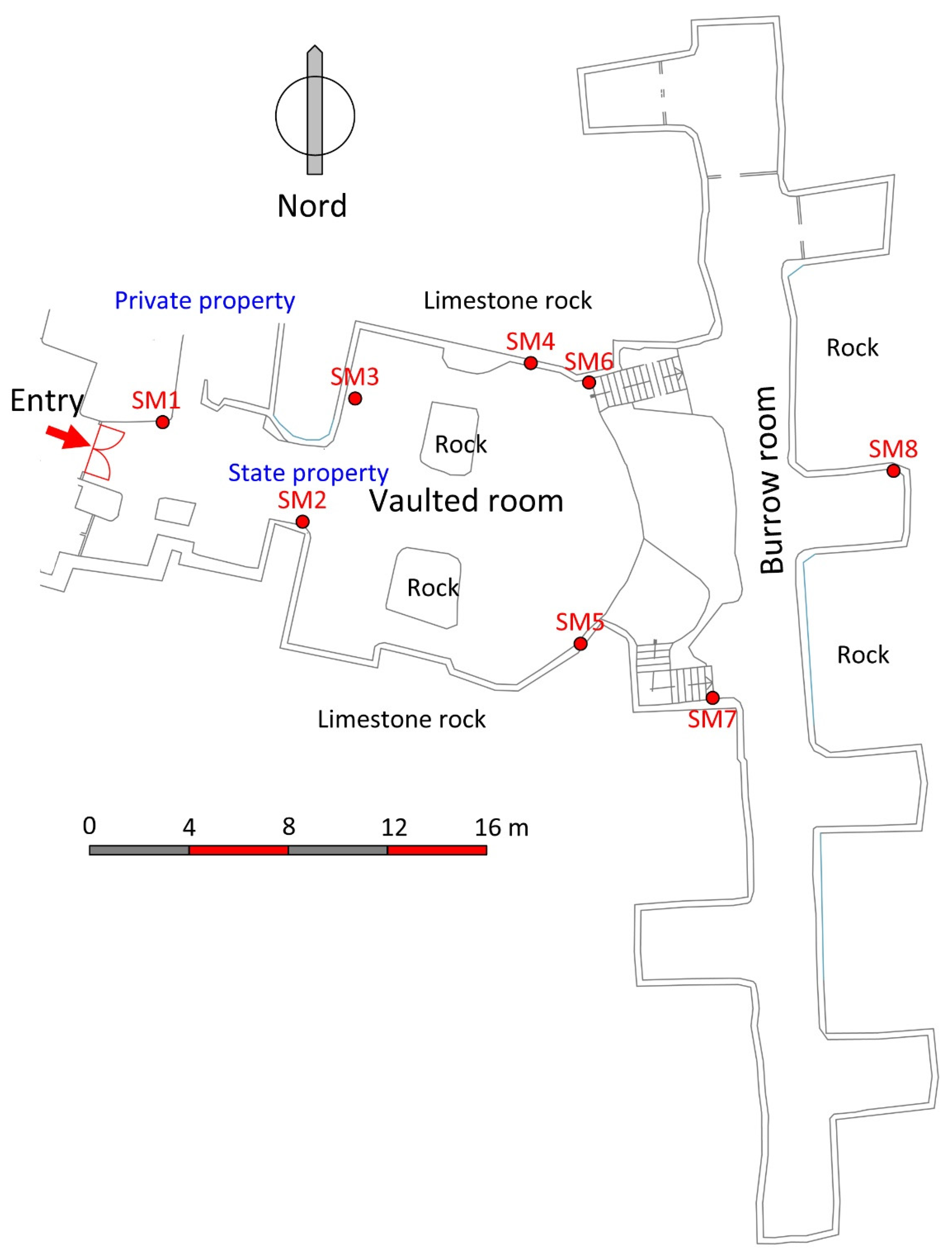
1.2. Location of Site in the Historical Context of Cagliari

Cagliari is the capital city of Sardinia and is located in the southern part of the island, which is situated in the middle of the Mediterranean between the Balearic and Tyrrhenian seas. The city is rich in history, of which numerous monuments still remain. These include those from the Neolithic period (domus de janas and some huts of the IV–III millennium BC), to the Phoenician–Punic period following the eighth century BC (e.g., founding ports near the pond of Santa Gilla, creating the Tuvixeddu necropolis, considered the largest Punic necropolis in the Mediterranean), to the Roman period, from 238 BC (with the important amphitheatre and suburban villas such as the so-called Villa di Tigellio), passing to the vandals in the mid-fifth century (in which the Basilica of San Saturnino was built, remodelled in the Romanesque period). The city was then reconquered by Justinian’s Eastern Romans in 534 AD and was again in Byzantine hands, until the Giudicale, period when the centre of the city became the village of Santa Igia (contraction of Santa Cecilia). Subsequently, with the arrival of the Pisans (1216–1217) and the destruction of the village of Santa Igia (1258), the centre of Cagliari became the current fortified district of Castello (hence the name of the city Castellum Castri de Kallari, Casteddu in Sardinian dialect), with the adjoining of the port of Bagnaria (later La Pola), connected to the Castle, through the current Marina district. In this period, several monuments were built, such as San Pancrazio (1305) and Elephant (1307, Figure 2a) Towers. Starting from 1323, the Aragonese besieged Cagliari, and built their stronghold on the southernmost hill of Bonaria where they settled a new port, leaving the Castle to the Pisans until 1325 when they completely conquered the city.
In the XV-XVII centuries, the important wall fortifications were built substantially close to the Castello district and are still observable today. The Spanish domination lasted until 1708, following the War of the Spanish Succession, with the arrival of the Anglo–Dutch and the various subsequent socio-political vicissitudes. Starting from the nineteenth century, after the unification of Italy, the fortification walls were demolished and the foundations were laid for the great expansion of the last century, with the participation of important architects, including Gaetano Cima and Dionigi Scano, who redesigned the urban centre according to the neo-classical and neo-gothic style, with the construction of the municipal building in Pietra forte, the characteristic liberty buildings, and numerous other palaces or buildings of historical and cultural interest. The site under study belongs to one of these twentieth century buildings, located in Piazza Yenne, one of the most important historical squares in Cagliari, located at the end of Largo Carlo Felice in the Stampace district. It represents the basement part (cave) of an historic building, excavated entirely within the outcrops of the most important limestone lithologies of the Cagliari area, namely the Pietra forte and the Tramezzario, which are found extensively along the slopes of the Castello hill. The site, called Grotta Marcello, was built in 1943 according to a project approved by the Military Authorities, for the construction of a large room to be used by citizens of Cagliari as air raid shelter during the Second World War. The works were carried out by the widening of a natural cavity, probably attributable to the karst process of the limestone rocks. The basement room includes a semi-circular central body with a vaulted roof (Figure 1b), with an area of about 180 square meters, from the bottom of which two branches branch off, which are opposite to each other and comprising six side niches, realised in later times. The floor area of the two aforementioned branches, including the niches, is 270 square meters. The cave, due to its importance it has had in the recent history of Cagliari and for its position in the building fabric of the historic city centre, and for the considerable interest it still has today, was declared in 2007 to be an “asset of cultural, historical and artistic interest” pursuant to Article 10 (paragraph one) of Legislative Decree No. 42 of 22 January 2004, by the Ministry for Heritage and Cultural Activities.

2. Limestone Rocks Outcropping in the Site

2.1. Geological Setting

Sardinia, together with Corsica, forms a continental microplate consisting of a Palaeozoic basement (Variscan metamorphics and syn-post Variscan granitoids) and widespread volcanic and sedimentary covers, from the Upper Carboniferous to Quaternary periods. The major thickness of unmetamorphosed covers are reached in an N-S trending depression known as Fossa tettonica sarda [57] or Rift of Sardinia [58,59], or the Sardinia Trough [60,61], that extends for 220 km (from the Sassari to Cagliari gulfs), and in the Campidano Plain, a Plio–Pleistocenic graben between the Cagliari and Oristano gulfs (Figure 3).
Four marine sedimentary cycles, associated with as many volcanic events, have occurred in Sardinia since the late Oligocene to the Pleistocene periods, leading to the deposition of thick volcano–sedimentary covers. The significance, the extent, the tectonic regimes, and the ages of these cycles are still a matter of debate leading, to different interpretations of the geodynamic scenarios and of the sedimentary environments (for instance, compare [58,60,61,62,63].
The area of Cagliari and its hinterland (southern Sardinia, Italy, Figure 3) is characterised by scattered outcrops of Miocene sedimentary covers, mainly represented by fossil-rich marine deposits, belonging to the second and third Oligo–Miocene cycles.
The Miocene series of the Cagliari area consists, from the bottom to the top, of the following formations: Marne di Gesturi Fm., Argille del Fangario Fm., Arenarie di Pirri Fm., and the mainly carbonatic succession known as Calcari di Cagliari Auct.
The Marne di Gesturi Fm. consists of a sandy to silty marls facies with arenaceous intercalations and a pyroclastic–epiclastic facies, of Upper Burdigalian to Middle-Upper Langhian age, referred to a bathyal environment. This formation is overlaid by the Argille del Fangario Fm. (Middle-Upper Langhian Lower Serravallian), consisting of a sequence of clay deposits of bathyal environment that, towards the top, become progressively more arenaceous, indicating a decrease of the bathymetric depth. The appearance of arenaceous littoral deposits belonging to the Arenarie di Pirri Fm., widely outcropping in the Cagliari area, marks the beginning of the third tectono-sedimentary cycle [63]. Based on fossiliferous content, the Arenarie di Pirri Fm. has been attributed to the Serravallian Early Messinian (?).
A new transgressive phase is testified by the marine succession known as Calcari di Cagliari Fm. (= Cagliari limestones) lying above the Arenarie di Pirri Fm. with transitional marly facies. The latter is further subdivided into three sub-units known as Pietra cantone Auct., Tramezzario Auct., and Pietra forte Auct. [64,65,66,67,68,69,70].
The Pietra cantone unit consists of yellowish marly–sandy limestones hosting abundant fossils that indicate a shallow marine depositional environment (60–80 m depth b.s.l.; [72]) and a Tortonian–Messinian age. A sharp, erosive surface separates the Pietra cantone from the above lying Tramezzario, comprising whitish biocalcarenites, which are locally marly. The abrupt change of biocenosis indicates the change of paleobathymetry (40 m according to Leone et al. [73]) that tends to decrease toward the top of the succession. The regressive tendency could have led to erosive processes, explaining the local absence of this unit. The top of the Miocene succession is represented by the Pietra forte facies, mainly characterised by biohermal whitish and compact limestones, locally massive, and subordinated biostromal limestones. Sedimentary structures suggest a littoral/infra-littoral environment with paleobathymetry lower than 30 m; fossils, although abundant, do not allow a precise age determination, however, based on its stratigraphic position, Pietra forte is referred to the Messinian age. The foundations and the walls of the ground floor of the studied building were carved into the in-situ limestones belonging to the Tramezzario (Figure 2b).

2.2. Use and Decay of Limestone Rocks in Historical Period

Sedimentary rocks (e.g., limestone, sandstone, etc.), particularly carbonate type, have been widely used in the construction of historical buildings in the Sardinian Island, as well as in many Italian or other monuments. This is generally due to their easier availability in the territory and especially to their better workability when compared to silicate igneous or metamorphic rocks [23,74].
The Miocene limestones outcropping in the Cagliari city area are frequently used in civil and historical architecture. The Pietra forte is a compact limestone with high physical–mechanical resistance, and therefore is hard to work (Figure 2a). The Pietra cantone (Figure 2c) is a marly limestone characterised by low cementing degree, high porosity (28-36 vol% [39]), and, for these reasons, by an easy workability. The Tramezzario is a more compact limestone with intermediate petrophysical behaviour. For these reasons, and given their wide availability in the territory around Cagliari, Tramezzario and Pietra cantone limestones have been widely used in historical buildings (Figure 2) of all periods, from Nuragic, to Phoenician–Punic, Roman, and medieval [75]. Pietra cantone owes its name to the ashlars (= cantone) being remarkable easy to be cut and squared off [76].
When these limestones are used on monuments in the presence of humidity or circulating aqueous solutions, they frequently undergo decay problems [39]. The chemical–physical decay is due to hygroscopic volume variations of clay minerals and sea salts in the rock, as well as to the dissolution and re-precipitation of calcite that make the limestone easily degradable and subjected to decreases in mechanical strength. When the limestone is used in the structural elements of monuments (e.g., ashlars in the wall, column, jambs), decay can lead to the formation of serious static–structural criticality in the buildings, as a strong retreat of vertical profile of the facade or detachment of material portions from the decorative elements, due to exfoliation and flaking processes (Figure 2d).
To prevent such a decay of carbonate rocks used in the monuments, numerous efforts regarding their water protection and surface consolidation have been necessary since ancient times and solutions can be retrieved thanks to laboratory experimentation. These chemical treatments differ both in the typology of products and in application methods. However, due to the different chemical–physical–petrographic characteristics of these lithologies, microclimatic conditions, and the alteration degree of the artefacts, the conservative techniques must be adapted to each case individually.

3. Materials and Methods

The survey was carried out according to the following operative phases: (i) architectural reading and analysis of the structural aspects (plan distribution, building systems, wall); (ii) in situ mapping of the macroscopic characteristics of geomaterials and their stratigraphy on the wall, including the decay forms and conservation state; (iii) sampling of materials, in agreement with the representativeness of each plaster layer (according to Recommendations Nor.Ma.L. 3/80 [77]); (iv) mineralogical—petrographic investigations by optical microscopy, X-ray powder diffraction (XRD) and by SEM-EDS microanalysis; (v) physical and mechanical analyses (porosity open to helium and water, real and bulk density, water absorption kinetic, imbibition coefficient, saturation index).
30 mortar samples (in some cases including the limestone substrate) were taken from eight different points (labelled from SM1 to SM8, Figure 4 and Figure 5) of the building walls.
The sampling was carried out both at the surface of plaster layers and on the less altered rock substrate. The material was collected from the shallow parts of the masonry, according to the recommendations of the local Superintendence of Cultural Heritage, which imposes strict limits on the quantity of sample to be collected. The volumes collected are, however, representative and adequate for the analytical studies.
From each sample, the following were realised: 30 μm thick, polished thin sections for optical and electron microscopy; prismatic-like specimens for determining the physical and mechanical properties; a small aliquot of finely ground and homogenised powder for determining some physical properties (see below) and the mineral assemblage by XRD.
Physical tests were carried out according to [43] and [78,79]. The specimens were dried at 105 ± 5 °C for 72 h, then the dry solid mass (mD) was determined by an analytical balance with four decimals.
A helium pycnometer (Ultrapycnometer 1000, Quantachrome Instruments) was used to determine the solid phase volume (VS) of 5–8 g of powdered rock specimens (fraction less than 0.063 mm), and the real volume (VR = VS + VC, where VC is the volume of pores closed to helium) of cubic specimens (side of 15 mm).
The wet solid mass (mW) of the samples was determined after water absorption by immersion for ten days. The hydrostatic mass of the wet specimen (mHy) was measured by a hydrostatic analytical balance and was then used to calculate the bulk volume (VB) as follows:
VB = [(mW − mHy)/ ρWTX]•100
where ρWTX is the water density at a TX temperature.
VB is the bulk or apparent volume of the sample, resulting from the sum of the volumes VS + VO + VC (solid phases, open pores and closed pores to helium, respectively). Thus, the volume of pores open to helium can be easily obtained as VO = (VB − VS − VC) = (VB − VR).
Total porosity (ΦT), open porosity to water and helium (ΦOH2O; ΦOHe, respectively), closed porosity to water and helium (ΦCH2O; ΦCHe), bulk density (ρB), real density (ρR), were calculated as:
ΦT = [(VB − VS)/VB]•100
ΦOH2O = [(mW − mD)/ ρWTX]/VB]•100
ΦOHe = [(VB − VR)/VB]•100
ΦCH2O = ΦT − ΦOH2O
ΦCHe = ΦT − ΦOHe
ρR = mD/VR; ρB = mD/VB
The weight imbibition coefficient (ICW) and index of saturation (SI) were calculated as:
ICW = [(mW − mD)/mD]•100
SI = (ΦOH2O/ΦOHe) = [(mW − mD)/ ρWTX]/VO]•100
The image analysis was performed by the JMicrovision v1.3.3 software, in order to describe and quantify the binder/aggregate (B/A ratio) of the mortars under study, to detect their porosity, and finally to classify the mortars on the basis of these parameters. In the case study, a “Point Counting” was used, that is a count of the points of an image, differentiating three classes in three different colours: binder (red colour); aggregate (green colour); macro-porosity with average pore radius > 50 μm (yellow colour). By setting the total point count on the image with a number equal to 750 units, the different percentages of the classes set on JMicrovision were determined.

4. Results

4.1. Compositional Characterisation of Mortars

4.1.1. Classification of Samples

Based on macroscopic and microscopic observation, compositional aspects, and technical–constructive function, the samples have been grouped into three categories (Table 1):
(1)
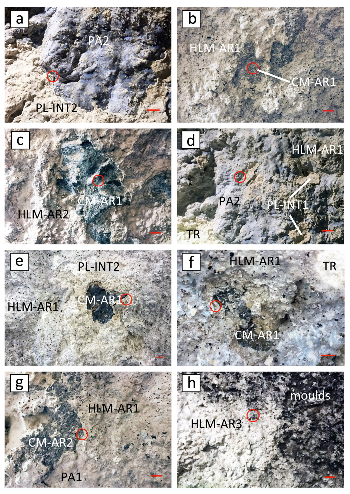
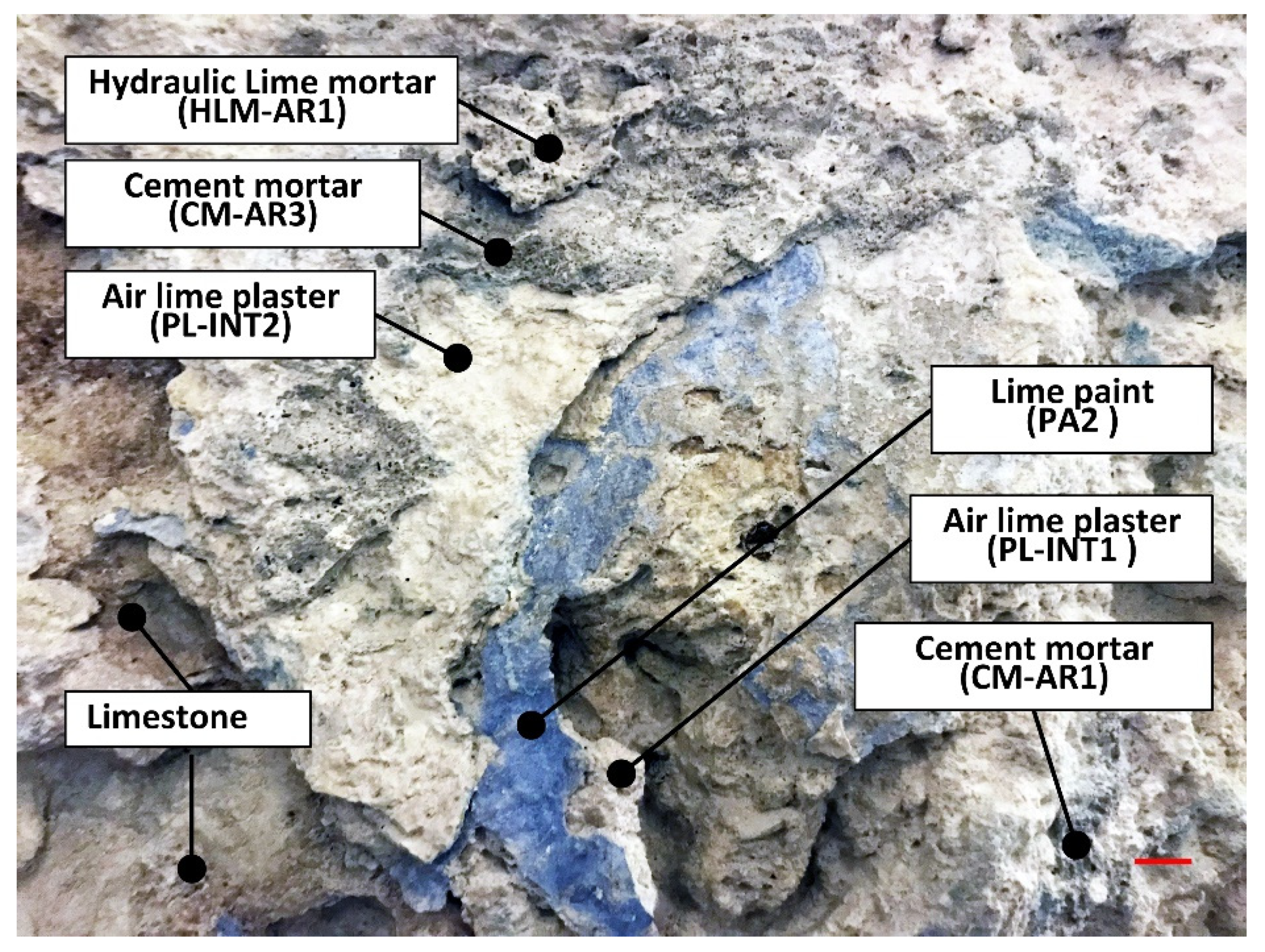
Cement mortars (signed as CM) are present unevenly in the cave inner wall, and sometimes are also used for the installation of hydraulic or lighting systems, or to fill wall voids and/or to consolidate fractures and discontinuities (Figure 5b,c,g). They are characterised by a typical greyish to brown-grey cement-based binder (thus with high hydraulic degree) and a silicate aggregate (mainly quartz and feldspars). During the sample collection they appeared quite hard, suggesting heavy mechanical strength. Two types have been distinguished from the binder/aggregate ratio (B/A) measured by image analyses: CM-AR1, with an average B/A of about 56:42%, and CM-AR2, with a B/A of 67:20%.
(2)
Hydraulic lime mortars (signed as HLM), consisting of fine-grained quartz and feldspar aggregates (Figure 5b,e–g) and a whitish hydraulic lime binder, according to the EN 459-1:2015 standard [80] can be classified as HL mortars. Mechanical strength and hydraulic grade appear to be lower than those of cement mortars. All HLM samples look quite similar in grain-size, colour, and B/A but strongly differ in thickness; this parameter has been chosen to distinguish the three categories, and to evaluate if different HLMs were employed to achieve different thicknesses.
(3)
Finishing plasters (intonachino, signed as PL) consist of fine aggregate and a lime (or feebly hydraulic)-based binder with very low mechanical strength (Figure 5a,d,h). According to the EN 459-1:2015 standard [80], the PL samples can be classified as air lime plasters. PL samples have been subdivided into three types depending on their macroscopic aspect, on the adhesion to the substrate and on their “stratigraphic” position.
If considering the function of mortars, two categories can be identified:
-
arriccio layers (AR) are the plasters with coarse-grained aggregate (mainly ranging in 1–2 mm) used to fill voids and fractures, to flatten the rock substrate, and to create a rough surface that allows the grip of the finishing plaster. They are commonly 7 to 12 mm thick but can reach 25–30 mm when used as filler for voids. The AR binder layers can be either cement or hydraulic lime and they were found to be applied directly on the rocky substrate or above older plasters.
-
intonachino layers (INT) are the finishing plaster characterised by finer aggregates (<0.5 mm) and a low thickness (2–4 mm). They usually adhere to the AR layer, although one sampling point was found to lie directly on the rock substrate. All INT layers have a lime-based binder and a little amount of fine aggregates.
In addition, four coats of paint, alternating between the INT plaster layers, were found. The coats’ thickness is commonly lower than 0.5 mm and shows a strong adhesion to the underlying plaster. These coats have not been analysed, but a rough observation indicates a lime-based matrix for three of them, whereas the last, fourth one seems to have another composition (with acronym PA).

4.1.2. Stratigraphy of Plasters and Decay

The complex stratigraphy is the result of the superimposition of several restoration interventions performed with different mortar materials, different aims (fill voids, uniform the surface, limit humidity, aesthetic improvement, etc.), and in different times. Moreover, many of these interventions were just patchy-like repairs that did not involve the whole wall surface and consisted of re-plastering with or without removing the older underlying plasters, which had, in some cases, partly detached due to the decay, or well adhered somewhere else. Thus, the eight samples (SM1 SM8) collected in different points of the cave room (Figure 5) showed significant differences in the sequence substrate/plaster/paint and different macroscopic forms of chemical–physical decay. The lower one is represented by the rocky substrate, constituted by Tramezzario (TR) and subordinately by a stronger limestone (TR-S), with similar characteristics to the Pietra forte limestone, while the Pietra cantone was not found.
A general scheme of the plasters’ sequence, from the limestone substrate to the surface, is summarised as follows and is shown in Figure 6 and in the synoptic scheme of Figure 7.
Layer (1): cement mortars (signed as sub-layers CM-AR1 and CM-AR2), locally present in the rocky wall of the cave and generally in direct contact with the substrate; occasionally, a third layer (CM-AR3, not sampled) over the following plaster layers could be observed. CM consists of grey to dark grey cement-based mortars with millimetre-sized aggregates, used as arriccio, often showing saline efflorescence;
Layer (2): a very fine-grained air lime plaster, probably based on aerial lime; it was labelled as PL-INT1 (intonachino) and used as a finishing plaster. Where cement mortars are absent, INT1 is absent too, except for one sample where INT1 lays directly on the rock substrate. Over this layer there is a painting coat with lime composition, characterised by beige (PA1) and light blue (PA2) colours;
Layer (3): a finishing coat represented by a millimetre-thick intonachino level (PL-INT2), lime-based and almost free of aggregates;
Layer (4): a hydraulic lime mortar (arriccio layer, named as HLM-AR1), which represents a plaster coat applied in a more recent restoration and is composed of a hydraulic lime with millimetre-sized, light beige aggregates;
Layer (5): the second arriccio layer of hydraulic lime mortar (HLM-AR2), that has undergone further plastering intervention that, such as the previous one; it was based on hydraulic lime binder; however, it can be distinguished by the finer grain-size of its aggregates; the fourth layer of arriccio (HLM-AR3) has been found in only one sampling point, probably used to fill some void or surface irregularity;
Layer (6): a light grey finishing plaster (PL-INT3), 2 mm thick due to the last intervention that lies above HLM-AR2, characterised by few, very fine-grained aggregates and a lime binder.
In addition, a light beige coat-paint (PA3), probably lime based, has been found, with a semi-transparent paint of different composition appearing above.
The paint coats have not been studied but were extremely useful to distinguish between the different plastering interventions, since they act as markers of the different phases, allowing us to recreate a synoptic scheme (Figure 7).
In regards to the decay of materials, the limestone and plasters of the wall cave-room often showed decohesion and the presence of fano- (on the surface) and crypto-efflorescence, due to the constant presence of humidity and/or circulating aqueous saline solutions in the rock. The cyclic mechanisms of hydration/dehydration and solubilisation/crystallisation of salts produce a hygroscopic volume variation in the limestone with consequent exfoliation and flaking. The degradation apparently manifests itself in the same way on all mortar layers, regardless of their composition. However, it was observed that for CM cement-based mortars, by virtue of a different physical–mechanical behaviour characterised by a higher mechanical strength, that when the process of decohesion and spalling has occurred, the detachment of larger flakes was noted. HLM mortars showed less frequent detachment of material which, in any case, is of minor entity (thin and localised flakes). The intonachino plaster layers (PL-INT), having very thin thicknesses, tend to exfoliate and detach from the substrate only where there is constant moisture from the inside of the rock towards the interior of the cave-room. Moreover, HLM and especially PL-INT also showed sulphation processes, with the formation of gypsum.

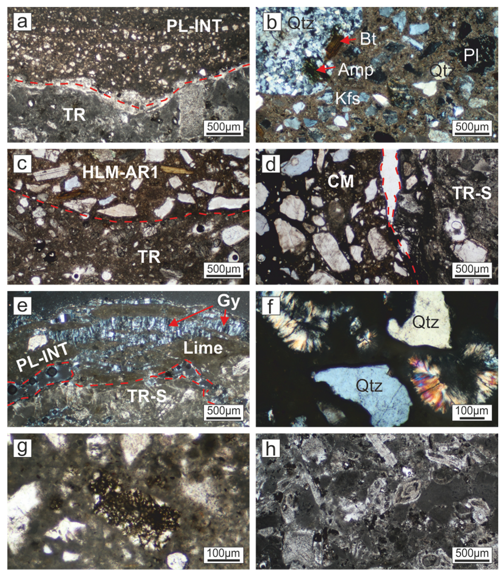
4.1.3. Petrographic Characteristics

The observation of thin sections under a polarised microscope allowed us to identify the petrographic characteristics of limestone substrate and plasters, defining the kind and size of aggregates and the binder/aggregate ratio in mortars (Figure 8). However, it was not very effective in recognising the nature of the binders, since they is cryptocrystalline or amorphous and commonly affected by degradation phenomena, such as oxidation of Fe-bearing phases, dissolution/precipitation of secondary phases, or development of brownish-grey stains of undefined origin (probably due to the deposition of impurities by circulating fluids).
Binders of mortar and finishing plaster samples are commonly whitish (PL-INT) to greyish (HLM-AR, CM-AR2, CM-AR3), to brownish (CM-AR1), and locally preserves lumps of unmixed slaked lime mainly found within arriccio layers.
The most evident feature that allows a discrimination between the different mortar mixtures is in the size and number of aggregates. PL-INT layers are characterised by homogeneous and very fine aggregates, having a fairly constant grain-size (0.05–0.1 mm) and mineralogy mainly consisting of rare quartz and minor feldspars (Figure 8a). On the contrary, HLM-AR layers are characterised by 0.2 to 4 mm sized aggregates, mainly consisting of quartz and feldspars, but including also minor amounts of poly-mineral lithoclasts, (belonging to metamorphic and igneous rocks), pyroxenes, amphiboles, micas, and marine fossil skeletons (Figure 8b). This complex assemblage suggests a polygenic origin and different sources of aggregates supply used for arriccio hydraulic lime mortars. Medium-coarse aggregate fraction (0.3–4 mm) of CM-AR layers consists of quartz, K-feldspar, plagioclase, biotite, pyroxene, titanite, occasional lithoclasts, marine fossils of different origin, and other accessory minerals not identifiable by polarised microscope.
The contact between cement/hydraulic lime mortars and limestone substrate of the cave-room differs depending on the nature of the binder. Hydraulic lime mortars (HLM-AR) adhere quite well on the substrate (Figure 8c) and neither discontinuities nor secondary phases were detected along the contact. Cement-based mortars (CM-AR1, CM-AR2), on the contrary, are commonly detached from the substrate and the contact is marked by discontinuous elongated fractures (Figure 8d). PL-INT layers, although based on a lime binder, did not show a good adhesion with the limestone substrate. Indeed, fractures running along the contact and filled by gypsum growing perpendicular to it (Figure 8e) were found in several microdomains.
The observation under optical polarised microscope revealed the formation of secondary minerals within the cement mortars. Acicular crystals of ettringite and/or thaumasite have been found in fibrous radial aggregates with sizes smaller than 0.5 mm (Figure 8f). In addition, several clusters of micrometre-sized rounded crystallites, surrounded by a matrix of opaque minerals (mainly titanite) were also found (Figure 8g).
Tramezzario samples of limestone substrate are characterised by a micritic matrix, in which a high amount of bioclastic grains (especially bivalves, foraminifera and algae) could be found (Figure 8h). Sparite crystals are quite rare. Based on the Folk’s classification (Folk, 1959), the analysed samples are fossiliferous biomicrite whereas, according to Dunham (1962), they can be regarded as wackestone, locally tending to packstone. Thin section observation allowed also a first estimate of the porosity that ranges between 10 and 15% and appeared as single voids, probably due to dissolution phenomena or, more rarely, as a network of thin channels and fractures, some of which could have been produced during the sampling.

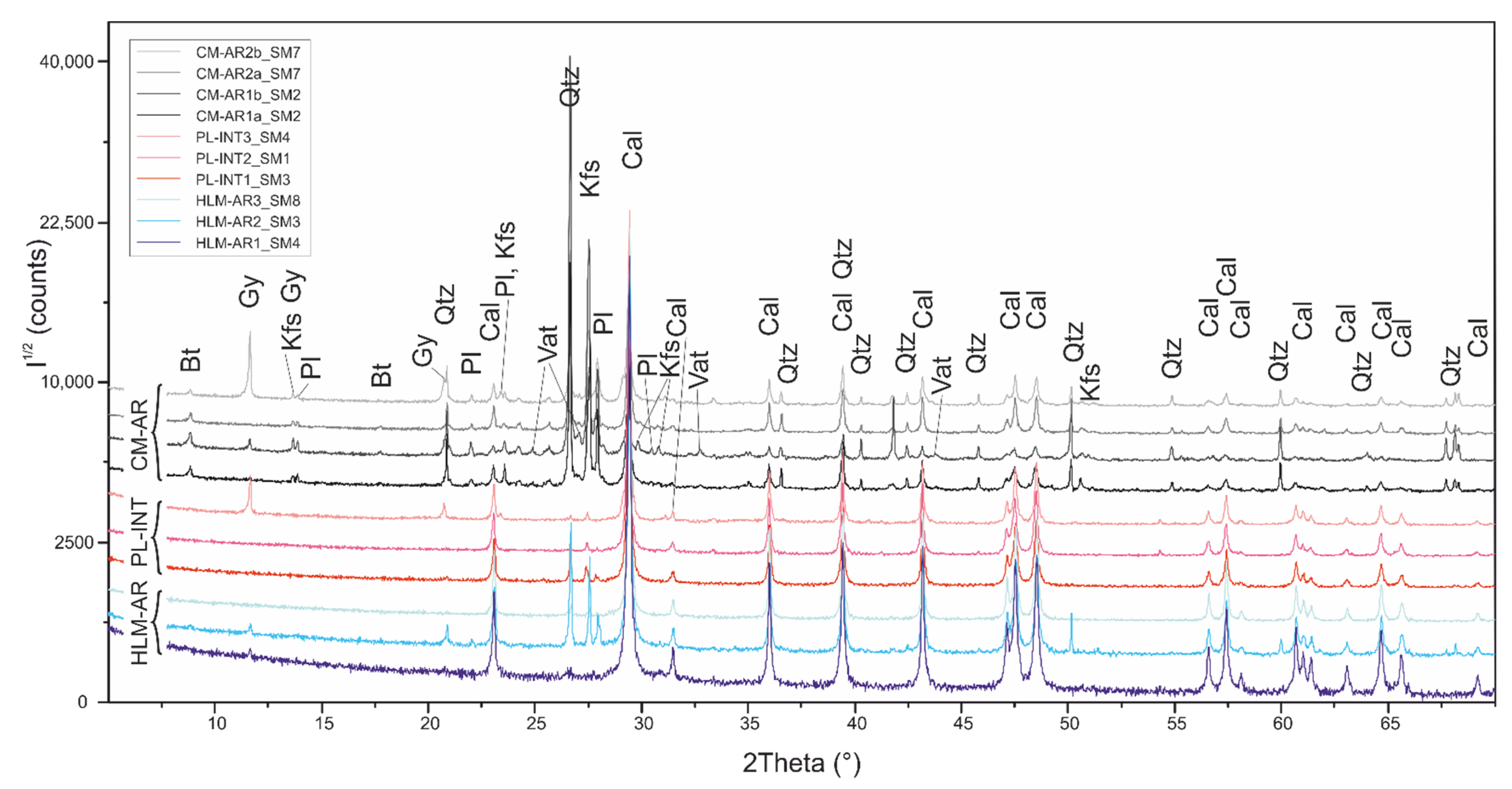
4.1.4. X-ray Diffraction

The results of the XRD analysis of plaster samples collected from the wall surface of rocky cave room are summarised in Figure 9.
Samples HLM-AR1 and HLM-AR3 consist almost totally of calcite, with traces of quartz recognised just by the most intense peak. HLM-AR2 as well mainly consists of calcite with subordinate quartz whose content is higher than the previous samples; furthermore, K-feldspar, plagioclase, and gypsum were detected by their most intense peaks.
PL-INT samples are quite similar to HLM-AR ones, being mainly composed of calcite and minor quartz, feldspars, and gypsum. However, their patterns show some differences, such as a lack of quartz in PL-INT2, the higher amount of gypsum in PL-INT3, and the different relative abundances of K-feldspar and plagioclase. In addition, PL-INT2 and PL-INT3 show a small peak at about 54.3° 2θ, not detected in the other samples, which do not clearly match to any phase in the database.
CM-AR samples show an aggregate composed of variable amounts of quartz, K-feldspar, plagioclase, and biotite, thus comprising a mineral assemblage resembling the other samples. However, several differences are evident, such as the higher amount of quartz and feldspars, the presence of biotite, and the higher noise of the background signal that suggests lower crystallinity for the presence of C-S-H and C-A-H phases in the binder. The binder also consists of calcite (often altered for sulphation in gypsum), having a low crystallinity when compared with the PL-INT and HLM-AR samples. This is testified by the peak’s shape (Figure 9), commonly showing lower intensities and higher values of FWHM (full width at half maximum). The stronger intensities of quartz and feldspars indicate the lower B/A ratio in CM samples than in PL-INT and HLM-AR samples.
The four samples of the CM group share similar patterns except for CM-AR2-B and CM-AR1-B, showing abundant gypsum and weak peaks matching to the vaterite (metastable calcite polymorph) reference pattern, respectively.

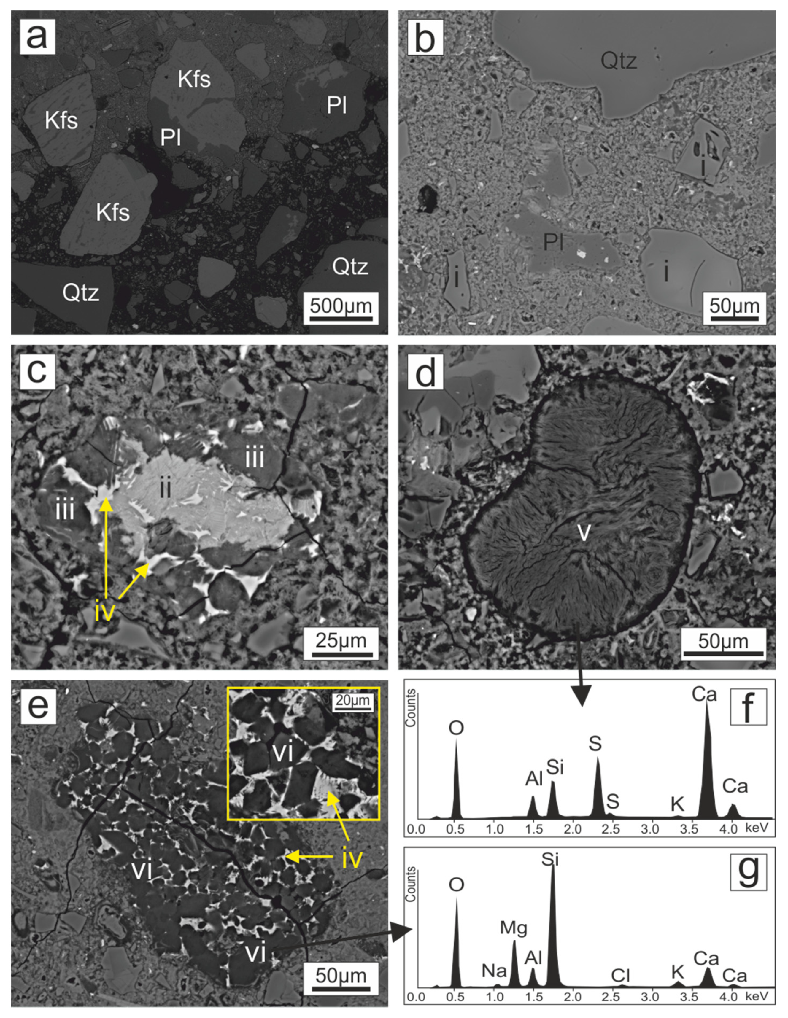
4.1.5. SEM Imaging and EDS Analyses

Three thin sections, representative of the different mortars (CM, HLM, PL; Figure 10 and Figure 11), were analysed by SEM-EDS to observe the microstructural relationship between binder and aggregates and to identify the nature of the microcrystalline binder, not detectable by optical microscopy.
SM5 thin section comprises a part of limestone substrate (Tramezzario, TR) in direct contact with a coarse-grained hydraulic mortar (HLM-AR1) and a thin layer of fine-grained intonachino (PL-INT2). The rock mainly consists of microcrystalline calcite with rare fossil skeletal fragments and gypsum. The aggregates of the hydraulic mortar are heterogeneous in size (0.1–1 mm) and polygenic (Figure 10a); indeed, grains of calcite, quartz, plagioclase, biotite, K-feldspar with perthite exsolutions, and clasts of mafic rocks (formed by Ca-rich plagioclase, pyroxenes, titanite) were found to be mixed together.
The binder consists of 0.3 to 1.5 mm sized plagues consisting of massive calcite (Figure 10b) and rounded calcite crystallites (Figure 10c), with interstitial Si-Al-Ca-rich hydrated phases (C-S-H, C-A-H). This has been confirmed by EDS spectra collected on the binder, suggesting the presence of calcite even if, in each analysed point, little amounts of Si and Al were detected (Figure 10d). The thin layer of fine-grained intonachino PL-INT2 (Table 1) is non-homogeneous in composition, as highlighted by the BSE imaging showing alternating darker (calcite) and lighter (calcite + gypsum) levels (Figure 10e). The contact between HLM-AR1 and PL-INT2 is locally marked by micrometre-sized fractures filled by fibrous gypsum crystals growing perpendicular to the interface (Figure 10f).
The SM2 thin section contains a small part of the strong limestone substrate of Tramezzario (TR-S), in direct contact with the cement mortars CM-AR1 (Table 1). According to the results of the polarised microscopy analysis, the aggregates consist mainly of submillimetre- to millimetre-sized grains of quartz and feldspars, with minor biotite and rare calcite. K-feldspar shows perthite exsolutions and is commonly altered to sericite. Plagioclase is oligoclase or rarely andesine with a variable degree of sericite alteration. Accessory phases are epidote, commonly found among the aggregates, and titanium oxide, locally found within quartz grains. Rare poly-mineral grains and fossils were also observed. The binder showed a microcrystalline texture, where the hydrated Ca-rich calcium silicates and aluminates (C-S-H, C-A-H) and rare calcite were observed that appeared as clusters of subrounded grains. The EDS spectra revealed the presence of little and variable amounts of Mg, Si, and Al probably deriving from C-S-H and C-A-H and from impurities of the raw marly–limestone used for cement production.
The SM6 thin section mainly consists of cement mortar (CM-AR1-A, CM-AR1-B, Table 1) and a small fragment of TR limestone substrate. The two parts are separated by a 0.3–0.5 mm wide fracture and a thin calcite layer (0.2–0.4 mm) that rims the substrate. The aggregates are heterogeneous in size (Figure 11a), however, in contrast to SM2 sample, they are not polygenic; they consist of quartz, oligoclase, and perthitic K-feldspars, plus accessory phases such as zircon and Fe-Ti, suggesting a granitoid source. BSE imaging on the cement binder revealed a microcrystalline texture (Figure 11b) and different shades of the grey-scale, indicating the coexistence of different phases, further supported by EDS microanalyses. Although EDS analyses are not accurate enough to determine the stoichiometry of these phases, the relative proportions of the major elements and the semiquantitative chemical data allowed us to distinguish the main constituents of the binder. Among tens of analyses, the following phases were distinguished:
(i)
anhedral to subhedral grains (commonly micrometre-sized but locally reaching 100 μm; Figure 11a,b) of Si-rich Al-silicates (SiO2 ~ 66 wt.%, Al2O3 ~ 13 wt.%, K2O ~ 5 wt.% with 2–3 wt.% of both CaO and Na2O) resembling the composition of a zeolite, specifically a K-rich mordenite;
(ii)
C-S-H fibrous aggregates of hydrated Ca-rich calcium silicates, attributable to the hydrated alite (according to Cement Chemist Notation acronym: C3S = 3CaO•SiO2) and belite (C2S = 2CaO•SiO2, with CaO = 58–59 wt.% and SiO2 = 32–34 wt.%) phases typical of cement, with minor amounts of Al, Na, Mg, and K oxides (Figure 11b);
(iii)
anhedral subrounded grains of hydrated Si-rich calcium silicates (CaO = 33–35 wt.% and SiO2 = 32–34 wt.% = CaO•SiO2), with subordinate amounts of Al, Mg, and Fe oxides (Figure 11c);
(iv)
mixed phases of C-A-H and C-S-H (as hydrated mono-calcium aluminate and type iii phase) and of C4AF phases (with formation of aluminates (C-A-H) and ferrites (C-F-H) hydrates), overall, mainly consisting of CaO = 43–44 wt.%, Al2O3 = 18–20 wt.%, Fe2O3 = 17–18 wt.%, and SiO2 = 10–14% (Figure 11c);
(v)
subrounded aggregates of fibrous crystals (Figure 11d) made up by CaO ~ 34 wt.%, SO3 ~ 22 wt.%, SiO2 ~ 11 wt.%, and Al2O3 ~ 6 wt.% that approximate the composition of a ettringite–thaumasite-like phase, derived by a reaction between the Ca-alluminates and the gypsum used to delay the setting of the cement;
(vi)
clusters of subhedral micrometre-sized (10–20 μm; Figure 11e) grains of magnesium silicates (SiO2 ~ 60–65 wt.%, MgO ~18 wt.%, CaO ~ 6–9 wt.%, Al2O3 ~ 5 wt.%; Figure 11f) with interstitial fibrous phases with composition similar to iv);
(vii)
rare anhedral calcite grains randomly distributed within the binder, derived by the carbonatation of residual Ca(OH)2, produced by the hydration reaction of alite (C3S) and belite (C2S) phases.

4.1.6. Binder/Aggregate Ratio of Mortars

The analysis of the microscopic images of the sampled plasters allowed us to determine the binder–aggregate ratio (B/A) expressed in vol.% (Table 2). The count did not include the coarser aggregate (>6 mm) occasionally present in the mortars, and the very fine aggregate (<50 μm), which not well observed in the selected images (Figure 12) and therefore not included in the black/white binarisation of the microscopic images. The analysis also allowed us to determine the porosity (Table 2), but, for the same reasons as mentioned above, the calculation did not include fine and coarse mesoscopic porosity.
Since the CM mortars are curl layers with higher thicknesses and, therefore, represent a different mixing of the parts, where, therefore, a higher amount of aggregate is required, they showed a lower B/A than all the samples, equal to about 3:2, with an average binder value of 58.2%. The curl layers of the HLMs, which also typically have smaller thicknesses (Figure 12), showed a slightly higher B/A of about 2:1, with an average binder value of 69.2%. The PL-INTs, by virtue of their finishing function with much smaller thicknesses (usually millimetric, Figure 12), where the layers are very thin and the aggregate has a much finer grain size, show a much higher B/A of about 9:1, with average values of 89.8% in PL-INT1, 84.4% in PL-INT2 and 87.4% in PL-INT3 samples.

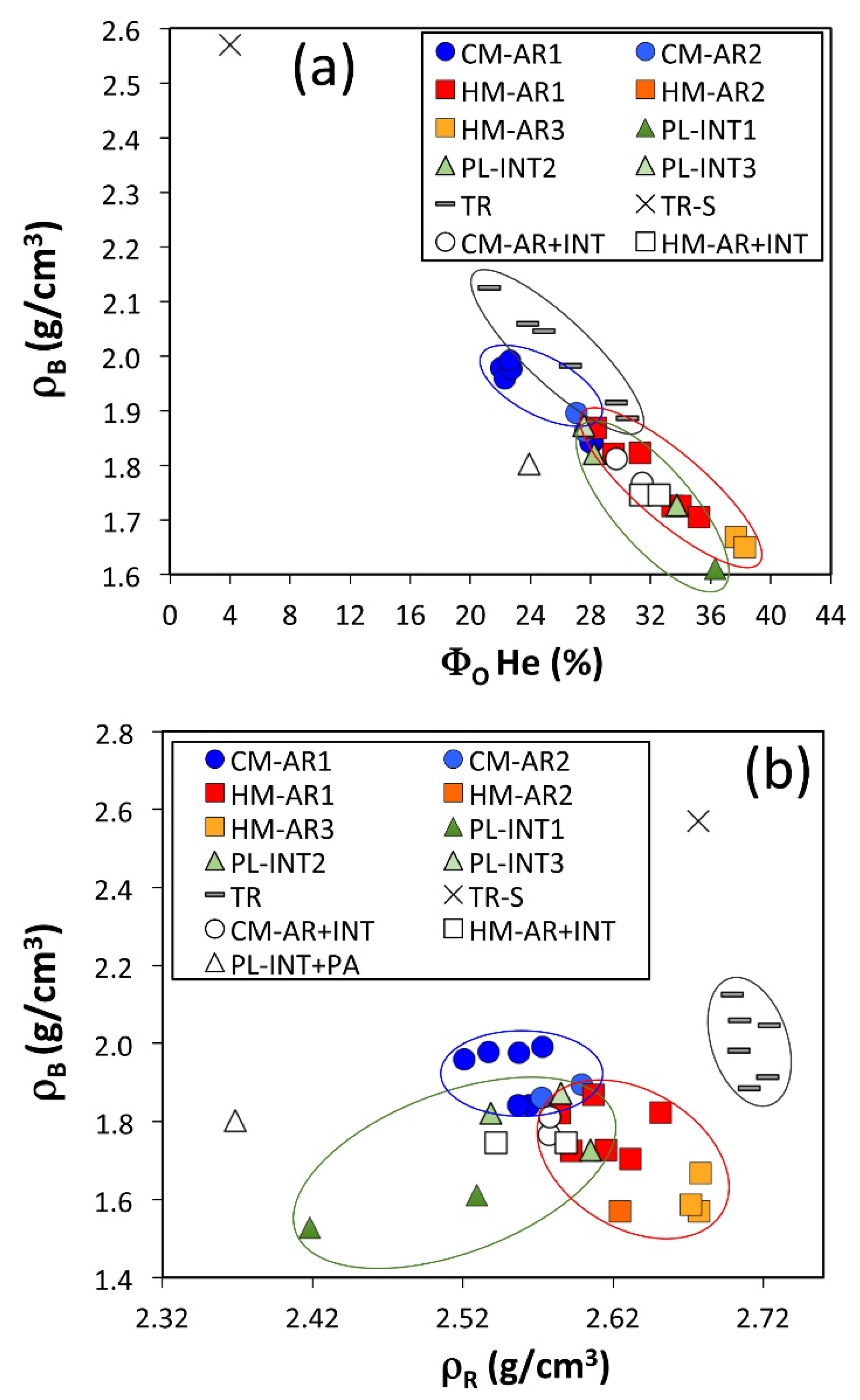
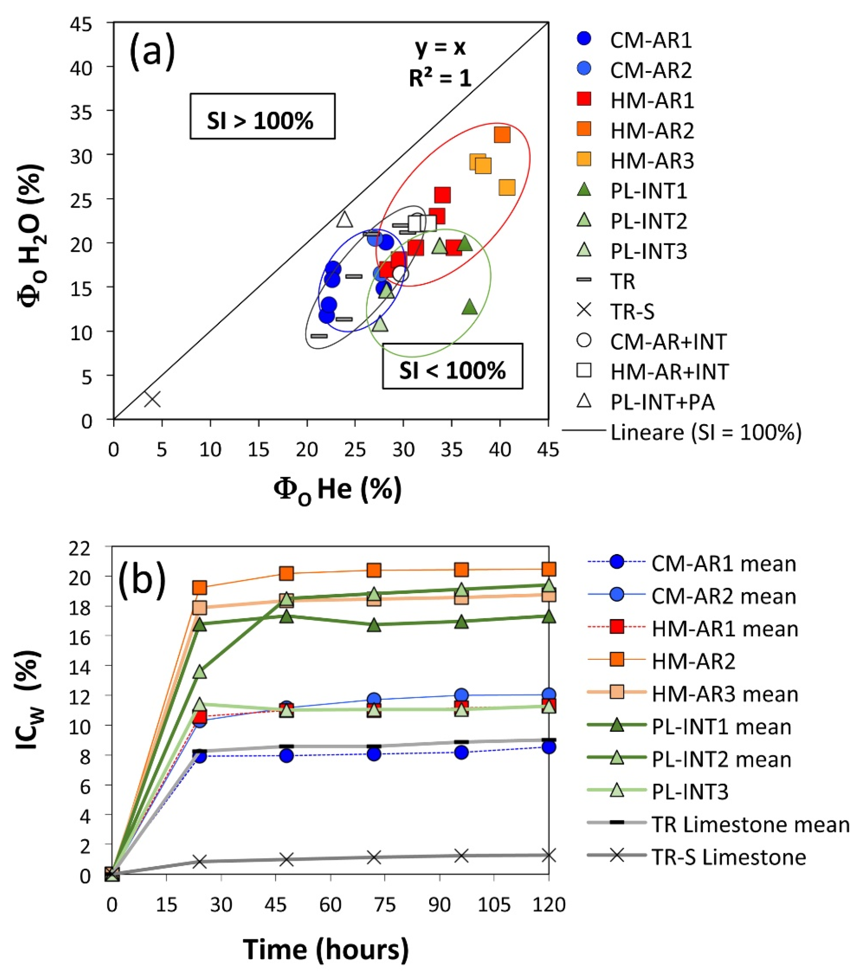
4.2. Physical Properties

4.2.1. Plaster Samples

The following petrophysical properties of plaster samples were analysed: real and bulk density, porosity open to water and helium, water absorption kinetic, imbibition coefficient, water saturation index. Data are reported in Table 3.
The real density (ρR), which is controlled by the density of solid phases and by the closed to helium porosity, ranged between the average values of 2.55 ± 0.02 g/cm3 and 2.59 ± 0.02 g/cm3 for the cement mortars CM-AR1 and CM-AR2, respectively (Table 3; Figure 13b). The hydraulic lime mortars showed higher real densities, ranging from 2.61 ± 0.02 g/cm3 in HLM-AR1, to 2.62 g/cm3 in HLM-AR2, to 2.68 ± 0.003 g/cm3 in HLM-AR3. The real density of finishing air lime plasters (PL-INT) has lower values than the other mortars, ranging between 2.47–2.57 g/cm3.
Considering the aggregate mineralogy (mainly quartz and feldspar with density of 2.65 and 2.5–2.8 g/cm3, respectively) and the binder/aggregate ratio, which are similar for both CM and HLM, the difference in real density values must lie in differences between the density of the binder.
The lower real density of CM can be ascribed to the presence of C-S-H and C-A-H phases (i.e., hydrated calcium silicates and aluminates), which are typical of cement. Completely cured cements, as the here-studied ones, are usually composed by:
(1)
calcium silicate hydrate, known as C-S-H (I), with a tobermorite-like crystal structure, and C-S-H (II), with a jennite-like structure [81,82], having densities of 2.23 and 2.33 g/cm3, respectively [83];
(2)
calcium aluminate hydrate C-A-H as C3AH6 and C4AH13, with density 2.04 g/cm3 whose formation implies the presence of portlandite C-H, having a density of 2.26 g/cm3 [84].
Furthermore, the hydration reactions occurring in cement mortars produce a porous structure, mainly made by non-interconnected micropores [85], in which He is not able to penetrate, possibly leading to underestimations of the real density.
On the contrary, HLM samples mainly consist of calcite (2.71 g/cm3) and subordinate vaterite (2.66 g/cm3), derived from the C-H carbonation; the low amount of C-S-H and C-A-H phases, barely detected by EDS microanalyses, as Ca-rich phases with low Si and Al contents, suggests a feebly hydraulic behaviour of these mortars and excludes a significant contribution of these phases to the measured density values.
The low real density of finishing air lime plasters (PL-INT) is an unexpected feature, since these mortars are characterised by calcite binder and quartz–feldspars aggregates, and thus they should have densities higher than approximately 2.6 g/cm3. A possible explanation of parameters that reduce the real density are the presence of gypsum (density = 2.36 g/cm3) and/or the wide presence of very fine intracrystalline porosities that, considering the low number of aggregates, are likely to be closed, leading us to overestimate the samples’ volume.
As regards the bulk density, the higher values were found in CM samples (1.88–1.93 g/cm3), whereas the lower ones were detected in HLM (1.57–1.78 g/cm3) and PL (1.57–1.77 g/cm3) samples (Table 3, Figure 13a). The higher bulk density in those samples showing the lower real density is explained by the lower open-to-helium porosity in CM (24–27%) than in HLM (32–40%) and in PL-INT (31–37%). The open-to-water porosity, as expected, is lower than open-to helium one in all mortars, having values of 15-18% in CM, 17–25% in HLM, and 16–17% in PL (Table 3, Figure 13b).
The degree of saturation (SI) ranges between 64–72% in both CM and HLM samples and is significantly lower in PL samples (45–55%), further confirming the statements above regarding the more packed and closed structure of PL.
At the end of the 120 h long absorption test for water immersion, the samples were positioned under the line of 100% (Figure 14a), with a mean of saturation index ranging from 39.7 to 55.2% in PL-INT samples, from 63.8% to 80.3% for HLM samples, and from 63.7% to 67.8% in CM mortars (Table 3, Figure 14a).
The absorption kinetic of water (Table 4) is shown in Figure 14b. Almost all CM and HLM samples reach the 80% of the maximum absorbed water after 24 h, then the absorption continues slowly and constantly. In PL samples, although most of the water absorption occurs within the first 24 h (as well as the other samples), a significant and discontinuous increase was observed after longer and variable times.
This suggests that PL are characterised not only by a low open-to-water porosity but also by a certain tortuosity of the pore network that makes it difficult for water to enter within the plaster layer. It cannot be excluded that wall painting, mainly applied on this render plaster, could have contributed to prevent water entrainment.

4.2.2. Limestone Samples

The samples of Tramezzario limestone substrate have a mean value of real density of 2.71 g/cm3, thus being close to that of pure calcite. The sample TR-S of strong limestone (more similar to the limestone called Pietra forte = hard rock) shows a lower real density, with 2.68 g/cm3 (Table 3, Figure 13b). The bulk density strongly differs between the two Tramezzario lithofacies, with means of 2.02 and 2.57 g/cm3, respectively (Figure 13a), due to the different porosity of the two samples that are 25.5 and 4.0%, respectively, for open-to-helium porosity, and 15.9 and 5.6%, respectively, for open-to-water porosity (Table 3). The measured differences are not surprising, since the massive limestone TR-S showed a high hardness and low permeability, whereas Tramezzario limestone (=suitable for partition walls) is a marly to arenaceous limestone, which is relatively soft and workable and that was largely employed as a building stone in the Cagliari area until recent times. At the end of the 120 h long water absorption test, both the samples were strongly undersaturated, as indicated by the average index of saturation, which is 60.9% for first lithofacies and 56.9% for massive limestone (Table 3, Figure 14a). About 90% of the water content measured at the end of the test is absorbed within the first 24h and then a plateau is reached (Figure 14b).

5. Discussion

This research was focused on defining the compositions and physical properties of the plasters applied on the walls of a room carved into limestone rocks.
The aim of this study was to understand which of the various materials used in the last decades is more compatible with the rock substrate and ultimately more suitable for the function it was chosen for. The superimposed strata of plasters, deriving from restoration/preservation/finishing interventions and performed since the second post-war period until now, differ from each other in the type and number of binders and aggregates. The plaster stratigraphy is further complicated by the local lack of some layers due to chemical–physical decay and/or to the partial removal of older, deteriorated layers and/or to patchy-like interventions. The decay affecting the plasters and the wall substrate is mainly related to environmental humidity and fluids percolating within the rock. The dissolution of primary phases and the precipitation of the secondary ones is probably enhanced by the daily on/off cycles of the air conditioning system.
The results highlight the following main compositional and physical features of the three types of plasters.
Cement-based mortars (CM) were prepared using a medium-grained (1–5 mm) silicatic aggregate (Qtz, K-fds, Pl, Bt) with the occasional presence of lithoclasts, constituting approximately 40–45% vol.% of mortars. In a first hypothesis, its supply could have come from the incoherent deposits of medium-coarse sands and gravels, mainly resulting from the alteration (arenisation process) of the Carboniferous–Permian granitoid rocks abundantly outcropping in the south-eastern and south-western sectors of Sardinia (Figure 3). In fact, especially in the first mentioned sector, for decades there have been quarries extracting inert materials (some of which are still active today) to be used in the construction industry for the production of concretes and mortars. However, considering the presence of some accessory minerals of metamorphic or volcanic origin (e.g., epidote, pyroxene, titanite), especially of skeletal remains of marine Ca-carbonate fossils, their provenance from natural sediments of the local beaches near Cagliari city (e.g., Poetto, Figure 3, or Giorgino) is more likely. Indeed, the sands of these beaches have been extensively exploited certainly for more than a century, and perhaps even further back in time, for mortar production in the construction of buildings in Cagliari and its hinterland.
CM mortars are characterised by a higher hydraulic binder content (55–60 vol.%) when compared to the other plasters, a lower He open porosity (ranging from 22 to 28 vol.%), and a consequently higher bulk density (1.84–1.99 g/cm3). The real density is lower (2.52–2.60 g/cm3) with respect to the HLM mortars, due to the different aggregate composition, consisting of polygenic and heterometric grains with a most common size ranging from 1 to 3 mm. C-S-H phases, well detected by SEM analysis, are predominant within the binder, although they were been detected by XRD, suggesting their low-crystallinity/amorphous nature.
Hydraulic lime mortars (HLM) were made using a medium-grained aggregate (frequently 0.5–4 mm), with a lower percentage than that of cement mortars (on average 31 vol.%) and a variable mineralogical composition, consisting mainly of silicatic minerals and lithoclasts from magmatic rocks (quartz, K-feldspar, plagioclase, biotite, pyroxene, titanite) and subordinately from sedimentary rocks (e.g., microcrystal-clasts of calcite) and marine fossils. HLM mortars show lower binder contents with an average of 30-35 vol.%, with a greater He open porosity (28–41 vol.%) and lower bulk density (1.57-1.87 g/cm3), with respect to the CM mortars. HLMs are less hydraulic than first thought; indeed, both XRD and SEM-EDS analyses revealed their predominant presence in the binder of calcite with a subordinate amount of Ca-rich Si-Al-poor phases that could have been derived by the calcination of an impure limestone as a raw material. These different compositional and microstructural features of the binder lead to a higher real density (ranging from 2.58 to 2.68 g/cm3) with respect to CM mortars.
PL-INT are binder-rich air lime plasters with a low amount of very fine-grained (50–100 µm) aggregates, ranging in grain-size in 12–14 vol.%, with a mainly carbonatic composition and rare silicatic components (mainly quartz). They have an almost pure lime binder, lacking any hydraulic properties, characterised by a heterogeneous microstructure, highlighted by high variability of He open porosity (ranging from 27 to 37 vol.%) and bulk density (1.53–1.87 g/cm3).
The difference in porosity values of three kinds of plasters can be ascribed to the different compositions, and thus microstructures, of the binder and aggregate, and their proportions [56]. Generally, the total porosity is positively affected by the shape and selection grade of the aggregate, an excess of the mixed water content, and the thickness/volume of the mortar, while it is negatively correlated with the mixing degree before its application. With regard to the open porosity, as in this case, a general negative correlation with the hydraulic degree and a positive correlation with binder/aggregate ratio were observed, i.e., CM mortars are the least porous followed by HLM. The lower open porosity of CM is likely due to the development of C-S-H and C-A-H phases that form aggregates of crystallites growing from the C-S grains and that tend to fill the air voids. This microstructure is characterised by intracrystalline pores developing between the aggregation nuclei of C-S-H phases, which are likely closed to fluid entrainment. Furthermore, in old cement mortars, it is common to observe pores filled by secondary portlandite (C-H) and/or ettringite [86]. The low anomalous values of open-to-water porosity shown by PL-INT (especially the INT3 sample, Table 2) can be explained by the nature and microstructural characteristics of the binder, which consists of alternating calcite and calcite + gypsum levels. Gypsum, deriving from the sulphation process, is fibrous, and filled the pores and microfractures present in the air lime layer, as highlighted by the BSE imaging (Figure 10e). Also, the carbonation of C-H can lead to a reduction of porosity [87].
In this case, it can be supposed that the low number of aggregates contributes to a more packed and less porous structure, at least concerning large pores. This assumption was confirmed by comparing PL with HLM features; despite its higher hydraulic degree, HLM showed significantly higher open-to-water porosity than PL suggesting the influence of aggregates in increasing macropores.
SEM investigations, coupled to petrophysical properties, allowed us to make several considerations. Cement mortars, applied on the rock substrate, are the hardest and strongest mortars among the three identified types. Nevertheless, this kind of material seems to not be a proper choice for limestone plastering for different reasons.
Firstly, CM appeared to be detached from substrate by 0.5 mm-wide fractures filled by calcite, suggesting the incompatibility between the two materials and a fluid movement within the wall that leads to the dissolution and re-precipitation of calcite. It is not clear whether calcite crystallisation pressure was produced the fracture or if it filled a pre-existent discontinuity; in any case, the calcite precipitation can be ascribed to the different permeability of the two media, rock and mortar [88].
Secondly, several secondary phases were observed within the cement mortars, indicating the non-equilibrium of cement phases in this environment. Ettringite–thaumasite-like phases that fill the voids are clear indicators of secondary reactions occurring within the cement binder. The presence of zeolite-like phases could be explained in three ways: (a) “primary” component of the mortar used as an additive; (b) secondary phase formed in freshly hydrated cement by the interaction of aluminosilicates and strongly basic pH alkali-rich porewater [89]; (c) secondary phases formed after a long time in the well cured the cement via the reaction between ettringite and/or C-S-H under lower pH (~10) [90]. In this studied case, the first option can be reasonably excluded, since these mortars are too old to contain such a relatively recent additive; moreover, grain size, shape, and distribution of these phases within the mortar are more compatible with a secondary formation. The second option is unlikely as well, since zeolite was not found to be in contact with aluminosilicates and no evidence of this kind of reaction was found. Thus, it is more plausible that zeolite-like compounds are the products of long-lasting reactions at the expense of ettringite or C-S-H phases. The C-S-H-consuming reactions, in addition to the low crystallinity of C-S-H, are the reasons why these phases were not detected by XRD analyses. Fluid phases, water, and/or vapour driving these reactions are provided from air moisture in the humid environment of the carved room and from fluids’ percolation within the substrate.
Air lime-based mortars, both aerial and feebly hydraulic ones, seem to be a most appropriate choice for plastering this kind of substrate. Both optical and electron microscopy analyses generally showed a good adhesion of the mortar onto the substrate which, in some cases, made it difficult to distinguish the contact between the two parts. This is obviously linked to the perfect chemical and physical affinity between a natural limestone and a lime-based mortar consisting of almost pure calcium carbonate. A further proof of the strong bond between mortar and limestone arises from considering the strikes and vibrations that unavoidably affected the samples during their collection and that produced random fractures not preferentially concentrated along the air lime layer–limestone interface. From the above-mentioned consideration, the suitability of air lime mortars in plastering limestone is clear and, after all, is not a surprising result, since several papers [48,49,50,51,52,56], especially those dealing with mortar repair in historic buildings [91,92,93,94,95], came to the same conclusion in similar contexts.
The intonachino layers of finishing air lime plasters, characterised by essentially lime binder, the lowest content of aggregates and thin thickness, are often detached from the substrate, either wall–rock or arriccio mortars. In the first case, this happens, especially in certain areas, in the wall where there is a constant presence of moisture derived from the rock substrate, associated with the daily temperature variations induced by the on/off cycles of the air-conditioning system in the cave-room. In some cases, the discontinuities between intonachino and substrate could be due to the traumatic sampling but generally are linked to the precipitation of secondary phases [88] along the fractures/discontinuities, as already observed for CM mortars. As seen by the SEM imaging and EDS microanalyses on thin section SM5, the contact between the intonachino and the underlying arriccio is marked by a fracture filled by gypsum crystals growing perpendicularly to the contact, likely favouring the fracture opening, and by alternating calcite-rich and gypsum-rich micrometre-sized levels. Where the SO42−, necessary to the gypsum crystallisation, comes from is unclear, since sulphur was not found either in intonachino nor in the arriccio, but what is evident is the localisation of this mineral underneath the former. It could be argued that the low porosity of intonachino allowed percolating water to be entrapped within the mortars and favoured the precipitation of dissolved ions.
Wall paints (PA) based substantially on air lime are coloured with the use of inorganic oxides, with colours ranging from intense beige, light blue, light green (probably dating back to the 1960s and 1970s, PA1, PA2) to lighter coloured (beige, PA3) or transparent paints, probably applied recently (in the 2000s, PA4). These layers are usually overlaid on the three layers of PL-INT or CM-AR plasters, in order to vary the chromatic appearance of the walls. By virtue of their mainly lime-based composition and their low thickness (<1 mm), which gives them a more “ductile” physical–mechanical behaviour than the other hydraulic mortar layers observed, paint layers adapt very well to the irregular morphology of the wall surface when they are on top of CMs, HLMs, and PL-INT plasters. The low percentage of aggregate and the probable imperfect carbonation of the C-H (Ca(OH)2) binder, due to the overlapping of several paint layers, also contribute to this. Despite this, paint detachment was observed in some areas of the wall, especially where, due to cyclical thermo-hygrometric variations, secondary phases (mainly fano-efflorescence) are present on the substrate on which they are laid.

6. Conclusions

The study of the compositional and physical characteristics of the plasters from Grotta Marcello room has made it possible to understand the aspects concerning the physical compatibility of the materials used in the coatings of the limestone in particularly hygrometric conditions. Indeed, the internal environment of the cave-room is characterised by high water pressure (either as liquid or vapour phases) from the porous limestone rock to the ambient and a consequent high air relative humidity. The various layers of arriccio mortars, intonachino finishing plasters, and paints are superimposed on one another, succeeding one another in a complex stratigraphy. The stratigraphy, due to the various interventions carried out over about a century, has a non-homogeneous sequence equally repeating in all the internal walls of the cave’s chambers, because some layers are missing in certain areas. This aspect has undoubtedly made the understanding and interpretation of the results even more difficult. However, a clearly recognisable basic sequence has been distinguished and this essentially reflects a chronology in the use of the various products that depends on the evolution of production technologies for hydraulic lime and cement binders.
The investigations revealed four main types of plasters stratified in the following order (from the inside out), and their consequent behaviour in relation to each other and to the rock substrate:
(1)
two layers of cement mortars (CM-AR1, CM-AR2), usually adhered to the limestone substrate, with a cement binder composed mainly of C-S-H, C-A-H, and C-F-H phases, and a subordinate amount of calcite derived from the carbonation of Ca hydroxide, resulting from the hydration of the anhydrous alite and belite phases. Such mortars are generally fat, as they show a greater binder/aggregate (about 3/2) ratio than the standard mix. The aggregate mainly consists of quartz, K-feldspar, plagioclase, biotite, lithoclasts and a subordinate amount of marine Ca-carbonate fossil remains, indicating a probable supply from the sands of local Cagliari beaches. Given their high hydraulic degree and physical properties, characterised by low water open porosity (on average from 15.4 to 18.5%) and a high stiffness in mechanical behaviour, the cement mortars were often found detached from the substrate or leading to the detachment of the overlying layers, although at times demonstrating good adhesion to the limestone from a chemical point of view; moreover, they are frequently loaded with salt efflorescence, especially of intrinsic derivation, not only from the rock water circulating solutions. The laying of these cement layers can be ascribed to the first restoration interventions in the Grotta Marcello room, probably during or immediately after the Second World War, which locally affected the walls of the cave (perhaps to cover the traces of the electrical installations of the internal lighting).
(2)
mortars based on hydraulic lime (HLM-AR), characterised by a binder substantially composed of C-S-H, C-A-H phases, and, to a greater extent than cement mortars, calcite, derived from the carbonation of portlandite (Ca(OH)2) that is normally present in lime and only to a much lesser extent due to the belite hydration. The aggregate is mainly silicatic and it is similar to those of CM mortars, although with a more variable mineralogy that also includes subordinate amounts of sedimentary rocks. These mortars showed a good adhesion to PL-INT plaster layers, as well as to the limestone substrate, demonstrating excellent adaptability on a physical-mechanical and chemical point of view. Moreover, due to a greater He-gas open porosity (on average from 32 to 38.9%), HLM mortars show a good breathability. Their use is attributable to more recent periods (especially HLM-AR2 and HLM-AR3 layers). This is due to the need to level out some of the gaps created in the internal walls over time as a result of degradation, trying to maintain chromatic characteristics similar to those of the underlying stone as far as possible. In fact, it must be remembered that Grotta Marcello is a state property and under the control of the Superintendency, and for these reasons must respond as much as possible to respect the original locations.
(3)
finishing plasters (intonachino, PL-INT) consist of air lime-based binder with high incidence (86–88 vol.%) and a very fine aggregate (generally <1 mm) with a mainly carbonatic composition and rare presence of quartz crystals. It is possible to refer their laying to a more or less long-time span (about 60 years). The first layer (PL-INT1, light beige in colour) was almost always laid directly on the rocky substrate of the local limestone (Tramezzario) and locally also on the cement mortars (CM). The PL-INT layers can be traced back to the first treatment of the walls immediately after the Second World War (1950s). The subsequent PL-INT2 and INT3 layers, also based on lime, have similar compositional characteristics to PL-INT1. The intonachino PL-INT2 is often inhomogeneous in composition, and showed alternating calcite and calcite/gypsum levels. The contact between PL-INT2 and HLM-AR/CM-AR is locally marked by micrometre-sized fractures filled by fibrous gypsum crystals, growing perpendicular to the interface. The intonachino layers were laid in the following decades; they were probably used in part to sanitise (for the same reasons mentioned above), and in part to cover up, missing parts of the previous layers.
(4)
lime paints (beige and light blue coloured), overlapping the other plasters and consisting of one/two layers, were probably used as “quicklime” to be slaked on site (CaO + H2O), to eliminate (given the exothermic reaction that produces the slaking, up to 80–90 °C) the moulds created in the large wet areas due to the persistence of moisture in the rock-walls of the cave-room, by virtue of their medium–high porosity (from 27.6 to 36.6%). Due to the low amount of aggregate and the thin thickness that gives an elastic physical–mechanical behaviour, the paints showed a good adaptability to the irregular surface of the cave-room walls. However, sometimes there are some evident detachments from the wall substrate.
In conclusion, it can be stated that hydraulic lime-based mortars have the strongest affinity with limestone substrate and intonachino layers and thus are more suitable to be used as a repair mortars. The most interesting finding of this study lies in the long durability of this kind of intervention. Indeed, even after such long-term lifespans of decades, hydraulic lime mortars and intonachino finishing air lime plasters used in a complex stratigraphy, characterised by several layers with different compositions, showed a good adhesion on the substrate, exerting their coating function better than the harder cement-based mortars.

Author Contributions

Conceptualization, S.C.; methodology, S.C. and D.F.; validation, D.F. and C.R.; formal analysis, S.C., D.F. and M.U.; investigation S.C., M.U. and D.F.; resources, S.C.; data curation, S.C. and D.F.; writing—original draft preparation, S.C.; writing—review and editing, D.F. and S.C.; visualization, D.F., S.C. and C.R.; supervision, S.C.; project administration, S.C.; funding acquisition, S.C. All authors have read and agreed to the published version of the manuscript.

Funding

This research received no external funding.

Acknowledgments

We thank the Arch. Stefano Montinari of Soprintendenza Archeologia, Belle Arti e Paesaggio per la città Metropolitana di Cagliari e le province di Oristano e Sud Sardegna for activity supporting and historical-architectural data of Grotta Marcello, Elisabetta Murgia of Agenzia del Demanio Sardegna (Ciità Metropolitana di Cagliari) in charge for obtaining the authorization for study activities, and CeSAR (Centro Servizi d’Ateneo per la Ricerca, Cittadella Universitaria, 09042 Monserrato, Cagliari University) for willingness to use the electron microscope (SEM).

Conflicts of Interest

The authors declare no conflict of interest.

References

  1. Elsen, J. Microscopy of historic mortars—A review. Cem. Concr. Res. 2006, 36, 1416–1424. [Google Scholar] [CrossRef]
  2. Carran, D.; Hughes, J.; Leslie, A.; Kennedy, C. The Effect of Calcination Time upon the Slaking Properties of Quicklime. In Historic Mortars; RILEM Bookseries; Springer: Dordrecht, The Netherlands, 2012; Volume 7, pp. 283–295. [Google Scholar]
  3. Mazar, A. Archaeology of the Land of the Bible: 10,000-586 BCE; Doubleday: New York, NY, USA, 1992. [Google Scholar]
  4. Elert, K.; Rodriguez-Navarro, C.; Sebastian Pardo, E.; Hansen, E.; Cazalla, O. Lime Mortars for the Conservation of Historic Buildings. Stud. Conserv. 2002, 47, 62–75. [Google Scholar]
  5. De Luca, R.; Cau Ontiveros, M.A.; Miriello, D.; Pecci, A.; Le Pera, E.; Bloise, A.; Crisci, G.M. Archaeometric study of mortars and plasters from the Roman City of Pollentia (Mallorca-Balearic Islands). Period. Mineral. 2013, 82, 353–379. [Google Scholar]
  6. Columbu, S. Petrographic and geochemical investigations on the volcanic rocks used in the Punic-Roman archaeological site of Nora (Sardinia, Italy). Environ. Earth Sci. 2018, 77, 577. [Google Scholar] [CrossRef]
  7. Ramacciotti, M.; Rubio, S.; Gallello, G.; Lezzerini, M.; Columbu, S.; Hernandez, E.; Morales-Rubio, A.; Pastor, A.; De La Guardia, M. Chronological classification of ancient mortars employing spectroscopy and spectrometry techniques: Sagunto (Valencia, Spain) Case. J. Spectrosc. 2018, 2018, 9736547. [Google Scholar] [CrossRef] [Green Version]
  8. Columbu, S.; Verdiani, G. Digital Survey and Material Analysis Strategies for Documenting, Monitoring and Study the Romanesque Churches in Sardinia, Italy. In Lecture Notes in Computer Science. Digital Heritage. Progress in Cultural Heritage: Documentation, Preservation and Protection, 5th International Conference, EuroMed 2014, Limasol, Cyprus, 3–8 November 2014; Magnenat-Thalmann, I., Zarnic, F., Quac, I., Eds.; Springer: Cham, Switzerland, 2014; pp. 446–453. ISSN 03029743. [Google Scholar] [CrossRef] [Green Version]
  9. Aquino, A.; Pagnotta, S.; Pecchioni, E.; Cecchi, V.M.; Columbu, S.; Lezzerini, M. The role of 3D modelling for different stone objects: From mineral to artefact. In Proceedings of the 2020 IMEKO TC-4 International Conference on Metrology for Archaeology and Cultural Heritage, Trento, Italy, 22–24 October 2020; pp. 184–188. [Google Scholar]
  10. Columbu, S.; Sitzia, F.; Verdiani, G. Contribution of petrophysical analysis and 3D digital survey in the archaeometric investigations of the Emperor Hadrian’s Baths (Tivoli, Italy). Rend. Lincei 2015, 26, 455–474. [Google Scholar] [CrossRef]
  11. Gattuso, C.; Gazineo, F.; La Russa, F. Characterisation of archaeological mortars from Pompeii (Campania, Italy) and identification of construction phases by compositional data analysis. J. Archaeol. Sci. 2010, 37, 2207–2223. [Google Scholar]
  12. Miriello, D.; Antonelli, F.; Apollaro, C.; Bloise, A.; Bruno, N.; Catalano, M.; Columbu, S.; Crisci, G.M.; De Luca, R.; Lezzerini, M.; et al. A petro-chemical study of ancient mortars from the archaeological site of Kyme (Turkey). Period. Mineral. 2015, 84, 497–517. [Google Scholar] [CrossRef]
  13. Vola, G.; Gotti, E.; Brandon, C.; Oleson, J.P.; Hohlfelder, R.L. Chemical, mineralogical and petrographic characterization of roman ancient hydraulic concretes cores from Santa Liberata, Italy, and Caesarea Palestinae, Israel. Period. Mineral. 2011, 80, 317–338. [Google Scholar]
  14. Miriello, D.; Antonelli, F.; Bloise, A.; Ceci, M.; Columbu, S.; De Luca, R.; Lezzerini, M.; Pecci, A.; Mollo, B.S.; Brocato, P. Archaeometric approach for studying architectural earthenwares from the archaeological site of St. Omobono (Rome-Italy). Minerals 2019, 9, 266. [Google Scholar] [CrossRef] [Green Version]
  15. Columbu, S.; Gaviano, E.; Costamagna, L.G.; Fancello, D. Mineralogical-petrographic and physical-mechanical features of the construction stones in Punic and Roman temples of Antas (SW Sardinia, Italy): Provenance of the raw materials and conservation state. Minerals 2021, 11, 964. [Google Scholar] [CrossRef]
  16. Antonelli, F.; Columbu, S.; De Vos Raaijmakers, M.; Andreoli, M. An archaeometric contribution to the study of ancient millstones from the Mulargia area (Sardinia, Italy) through new analytical data on volcanic raw material and archaeological items from Hellenistic and Roman North Africa. J. Archaeol. Sci. 2014, 50, 243–261. [Google Scholar] [CrossRef]
  17. Columbu, S. Provenance and alteration of pyroclastic rocks from the Romanesque Churches of Logudoro (north Sardinia, Italy) using a petrographic and geochemical statistical approach. Appl. Phys. A Mater. Sci. Process. 2017, 123, 165. [Google Scholar] [CrossRef]
  18. Rispoli, C.; De Bonis, A.; Guarino, V.; Graziano, S.F.; Di Benedetto, C.; Esposito, R.; Morra, V.; Cappelletti, P. The ancient pozzolanic mortars of the Thermal Complex of Baia (Campi Flegrei, Italy). J. Cult. Herit. 2019, 40, 143–154. [Google Scholar] [CrossRef]
  19. Columbu, S.; Sitzia, F.; Ennas, G. The ancient pozzolanic mortars and concretes of Heliocaminus baths in Hadrian’s Villa (Tivoli, Italy). Archaeol. Anthropol. Sci. 2017, 9, 523–553. [Google Scholar] [CrossRef]
  20. Rispoli, C.; De Bonis, A.; Esposito, R.; Graziano, S.F.; Langella, A.; Mercurio, M.; Morra, V.; Cappelletti, P. Unveiling the secrets of roman craftsmanship: Mortars from Piscina Mirabilis (Campi Flegrei, Italy). Archaeol. Anthropol. Sci. 2020, 12, 2–18. [Google Scholar] [CrossRef]
  21. Columbu, S.; Antonelli, F.; Lezzerini, M.; Miriello, D.; Adembri, B.; Blanco, A. Provenance of marbles used in the Heliocaminus Baths of Hadrian’s Villa (Tivoli, Italy). J. Archaeol. Sci. 2014, 49, 332–342. [Google Scholar] [CrossRef]
  22. Ramacciotti, M.; Rubio, S.; Gallello, G.; Lezzerini, M.; Raneri, S.; Hernandez, E.; Calvo, M.; Columbu, S.; Morales, A.; Pastor, A.; et al. Chemical and mineralogical analyses on stones from Sagunto Castle (Spain). J. Archaeol. Sci. Rep. 2019, 24, 931–938. [Google Scholar] [CrossRef] [Green Version]
  23. Columbu, S.; Gioncada, A.; Lezzerini, M.; Marchi, M. Hydric dilatation of ignimbritic stones used in the Church of Santa Maria di Otti (Oschiri, northern Sardinia, Italy). Ital. J. Geosci. 2014, 133, 149–160. [Google Scholar] [CrossRef]
  24. Antonelli, F.; Columbu, S.; Lezzerini, M.; Miriello, D. Petrographic characterisation and provenance determination of the white marbles used in the roman sculptures of Forum Sempronii (Fossombrone, Marche, Italy). Appl. Phys. A Mater. Sci. Process. 2014, 115, 1033–1040. [Google Scholar] [CrossRef]
  25. Columbu, S.; Garau, A.M. Mineralogical, petrographic and chemical analysis of geomaterials used in the mortars of Roman Nora theatre (south Sardinia, Italy). Ital. J. Geosci. 2017, 136, 238–262. [Google Scholar] [CrossRef]
  26. Raneri, S.; Pagnotta, S.; Lezzerini, M.; Legnaioli, S.; Palleschi, V.; Columbu, S.; Neri, N.F.; Mazzoleni, P. Examining the reactivity of volcanic ash in ancient mortars by using a micro-chemical approach. Mediterr. Archaeol. Archaeom. Int. Sci. J. 2018, 18, 147–157. [Google Scholar] [CrossRef]
  27. Columbu, S.; Lisci, C.; Sitzia, F.; Lorenzetti, G.; Lezzerini, M.; Pagnotta, S.; Raneri, S.; Legnaioli, S.; Palleschi, V.; Gallello, G.; et al. Mineralogical, petrographic and physical-mechanical study of Roman construction materials from the Maritime Theatre of Hadrian’s Villa (Rome, Italy). Measurement 2018, 127, 264–276. [Google Scholar] [CrossRef]
  28. Columbu, S.; Palomba, M.; Sitzia, F.; Carcangiu, G.; Meloni, P. Pyroclastic Stones as Building Materials in Medieval Romanesque Architecture of Sardinia (Italy): Chemical-Physical Features of Rocks and Associated Alterations. Int. J. Archit. Herit. 2020, 16, 49–66. [Google Scholar] [CrossRef]
  29. Columbu, S.; Lezzerini, M.; Verdiani, G. Geochemical and petrographic analysis on the stones and integrated digital survey of the Cathedral of Sant’Antioco di Bisarcio (Ozieri, Italy). In Proceedings of the 2018 IEEE International Conference on Metrology for Archaeology and Cultural Heritage, Cassino, Italy, 22–24 October 2018; pp. 117–122. [Google Scholar] [CrossRef]
  30. Maravelaki-Kalaitzaki, P.; Bakolas, A.; Moropoulou, A. Physico-chemical study of Cretan ancient mortars. Cem. Concr. 2003, 33, 651–661. [Google Scholar] [CrossRef]
  31. Columbu, S.; Giamello, M.; Pagnotta, S.; Aquino, A.; Lezzerini, M. Ca-oxalate films on the stones of the medieval architecture: The case-study of Romanesque Churches. In Proceedings of the 2020 IMEKO TC-4 International Conference on Metrology for Archaeology and Cultural Heritage, Trento, Italy, 22–24 October 2020; pp. 196–201. [Google Scholar]
  32. Beltrame, M.; Sitzia, F.; Liberato, M.; Columbu, S.; Mirão, J. Comparative pottery technology between the Middle Ages and Modern times (Santarém, Portugal). Archaeol. Anthropol. Sci. 2020, 12, 130. [Google Scholar] [CrossRef]
  33. Columbu, S.; Palomba, M.; Sitzia, F.; Murgia, M.R. Geochemical, mineral-petrographic and physical-mechanical characterisation of stones and mortars from the Romanesque Saccargia Basilica (Sardinia, Italy) to define their origin and alteration. Ital. J. Geosci. 2018, 137, 369–395. [Google Scholar] [CrossRef]
  34. Lezzerini, M.; Raneri, S.; Pagnotta, S.; Columbu, S.; Gallello, G. Archaeometric study of mortars from the Pisa’s Cathedral Square (Italy). Measurement 2018, 126, 322–331. [Google Scholar] [CrossRef] [Green Version]
  35. Columbu, S.; Meloni, P.; Carcangiu, G.; Fancello, D. Workability and chemical-physical degradation of limestone frequently used in historical Mediterranean architecture. In Proceedings of the 2020 IMEKO TC-4 International Conference on Metrology for Archaeology and Cultural Heritage, Trento, Italy, 22–24 October 2020; pp. 189–195. [Google Scholar]
  36. Sitzia, F.; Beltrame, M.; Columbu, S.; Lisci, C.; Miguel, C.; Mirão, J. Ancient restoration and production technologies of Roman mortars from monuments placed in hydrogeological risk areas: A case study. Archaeol. Anthropol. Sci. 2020, 12, 147. [Google Scholar]
  37. Columbu, S.; Gioncada, A.; Lezzerini, M.; Sitzia, F. Mineralogical-chemical alteration and origin of ignimbritic stones used in the old Cathedral of Nostra Signora di Castro (Sardinia, Italy). Stud. Conserv. 2019, 64, 397–422. [Google Scholar] [CrossRef]
  38. Columbu, S.; Garau, A.M.; Lugliè, C. Geochemical characterisation of pozzolanic obsidian glasses used in the ancient mortars of Nora Roman theatre (Sardinia, Italy): Provenance of raw materials and historical–archaeological implications. Archaeol. Anthropol. Sci. 2019, 11, 2121–2150. [Google Scholar] [CrossRef]
  39. Columbu, S.; Lisci, C.; Sitzia, F.; Buccellato, G. Physical-mechanical consolidation and protection of Miocenic limestone used on Mediterranean historical monuments: The case study of Pietra Cantone (Southern Sardinia, Italy). Environ. Earth Sci. 2017, 76, 148. [Google Scholar] [CrossRef]
  40. Lezzerini, M.; Antonelli, F.; Columbu, S.; Gadducci, R.; Marradi, A.; Miriello, D.; Parodi, L.; Secchiari, L.; Lazzeri, A. Cultural heritage documentation and conservation: Three-dimensional (3D) laser scanning and geographical information system (GIS) techniques for thematic mapping of facade stonework of St. Nicholas Church (Pisa, Italy). Int. J. Archit. Herit. 2016, 10, 9–19. [Google Scholar] [CrossRef]
  41. Franceschelli, M.; Columbu, S.; Elter, F.M.; Cruciani, G. Giant Garnet Crystals in Wollastonite–Grossularite–Diopside-Bearing Marbles from Tamarispa (NE Sardinia, Italy): Geosite Potential, Conservation, and Evaluation as Part of a Regional Environmental Resource. Geoheritage 2021, 13, 96. [Google Scholar] [CrossRef]
  42. Columbu, S.; Piras, G.; Sitzia, F.; Pagnotta, S.; Raneri, S.; Legnaioli, S.; Palleschi, V.; Lezzerini, M.; Giamello, M. Petrographic and mineralogical charecterization of volcanic rocks and surface-depositions on Romanesque monuments. Mediterr. Archaeol. Archaeom. 2018, 18, 37–64. [Google Scholar] [CrossRef]
  43. Buosi, C.; Columbu, S.; Ennas, G.; Pittau, P.; Scanu, G.G. Mineralogical, petrographic, and physical investigations on fossiliferous middle Jurassic sandstones from central Sardinia (Italy) to define their alteration and experimental consolidation. Geoheritage 2019, 11, 729–749. [Google Scholar] [CrossRef]
  44. Columbu, S.; Carboni, S.; Pagnotta, S.; Lezzerini, M.; Raneri, S.; Legnaioli, S.; Palleschi, V.; Usai, A. Laser-Induced Breakdown Spectroscopy analysis of the limestone Nuragic statues from Monte Prama site (Sardinia, Italy). Spectrochim. Acta Part B At. Spectrosc. 2018, 149, 62–70. [Google Scholar] [CrossRef]
  45. Aragoni, M.C.; Giacopetti, L.; Arca, M.; Carcangiu, G.; Columbu, S.; Gimeno, D.; Isaia, F.; Lippolis, V.; Meloni, P.; Ezquerra, A.N.; et al. Ammonium monoethyloxalate (AmEtOx): A new agent for the conservation of carbonate stone substrates. New J. Chem. 2021, 45, 5327–5339. [Google Scholar] [CrossRef]
  46. Forster, A.M.; Szadurski, E.M.; Banfill, P.F.G. Deterioration of natural hydraulic lime mortars, I: Effects of chemically accelerated leaching on physical and mechanical properties of uncarbonated materials. Constr. Build. Mater. 2014, 72, 199–207. [Google Scholar] [CrossRef] [Green Version]
  47. Banfill, P.F.G.; Szadurski, E.M.; Forster, A.M. Deterioration of natural hydraulic lime mortars, II: Effects of chemically accelerated leaching on physical and mechanical properties of carbonated materials. Constr. Build. Mater. 2016, 111, 182–190. [Google Scholar] [CrossRef] [Green Version]
  48. Apostolopoulou, M.; Bakolas, A.; Kotsainas, M. Mechanical and physical performance of natural hydraulic lime mortars. Constr. Build. Mater. 2022, 290, 123272. [Google Scholar] [CrossRef]
  49. Lanas, J.; Bernal, J.L.P.; Bello, M.A.; Alvarez Galindo, J.I. Mechanical properties of natural hydraulic lime-based mortars. Cem. Concr. Res. 2004, 34, 2191–2201. [Google Scholar] [CrossRef] [Green Version]
  50. Figueiredo, C.; Lawrence, M.; Ball, R.J. Mechanical properties of standard and commonly formulated NHL mortars used for retrofitting. In Proceedings of the Integrated Design Conference, Bath, UK, 29 June 2016; Emmitt, S., Adeyeye, K., Eds.; University of Bath: Bath, UK, 2016. [Google Scholar]
  51. Silva, B.A.; Pinto, A.P.F.; Gomes, A. Influence of natural hydraulic lime content on the properties of aerial lime-based mortars. Constr. Build. Mater. 2014, 72, 208–218. [Google Scholar] [CrossRef]
  52. Zhang, D.; Zhao, J.; Wang, D.; Xu, C.; Zhai, M.; Ma, X. Comparative study on the properties of three hydraulic lime mortar systems: Natural hydraulic lime mortar, cement-aerial lime-based mortar and slag-aerial lime-based mortar. Constr. Build. Mater. 2018, 186, 42–52. [Google Scholar] [CrossRef]
  53. Apostolopoulou, M.; Armaghani, D.J.; Bakolas, A.; Douvika, M.G.; Moropoulou, A.; Asteris, P.G. Compressive strength of natural hydraulic lime mortars using soft computing techniques. Procedia Struct. Integr. 2019, 17, 914–923. [Google Scholar] [CrossRef]
  54. Zhang, D.; Zhao, J.; Wang, D.; Wang, Y.; Ma, X. Influence of pozzolanic materials on the properties of natural hydraulic lime based mortars. Constr. Build. Mater. 2020, 244, 118360. [Google Scholar] [CrossRef]
  55. Pozo-Antonio, J.S. Evolution of mechanical properties and drying shrinkage in lime-based and lime cement-based mortars with pure limestone aggregate. Constr. Build. Mater. 2015, 77, 472–478. [Google Scholar] [CrossRef]
  56. Nogueira, R.; Pinto, A.P.F.; Gomes, A. Design and behavior of traditional limebased plasters and renders. Review and critical appraisal of strengths and weaknesses. Cem. Concr. Compos. 2018, 89, 192–204. [Google Scholar] [CrossRef]
  57. Vardabasso, S.; Atzeni, A. Il bacino Oligocenico di Oschiri-Berchidda nella Sardegna nord-occidentale. Mem. Soc. Geol. Ital. 1962, 3, 717. [Google Scholar]
  58. Cherchi, A.; Montadert, L. Oligo-Miocene rift of Sardinia and the early history of the western Mediterranean basin. Nature 1982, 298, 736–739. [Google Scholar] [CrossRef]
  59. Cherchi, A.; Mancin, N.; Montadert, L.; Murru, M.; Putzu, M.T.; Schiavinotto, F.; Verrubbi, V. The stratigraphic response to the Oligo-Miocene extension in the western Mediterranean from observations on the Sardinia graben system (Italy). Bull. Soc. Geol. Fr. 2008, 179, 267–287. [Google Scholar] [CrossRef]
  60. Faccenna, C.; Speranza, F.; D’Ajello Caracciolo, F.; Mattei, M.; Oggiano, G. Extensional tectonics on Sardinia (Italy): Insights into the arc–back-arc transitional regime. Tectonophysics 2002, 356, 213–232. [Google Scholar] [CrossRef]
  61. Rossi, P.; Oggiano, G.; Cocherie, A. A restored section of the “southern Variscan realm” across the Corsica–Sardinia microcontinent. C. R. Geosci. 2009, 341, 224–238. [Google Scholar] [CrossRef]
  62. Casula, G.; Cherchi, A.; Montadert, L.; Murru, M.; Sarria, E. The Cenozoic graben system of Sardinia (Italy): Geodynamic evolution from new seismic and field data. Mar. Pet. Geol. 2001, 18, 863–888. [Google Scholar] [CrossRef]
  63. Funedda, A.; Oggiano, G.; Pasci, S. The Logudoro Basin; a key area for the Tertiary tectono-sedimentary evolution of north Sardinia. Boll. Soc. Geol. Ital. 2000, 119, 31–38. [Google Scholar]
  64. Carmignani, L.; Oggiano, G.; Funedda, A.; Conti, P.; Pasci, S. The geological map of Sardinia (Italy) at 1: 250,000 scale. J. Maps 2016, 12, 826–835. [Google Scholar] [CrossRef]
  65. Barrocu, G. Urban geology and hydrogeology of the Metropolitan Area of Cagliari. In ‪Il Caso di Studio dell’Area Metropolitana di Cagliari: Pianificazione Sostenibile: Paesaggio, Ambiente, Energia. Future Mac 09; Abis, E., Ed.; Gangemi Editore S.p.A.: Roma, Italy, 2010; pp. 116–121. ISBN 9788849219449. [Google Scholar]
  66. Barrocu, G.; Crespellani, T.; Loi, A. Caratteristiche geologico-techiche del sottosuolo dell’area urbana di Cagliari. Riv. Ital. Geotec. 1981, 15, 98–144. [Google Scholar]
  67. Cherchi, A. Appunti biostratigrafici sul Miocene della Sardegna (Italia). Mém. BRGM 1974, 78, 433–445. [Google Scholar]
  68. Cherchi, A.; Montadert, L. Il sistema di rifting oligo-miocenico del Mediterraneo occidentale e sue conseguenze paleogeografiche sul terziario sardo. Mem. Soc. Geol. Ital. 1982, 24, 387–400. [Google Scholar]
  69. Gandolfi, R.; Porcu, A. Contributo alla conoscenza delle microfacies mioceniche delle colline di Cagliari (Sardegna). Riv. Ital. Paleontol. Stratigr. 1967, 73, 313–348. [Google Scholar]
  70. Pecorini, G.; Cherchi, A.P. Ricerche geologiche e biostratigrafiche sul Campidano meridionale (Sardegna). Mem. Soc. Geol. Ital. 1969, 8, 421–451. [Google Scholar]
  71. RAS. Regione Autonoma della Sardegna, Carta Geologica di Base della Sardegna in Scala 1:25,000. 2010. Available online: https://www.sardegnageoportale.it/index.php?xsl=2420&s=40&v=9&c=14479&es=6603&na=1&n=100&esp=1&tb=14401 (accessed on 6 November 2021).
  72. Carmignani, L.; Oggiano, G.; Barca, S.; Conti, P.; Salvadori, I.; Eltrudis, A.; Funedda, A.; Pasci, S. Geologia della Sardegna. Note Illustrative della Carta Geologica in Scala 1:200,000. Mem. Descr. Carta Geol. It., LX.; Servizio Geologico d’Italia: Roma, Italy, 2001. [Google Scholar]
  73. Leone, F.; Pontillo, C.; Spano, C.; Carmignani, L.; Sassi, F.P. Benthic paleocommunities of the middle–upper Miocene lithostratigraphic units from the Cagliari hills (Southern Sardinia, Italy). Contrib. Geol. Italy Spec. Regard Paleoz. Basement IGCP Proj. 1992, 276, 151–158. [Google Scholar]
  74. Bertorino, G.; Franceschelli, M.; Marchi, M.; Lugliè, C.; Columbu, S. Petrographic characterisation of polished stone axes from Neolithic Sardinia: Archaeological implications. Period. Miner. 2002, 71, 87–100. [Google Scholar]
  75. Columbu, S.; Antonelli, F.; Sitzia, F. Origin of Roman worked stones from St. Saturno Christian Basilica (South Sardinia, Italy). Mediterr. Archaeol. Archaeom. 2018, 18, 17–36. [Google Scholar] [CrossRef]
  76. Lovisato, D. Le Calcaire grossier jaunâtre de Pirri del Lamarmora e i Calcari di Cagliari come Pietra di Costruzione; Tipo-Litografia Commerciale: Cagliari, Italy, 1901. [Google Scholar]
  77. Recommendations Nor.Ma.L. 3/80 Stone Materials: Sampling; Reprint 1988; CNR-ICR: Roma, Italy, 1980. [Google Scholar]
  78. Columbu, S.; Mulas, M.; Mundula, F.; Cioni, R. Strategies for helium pycnometry density measurements of welded ignimbritic rocks. Meas. J. Int. Meas. Confed. 2021, 173, 108640. [Google Scholar] [CrossRef]
  79. Columbu, S.; Cruciani, G.; Fancello, D.; Franceschelli, M.; Musumeci, G. Petrophysical properties of a granite-protomylonite-ultramylonite sequence: Insight from the Monte Grighini shear zone, central Sardinia, Italy. Eur. J. Mineral. 2014, 27, 471–486. [Google Scholar] [CrossRef]
  80. EN 459-1:2015; Building Lime—Part 1: Definitions, Specifications and Conformity Criteria. Available online: https://standards.iteh.ai/catalog/standards/cen/588081bb-ff4e-4421-997c-2d7dcab1b6ac/en-459-1-2015 (accessed on 6 November 2021).
  81. Bonaccorsi, E.; Merlino, S.; Taylor, H.F.W. The crystal structure of jennite, Ca9Si6O18(OH)6·8H2O. Cem. Concr. Res. 2004, 34, 1481–1488. [Google Scholar] [CrossRef]
  82. Taylor, H.F.W. Cement Chemistry, 2nd ed.; Thomas Telford: London, UK, 1997; p. 457. [Google Scholar]
  83. Yu, P.; Kirkpatrick, R.J. Thermal dehydration of tobermorite and jennite. Concr. Sci. Eng. 1999, 1, 185–191. [Google Scholar]
  84. Balonis, M.; Glasser, F. The Density of Cement Phases. Cem. Concr. Res. 2009, 39, 733–739. [Google Scholar] [CrossRef]
  85. Ridi, F.; Fratini, E.; Baglioni, P. Cement: A two thousand year old nano-colloid. J. Colloid Interface Sci. 2011, 357, 255–264. [Google Scholar] [CrossRef]
  86. Diamond, S. The microstructure of cement paste and concrete—A visual primer. Cem. Concr. Compos. 2004, 26, 919–933. [Google Scholar] [CrossRef]
  87. Cultrone, G.; Sebastián, E.; Ortega Huertas, M. Forced and natural carbonation of lime-based mortars with and without additives: Mineralogical and textural changes. Cem. Concr. Res. 2005, 35, 2278–2289. [Google Scholar] [CrossRef]
  88. Backbier, L.; Rousseau, J.; Bart, J.C.J. Analytical study of salt migration and efflorescence in a mediaeval cathedral. Anal. Chim. Acta 1993, 283, 855–867. [Google Scholar] [CrossRef]
  89. Smellie, J.A.T. Maqarin Natural Analogue Study: Phase III; SKB Technical Report; SKB: Stockholm, Sweden, 1998; Volume 98-04. [Google Scholar]
  90. Lothenbach, B.; Bernard, E.; Mäder, U. Zeolite formation in the presence of cement hydrates and albite. Phys. Chem. Earth 2017, 99, 77–94. [Google Scholar] [CrossRef]
  91. Amenta, M.; Karatasios, I.; Maravelaki-Kalaitzaki, P.; Kilikoglou, V. The role of aggregate characteristics on the performance optimization of high hydraulicity restoration mortars. Constr. Build. Mater. 2017, 153, 527–534. [Google Scholar] [CrossRef]
  92. De Nardi, C.; Brito de Carvalho Bello, C.; Ferrara, L.; Cecchi, A. Self-healing lime mortars: An asset for restoration of heritage buildings. In Proceedings of the International Conference on Sustainable Materials Systems and Structures, Rovinj, Croatia, 20–22 March 2019; Baričević, A., Jelčić Rukavina, M., Damjanović, D., Guadagnini, M., Eds.; RILEM Publications: Marne-la-Vallée, France; pp. 652–659. [Google Scholar]
  93. Schafer, J.; Hilsdorf, H.K. 74. Ancient and new lime mortars–the correlation between their composition, structure and properties. In Conservation of Stone and Other Materials: Proceedings of the International RILEM/UNESCO Congress Held at the UNESCO Headquarters, Paris, France, June 29–July 1 1993; E & FN Spon: London, UK, 1993; pp. 605–612. [Google Scholar]
  94. Papayianni, I.; Stefanidou, M. Mortars for intervention in monuments and historical buildings. WIT Trans. Built Environ. 2003, 66, 57–64. [Google Scholar] [CrossRef]
  95. Silva, B.A.; Pinto, A.P.F.; Gomes, A. Natural hydraulic lime versus cement for blended lime mortars for restoration works. Constr. Build. Mater. 2015, 94, 346–360. [Google Scholar] [CrossRef]
Figure 1. Underground rooms carved in the limestone bedrock at Grotta Marcello, within a historical building. (a) main corridor and (b) one of the rooms, both designated as a bar.
Minerals 12 00226 g001
Figure 2. Examples of limestone facies used to build up some Cagliari monuments: (a) Elephant Tower (Pisan period), built with Pietra forte ashlars; (b) Passarina Tower (Pisan period), with Pietra forte ashlars above Tramezzario ones; (c) Villa Tigellio (Roman period), almost totally built using Pietra cantone; (d) close-up view of the severe decay of Pietra cantone ashlars.
Minerals 12 00226 g002
Figure 3. Geological map of the Cagliari area (from RAS 2010, modified [71]) with the position of the Grotta Marcello cave-room. In the inlet, a geological sketch map of Sardinia is shown (after Carmignani et al., 2001, modified [72]).
Minerals 12 00226 g003
Figure 4. Sampling map of the selected eight points within the Grotta Marcello cave room.
Minerals 12 00226 g004
Figure 5. Macro-photographs of eight sampling points from the Grotta Marcello cave room. (a) SM1: finishing air lime plaster (PL-INT2) over the finishing lime light blue paint (PA2); (b) SM2: hydraulic lime mortar (HLM-AR1) over the cement mortar (CM-AR1); (c) SM3: hydraulic lime mortar (HLM-AR2) over the cement mortar (CM-AR1); (d) SM4: finishing lime plaster (PL-INT1) over the hydraulic lime mortar (HLM-AR1) and lime light blue paint (PA2) over the limestone (TR); (e) SM5: lime plaster (PL-INT2) over the hydraulic lime mortar (HLM-AR1) over the cement mortar (CM-AR1); (f) SM6: hydraulic lime mortar (HLM-AR1) over the cement mortar (CM-AR1) ove the limestone (TR); (g) SM7: hydraulic lime mortar (HLM-AR1) over lime beige paint (PA1) over the cement mortar (CM-AR2); (h) SM8: hydraulic lime mortar (HLM-AR3) with the presence of blackish moulds. Red circle = initial sampling point; red bar = 1 cm.
Minerals 12 00226 g005
Figure 6. View of plaster stratigraphy. Acronym legend: CM-AR = arriccio layer of cement mortar; HLM-AR = arriccio layer of hydraulic lime mortar; PL-INT = intonachino of finishing plaster.
Minerals 12 00226 g006
Figure 7. Synoptic scheme of mortars, finishing plasters, and paints stratigraphy.
Minerals 12 00226 g007
Figure 8. Photomicrographs of representative samples in thin section: (a) intonachino layer in direct contact with Tramezzario substrate (sample SM1, plane polarised light); (b) cement-based arriccio layer showing polygenic aggregates (sample SM3, cross polarised light); (c) hydraulic lime mortar of the Tramezzario substrate (sample SM5, plane polarised light); (d) cement mortar with heterometric quartz-feldspars aggregates applied on the substrate as arriccio layer (SM6, plane polarized light); (e) gypsum crystals growing perpendicularly to some fractures, tending to expand them (SM4 sample, cross polarised light); (f) clusters of radial needle-shaped crystals (thaumasite or ettringite) within a cement mortar (SM6, cross polarised light); (g) crystallites surrounded by opaque phases in a cement mortar (SM6, plane polarised light); (h) appearance of fossil-rich limestone belonging to the Tramezzario lithology (SM4, plane polarised light).
Minerals 12 00226 g008
Figure 9. Comparison of XRD patterns collected on selected samples of the three main types of plasters: HLM-AR = arriccio mortar with hydraulic lime binder; PL-INT = based air lime intonachino plasters; CM-AR = arriccio mortars with cement binder.
Minerals 12 00226 g009
Figure 10. SEM images of selected thin sections of hydraulic lime mortars in SM5 sampling point: (a) HLM-AR1 mortar and the thin layer of fine-grained intonachino (PL-INT2), with 234X image magnification; (b) binder with 0.3–1.5 mm sized plagues consisting of massive calcite [927X]; (c) rounded calcite crystallites with an interstitial Si-Al-Ca-rich hydrated phases (C-S-H, C-A-H) [315X]; (d) EDS spectra collected on the binder with the presence of calcite and low amounts of Si and Al [1350X]; (e) BSE imaging showing alternating darker (calcite) and lighter (calcite + gypsum) levels [53X]; (f) contact between HLM-AR1 and PL-INT2 with marked micrometre-sized fractures, filled by fibrous gypsum crystals growing perpendicular to the interface [2008X].
Minerals 12 00226 g010
Figure 11. SEM images of selected thin sections of cement mortars in SM6 sampling point: (a) anhedral to subhedral grains (type (i)) of an aggregate consisting of quartz, oligoclase, and perthitic K-feldspars, plus accessory phases as zircon and Fe-Ti, with 91X image magnification; (b) BSE imaging on the cement binder: microcrystalline texture of the C-S-H fibrous aggregates of hydrated Ca-rich calcium silicates (type (ii)) (691X); (c) anhedral subrounded grains (type (iii)) of hydrated Si-rich calcium silicates and mixed phases of C-A-H and C-S-H (type (iv)) (1754X); (d) subrounded aggregates of fibrous crystals (type (v)) (1119X); (e) clusters of subhedral micrometre-sized (10-20 μm) grains of magnesium silicates (type (vi)) with interstitial fibrous phases, with a composition similar to (iv), and rare, anhedral calcite grains (type (vii)) randomly distributed within the binder (873X in full image, 3159X in small frame); (f,g) chemical spectra of (v) and (vi) phase types.
Minerals 12 00226 g011
Figure 12. Photomicrographs of thin section of plasters from eight sampling points (SM1 > SM8) used for image analysis of aggregate/binder ratio and macro-porosity vol.%, excluding the pores with grain sizes under 50 μm. (a) = CM-AR1-A cement mortar arriccio layer from SM2 sampling point; (b) = CM-AR1-B arriccio layer from SM3; (c) = CM-AR2-A arriccio layer from SM7; (d) = CM-AR1 arriccio layer from SM6; (e) = HM-AR3 Hydraulic lime/cement arriccio mortar layer from SM8, with the presence of black crust; (f) = PL-INT1 intonachino layer from SM3; (g) = PL-INT1 intonachino layer from SM4; (h) = PL-INT1 intonachino layer from SM6; (i) = PL-INT2 intonachino layer + paint PA1 from SM1; (l) = PL-INT2 intonachino layer from SM5. White bar = 250 μm.
Minerals 12 00226 g012
Figure 13. Physical properties of the samples taken from the Grotta Marcello cave-room. (a) ΦO He (porosity open to helium) vs. ρB (bulk density); (b) ρR (real density) vs. ρB (bulk density).
Minerals 12 00226 g013
Figure 14. Physical properties of the samples taken from the Grotta Marcello cave-room. (a) ΦO He (porosity open to helium) vs. ΦO H2O (porosity open to water); (b) ICW (water imbibition coefficient) on the time (h). Abbreviation legend: SI = saturation index for water immersion.
Minerals 12 00226 g014
Table 1. Classification scheme and composition characteristics of cement and hydraulic lime mortars, finishing air lime plasters, paints, and limestones sampled from Grotta Marcello cave room.
GroupMortar/Rock ClassificationSampleSampling PointMinerals of Aggregate/StoneBinder/Rock Matrix Phases
QzK-FdsOther PhasesFossilCcC-S-HC-A-H
Cement mortarArriccio 1CM-AR1-ASM2xxxxxPl, Bt, Se, (Ti), (Va), (Ep)xxxxx
CM-AR1-BSM2xxxxxPl, Bt, Va, Se, (Ti), (Ep)(x)(x)xxxxx
CM-AR1-ASM3xxxxxPl, Bt, (Ti), (Va), (Ep)(x)xxxx
CM-AR1-BSM3xxxxxPl, Bt, Va, (Ti), (Ep)x(x)xxxxx
CM-AR1-ASM6xxxxxPl, Bt, Fe-Ti, (Ep), (Zr)(x)xxxx
CM-AR1-BSM6xxxxxPl, Bt, Fe-Ti, (Zr), (Ep)x(x)xxxxx
Arriccio 2CM-AR2-ASM7xxxPl, Bt, (Ti), (Ep)xxxxx
CM-AR2-BSM7xxxPl, (Bt), Gy, (Ti), (Ep)xxxxx
Hydraulic lime mortarArriccio 1HLM-AR1SM2(x)(x)Bt, Pl, Py, Ti, Ccxxxxx
HLM-AR1SM4( )(x)(Pl)/xxxx
HLM-AR1-ASM5xxBt, Pl, Py, Ti, Cc, (Gy)xxxxxxx
HLM-AR1-BSM5x(x)Bt, Pl, Py, Cc, (Gy)xxxxxxx
HLM-AR1-ASM7(x)(x)Bt, Pl, Py, Ti, Ccxxxxxx
HLM-AR1-BSM7(x)(x)Bt, Pl, Py, Ti, Ccxxxxxx
Arriccio 2HLM-AR2SM3x(x)Pl, Gyxxx(x)x
Arriccio 3HLM-AR3-ASM8(x)(x)n.d.xxxx(x)x
HLM-AR3-BSM8(x)(x)n.d.xxxx(x)x
HLM-AR3-CSM8(x)(x)n.d.xxxx(x)x
Finishing air lime plasterIntonachino 1PL-INT1SM3( )( )n.d.( )xxxx( )( )
PL-INT1SM4( )( )n.d.( )xxxx( )( )
Intonachino 2PL-INT2SM1( )( )n.d.( )xxxx( )( )
PL-INT2SM5( )( )n.d.( )xxxx( )( )
Intonachino 3PL-INT3SM4( )( )Gy( )xxxx( )( )
Finishing lime paintLime paintPA1, 2, 3SM1/4/5( )( )n.d.( )xx( )( )
Tramezzario stoneLimestoneTRSM1(x)(x)n.d.xxxxxxxn.d.n.d.
TRSM3(x)(x)n.d.xxxxxxxn.d.n.d.
TRSM5(x)(x)n.d.xxxxxxxn.d.n.d.
TRSM6(x)(x)n.d.xxxxxxxn.d.n.d.
TRSM7(x)(x)n.d.xxxxxxxn.d.n.d.
TRSM8(x)(x)n.d.xxxxxxxn.d.n.d.
TRSM4(x)(x)n.d.xxxxxxxn.d.n.d.
Strong LimestoneTR-SSM2(x)(x)n.d.xxxxxxxn.d.n.d.
Legend: ( ) = absent; (x) = trace (<1%); x = present; xx = largely present; xxx = abundant; xxxx = very abundant; n.d. = not determined; Qz = quartz; K-Fds = K-feldspato; Pl = plagiolase; Bt = biotite; Py = pyroxene; Se = sericite; Va = vaterite; Ti = titanite; Fe-Ti = Fe-titanite; Ep = epidoto; Gy = gypsum; Cc = calcite; C-S-H = hydrated calcium silicate; C-A-H = hydrated calcium aluminate;.
Table 2. Aggregate/binder ratio vol.% of plaster layers sampled from Grotta Marcello cave room, calculated by microphotograph imagine analysis. Data of macro-pores (with radius on average >50 μm) that close the sum at 100 vol.% are also reported.
SampleSampling PointMortar GroupMortar/Rock ClassificationBinder (%)Aggregate (%)Macro-pores (%)
CM-AR1-ASM2Cement mortarArriccio 152.343.74.1
CM-AR1-BSM256.243.70.1
CM-AR1-BSM362.836.70.5
CM-AR1-ASM653.144.42.5
CM-AR2-ASM7Cement mortarArriccio 266.820.013.2
Mean58.237.74.1
St. Dev.6.310.45.3
HLM-AR1SM7Hydraulic lime mortarArriccio 166.820.013.2
HLM-AR2SM3Arriccio 262.836.70.5
HLM-AR3SM8Arriccio 378.017.34.7
Mean69.224.76.1
St. Dev.7.910.56.5
PL-INT1SM3Finishing air lime plasterIntonachino 192.93.14.0
PL-INT1SM486.76.46.9
PL-INT1SM689.77.23.1
Mean89.85.64.6
St. Dev.3.61.91.7
PL-INT2SM5Finishing air lime plasterIntonachino 288.16.35.6
PL-INT2SM180.718.11.2
Mean84.412.23.4
St. Dev.5.38.43.1
PL-INT3SM4Finishing air lime plasterIntonachino 387.48.14.5
Table 3. Physical properties of plaster samples from Grotta Marcello cave-room.
Groups ρRρBΦO HeΦO H2OΦC H2OICWSI
g/cm3g/cm3%%%%%
CM-AR12.541.9822.111.810.36.053.4
CM-AR12.521.9622.313.09.36.658.5
CM-AR12.561.8428.220.18.110.971.5
CM-AR12.561.8428.014.913.18.153.2
CM-AR12.561.9822.717.15.78.775.3
CM-AR12.571.9922.615.86.88.070.1
Mean2.551.9324.315.48.98.063.7
St. Dev.0.020.072.93.02.71.79.8
CM-AR22.571.8627.616.511.18.959.8
CM-AR22.601.9027.120.56.610.875.8
Mean2.591.8827.418.58.99.867.8
St. Dev.0.020.020.42.83.21.411.3
HLM-AR12.611.8728.417.011.49.160.1
HLM-AR12.591.7233.523.010.513.468.9
HLM-AR12.621.7334.025.48.614.874.9
HLM-AR12.581.8229.518.111.59.961.3
HLM-AR12.631.7035.219.515.811.455.3
HLM-AR12.651.8231.319.511.810.762.3
Mean2.611.7832.020.411.611.663.8
St. Dev.0.020.072.73.22.42.17.0
HLM-AR22.621.5740.232.28.020.680.3
HLM-AR32.681.6737.729.28.517.577.6
HLM-AR32.681.5940.726.314.416.664.7
HLM-AR32.671.6538.328.89.517.575.3
Mean2.681.6338.928.110.817.272.5
St. Dev.0.0030.041.61.63.20.56.9
PL-INT12.531.6136.320.016.312.455.1
PL-INT12.421.5336.812.824.08.434.8
Mean2.471.5736.616.420.210.444.9
St. Dev.0.080.060.45.15.52.914.4
PL-INT22.541.8228.214.613.68.152.0
PL-INT22.611.7333.719.714.011.458.5
Mean2.571.7731.017.213.89.755.2
St. Dev.0.050.073.93.60.32.44.7
PL-INT32.591.8727.610.916.65.839.7
TR2.702.1321.39.411.84.444.4
TR2.702.0623.811.312.55.547.7
TR2.711.8930.421.19.311.269.6
TR2.721.9129.722.07.711.574.2
TR2.722.0524.916.28.77.965.1
TR2.701.9826.721.05.710.678.8
TR2.712.1221.910.211.74.846.6
Mean2.712.0225.515.99.68.060.9
St. Dev.0.010.093.65.62.53.114.4
TR-S2.682.574.02.31.70.956.9
Abbreviations: ρR = real density; ρB = bulk density; ΦOHe = He open porosity; ΦO H2O = water open porosity; ΦC H2O = water closed porosity; ICW = imbibition coefficient; SI = water saturation index.
Table 4. Data of water absorption kinetic for 120 h.
Groups SiglemDmW 24 hmW 48 hmW 72 hmW 96 hmW 120 hICW 24 hICW 48 hICW 72 hICW 96 hICW 120 h
gggggg%%%%%
CM-AR12.52.72.62.62.72.75.85.75.65.86.1
CM-AR13.53.83.83.83.83.87.26.66.66.67.2
CM-AR12.32.62.62.62.62.611.511.411.311.411.5
CM-AR12.42.62.62.62.62.67.17.47.07.37.4
CM-AR12.22.42.42.42.42.48.27.28.99.09.5
CM-AR11.61.81.81.81.81.87.79.58.99.09.5
Average2.42.62.62.62.62.67.98.08.18.28.5
St. Dev.0.60.70.60.60.60.61.92.12.02.02.0
CM-AR22.83.13.13.13.13.19.09.510.210.610.6
CM-AR22.32.52.62.52.52.511.512.813.313.413.5
Average2.52.82.82.82.82.810.311.211.712.012.1
St. Dev.0.40.40.40.40.40.41.82.32.22.02.1
HLM-AR12.32.52.52.52.52.58.610.29.910.210.2
HLM-AR12.52.82.82.82.82.813.914.513.814.314.5
HLM-AR22.02.32.32.32.32.315.616.015.515.516.0
HLM-AR33.23.63.63.63.63.611.411.512.012.112.2
HLM-AR31.51.61.61.61.61.612.912.912.913.013.1
HLM-AR52.52.52.52.52.52.51.00.91.71.91.9
Mean2.32.62.62.62.62.610.611.011.011.211.3
St. Dev.0.60.60.60.60.60.65.35.34.94.95.0
HLM-AR22.22.62.62.62.62.619.220.220.420.420.5
HLM-AR31.82.22.22.22.22.216.917.017.817.817.8
HLM-AR32.42.92.92.92.92.918.018.919.119.119.3
HLM-AR31.72.12.12.12.12.118.619.218.518.819.2
Mean2.02.42.42.42.42.417.918.418.518.618.8
St. Dev.0.40.40.40.40.40.40.91.20.60.70.8
PL-INT12.02.52.52.52.52.520.521.521.121.421.5
PL-INT10.91.11.11.11.01.113.013.112.312.513.1
Mean1.51.81.81.81.81.816.817.316.716.917.3
St. Dev.0.81.01.01.01.01.05.36.06.26.36.0
PL-INT22.52.83.03.03.03.015.222.823.423.623.6
PL-INT21.31.51.51.51.41.512.014.214.214.615.2
Mean1.92.12.22.22.22.313.618.518.819.119.4
St. Dev.0.80.91.11.11.11.12.36.16.56.46.0
PL-INT32.32.52.52.52.52.511.411.011.011.111.3
TR3.23.43.43.43.43.45.25.45.35.85.8
TR2.22.32.32.32.32.36.46.35.85.96.4
TR2.93.33.33.33.33.311.311.711.811.812.3
TR2.32.62.62.62.62.611.311.911.912.312.3
TR2.72.92.92.92.92.98.58.58.89.59.5
TR3.84.24.24.24.24.310.211.111.511.611.6
TR3.03.13.13.13.13.104.95.05.15.3
Mean2.93.13.13.13.13.10.08.38.68.68.9
St. Dev.0.50.60.60.60.60.60.02.83.03.23.2
TR-S2.82.82.82.82.82.800.81.01.11.2
Publisher’s Note: MDPI stays neutral with regard to jurisdictional claims in published maps and institutional affiliations.

