Article

Experimental Investigation of Visible-Light and X-ray Emissions during Rock and Mineral Fracture: Role of Electrons Traveling between Fracture Surfaces

1
Department of Basic Sciences, University of Occupational and Environmental Health, Kitakyusyu 807-8555, Japan
2
JAXA Space Exploration Center, Japan Aerospace Exploration Agency, Sagamihara 252-5210, Japan
3
Department of Planetology, Kobe University, Kobe 657-8501, Japan
4
Planetary Exploration Research Center, Chiba Institute of Technology, Chiba 275-0016, Japan
5
Institute of Space and Astronautical Science, Japan Aerospace Exploration Agency, Sagamihara 252-5210, Japan
6
Department of Economics, Toyo University, Tokyo 112-8606, Japan
*
Author to whom correspondence should be addressed.
Minerals 2022, 12(6), 778; https://doi.org/10.3390/min12060778
Submission received: 30 May 2022 / Revised: 14 June 2022 / Accepted: 15 June 2022 / Published: 18 June 2022

Abstract

:
Radiation phenomena are usually observed during fracture of quartz-bearing rocks. Since quartz is a piezoelectric material, the associated electrical processes such as the electrification of fracture surface and the flight of electrons between fracture surfaces should be important for radiation during fractures. In this article, supposing that travelling electrons between crack surfaces cause the radiation, we experimentally investigate X-ray emission in a vacuum and visible-light emission in the atmosphere during rock and mineral fracture and verify the consistency of both emissions. The number of electrons in flight between surfaces during fracture that result in X-ray is estimated and the comparison with the number of photons in visible light suggests that one electron repeatedly collides with N2 molecules. The estimated number of collisions resulting in a visible-light emission is slightly less than the expected upper limit. This is reasonable because the collision would cause the light emission not always in the wavelengths of visible light. Moreover, the number of electrons resulting in X-rays is comparable with the number of electrons resulting in the emission of radio waves during fracture obtained in previous studies. Thus, we conclude that the radiations during fracture can be attributed to the flight of electrons between fracture surfaces. Finally, we evaluate the feasibility of observing the X-ray emission in planetary exploration and the radio waves and the visible light in natural earthquakes and find that these radiations are observable.

1. Introduction

Anomalous radio and/or visible-light emissions associated with rock fracture during earthquakes have been reported for a long time, e.g., [1,2,3,4]. These observations have inspired laboratory investigations of radiation during rocks fracture. Laboratory experiments have shown that the fracturing in rocks and minerals is accompanied by various types of radiation. Radio waves have been detected in quartz-bearing rocks such as granite [3,5,6,7,8,9] and in non-quartz-bearing rocks such as basalt and marble [7,9]. Bright visible light has been usually observed during the fracture of quartz-bearing rocks [7,9,10,11,12], whereas weak signals are often observed during the fracturing of non-quartz-bearing rocks [7,9,10,11]. Spectroscopy have also been carried out and the characteristic spectral lines of ambient gas species have been detected [10]. Moreover, the emission of charged particles during the fracturing of various materials, including rocks and minerals, has been observed [11,13], and X-rays are detected when mica cleaves in a vacuum [14].
These experimental results suggest that electrical processes are important, but there is a wide variety of mechanisms that have been proposed, for example, electrostatic discharge produced by the deformation of piezoelectric minerals [3,5,12,15], electrification by contact or separation of the fresh surface [1,6,7,8,11], excitation of the ambient atmosphere via bombardment with charged particles from fresh fracture surfaces [10,11,13], and streaming electrification involving micro-cracked rocks containing capillary water [1,16].
Triboluminescence (fracto-mechanoluminescence) during fracture of crystals has been also extensively investigated, e.g., [13,17,18,19]. The charging of newly created surfaces and the electron emission and bombardment has been proposed as the mechanism of the luminescence during crystal fracture, e.g., [19,20]. Recently, as the mechanism of the emissions of visible light, X-rays, and radio waves during tape peeling-off, the sequence of electrification and electron travel has been also proposed [21,22,23,24]. Accordingly, here, we suppose the occurrence of similar processes during rock fracture, i.e., the electrification of new crack surface, the separation of crack surfaces, and the flight of electrons between surfaces (Figure 1), and especially focus on the flight of electrons between crack surfaces. When the mean free path of the electrons is longer than the distance between the crack surfaces, the electrons can strike and penetrate the positive side of the crack surface and emit X-rays if the energy is sufficient. On the other hand, when there is gas between surfaces and the mean free path is shorter, the electrons collide and excite the gas molecules and visible light would be emitted. This implies that X-rays should be observed when quartz-bearing rocks such as granite are fractured in vacuum, because visible light has been observed during fracture in the atmosphere. To verify this, in this article, we perform rock and mineral fracture experiments to measure X-ray radiation in vacuum and visible-light radiation in the atmosphere, and compare these results to confirm consistency. First, we describe the experimental methods in the measurements of X-rays and visible light during rock (granite and basalt) and mineral (quartz) fracture (Section 2). During X-ray measurements, two methods were used to disrupt the samples: a hydraulic press and impact by hypervelocity projectiles. Since stresses of samples after crack propagation are regardless of the way of energy input [25], the electrification of crack surfaces is equal in both methods and similar results of X-rays should be obtained. Then, we show the results of the measurements and estimate the numbers of photons in X-rays and visible light (Section 3). In Section 4, the number of electrons resulting in the X-rays is evaluated and compared with the numbers of the photon in the visible light in this study and of electrons resulting in the radio waves in previous studies. From the comparison among these numbers, we conclude that the radiations during fracture can be attributed to the electrons traveling between fracture surfaces. Finally, we discuss the feasibility of observing the X-ray emission in planetary explorations and the radio waves and the visible light during natural earthquakes.

2. Experiments

2.1. X-ray Measurements in a Vacuum

During X-ray measurements, two methods were used to disrupt the rock and mineral samples: uniaxial compression by a hydraulic press (Figure 2a) and impact by hypervelocity projectiles using a two-stage light-gas gun (Figure 2b). In both methods, the X-rays generated during fracture were detected using a Si detector (XR-100CR, AmpTek, Bedford, MA, USA), (a detector size of 5 mm in diameter) with a Be window (thickness 25.4 μm).

2.1.1. Hydraulic Press Experiments

Three types of samples were analyzed: quartz (size ~1 cm and mass ~1 g from Arkansas, KS, USA), granite (almost cubic, size ~1 cm and mass ~2–4 g from Fujian, China), and basalt (almost cubic, size ~1 cm and mass ~2–4 g from Inner Mongolia Region, China). The sample was placed between two stainless-steel bars with diameters of 12 mm in a vacuum pipe. One bar was inserted into the vacuum pipe through a gauge port. The force from the hydraulic press was applied through the bar and disrupted the sample. While the rate of force loading could not be definitely set, it did not exceed ~1 mm/s. The detector was also placed in the vacuum pipe at a distance of 11 cm from the sample to avoid the effects of the air. One or two polyimide films (thickness 12.5 µm) and/or wire-mesh (the interval and diameter of the metal wire were 1 mm and 0.2 mm, respectively) were placed in front of the detector to protect fragments from colliding with the detector. The ambient gas pressure in the pipe was less than 10 Pa. The numbers of shots for quartz, granite, and basalt were 6, 32, and 20, respectively. Blank tests were also carried out for comparison (19 shots) at the same measurement conditions with the exception that metal or plastic shield was placed in front of the detector.
The force from the hydraulic press should be released after the destruction even when the samples were partially broken, and the broken samples were replaced with a new one after the destruction. Therefore, a new sample was used for each shot.

2.1.2. Impact Experiments

Impact experiments were carried out using a two-stage hydrogen-gas gun at Planetary Exploration Research Center of Chiba Institute of Technology, Chiba, Japan [26,27]. The targets (cubes of granite with a side of 8.5 cm and mass of 1.67 kg from Fujian, China, and basalt with a side of 8 cm and mass of 1.45 kg from Inner Mongolia Region, China) were placed on the floor of the target box with the following dimensions: 24 cm (depth) × 30 cm (width) × 12 cm (height). The front and back walls and floor of the box were made of steel, whereas the side and ceiling windows were composed of acrylic resin. The projectile, spherical polycarbonate with a mass of 0.068 g (diameter 4.8 mm), entered the box from a hole in the front wall and then impacted the target. The acrylic resin plate on the side of the target box also included a hole (diameter 15 mm for granite and 10 mm for basalt); X-rays generated during the impact test were observed through this hole. The detector was placed in the vacuum chamber outside the target box, and the hole in the acrylic plate was covered with two or three polyimide films to protect the detector from fine fragments. The distance between the target surface and the detector was 140 mm for granite and 130 mm for basalt.
One shot for granite was carried out at an impact velocity and ambient pressure of 5.33 km/s and 45 Pa, respectively. One shot for basalt was carried out at an impact velocity and ambient pressure of 5.76 km/s and 2.9 Pa, respectively. As blank shot, we used the shot that the projectile collided with the front wall of the target box and did not enter the box (the impact point on the front wall was out of the field of view of the detector) at the same measurement condition as that in the granite impact experiment. A new sample was used for each shot.

2.2. Visible-Light Measurements in the Atmosphere: Press Experiments

A uniaxial-compressive testing machine (TENSILON UCT-25T, ORIENTEC) at Institute of Space and Astronautical Science of JAXA was used for disruption experiments with visible-light measurements. The rate of loading was 50 mm/min. The samples were quartz (size ~1 cm and mass ~1–3 g from Arkansas, KS, USA), granite (size ~1–2 cm and mass ~15 g from Fujian, China), and basalt (size ~2 cm and mass ~15 g from Inner Mongolia Region, China). The sample was placed between two stainless-steel bars.
Visible light was observed in the atmosphere by a photomultiplier (PM) (H3168MOD(R3478), HAMAMATSU photonics) as a function of time and a snapshot image was taken by an imaging camera (HPV-X, SHIMADZU). The diameter of the PM was 15 mm. The distance between the sample and the PM was 78 mm, including an acrylic resin window (thickness 3 mm) in front of the PM to prevent fragments from penetrating the PM. The experimental configuration is shown in Figure 2c.
The samples were sometimes partially (not completely) broken. Even in this case, the testing machine could continue to press the samples. Hence, for some samples, we observed the light emission a few times. The numbers of samples used in the experiments were 3 (quartz), 3 (granite), and 1 (basalt), respectively.
Because an acrylic plate was inserted between the PM and the sample, ultraviolet light was blocked by the plate; it is expected that the PM detected the emission lines from N2 molecules in the visible range (0.6–0.7 μm: B3Πg → A3Σu+). Therefore, we calibrated this PM using a semiconductor laser (MLXA-A12-635-5, KIKOH GIKEN) with an intensity of 0.91 mW at 0.635 μm, assuming that the quantum efficiency of the PM at the band wavelength was the same as that at the laser wavelength. In the calibration the acrylic window (thickness 3 mm) and two 1/8 and one 1/400 neutral density filters were included. Thus, the output of the PM in volts can be converted to light intensity in watts.

3. Results

3.1. X-ray

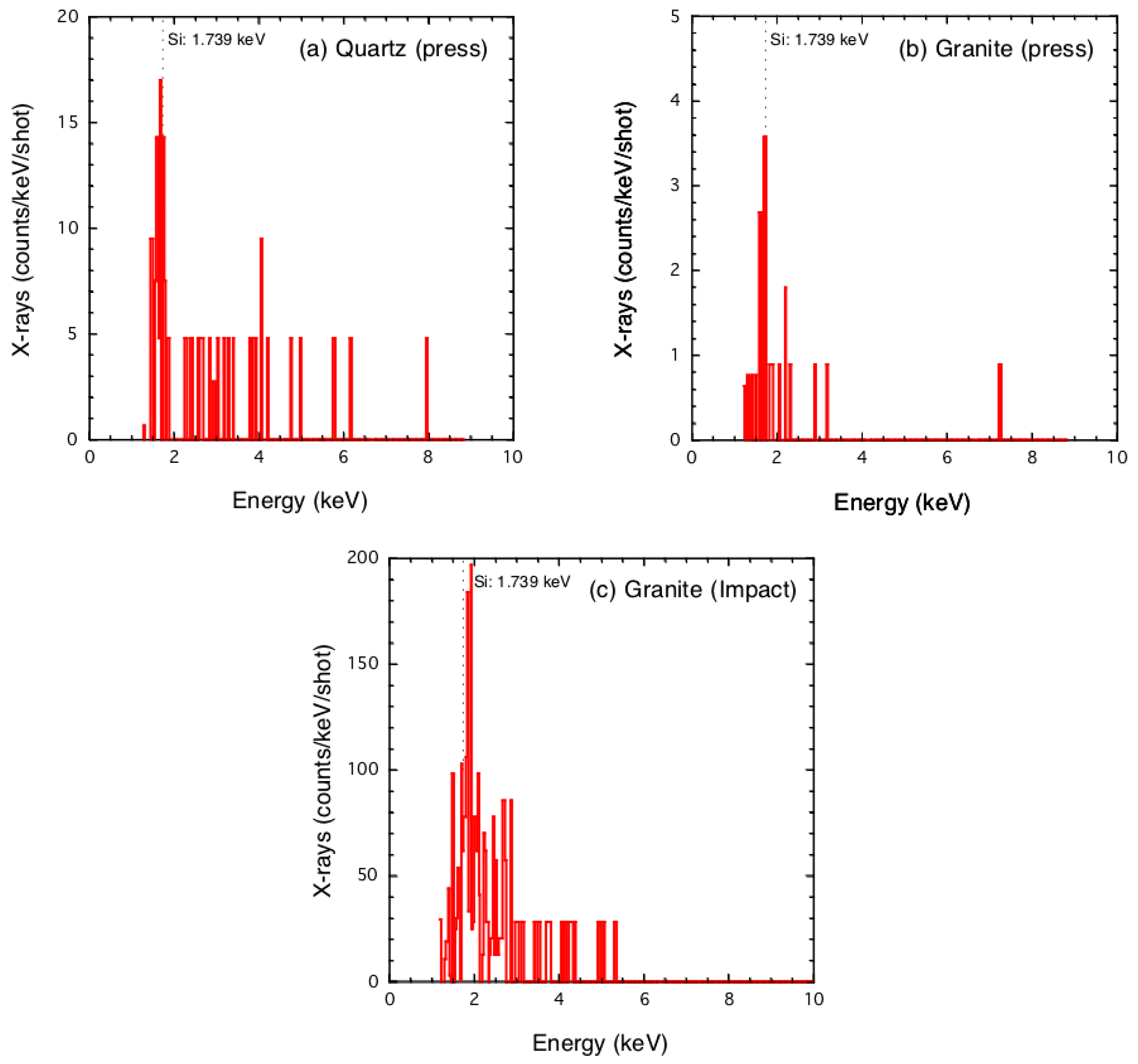
Figure 3 shows the noise-subtracted spectrum of X-ray counts per shot divided by bin-size (0.035 keV) as a function of photon energy for (a) quartz by the press, (b) granite by the press, and (c) granite by impact (the original spectra are shown in Figure S1 in Supplementary Materials). Because the spectra for basalt by both the press and impact experiments show no clear lines (see Figure S1 in Section S1.1 and Figure S2 and Table S1 in Section S1.2 in Supplementary Materials), we exclude these data from the subsequent analysis. The noise subtraction procedure applied to the data is described in Supplementary Materials (Section S1.3). Although some residual counts at energies lower than 1.2 keV are observed after subtraction, these counts should not be X-rays from the sample because Be and polyimide films between the sample and the detector significantly absorb X-rays (transmittance is less than 1%); hence, we do not plot these counts.
For quartz and granite, a peak around the energy of the Si line (1.739 keV) is observed. Based on the spectra shown in Figure 3, we consider the X-ray counts in the energy range of 1.6 to 1.9 keV to correspond to the Si line. Because the resolution of this detector Γ is ~0.2 keV FWHM (full width at half maximum), if the profile of the line is ideally Gaussian, the standard deviation σSi is represented as Γ/(2(2ln2)1/2) = 0.085 keV. Hence, this energy range corresponds to ~2σSi. For press disruption, the counts of the Si line between 1.6 to 1.9 keV for quartz and granite are 54 and 5.7 counts per shot, respectively. Multiplying the energy of bin-size (0.035 keV), the number of photons is obtained to be 1.9 and 0.2 photons per shot, respectively. The counts for impact granite disruption are 580 counts per shot, corresponding to 20.3 photons per shot.
The area of the crack surface that radiated X-rays was not directly measured in the press experiments. Hence, we assume the areas to be the same as those obtained in the visible-light measurements (0.35 cm2 for quartz and 0.13 cm2 for granite; see Section 3.2). In the impact experiments, the targets were significantly disrupted, generating many small fragments even at the sides of the targets [27]. A large number of cracks appeared on the sides of the targets in the field of view of the detector and it was difficult to measure the exposed area of the crack surface. Hence, we substitute the area of the field of view of the detector through the hole on the plate at the side of the target box π (3.25 cm)2 (Figure 2b).
Because the absorption rates of Be and polyimide films placed between the sample and the detector are known as a function of photon energy, the numbers of photons before being absorbed can be obtained. We also correct the shielding effect of the wire-mesh (a factor of 1.56). Furthermore, the number of photons in every direction are evaluated by multiplying 4π over the solid angle of the detector, which is the area of the detector (diameter 5 mm) over the square of the distance between the samples and the detector. Thus, we obtain the following total numbers of X-rays at the energy of the Si line in every direction NpX(Si), (5.6 ± 1.7) × 105 and (8.7 ± 3.5) × 104 photons/cm2 for quartz and granite during press disruption, respectively, and 2.9 × 10⁵ photons/cm2 for granite target during impact disruption. The results for granite are similar for the press and impact methods, and the result for quartz is slightly higher than that for granite. The results are summarized in Table 1.

3.2. Visible Light

Figure 4 shows the typical PM signals during the disruption as a function of time for (a) quartz, (b) granite, and (c) basalt. The images of the samples before fracture and light emission are also shown, with the exception of the basalt sample (no light was recognized by the imaging camera, likely as a result of weak intensity). The duration of emission is less than 1 ms in each case. The PM signals and images in our experiments are summarized in Figures S3−S7 in Supplementary Materials. It should be noted that we also conducted the visible-light measurements with quartz and granite samples placed between polyvinyl chloride (PVC) plates as insulators to check the dependence of the results on the material used to sandwich the sample. The PM signals for quartz and granite samples between PVC plates show that the visible-light emission is the same order as without PVC plates (Figure S8 in Supplementary Materials). Hence, we conclude that the results do not depend on the materials between which the sample is placed and the subsequent evaluation will be based on the results obtained without the insulator plates.
The output of the PM integrated over time is converted into the energy of visible light. Then, the energy in every direction is evaluated by multiplying 4π over the solid angle of the detector, which is the area of the detector (diameter 15 mm) over the square of the distance between the sample and the detector (78 mm). Thus, we obtained the total energy of light in every direction (EV).
The fracture areas are estimated as luminous parts in the images taken by the imaging camera, except in the case of basalt (a luminous area was not recognized, likely because of low intensity). The fracture areas determined are 0.35 cm2 for quartz (average of three shots) and 0.13 cm2 for granite (average of six shots). For basalt, we substitute the average fracture area for granite.
Thus, the total energy Ev in every direction per unit area is (1.5 ± 0.4) × 10−7 J/cm2 (=(9.4 ± 2.7) × 1011 eV/cm2) for quartz (average of three shots), (7.4 ± 2.3) × 10−9 J/cm2 (=(4.6 ± 1.4) × 1010 eV/cm2) for granite (average of six shots), and 4.3 × 10⁻¹⁰ J/cm2 (=2.7 × 10⁹ eV/cm2) for basalt (the result of a single shot). Assuming the wavelength of detected photons λ to be 0.65 μm (the photon energy is hc/λ = 3.1 × 10⁻¹⁹ J, where h and c are Plank constant and the speed of light), the total number of photons in the visible light NpV = EV/(hc/λ) becomes, (4.9 ± 1.4) × 1011 (quartz), (2.4 ± 0.7) × 1010 (granite), and 1.4 × 10⁹ (basalt). These values are summarized in Table 1.

4. Discussion

4.1. Number of Electrons Resulting in X-ray

First, we investigate the efficiency η of X-ray generation at the energy of the Si line from incident electrons, by numerically estimating counts of fluorescence and bremsstrahlung X-ray photons generated by electron collisions with the samples with a model composition of quartz, granite, and basalt using a numerical model for X-ray tubes [28] (see Section S2 in Supplementary Materials). The model composition of the samples is listed in Table S2 [29,30]. We consider 6.25 × 10⁹ electrons with a monochromatic energy of 3, 5, and 10 keV that vertically collide with a flat sample surface and investigate X-ray photons with an emission angle of 0° (vertical to the surface) [31,32]. The numerical results indicate that the counts at the K line for electron energies of 5 and 10 keV should be observed to be comparable or larger than that at the Si line (Tables S3−S5). Because the K (3.3 keV) line is unclear in the experiments as shown in Figure 3, we consider the case that the energy of electrons resulting in the X-ray emission is 3 keV. The numerical calculations for each sample at an electron energy of 3 keV (Tables S3−S5) show the total counts at the Si line in every direction to be 4π × 2.8 × 104 (quartz) and 4π × 2.1 × 104 (granite), respectively. Hence, the efficiency η is obtained by dividing these counts by the number of incident electrons 6.25 × 10⁹ as 5.6 × 10⁻⁵ for quartz and 4.2 × 10⁻⁵ for granite.
Then, the number of electrons NeX that result in the X-rays is estimated to be NpX(Si)/η, where NpX(Si) is the number of the X-rays obtained in the previous section. Thus, NeX is (9.9 ± 2.9) × 109 and (2.1 ± 0.8) × 109 electrons/cm2 for quartz and granite during press disruption, and 6.9 × 10⁹ electrons/cm2 for granite target during impact disruption. We summarize the values in Table 1.

4.2. Comparison between X-ray and Radio Waves

In this section, we evaluate the number of electrons that result in radio waves during rock fracture observed in previous studies [3,6], assuming that the travelling electrons radiate radio waves. Radio waves were observed at distances shorter than the wavelength in the previous experiments [3,5,6,7,8,9]. In such cases, the electromagnetic fields EN and BN radiated from a moving electron at short distances are represented as EN~e/(4πε0r2) and BN~veEN/c2 when the velocity of electrons ve is smaller enough than the speed of light c (ve was evaluated to be ~106 m/s in our case), where e, ε0 and r are the electron charge, the permittivity of free space, and the distance between the antenna and the electrons, respectively [33].
Warwick et al. [3] measured the electric field Eob to be ~6 × 10⁻² V/m at r = 3.3 cm (Figure 3a in Ref. [3]). This electric field corresponds to the number of electrons as expressed by the ratio of the power, (Eob/EN)2~2.1 × 109 electrons. Although the sample size is not explicitly described in Ref. [3], assuming it to be a few centimeters, we obtain the number of electrons per unit area to be ~109 electrons/cm2. From Eob, we estimate the magnetic field that should be observed as veEob/c2 = 3 × 10⁻⁷ G at r = 0.5 cm and ve = 106 m/s. The observed magnetic field was ~10−6 G at r = 0.5 cm (Figure 3b in Ref. [3]), slightly larger than the expected value but consistent within one order of magnitude.
In Ref. [6], the electric field Eob during granite fracture experiments (the cross-sectional area of the granite sample was 6 × 3 = 18 cm2) was represented as 10−14/(4πε0r3), where r was 0.3−1.0 m in the experiment. Hence, (Eob/EN)2 becomes (10−14/er)2~1 × 1010, and the number of electrons per unit area is 5 × 10⁸ electrons/cm2.
Thus, the number of electrons that radiate radio waves is consistent with the number of electrons that result in the emission of X-rays from granite within an order of magnitude; ~109 electrons/cm2.

4.3. Comparison between X-ray and Visible Light

The number of photons in the visible light NpV is several tens of times larger than the number of electrons resulting in the X-rays NeX (Table 1). This implies that one electron collides with several N2 molecule and excites them at least several tens of times. The excitation occurs when electron energy becomes sufficient to excite N2 (e.g., 7.392 eV: ground state to B3Πg), corresponding to the velocity ve~106 m/s. Setting the acceleration a to ~(e/m)(Vc/L)~1017 m s−2, where e, m and Vc/L are the charge of an electron, the mass of an electron, and the electric field between crack surfaces (assuming a constant of 106 V/m, see Section 4.4), respectively, one electron can excite N2 molecules after the flight of ~ve2/a~10 μm in length (note that this length is comparable to the mean free path of electrons for the impact excitation of N2, 1/(ns), where n and s are the number density of N2 (2.4 × 10¹⁹ /cm3 at the atmospheric pressure) and the cross section of N2 excitation by electron impact (several 10−17 cm2 at ~10 eV [34]), respectively). Setting the distance between crack surfaces on the order of millimeters, the maximum number of excitation per one electron is ~(1 mm)/(10 μm) = 100. This is slightly higher than the several tens of collisions obtained from the X-ray and visible-light observations. Nevertheless, this result is qualitatively consistent because the excitation does not always result in the visible-light emission at 0.65 μm (e.g., the cross sections of N2 excitation by electron impact to B3Πg and C3Πu that results in visible and UV-light emissions, respectively, are comparable ~5 × 10⁻¹⁷ cm2 at ~10 eV [34]).
Note that the visible-light emission during basalt fracture was recognized but the X-ray emission was not detected. The number of photons in the visible light emitted during basalt fracture was an order of magnitude smaller than that during granite one. Hence, the numbers of electrons and X-ray photons during basalt fracture would be also an order of magnitude smaller than those during granite one. Thus, the X-ray emission during basalt fracture probably occurred, but the number of the X-ray photons was too small for our measurement system.

4.4. Crack Surface Electrification during Rock Fracture

The surface charge per unit area Q can be evaluated as ε0Vc/L, where Vc and L are the voltage and the distance between opposite crack surfaces, respectively. The X-ray spectrum (Figure 3) shows that no significant lines are observed at high energy (e.g., potassium at 3.3 keV and calcium at 3.7 keV) for granite. This implies that the electron energy is on the order of kiloelectron volts; that is, Vc is on the order of kilovolts. The distance L can be evaluated as tL × vs, where tL is the duration of light emission (an order of 0.1 ms) and vs is the separation speed between crack surfaces, depending on the elastic properties of the samples, which is on the order of ~10 m/s evaluated by the sound velocity of samples (a few km/s) multiplied by the maximum strain of them (~1%) [25]. Hence, L is on the order of millimeters in our experiments, consistent with the luminous area of fracture in our experiments (Figure 4). Thus, Vc/L is ~104 V/cm, and Q becomes 9 × 10⁻¹⁰ C/cm2.
Because frictional processes can occur during the fracture of any material, tribo-electrification is possible in every sample [17]. The typical charge density in tribo-electrification is shown as ~10−10 C/cm2 (a metal bead of ~1 mm diameter [35]), ~10−8 C/cm2 (a nonconductive sphere of 0.2 mm diameter [35]), 9.2 × 10⁻¹⁰ C/cm2 (collisional charging of silica spheres of ~1 μm diameter with a velocity up to 10 m/s [36]), and ~10−9 C/cm2 in the peeling of tape [24], which are comparable to the obtained Q in our experiments. On the other hand, piezo-elastic electrification is also expected during the fracture of quartz and quartz-bearing granite. In this case, the charge density can be evaluated as d × Y, where d and Y are the piezoelectric strain constant and disruption strength, respectively. When quartz inside granite is stressed during the fracture of granite, the charge density becomes ~10−9 C/cm2, using the piezo-electric strain constant d = 2 × 10⁻¹² C/N (for quartz [37]) and the tensile strength as Y~10 MPa (for granite [38]). This is also comparable to the obtained Q. Thus, both electrification processes are possible during rock fracture. Both are effective for quartz and granite, while only tribo-electrification is effective for basalt. This may cause the relatively weak emissions during basalt fracture.
The electric field between crack surfaces (Vc/L~104 V/cm) is so weak that field emission generally cannot occur. Nevertheless, electrons are emitted between crack surfaces. This may be caused by the enhanced local electrostatic potential gradient. The electric field would be extremely uneven and diverge at sharp tips such as those found in fractal structures, even if the average field is weak [39,40]. In fact, it has been shown numerically that a rough surface with fractal structure enhances the electric fields [41]. Crack surfaces are fractal [42] and may enhance the local electric field, resulting in field emission. Moreover, the conditions of the electrons added and trapped on crack surfaces through electrification processes are complex (e.g., its energy level [43]). Such electrons may be easily emitted even when the electric field between opposing surfaces is weak.

4.5. Feasibility of Observing the Radiation Emitted during Rock Fracture

4.5.1. Observation of X-ray Emitted during Rock Fracture in Space

We apply the experimental result to the observation of X-rays emitted during the fracture of natural rocks in space. When a granite with a size of l is disrupted, the number of emitted X-ray is evaluated as ~Npxl2). A detector with an area of S at a distance of R receives Npxl2)S/(4πR2). Setting Npx to 1 × 10⁵ photon/cm2, the number of the X-rays n we can detect becomes,
n   ~ 250 ( l 1   m ) 2 ( S 1   m 2 ) ( R 1   km ) 2
This indicates that in situ observations by future orbiter or rendezvous missions around celestial bodies such as satellites and asteroids may allow us to detect X-rays emitted during the fracture of natural rocks on these bodies. For example, in the case of the impact experiments in space such as Hayabusa2 [44], setting l, S, and R to ~1 m, ~10 cm2, and ~100 m, respectively, n is approximately 20 to 30. On the other hand, it is quite difficult to detect the X-rays around Earth when the disruption occurs on the moon, in the asteroid belt, or at farther places.
Rather than remote-sensing measurements, this phenomenon would be applied to in situ X-ray fluorescence analysis of the composition of rocks on the surface of celestial bodies. Scratching the surface of samples (l~1 mm), the detector (S~1 cm2) at a distance from the samples of R~10 cm can receive X-rays with n of ~2−3. We can obtain enough signals relative to noise by repeatedly scratching the samples. Because sunlight and X-ray sources are not necessary, this instrument will be useful in future explorations.

4.5.2. Observation of Radio Waves in Natural Earthquakes

Here, we evaluate the feasibility of observing radio waves. The power of radio waves in the far field (the distance between the observation point and the fractured part is longer than the wavelength) caused by the electrons traveling between the crack surfaces with an acceleration of a is evaluated as WF = Ne × a2e2/(6πε0c3), where Ne is the number of electrons traveling between crack surfaces per unit area. From our results, setting a and Ne to ~1017 m/s2 and ~109 electrons/cm2 = 1013 electrons/m2, respectively, WF becomes ~10−6 J/s/m2. When we detect this radiation at a MHz band (~106 Hz), this becomes ~10−12 J/s/m2/Hz. In the case of public broadcasting, the power of radio waves from a broadcasting station may be an order of kilowatts and we detect a power of ~10−12 J/s/m2/Hz at a MHz band at a distance of ~10 km from the station. This is comparable with the radiation from the electrons during rock fracture. Thus, the observation of the radio waves may be possible in natural earthquakes, though the more detailed studies on various effects such as the direction and distance from hypocenter and receive frequency would be necessary as a future work.

4.5.3. Observation of Visible Lights in Natural Earthquakes

In recent earthquakes, relatively quantitative estimations of visible light have been reported, e.g., the light at Hyogo-ken Nanbu earthquake in Japan was observed to appear as luminous as the full moon, a luminosity of an order of 0.01 lx [4]. If the light emitted from a fault illuminated the clouds in the sky, where the distance between the ground and the clouds is an order of 100 m, the luminance of the light source was ~0.01 × (4π(100)2)~103 lumen. Dividing by a factor of 1700 to convert the units from lumens to watts, this becomes 103/1700~an order of 1 W. Setting the photon energy and the duration of the light to be 3 × 10⁻¹⁹ J and 1 s [4], respectively, the total number of emitted photons was ~1018 photons. The exposed surface area of the fault on the ground is estimated from the length scale of the fault in this earthquake of 3 km [4] and the depth of exposed parts assumed to be 1 m that is a typical offset of faults [45], as 3 km × 1 m~3 × 107 cm2. Thus, the total number of photons per unit area (1018 photons)/(3 × 107 cm2) becomes an order of 1010 photon/cm2. This is consistent with our experimental results Npv within one order of magnitude. Therefore, the visible light observed during this earthquake was likely caused by the radiation during rock fracture. Thus, the radiation during rock fracture may be observable in natural earthquakes, though, again, various effects such as the depth of hypocenters should be considered in detail as a future work.

5. Conclusions

We experimentally measured X-ray and visible-light emissions during the fracture of quartz, granite, and basalt. The number of electrons that result in the X-ray NeX is evaluated and compared with the number of photons in visible light NpV. The ratio NpV/NeX falling between 10 and 50 implies that one electron collides and excites N2 molecules at least several tens of times during its flight. This number of collisions resulting in visible-light emission is slightly less than the expected upper limit ~100. This is reasonable because the collision does not only cause the visible-light emission but also UV-light emission. Furthermore, NeX is comparable with the number of electrons that result in the emission of radio waves during the fracture of quartz-bearing rocks in previous studies. Thus, we conclude that the X-ray radiation actually occurs during rock and mineral fracture and that the radiations during rock and mineral fracture can be attributed to the flight of electrons between fracture surfaces (the X-rays during basalt fracture was not detected, but the X-ray emission would occur because the visible light was emitted during the fracture). Finally, we discuss the feasibility of observing the X-ray emission in planetary exploration and the radio waves and the visible light during natural earthquakes. The X-rays can be detected in space and also the radio waves and the visible light are observable during earthquakes.

Supplementary Materials

The following supporting information can be downloaded at: https://www.mdpi.com/article/10.3390/min12060778/s1. Figure S1: X-ray counts (the original data including noise) per bin size (0.035 keV) per shot obtained by the press and impact experiments: (a) quartz by the press (the number of shots was 6), (b) granite by the press (32 shots), (c) basalt by the press (20 shots), (d) blank test in the press experiment (19 shots), (e) granite by the impact (1 shot), (f) basalt by the impact (1 shot), and (g) blind shot in the impact experiment (1 shot). Figure S2: Procedure for the evaluation whether the peak around 1.74 keV is the Si line or noise. Figure S3: Photomultiplier output for quartz. The result named quartz 005 is the same as Figure 4a. The light was too intense in quartz 004 and the peak voltage was not be obtained. Figure S4: Quartz sample images before fracture (upper line) and the light emission during fracture (lower line). Number 005 is the same as the images in Figure 4a. The horizontal white bar in each figure of the original sample indicates 1 cm. Figure S5: Photomultiplier output for granite. The result of granite 009 is the same as Figure 4b. Figure S6: Granite sample images before fracture (left-end in each line) and the light emission during fracture (denoted by the number). Number 009 is the same as the image in Figure 4b. The horizontal white scale bar indicates 1 cm in each image before fracture. When the samples emitted the light, sometimes they were partially (not completely) broken. In this case, we continued to press the samples until next emission. For the sample shown in the third line, we observed the light emissions three times (014, 015 and 017). Figure S7: Photomultiplier output for basalt (the same as Figure 4c). No image was obtained by the camera. Figure S8: Photomultiplier output for quartz and granite placed between polyvinyl chloride plates. Table S1: Comparison between peak counts and noise. Table S2: A model composition of the samples in mass fraction. Table S3: Quartz: The calculation result of fluorescence and bremsstrahlung X-ray photon counts per steradian from quartz at an emission angle of 0, when 6.25 × 10⁹ electrons perpendicularly irradiate target surface. Table S4: Granite: The calculation result of fluorescence and bremsstrahlung X-ray photon counts per steradian from granite. Table S5: Basalt: The calculation result of fluorescence and bremsstrahlung X-ray photon counts per steradian from basalt (diabase).

Author Contributions

T.K., K.O., K.S., M.A., K.K., T.O., T.M., S.H., A.I.S. and H.K. conducted the experiments and contributed to data preparation, interpretation of results, and writing of the manuscript. K.O. performed the numerical simulations. T.K. designed the article and completed the manuscript. All authors have read and agreed to the published version of the manuscript.

Funding

This research was funded by JSPS KAKENHI, grant number JP20340128, JP24540538, and JP17K18812.

Data Availability Statement

The datasets used and/or analyzed during the current study are available from the corresponding author on reasonable request.

Acknowledgments

The authors thank A. Fujiwara for fruitful discussions at the first stage of this study, T. G. Tsuru, A. M. Nakamura, T. Tanigawa, R. Suetsugu, S. Sugita and H. Mizutani for useful comments and stimulating discussions, M. Yasui, Y. Shimaki, T. Okada, K. Ishiyama, H. Togami and K. Ohno for supporting the experiments, M. Koga for creating the figures and supporting the data analysis, C. P. Carman for checking the English usage, and T. Sakaiya and the diagnostic group of Gekko XII laser facility for supporting the experiments at preliminary stages. This work was supported by ISAS/JAXA as a collaborative program with the Hypervelocity Impact Facility.

Conflicts of Interest

The authors declare no conflict of interest.

References

  1. Terada, T. On luminous phenomena accompanying earthquakes. Bull. Earthq. Res. Inst. Tokyo Imperial Univ. 1931, 9, 225–255. [Google Scholar] [CrossRef]
  2. Derr, J.S. Earthquake lights: A review of observations and present theories. Bull. Seismol. Soc. Am. 1973, 63, 2177–2187. [Google Scholar]
  3. Warwick, J.W.; Stoker, C.; Meyer, T.R. Radio emission associated with rock fracture: Possible application to the Great Chilean Earthquake of May 22, 1960. J. Geophys. Res. 1982, 87, 2851–2859. [Google Scholar] [CrossRef]
  4. Tsukuda, T. Sizes and some features of luminous sources associated with the 1995 Hygo-ken Nanbu earthquake. J. Phys. Earth 1997, 45, 73–82. [Google Scholar] [CrossRef]
  5. Nitsan, U. Electromagnetic emission accompanying fracture of quartz-bearing rocks. Geophys. Res. Lett. 1977, 4, 333–336. [Google Scholar] [CrossRef]
  6. Ogawa, T.; Oike, K.; Miura, T. Electromagnetic radiations from rocks. J. Geophys. Res. 1985, 90, 6245–6249. [Google Scholar] [CrossRef]
  7. Cress, G.O.; Brady, B.T.; Rowell, G.A. Sources of electromagnetic radiation from fracture of rock samples in the laboratory. Geophys. Res. Lett. 1987, 14, 331. [Google Scholar] [CrossRef]
  8. Yamada, I.; Masuda, K.; Mizutani, H. Electromagnetic and acoustic emission associated with rock fracture. Phys. Earth Planet. Inter. 1989, 57, 157–168. [Google Scholar] [CrossRef]
  9. Martelli, G.; Smith, P.N.; Woodward, A.J. Light, radiofrequency emission and ionization effects associated with rock fracture. Geophys. J. Int. 1989, 98, 397–401. [Google Scholar] [CrossRef] [Green Version]
  10. Brady, B.T.; Rowell, G.A. Laboratory investigation of the electrodynamics of rock fracture. Nature 1986, 321, 488–492. [Google Scholar] [CrossRef]
  11. Kawaguchi, Y. Charged particle emission and luminescence upon bending fracture of Granite. Jpn. J. Appl. Phys. 1998, 37, 3495–3499. [Google Scholar] [CrossRef]
  12. Kato, M.; Mitsui, Y.; Yanagidani, T. Photographic evidence of luminescence during faulting in granite. Earth Planets Space 2010, 62, 489–493. [Google Scholar] [CrossRef] [Green Version]
  13. Dickinson, J.T. Fracto-emission. In Non-Destructive Testing of Fibre-Reinforced Plastics Composites, Vol. 2; Summerscales, J., Ed.; Springer: New York, NY, USA, 1990; pp. 429–482. [Google Scholar]
  14. Klyuev, V.A.; Toporov, Y.P.; Allev, A.D.; Chalykh, A.E.; Lipson, A.G. The effect of air pressure on the parameters of x-ray emission accompanying adhesive and cohesive breaking of solids. Sov. Phys. Tech. Phys. 1989, 34, 361–364. [Google Scholar]
  15. Finkelstein, D.; Powell, J. Earthquake Lightning. Nature 1970, 228, 759–760. [Google Scholar] [CrossRef] [PubMed]
  16. Mizutani, H.; Ishido, T.; Yokokura, T.; Ohnishi, S. Electrokinetic phenomena associated with earthquake. Geophys. Res. Lett. 1976, 3, 365–368. [Google Scholar] [CrossRef]
  17. Walton, A.J. Triboluminescence. Adv. Phys. 1977, 26, 887–948. [Google Scholar] [CrossRef]
  18. Chandra, B.P. Mechanoluminescence. In Luminescence of Solids; Vij, D.R., Ed.; Plenum Press: New York, NY, USA, 1998; pp. 361–389. [Google Scholar]
  19. Xie, Y.; Li, Z. Triboluminescence: Recalling interest and new aspects. Chem 2018, 4, 943–971. [Google Scholar] [CrossRef] [Green Version]
  20. Chandra, B.P.; Chandra, V.K.; Jha, P.; Patel, R.; Shende, S.K.; Thaker, S.; Baghel, R.N. Fracto-mechanoluminescence and mechanics of fracture of solids. J. Lumin. 2012, 132, 2012–2022. [Google Scholar] [CrossRef]
  21. Harvey, E.N. The luminescence of adhesive tape. Science 1939, 89, 460–461. [Google Scholar] [CrossRef] [Green Version]
  22. Dickinson, J.T.; Park, M.K.; Donaldson, E.E.; Jensen, L.C. Fracto-emission accompanying adhesive failure. J. Vac. Sci. Technol. 1982, 20, 436–439. [Google Scholar] [CrossRef] [Green Version]
  23. Berkov, V.I.; Lipson, A.G.; Klyuev, V.A.; Toporov, Y.P.; Deryagin, B.V. Mechanism for x-ray emission during breaking of adhesion bonds. Sov. Phys. Dokl. 1987, 32, 381. [Google Scholar]
  24. Camera, C.G.; Escobar, J.V.; Hird, J.R.; Putterman, S.J. Correlation between nanosecond X-ray flashes and stick-slip friction in peeling tape. Nature 2008, 455, 1089–1092. [Google Scholar] [CrossRef]
  25. Kadono, T.; Arakawa, M.; Mitani, N.K. Fragment velocity distribution in the impact disruption of thin glass plates. Phys. Rev. E 2005, 72, 045106. [Google Scholar] [CrossRef] [PubMed] [Green Version]
  26. Kurosawa, K.; Nagaoka, Y.; Senshu, H.; Wada, K.; Hasegawa, S.; Sugita, S.; Matsui, T. Dynamics of hypervelocity jetting during oblique impacts of spherical projectiles investigated via ultrafast imaging. J. Geophys. Res. 2015, 120, 1237–1251. [Google Scholar] [CrossRef] [Green Version]
  27. Kadono, T.; Tanigawa, T.; Kurosawa, K.; Okamoto, T.; Matsui, T.; Mizutani, H. Correlation between fragment shape and mass distributions in impact disruption. Icarus 2018, 309, 260–264. [Google Scholar] [CrossRef]
  28. Ebel, H. X-ray tube spectra. X-ray Spectrom. 1999, 28, 255–266. [Google Scholar] [CrossRef]
  29. Mason, B.; Moore, C.B. Principles of Geochemistry, 4th ed.; John and Wiley & Sons: New York, NY, USA, 1982. [Google Scholar]
  30. Li, Y.-H. Distribution patterns of the elements in the ocean: A synthesis. Geochim. Cosmochim. Acta 1999, 55, 3223–3240. [Google Scholar]
  31. Ogawa, K.; Okada, T.; Shirai, K.; Kato, M. Numerical estimation of lunar X-ray emission for X-ray spectrometer onboard SELENE. Earth Planets Space 2008, 60, 283–292. [Google Scholar] [CrossRef] [Green Version]
  32. Ogawa, K. Basic Development of a Compact X-ray Tube for In-Situ X-ray Analysis of Planetary Surface Composition. Ph.D. Thesis, Tokyo Institute of Technology, Tokyo, Japan, 2008. [Google Scholar]
  33. Landau, L.D.; Lifshitz, E.M. The Classical Theory of Fields; Pergamon: Oxford, UK, 1971. [Google Scholar]
  34. Borst, W.L. Excitation of several important metastable states of N2 by electron impact. Phys. Rev. A 1972, 5, 648656. [Google Scholar]
  35. McCarty, L.S.; Whitesides, G.M. Electrostatic charging due to separation of ions at interfaces: Contact electrification of ionic electrets. Angew. Chem. Int. Ed. 2008, 47, 2188–2207. [Google Scholar] [CrossRef]
  36. Poppe, T.; Blum, J.; Henning, T. Experiments on collisional grain charging of micron-sized preplanetary dust. Astrophys. J. 2000, 533, 472–480. [Google Scholar] [CrossRef]
  37. National Astronomical Observatory of Japan (Ed.) Chronological Scientific Tables; Maruzen: Tokyo, Japan, 2016. [Google Scholar]
  38. Lockner, D.A. Rock failure. In Rock Physics and Phase Relations: A Handbook of Physical Constants, AGU Reference Shelf 3; Ahrens, T.J., Ed.; American Geophysical Union: Washington, DC, USA, 1995; pp. 128–148. [Google Scholar]
  39. Mandelbrot, B.B.; Evertsz, C.J.G. The potential distribution around growing fractal clusters. Nature 1990, 348, 143–145. [Google Scholar] [CrossRef]
  40. Family, F.; Vicsek, T. Simulating fractal aggregation. Comput. Phys. 1990, 4, 44–49. [Google Scholar] [CrossRef]
  41. De Assis, T.A.; Borondo, F.; Benito, R.M.; Andrade, R.F.S. Field emission properties of fractal surfaces. Phys. Rev. B 2008, 78, 235427. [Google Scholar] [CrossRef] [Green Version]
  42. Feder, J. Fractals; Plenum: New York, NY, USA, 1988. [Google Scholar]
  43. Kittel, C. Introduction to Solid State Physics, 8th ed.; John Wiley & Sons: New Jersey, NJ, USA, 2005. [Google Scholar]
  44. Arakawa, M.; Saiki, T.; Wada, K.; Ogawa, K.; Kadono, T.; Shirai, K.; Sawada, H.; Miura, A. An artificial impact on the asteroid (162173) Ryugu formed a crater in the gravity-dominated regime. Science 2020, 368, 67–71. [Google Scholar] [CrossRef] [PubMed]
  45. Hirata, T. Fractal dimension of fault systems in Japan: Fractal structure in rock fracture geometry at various scales. Pure Appl. Geophys. 1989, 131, 157–170. [Google Scholar] [CrossRef]
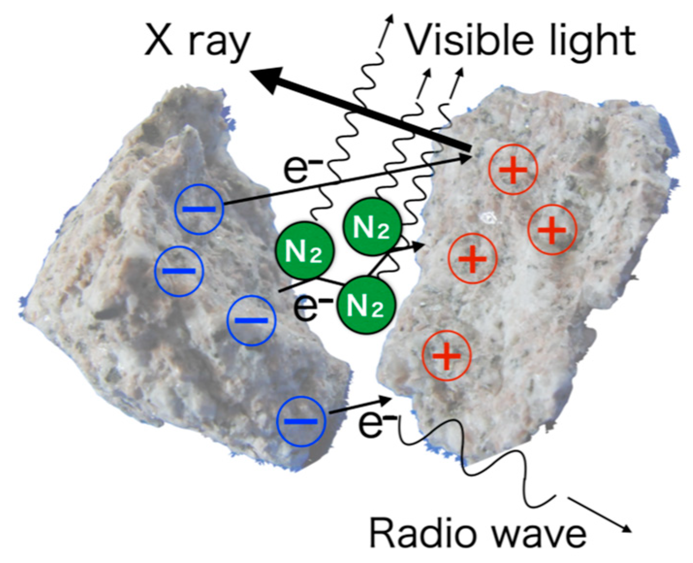
Figure 1. Schematic view of the process in the radiation during rock fracture.
Minerals 12 00778 g001
Figure 2. The experimental configurations: (a) press and (b) impact experiments for X-ray measurements, and (c) press experiment in the atmosphere for visible-light measurements.
Minerals 12 00778 g002
Figure 3. X-ray spectra: (a) quartz by press, (b) granite by press, and (c) granite by impact. The horizontal axis is photon energy and the vertical axis is the photon counts per shot divided by the bin-size of 0.035 keV.
Minerals 12 00778 g003
Figure 4. The photomultiplier output. (a) quartz, (b) granite, and (c) basalt. The horizontal axis is time. The images on the right-side of each output show the sample before the fracture (upper) and the image of bright light emission (lower) taken by the imaging camera. The bright light in the lower image for granite is indicated by an arrow. In the basalt case, the light was not recognized by the camera.
Minerals 12 00778 g004
Table 1. Numbers of the X-rays at Si line per unit area NpX(Si) (photon/cm2), number of electrons resulting in X-rays per unit area NeX (electron/cm2), total energy of photons in the visible light per unit area EV (eV/cm2), and number of photons in visible light per unit area NpV (photon/cm2).
SamplesNpX(Si)NeXEVNpV
Quartz
Press(5.6 ± 1.7) × 105(9.9 ± 2.9) × 109(9.4 ± 2.7) × 1011(4.9 ± 1.4) × 1011
Granite
Press(8.7 ± 3.5) × 104(2.1 ± 0.8) × 109(4.6 ± 1.4) × 1010(2.4 ± 0.7) × 1010
Impact2.9 × 1056.9 × 109No data-
Basalt
Pressundetected-2.7 × 1091.4 × 109
Publisher’s Note: MDPI stays neutral with regard to jurisdictional claims in published maps and institutional affiliations.