Article

Integrated Collaborative Control of “Shielding-Filling-Grouting” of 1 km Deep Large-Section Roadways: A Case Study

1
State Key Laboratory of Coal Resources and Safe Mining, China University of Mining and Technology, Xuzhou 221116, China
2
School of Mines, China University of Mining and Technology, Xuzhou 221116, China
3
Guqiao Coal Mine, Huainan Mining Industry (Group) Co., Ltd., Huainan 232150, China
4
Kouzidong Coal Mine, China Coal Xinji Energy Co., Ltd., Fuyang 236008, China
*
Author to whom correspondence should be addressed.
Minerals 2022, 12(7), 854; https://doi.org/10.3390/min12070854
Submission received: 8 June 2022 / Revised: 28 June 2022 / Accepted: 30 June 2022 / Published: 4 July 2022
(This article belongs to the Special Issue Failure Characteristics of Deep Rocks)

Abstract

:
Effective control of deformation failure of surrounding rock in deep roadway has become an important prerequisite for the safe and efficient development of deep coal resources. In this study, the field measurement of the study area’s in-situ stress was carried out for the specific engineering geological conditions of the KCM −967 m level west-wing main track roadway. The west-wing main track roadway’s full-section deformation failure features were summarized and analyzed, and the main roadway’s surrounding rock nonlinear deformation failure mechanism was revealed from the perspective of elastoplastic mechanics. Based on that, a set of highly targeted integrated collaborative control technology of “shielding-filling-grouting” system was proposed. The industrial field test revealed that, after the above integrated collaborative control scheme was adopted, there was no strong deformation failure on the surface of the main roadway surrounding rock and deep rock mass, which played the role of active and passive support collaborative control, reduced the subsequent repeated repair and maintenance workload of the roadway, and satisfied the needs of long-term safe and efficient production of the mine. The results obtained provide a reference for the control of surrounding rock of deep and large-section roadways in other mining areas.

1. Introduction

A gradual exhaustion of shallow coal resources worldwide resulted in the growing number of kilometer-deep coal mines [1], including over sixty such mines in China [2]. Noteworthy is that the depth of newly excavated roadways increases at a rate of 8~12 m per year [3]. The typical “high in-situ stress, high geothermal, high karst water pressure, and strong mining disturbance” occurrence environment of deep coal rock leads to a series of problems, such as frequent roof fall accidents of deep roadway, significant deformation failure of roadway walls, common roadway floor heave, and severe damage of roadway support components [4,5,6]. One of the conditions for ensuring the safety and continuity of production is to maintain the cross-section of the excavation, which is closely related to the deformation conditions of surrounding rocks [7]. Therefore, effective control of deformation failure of surrounding rocks in deep roadways has become an important prerequisite for safe and efficient development of deep coal resources.
Compared to medium- and shallow-depth roadways, in-situ stresses of deep-depth ones continuously grow, and the soft rock characteristics of coal rock become increasingly significant under the action of high stresses [8,9]. For instance, the maximum principal stress of some kilometer-deep mines can reach more than 40 MPa, significantly exceeding most of the coal rock uniaxial compressive strength in coal measure strata, resulting in serious deformation failure of roadway surrounding rock [10,11,12]. In addition to the high stress effect, the deep roadway surrounding rock stress field will be further redistributed under the action of geological structure and mining-induced stress, resulting in discrete stress degradation and stress concentration. Currently, scholars have studied the ultra-high strength bolt, the grouting modified material, and its mechanical performance applied to the control of surrounding rocks in deep roadways [13,14,15,16,17]. The support-modification-pressure relief collaborative control method of deep roadways and the modification technology of high-pressure splitting grouting of deep roadways were put forward from the technical point of view [18,19]. The deformation failure mechanism of roadways with high stresses and large mining depth was analyzed [20]. The above studies enriched the research results of deformation control of surrounding rock in deep roadways. However, due to the complex geological conditions of deep roadways, the technology and method of deformation control of surrounding rocks in deep roadways still need to be explored.
The Kouzidong Coal Mine (KCM) in the city of Fuyang, China, is a typical 1 km deep mine, which is located in the west of the Huainan Coalfield, with the mine’s first production level elevation of −967 m. As a key point, the roadway in the KCM, namely, the west-wing main track roadway, is responsible for important production auxiliary tasks of the whole mine. Nevertheless, the main roadway of the west-wing track has a large depth, the stress environment of surrounding rock in the roadway is complicated, surrounding rock exhibits poor physical and mechanical properties, and the roadway shows typical features of large deformation, strong rheology, and sudden change after excavation. As a result, some areas were exposed to severe deformation failures, thus affecting operation of the roadway and mining safety. In this study, the KCM west-wing main track roadway was taken as the engineering background. Field measurements of the in-situ stress in the study area were carried out, and the difficulties in control of the surrounding rock in the 1 km deep roadway were analyzed. Based on the original support scheme of the west-wing main track roadway, the main roadway’s surrounding rock full-section deformation failure features and mechanical mechanism were revealed. Given this, a 1 km deep, large-section roadway “shielding-filling-grouting” integrated collaborative control technology system was put forward. The industrial field tests were carried out. The proposed technology system enhanced the effect of control of the surrounding rock in the roadway, and satisfied the practical needs of safe and efficient mining production. The relevant research results can provide a reference for other similar deformation control of the surrounding rock in deep roadways.

2. In-Situ Stress Measurement of West-Wing Main Track Roadway and Difficulty in the Surrounding Rock Control in Roadways

2.1. Engineering Background of the Main Roadway in the West-Wing Track

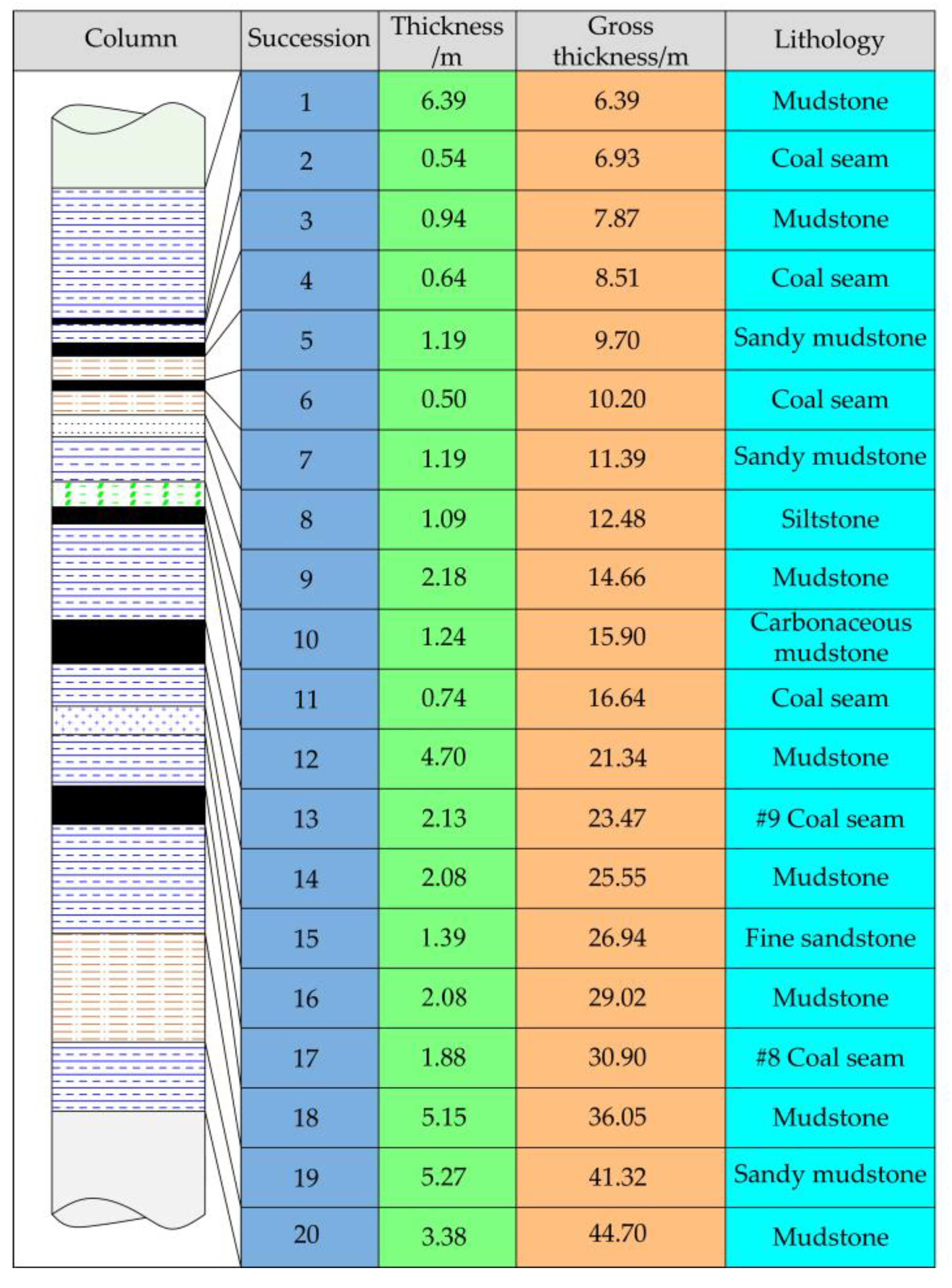
2.1.1. Stratigraphic Characteristics of the Study Area

The main roadway of the west-wing track of the KCM had a depth of −950 m, being adjacent to the main roadway of the west-side belt conveyor haulage in the north, the tail joint roadway of the west-wing main track roadway in the west, and the Fufeng fault in the south. Fine sandstone, quartz sandstone, siltstone, mottled mudstone, mudstone, coal, carbonaceous mudstone, and other coal rock strata were exposed during roadway excavation. The roadway of the study area was excavated in the roof of the #8 coal seam and the roadway surrounding is mainly composed of mudstone and fine sandstone. The comprehensive lithology column of the study area stratum is shown in Figure 1.

2.1.2. Original Support Scheme of the Main Roadway

The section of the main roadway of the west-wing track is a semi-circular arch with an inclined wall, and the combined support of “bolt mesh cable shotcrete” (see Figure 2) is adopted. The main technical parameters are as follows:
(1)
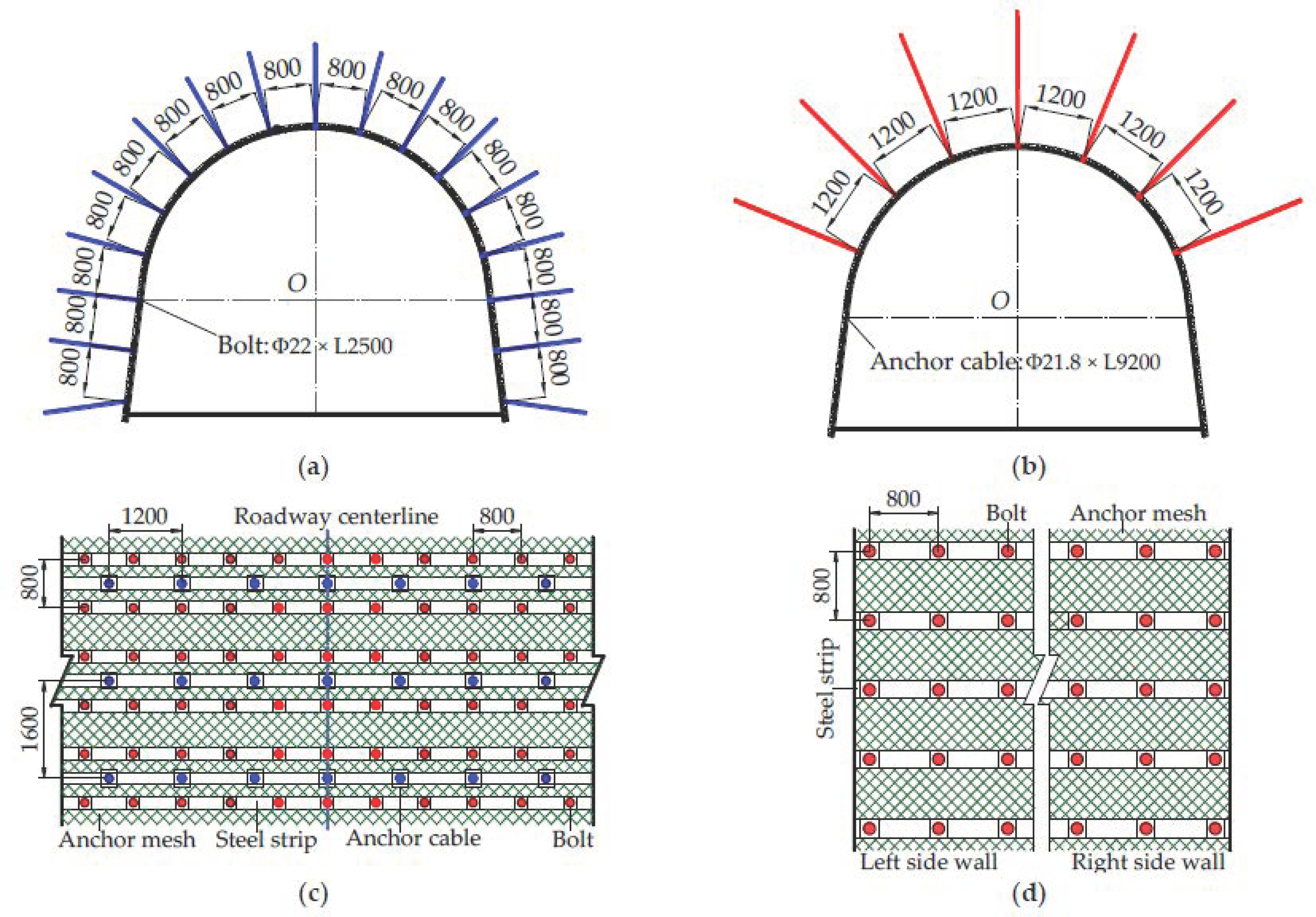
Roof support: Eleven bolts and seven anchor cables are symmetrically arranged in each row of the main roadway roof; the row spacing between bolts is 800 × 800 mm, the size is Φ22 × L2500 mm, the material is high-strength rebar; the row spacing between anchor cables is 1200 × 1600 mm, the size is Φ21.8 × L9200 mm, the material is steel strand; the steel strip is H-shaped steel strip welded with Φ12 mm round steel; the anchor mesh is made by reinforcement mesh, with specification Φ6 × 1000 × 2000 mm; the strength grade of shotcrete is C20, and the initial shotcrete thickness is 30~50 mm.
(2)
Wall support: The two walls of the main roadway are symmetrically arranged with six bolts in each row, while other support parameters are the same as the roof support.
(3)
Floor support: No reinforcement measures are taken for the floor of the main roadway.

2.2. In-Situ Stress Field Measurement and Difficulties in the Roadway Surrounding Rock Control

In-situ stress is one of the root causes of rock mass deformation failure in underground engineering. In-situ stress measurement is an effective method to determine and evaluate the state of underground coal rock stress, providing basic parameters and theoretical basis for scientific design and decision-making of underground engineering [21,22,23,24]. Therefore, to handle the stress field distribution of the KCM −967m level, the field measurements of in-situ stresses in the area near the −967 m level west-wing main track roadway (G1, G2, and G3 stations, respectively) [25] were conducted considering the specific construction conditions of the underground site comprehensively. The specific measurement method was the hollow inclusion stress relief method, and the measuring instrument was a KX-81 hollow inclusion triaxial in-situ stress meter developed by the Institute of Geomechanics, Chinese Academy of Geological Sciences. Table 1 lists in-situ stress specific measurement results, while Figure 3 shows azimuths of horizontal principal stress at different stations. Herein, σ1, σ2, and σ3 are the maximal, medium, and minimum principal stresses, respectively; α is the dip angle; σHmax and σHmin are the maximum and minimum horizontal principal stresses, respectively; σV is the vertical principal stress; β and γ are the maximum and minimum horizontal principal stress azimuths, respectively; k1 is the ratio of the maximum horizontal principal stress to the vertical principal stress; k2 is the maximum-to-minimum horizontal principal stress ratio.
According to the results of on-site in-situ stress measurement, the KCM −967 m level stress field distribution had the following features:
(1)
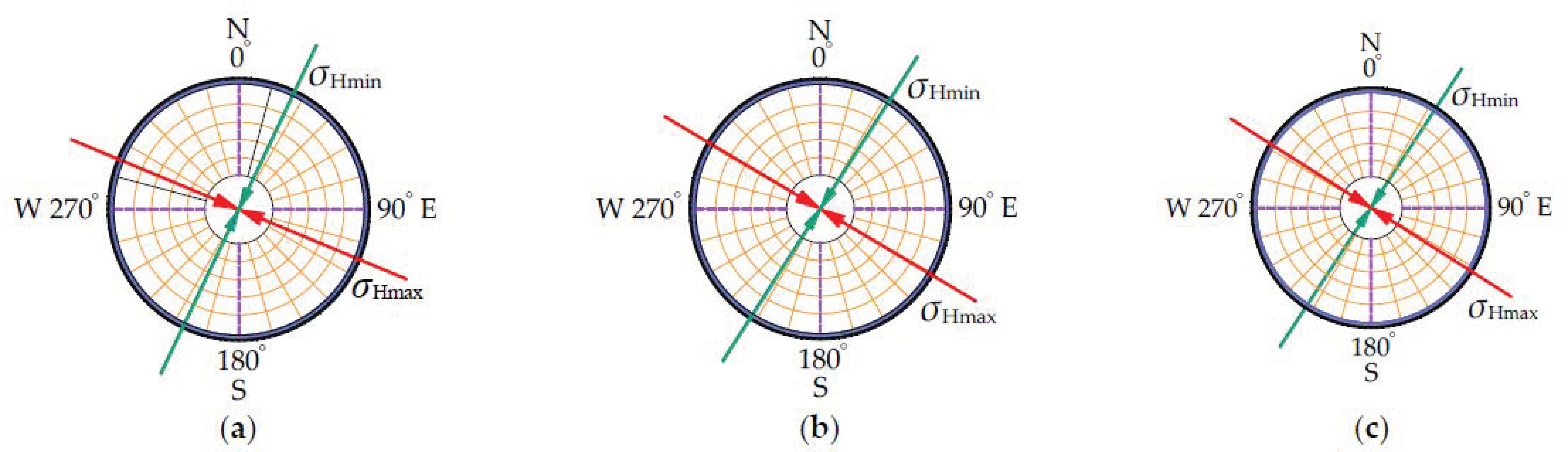
Maximum and minimum depths of the three stations for monitoring of in-situ stress were 960.50 and 958.30 m, respectively, belonging to a typical 1 km deep environment. This implied that the coal rock was in high stress state. The maximum principal stresses of all three stations exceeded 30 MPa (up to 36.10 MPa) and their dip angles of maximum principal stress were below 10°. Additionally, dip angles of medium and minimum principal stresses varied widely, suggesting that the primary rock stress field of the study area was mainly structural stress in the approximately horizontal direction.
(2)
After the coordinate system transformation, the maximum horizontal principal stresses in all three stations exceeded 30 MPa (30.15~37.27 MPa), with the azimuth angles ranging between N 112.54° E~N 122.29° E; the minimum horizontal principal stresses ranged from 14.04 to 21.05 MPa, with the azimuth angles between N 25.43° E~N 33.28° E; the vertical principal stresses ranged from 21.40 to 27.60 MPa.
(3)
The maximum horizontal principal stresses of all three stations were larger than their corresponding vertical principal stresses. The respective ratio k1 ranged from 1.09 to 1.53, demonstrating that the paleotectonic interaction in the study area was relatively strong; the measured maximum-to-minimum horizontal principal stress ratio k2 ranged from 1.43 to 2.28, demonstrating that the in-situ stress in this area had obvious orientation.
In summary, the in-situ stress born by the KCM −967 m level roadway surrounding rock showed typical horizontal structural stress features. In particular, the maximum horizontal principal stress was as high as 37.27 MPa, which significantly exceeded the uniaxial compressive strength of the coal rock in this area, greatly reducing the self-bearing capacity of roadway surrounding rock and seriously affecting the original support effect during the roadway excavation. Besides the dynamic pressure effect, the high-stress roadway surrounding rock nonlinear deformation failure would be more severe, promoting the original support failure. Therefore, it was expedient to carry out the effective integrated reinforcement control of roadway surrounding rock on the basis of original support, in order to improve the guaranteed capacity of safe and efficient production of the mine.

3. Analysis of the West-Wing Main Track Roadway Surrounding Rock Deformation Failure Pattern and Mechanism

3.1. Main Roadway Surrounding Rock Full-Section Deformation Failure Pattern

When the original support scheme was adopted for the −967 m level west-wing main track roadway, the roadway surrounding rock presented the following full-section nonlinear deformation failure features, as shown in Figure 4:
(1)
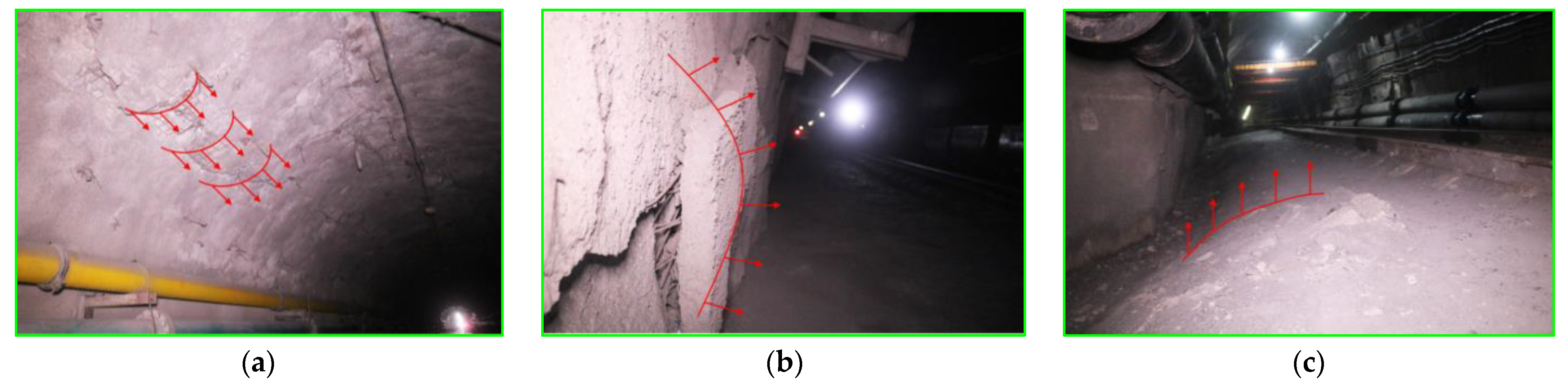
The roadway roof surrounding rock was cracked and separated, and the damage zone extended continuously along the central axis of the main roadway, accompanied by signs of bending and sinking. The shallow bolt (anchor cable) of roof had obvious bending dislocation. Therefore, deformation of shallow surrounding rock was greater than that of deep surrounding rock.
(2)
The two walls of the roadway were damaged, and the surrounding rock was obviously broken unevenly and bulged into the roadway, especially in the corner. Deformation with dominating shear expansion failures also occurred in the side profile; the shotcrete layer of the inclined wall section in some areas peeled off obviously. The metal mesh was exposed, with bending and breaking tendency, while the bolt (anchor cable) at the side profile was also deformed.
(3)
The roadway floor deformation lasted for a long time and had poor structural integrity. The breakthrough gap for strain energy could be easily filled, increasing the loose range of the floor-surrounding rock, with a serious floor heave in some sections.

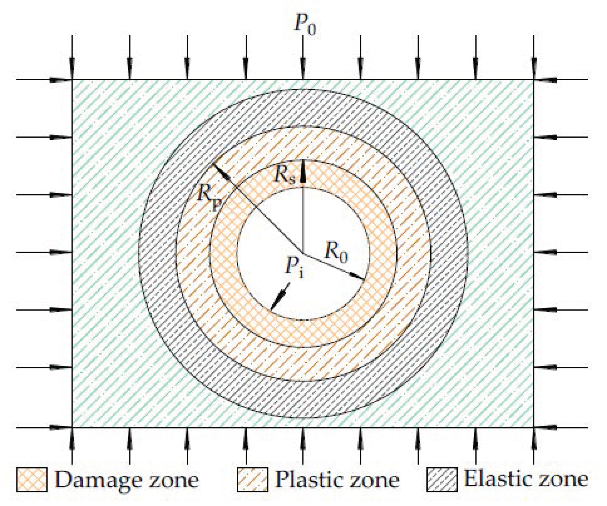
3.2. Mechanism of Nonlinear Deformation Failure of Surrounding Rock in Main Roadway

Excavation of the main roadway would inevitably violate the primary stress equilibrium and stable state of the rock mass. Therefore, the internal stress state of the rock surrounding the roof and the two walls would be redistributed. The gravity-induced stresses would transfer to the deep rock strata of the two walls, and the horizontal stresses would transfer to the deep rock strata of the roof. After exceeding the stress limits of the rocks surrounding the roof and the two walls, the integrity of the main roadway surrounding rock would be violated, and irregular cracks would appear. Meanwhile, the main roadway surrounding rock’s mechanical performance gradually transformed from shallow brittleness to deep plasticity, with strong non-linear, non-smooth plastic deformation and rapid convergence of deformation, and the bearing capacity of surrounding rock is greatly reduced [26,27]. The −967 m level west-wing main track roadway had large depth, high in-situ stress, and poor physical and mechanical properties. The structural distribution in such roadway surrounding rock comprised elastic, plastic, and damage zones [28,29], as shown in Figure 5.
The inelastic (damage and plastic) zones can be described as in [30,31]:
R p = R 0 t * 2 ε * + 1 ( P 0 + σ c + β B 0 ε * 1 ) t * ε * 1 2 ( σ c σ c * + β B 0 ) ε * 2 1 P i + σ c * ε * 1 1 ε * 1
R s = t * R p
where t * = β B 0 / ( σ c σ c * + β B 0 ) 1 / 2 ; B 0 = 1 + μ ε * 1 P 0 + σ c / ε * + 1 ; ε * = 1 + sin φ / ( 1 sin φ ) , Rp is the plastic zone radius, m; Rs is the damage zone radius, m; R0 is the roadway’s theoretical radius, m; P0 is the primary rock stress, MPa; σc is the rock uniaxial compressive strength, MPa; β is brittleness coefficient; σc* is the uniaxial compression residual strength of the rock, MPa; φ is the internal friction angle, °; Pi is the support stress, MPa; μ is Poisson’s ratio.
According to Equations (1) and (2), the main roadway surrounding rock plastic zone radius Rp and the damage zone radius Rs are positively correlated with the theoretical radius of the roadway R0 and the primary rock stress P0, being negatively correlated with the support stress Pi. Thus, the structural distribution of the main roadway surrounding rock can be related to the original physical and mechanical properties of the rock mass, stress environment, and support mode.

4. The “Shielding-Filling-Grouting” Integrated Collaborative Control Technology System for the West-Wing Main Track Roadway

According to the elastoplastic analysis results of Section 3.2, the main causes of the full-section nonlinear deformation failure of the west-wing main track roadway surrounding rock were as follows: (i) low strength of the main roadway surrounding rock, (ii) the complex horizontal structural stress environment, (iii) the insufficient original “bolt mesh cable shotcrete” support scheme strength, and (iv) the lack of effective control measures of the main roadway floor. Given this, an integrated collaborative control technology system of “shielding-filling-grouting” was proposed, including the U-shaped steel secondary shed passive support technology, the backwall rapid-setting material filling and control technology, and grouting reinforcement with combined deep and shallow holes (GR-CDSH) support technology.

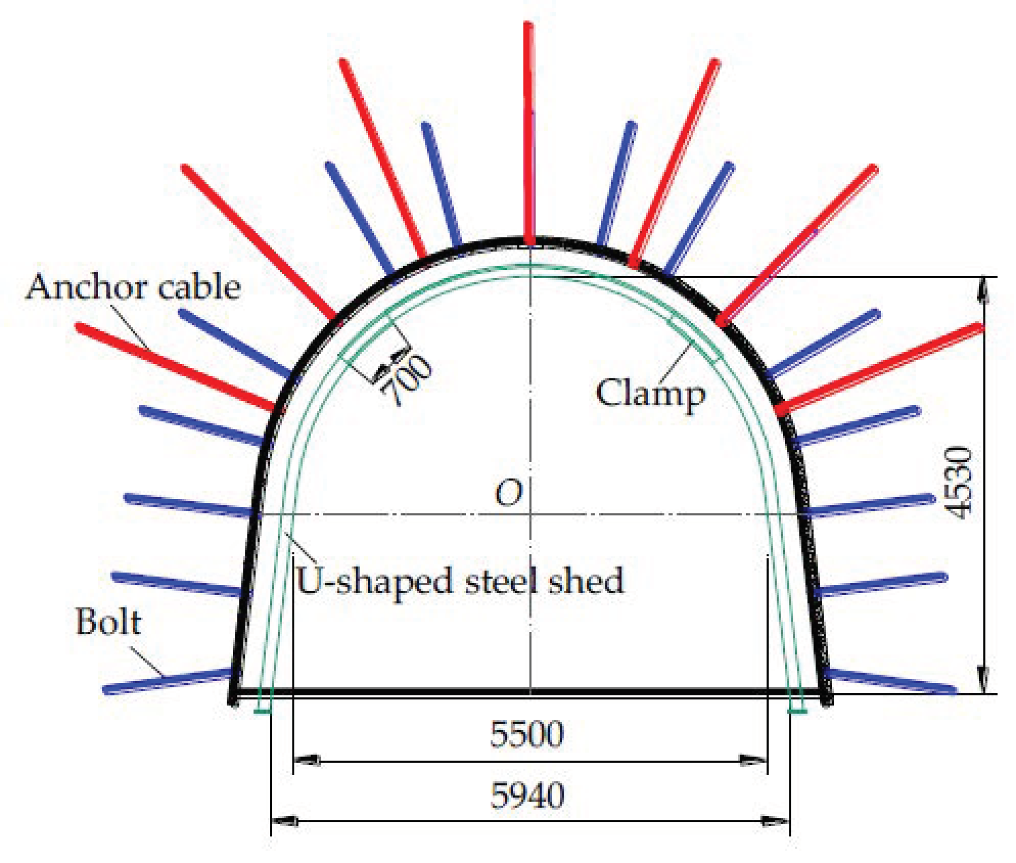
4.1. U-Shaped Steel Secondary Shed Passive Support Technology

The U-shaped steel shed has the advantages of strong bearing capacity, good stability, and high compressibility, which can improve the shallow stress environment of the roadway surrounding rock and improve the crushing surrounding rock’s residual strength by passively restraining the rock mass deformation [32,33]. The combination of passive and active supports can give full play to the bearing performance of the two types of support and greatly improve the overall supporting strength of the surrounding rock structure. Based on the combined support of “bolt mesh cable shotcrete”, the U-shaped steel secondary shed passive support (see Figure 6) was implemented for the west-wing main track roadway. The basic mechanical performance of the U-shaped steel beam is summarized in Table 2.
The parameters of passive support technology for U-shaped steel secondary shed were as following:
A three-section shed manufactured from 36 U-shaped steel beams was adopted for the secondary shed passive support, the clear width of arch foundation was 5500 mm, the pure height of arch foundation was 4530 mm, the pure width of the bottom corner was 5940 mm, and the shed middle-to-middle spacing was 650 mm; the overlapping length of shed beam and shed leg was 700 mm; the clamp was made of the 36 U-shaped steel beams, the clamp bolt specification was Φ30 × L160 mm, with the torque of no less than 300 N·m. The filling thickness reserved in the main roadway section was 250~350 mm.

4.2. Backwall Rapid-Setting Material Filling and Control Technology

Backwall filling can compact the gap between the main roadway surrounding rock and the U-shaped steel shed, generating a common mechanical bearing system between the surrounding rock, filling body, and support structure, in order to improve the overall coupling effect [34]. Based on the above combined support of “bolt mesh cable shotcrete” and secondary shed passive support, the automatic filling system produced by the Ruhr Group, Germany, was used to fill the setting material behind the wall of the west-wing main track roadway (see Figure 7), so as to further control the main roadway surrounding rock deformation. The filling material was prepared from cement, slag, and yellow sand. Table 3 shows the relationship between the curing time and strength.
The construction process of filling and compacting quick-setting materials behind the wall was as follows:
(1)
First, lay the reinforcement mesh behind the U-shaped steel shed, and then lay the plastic cloth from the shed top to both sides;
(2)
At the starting and end positions of filling, stack woven bags filled with sand to form isolation belts, and arrange a filling window on the top of the U-shaped steel shed and two shoulder sockets, respectively;
(3)
The equipment is used to mix the mixture with water to form concrete; then, it is transferred to the filling place for backwall filling by concrete pump;
(4)
The head of the filling pipe is fixed by ladder. First, fill the side profile of the main roadway (the two walls are filled alternately), and then fill the top of the main roadway;
(5)
When the material reaches the filling window position, the filling is completed and stopped. Use woven bags or plastic cloth to block the shoulder socket window tightly, and then use 10# iron wire to fix it, and then fill the top window;
(6)
The hose is adopted for concrete delivery pump with sufficient compressive capacity (the pressure resistance shall be no less than 10 MPa), and its length can be subdivided into 10, 15, and 20 m long sections. The maximum delivery distance shall not exceed 150 m.

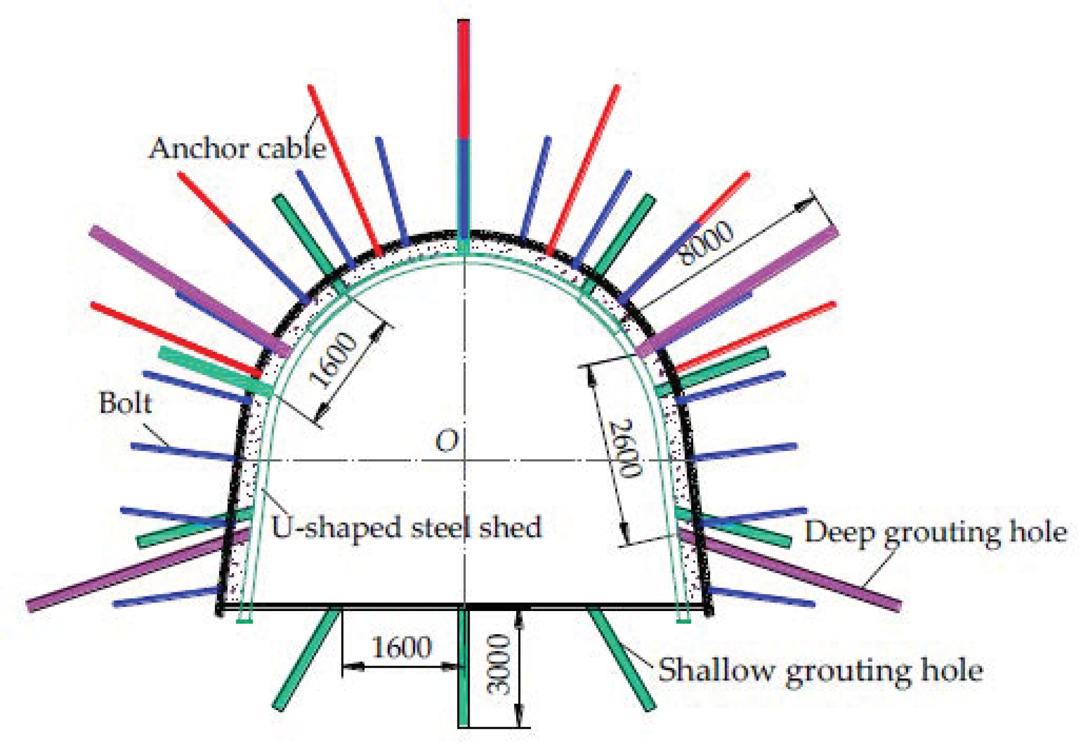
4.3. Grouting Reinforcing Technology with Combined Deep and Shallow Holes (GR-CDSH)

Grouting reinforcement is a strengthening method of injecting slurry into the crushing surrounding rock to induce physical and chemical interaction, which can effectively improve the bearing capacity of the surrounding rock and control the plastic deformation. According to the specific geological conditions of the west-wing main track roadway, based on the above combined support of “bolt mesh cable shotcrete”, secondary shed passive support, and the backwall rapid-setting material filling and control technology, it was proposed to use the grouting pipe to implement the grouting reinforcement with combined deep and shallow holes (GR-CDSH) for the main roadway surrounding rock, as shown in Figure 8. It was envisaged to further improve the overall stability of the main roadway surrounding rock. The technical parameters of GR-CDSH were as follows:
(1)
GR parameters of roof: Each row of main roadway roof was symmetrically arranged with three deep grouting holes with a depth of 8000 mm, and the row spacing was 2600 × 9600 mm, grouting pressure was 4.5 MPa; three shallow grouting holes with a depth of 3000 mm were symmetrically arranged with a row spacing of 1600 × 4800 mm, and the grouting pressure was 2.0 MPa.
(2)
GR parameters of the two walls: Each row of the main roadway’s two walls was symmetrically arranged with two deep grouting holes with a depth of 8000 mm, and the grouting pressure was 3.5 MPa; four shallow grouting holes with a depth of 3000 mm were arranged symmetrically. Other reinforcement parameters were the same as roof support.
(3)
GR parameters of floor: As an important transportation, ventilation, and pedestrian passage of the KCM, the main roadway floor of the west-wing main track roadway was required to lay tracks to ensure the safety of material transportation. Therefore, the stability of the main roadway floor should be strictly controlled to avoid large floor heave deformation. Three shallow grouting holes with a depth of 3000 mm were symmetrically arranged in the main roadway floor, and the spacing and grouting pressure of these were the same as that of the GR parameters of roof.

5. Effect Analysis of the Industrial Field Test

5.1. Field Observation Scheme Design

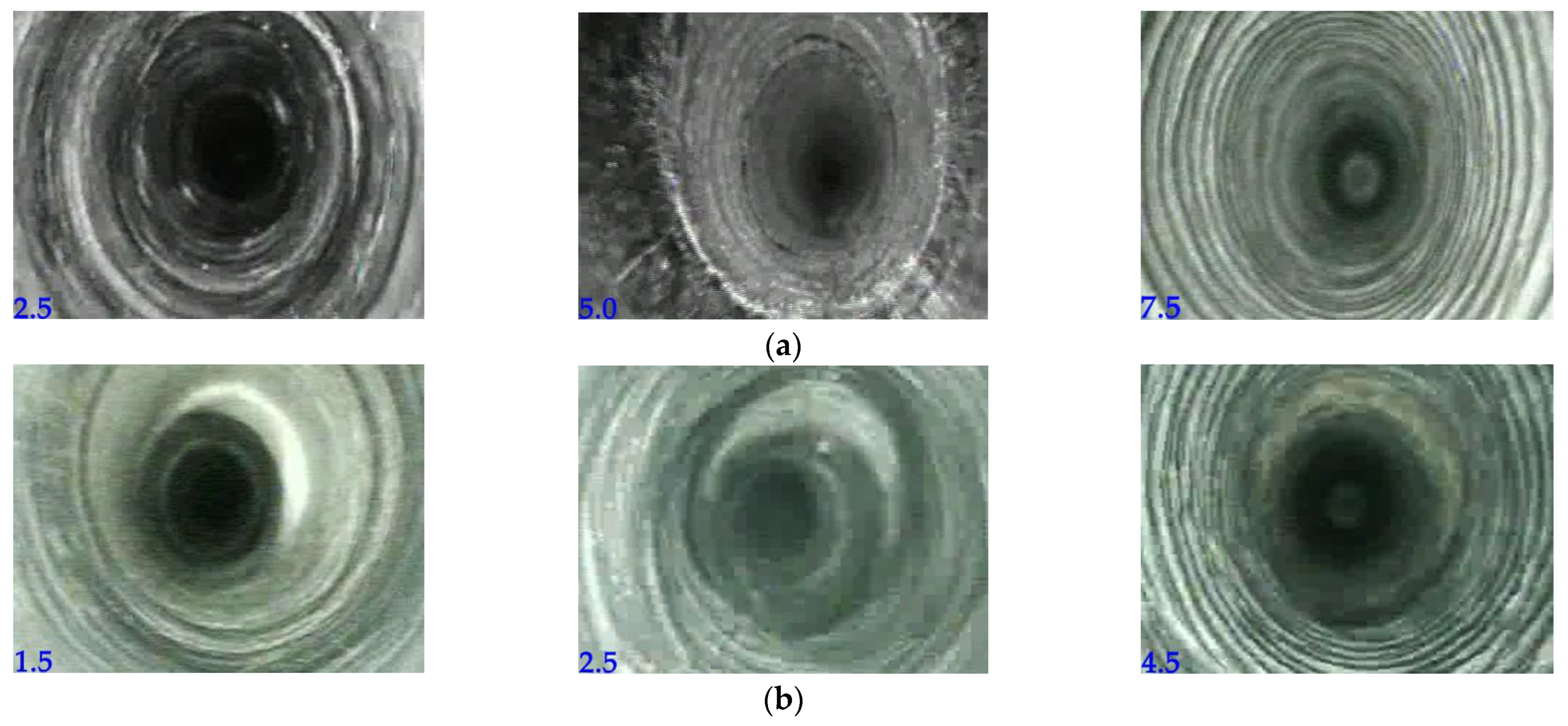
5.1.1. Borehole Peeping of Deep Failure Characteristic of the Surrounding Rock in the Main Roadway

Three stations (see Figure 9) were arranged at an equal distance of 20 m in the main roadway test section, and a YTJ20 borehole peep instrument was used to examine the failure of deep surrounding rock in the main roadway. There were seven Φ32 mm peep holes in each station section, including three holes in the roof, two in the two walls, and two in the floor. The roof hole depth was 8000 mm, while depths of the side profile and bottom holes were 5000 mm.

5.1.2. Field Observation of Surface Displacement of the Surrounding Rock in the Main Roadway

The number and location of stations for monitoring of surface displacement of surrounding rock in the main roadway were the same as those of borehole peeping stations. The measuring base points were arranged in the center of the main roadway’s roof, floor, and the two walls. The “cross-measurement method” was used for continuous monitoring for three months, and the surrounding rock deformation of the main roadway was recorded, as shown in Figure 9b. On the basis of the displacements of the excavation contour in the surrounding rock, it is possible to estimate the deformation of the future excavation performed in similar geological and mining conditions [35].

5.2. Field Test

Figure 10 shows the west-wing main track roadway surrounding rock deep’s failure characteristic borehole peeping results.
It can be seen from the peep borehole observations that the grouting slurry could effectively fill the surrounding rock cracks and bond them into a relatively complete structure. The cracking and fracturing of the main roadway surrounding rock were inhibited significantly. The overall stability and integrity of the surrounding rock were good. Although a small amount of microcracks occurred occasionally, there were no obvious traces of separation, dislocation, fracture, or other phenomena. It can be seen that the “shielding-filling-grouting” integrated collaborative control technology system achieved good application results in the west-wing main track roadway.
Figure 11 exhibits trends of surface displacement of the surrounding rock in the west-wing main track roadway obtained by field observation. As observed, the west-wing main track roadway #1 station roof and floor, as well as left- and right-wall displacements, finally reached 58, 46, 33, and 32 mm to reach stability. The #2 station’s roof and floor, as well as left- and right-wall displacements finally reached 54, 44, 30, and 33 mm to reach stability; #3 station’s roof and floor, as well as left- and right- wall displacements reached 51, 43, 32, and 36 mm to reach stability. The average changes in the displacements of rock surrounding the roof, floor, and two walls were only 54, 44, 32, and 34 mm, respectively. The overall deformation of the surrounding rock was small, suggesting that the integrated collaborative control scheme of “shielding-filling-grouting” could significantly reduce the deformation failure of the surrounding rock in the main roadway and effectively maintain the overall stable state of the main roadway’s surrounding rock, satisfying the requirements of the mine’s long-term exploitation.

6. Conclusions

Using a case study of the KCM (Fuyang, China), we analyzed its −967 m level west-wing main track roadway, as a typical 1 km deep large-section roadway. The results obtained made it possible to draw the following conclusions:
(1)
Field measurement of the in-situ stress in the study area revealed that the in-situ stress state was dominated by the horizontal in-situ stress, showing typical structural stress field features. When the original “bolt mesh cable shotcrete” combined support scheme was adopted for the main roadway, the roadway surrounding rock presented full-section nonlinear deformation failure features, breaching the requirements of mine safety production.
(2)
The analysis of elastoplastic mechanism of deformation failure of the surrounding rock in the main roadway revealed that the main roadway surrounding rock structure distribution was related to the original physical and mechanical properties of the rock mass, stress environment, and support mode. The main reasons for the above failure mode were the low strength of the main roadway surrounding rock, the complex stress environment of the horizontal structure, the insufficient support scheme strength of the original “bolt mesh cable shotcrete”, and the lack of effective control measures for the main roadway floor.
(3)
Aiming at the specific engineering geological conditions of the west-wing main track roadway and considering the advantages and disadvantages of the main roadway’s original support scheme, a set of targeted “shielding-filling-grouting” integrated collaborative control technology system was proposed. It mainly included the U-shaped steel secondary shed passive support technology, the quick-setting material filling and compaction control technology behind the wall, and GR-CDSH support technology.
(4)
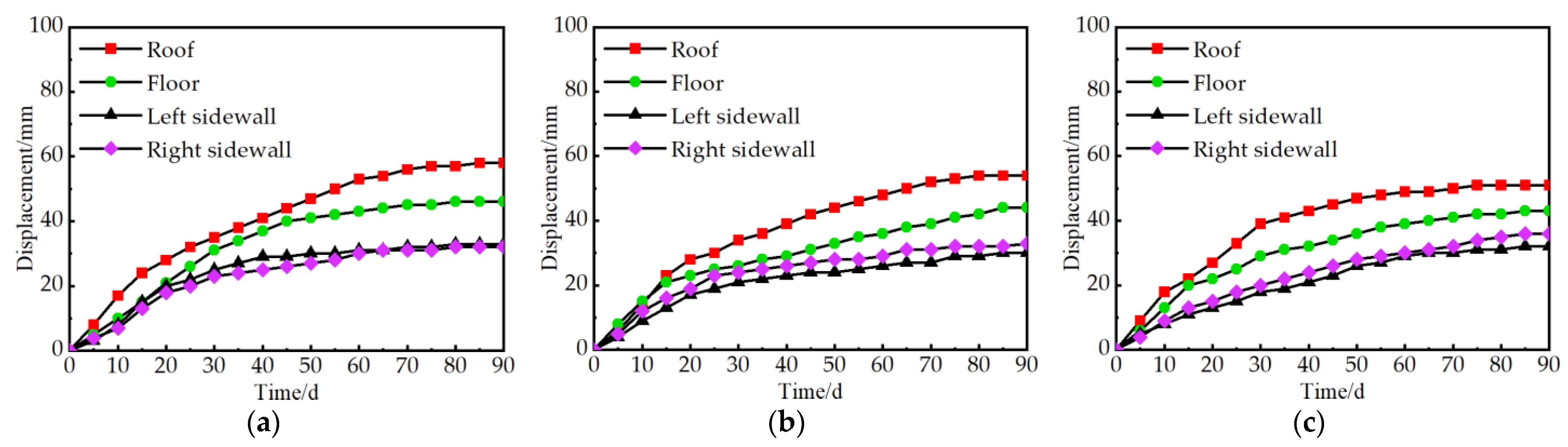
The industrial field test revealed that when the integrated collaborative control scheme of “shielding-filling-grouting” was adopted in the main roadway, the grouting slurry could effectively fill the surrounding rock’s crack and bond with it to form a relatively complete structure, achieving a sound grouting effect. The average changes in the displacements of rock surfaces surrounding the main roadway roof, floor, and two walls were 54, 44, 32, and 34 mm, respectively. There were no severe deformation failures in the surrounding rock. The proposed scheme achieved strength improvement and structural compensation of the weak position of the main surrounding rock, provided the active and passive support collaborative control, guaranteed the long-term stability of the roadway, and ensured the safety of staff and equipment, satisfying the requirements of mine safety and efficient production.

Author Contributions

Conceptualization, W.Z., L.C. and Y.Z. (Yandong Zhang); Data curation, J.T. and L.C.; Funding acquisition, W.Z.; formal analysis, Y.Z. (Yanchao Zhu) and Z.S.; Investigation, J.T. and L.C.; Methodology, Y.Z. (Yandong Zhang); Resources, W.Z.; Supervision, W.Z.; Writing—original draft, J.T.; Writing—review and editing W.Z., Y.Z. (Yandong Zhang), J.T. and Y.Z. (Yanchao Zhu). All authors have read and agreed to the published version of the manuscript.

Funding

This work was financially supported by the National Natural Science Foundation of China, grant number 51874278, the “Six Talent Peaks” Project of Jiangsu Province, grant number JNHB-087, and the Independent Research Project of State Key Laboratory of Coal Resources and Safe Mining, grant number SKLCRSM2020X04.

Conflicts of Interest

The authors declare no conflict of interest.

References

  1. Xie, H.; Wang, J.; Wang, G.; Ren, H.; Liu, J.; Ge, S.; Zhou, H.; Wu, G.; Ren, S. New ideas of coal revolution and layout of coal science and technology development. J. China Coal Soc. 2018, 43, 1187–1197. [Google Scholar]
  2. Zhang, N.; Li, X.; Zheng, X.; Xue, F. Current status and challenges of deep coal mining. In Proceedings of the National Symposium on Mining Technology of Kilometer Deep Coal Mine, Tai’an, China, 25 July 2013. [Google Scholar]
  3. He, M.; Xie, H.; Peng, S.; Jiang, Y. Study on rock mechanics in deep mining engineering. Chin. J. Rock Mech. Eng. 2005, 24, 2803–2813. [Google Scholar]
  4. He, M.; Wang, X.; Liu, W.; Yang, S. Numerical simulation on asymmetric deformation of deep soft rock roadway in Kongzhuang Coal Mine. Chin. J. Rock Mech. Eng. 2008, 27, 673–678. [Google Scholar]
  5. Shen, B. Coal mine roadway stability in soft rock: A case study. Rock Mech. Rock Eng. 2014, 47, 2225–2238. [Google Scholar] [CrossRef]
  6. Liu, W.; Guo, Z.; Wang, C.; Niu, S. Physico-mechanical and microstructure properties of cemented coal Gangue-Fly ash backfill: Effects of curing temperature. Constr. Build. Mater. 2021, 299, 124011. [Google Scholar] [CrossRef]
  7. Skrzypkowski, K.; Zagórski, K.; Zagórska, A.; Apel, D.B.; Wang, J.; Xu, H.; Guo, L. Choice of the arch yielding support for the preparatory roadway located near the fault. Energies 2022, 15, 3774. [Google Scholar] [CrossRef]
  8. Hou, C.; Wang, X.; Bai, J.; Meng, N.; Wu, W. Basic theory and technology study of stability control for surrounding rock in deep roadway. J. China Univ. Min. Technol. 2021, 50, 1–12. [Google Scholar]
  9. Xie, H.; Gao, M.; Zhang, R.; Peng, G.; Wang, W.; Li, A. Study on the mechanical properties and mechanical response of coal mining at 1000 m or deeper. Rock Mech. Rock Eng. 2019, 52, 1475–1490. [Google Scholar] [CrossRef]
  10. Kang, H. “Strata control and intelligent mining technology in deep coal mines with depth more than 1000 m” Guest editor of the album to readers. J. China Coal Soc. 2020, 45, 1211–1212. [Google Scholar]
  11. Ma, Q.; Tan, Y.; Liu, X.; Zhao, Z.; Fan, D. Mechanical and energy characteristics of coal-rock composite sample with different height ratios: A numerical study based on particle flow code. Environ. Earth Sci. 2021, 80, 1–14. [Google Scholar] [CrossRef]
  12. Jing, H.; Wu, J.; Yin, Q.; Wang, K. Deformation and failure characteristics of anchorage structure of surrounding rock in deep roadway. Int. J. Min. Sci. Technol. 2020, 30, 593–604. [Google Scholar] [CrossRef]
  13. Fu, Y.; Ju, W.; Wu, Y.; He, J.; Jiao, J. Study on principle application of energy absorption and bump reduction of high impact toughness rock bolt. Coal Sci. Technol. 2019, 47, 68–75. [Google Scholar]
  14. Yang, J.; Yang, S. Experimental study on reinforcement of deep soft roadway by using ACZ-1 modified grouting material. Saf. Coal Mines 2017, 48, 60–64. [Google Scholar]
  15. Yu, Y.; Qin, Z.; Wang, X.; Zhang, L.; Chen, D.; Zhu, S. Development of modified grouting material and its application in roadway repair engineering. Geofluids 2021, 2021, 1–15. [Google Scholar] [CrossRef]
  16. Zhang, H.; Zhou, R.; Liu, S.; Zhu, Y.; Wang, S.; Wang, J.; Guan, X. Enhanced toughness of ultra-fine sulphoaluminate cement-based hybrid grouting materials by incorporating in-situ polymerization of acrylamide. Constr. Build. Mater. 2021, 292, 123421. [Google Scholar] [CrossRef]
  17. Oggeri, C.; Oreste, P.; Spagnoli, G. Creep behaviour of two-component grout and interaction with segmental lining in tunnelling. Tunn. Undergr. Space Technol. 2022, 119, 104216. [Google Scholar] [CrossRef]
  18. Kang, H.; Jiang, P.; Huang, B.; Guan, X.; Wang, Z.; Wu, Y.; Gao, F.; Yang, J.; Cheng, L.; Zheng, Y.; et al. Roadway strata control technology by means of bolting-modification-destressing in synergy in 1000 m deep coal mines. J. China Coal Soc. 2020, 45, 845–864. [Google Scholar]
  19. Zhang, Z.; Kang, H.; Jiang, Z.; Li, W.; Jiang, P.; Cai, R.; Zhu, Y.; Wang, J. Study and application of high-pressure splitting grouting modification technology in coalmine with depth more than 1000 m. J. China Coal Soc. 2020, 45, 972–981. [Google Scholar]
  20. Huang, B.; Zhang, N.; Jing, H.; Kan, J.; Meng, B.; Li, N.; Xie, W.; Jiao, J. Large deformation theory of rheology and structural instability of the surrounding rock in deep mining roadway. J. China Coal Soc. 2020, 45, 911–926. [Google Scholar]
  21. Zhang, G.; Zhu, W.; Zhao, P. In-situ stress measurements and analysis of action of geological structures of deep coal mines in Xuzhou. Chin. J. Geotech. Eng. 2012, 34, 2318–2324. [Google Scholar]
  22. Qin, W.; Gui, S. Field study on ground stress distribution laws in Huainan Mining Area. Saf. Coal Mines 2013, 44, 185–188. [Google Scholar]
  23. Yang, R.; Chen, J.; Xue, H.; Cheng, C.; Wang, W. Research of influencing factors of coalmine ground stress test precision by stress relieving method. China Min. Mag. 2014, 23, 136–139. [Google Scholar]
  24. Wu, H.; Zhao, G.; Ma, S. Failure behavior of horseshoe-shaped tunnel in hard rock under high stress: Phenomenon and mechanisms. Trans. Nonferr. Met. Soc. China 2022, 32, 639–656. [Google Scholar] [CrossRef]
  25. Wang, Q. Study on the Relationship between Kou Zidong Mine Deep Crustal Stress Distribution and Roadway Layout. Master’s Thesis, Anhui University of Science and Technology, Huainan, China, 2014. [Google Scholar]
  26. Shen, M.; Chen, J. Rockmass Mechanics, 1st ed.; Tongji University Press: Shanghai, China, 2006; pp. 142–184. [Google Scholar]
  27. Podkopaiev, S.; Gogo, V.; Yefremov, I.; Kipko, O.; Iordanov, I.; Simonova, Y. Phenomena of stability of the coal seam roof with a yielding support. Min. Miner. Depos. 2019, 13, 28–41. [Google Scholar] [CrossRef]
  28. Zhao, G.; Zhang, X.; Wang, C.; Meng, X. Mechanical analysis and numerical simulation for deep and shallow bearing structures of soft and broken roadway surrounding rock. J. China Coal Soc. 2016, 41, 1632–1642. [Google Scholar]
  29. Wang, H.; Zhang, D.; Deng, D.; Jiang, Y.; Liu, Y. Stress distribution characteristics of roadway surrounding rock damaged zone under non-hydrostatic pressure. J. China Coal Soc. 2020, 45, 3717–3725. [Google Scholar]
  30. Yuan, W.; Chen, J. Analysis of plastic zone and damaged zone of roadway in softened rock stratum. J. China Coal Soc. 1986, 11, 77–86. [Google Scholar]
  31. Zuo, J.; Hong, Z.; Yu, M.; Liu, H.; Wang, Z. Study on gradient support model and classification control of borken surrounding rock. J. China Univ. Min. Technol. 2022, 51, 1–11. [Google Scholar]
  32. Wang, Q.; Xie, W.; Jing, S.; Zang, L.; Zhang, N. Research on U-shape steel frame and anchor cable collaborative support mechanism and loading law of roadway under dynamical pressure impact. J. China Coal Soc. 2015, 40, 301–307. [Google Scholar]
  33. Rotkegel, M.; Szot, Ł.; Fabich, S. The analysis of selected methods of the yielding of a circular arch support made of V profiles. Arch. Min. Sci. 2020, 65, 521–550. [Google Scholar]
  34. Xie, W.; Jing, S.; Wang, T.; Ren, Y.; Zhang, N. Structural stability of U-steel support and it’s control technology. Chin. J. Rock Mech. Eng. 2010, 29, 3743–3748. [Google Scholar]
  35. Skrzypkowski, K. Case studies of rock bolt support loads and rock mass monitoring for the room and pillar method in the legnica-głogów copper district in poland. Energies 2020, 13, 2998. [Google Scholar] [CrossRef]
Figure 1. Strata comprehensive column of the study area.
Minerals 12 00854 g001
Figure 2. West-wing main track roadway original support scheme (Unit: mm): (a) bolt support section; (b) Anchor cable support section; (c) Roadway roof support; (d) Roadway wall support.
Minerals 12 00854 g002
Figure 3. Azimuths of horizontal principal stresses at different stations: (a) G1 station; (b) G2 station; (c) G3 station.
Minerals 12 00854 g003
Figure 4. Deformation failure of the surrounding rock in the main roadway. (a) the roof; (b) the wall; (c) the floor.
Minerals 12 00854 g004
Figure 5. Zones in the main roadway surrounding rock.
Minerals 12 00854 g005
Figure 6. Secondary shed passive support scheme (Unit: mm).
Minerals 12 00854 g006
Figure 7. Backwall filling compaction control scheme.
Minerals 12 00854 g007
Figure 8. The GR-CDSH scheme (Unit: mm).
Minerals 12 00854 g008
Figure 9. Observation scheme of deep failure of the surrounding rock (Unit: mm): (a) station arrangement positions; (b) peep borehole parameters.
Minerals 12 00854 g009
Figure 10. The main roadway-surrounding rock observations via peep boreholes (Unit: m): (a) roof; (b) two walls; (c) floor.
Minerals 12 00854 g010aMinerals 12 00854 g010b
Figure 11. Surface displacement of the main roadway obtained by field observation: (a) #1 station curve; (b) #2 station curve; (c) #3 station curve.
Minerals 12 00854 g011
Table 1. In-situ stress measurement results obtained at different stations.
StationDepth (m)σ/MPaασHmax/MPaσHmin/MPaσV/MPaβγk1k2
G1960.50σ1 = 30.159.01°30.1521.0527.60N 112.54° EN 25.43° E1.091.43
σ2 = 27.64−69.54°
σ3 = 21.01−22.32°
G2958.50σ1 = 32.813.08°31.9714.0421.40N 120.71° EN 32.57° E1.492.28
σ2 = 20.58−57.31°
σ3 = 14.0139.01°
G3958.30σ1 = 36.101.48°37.2720.6324.30N 122.29° EN 33.28° E1.531.81
σ2 = 24.32−69.47°
σ3 = 16.7818.54°
Table 2. Basic mechanical performance parameters of the U-shaped steel shed.
Steel GradeSpecificationYield Stress
(MPa)
Tensile Trength
(MPa)
Elongation
(%)
20 MnK36 U40055018
Table 3. Correlation of filling material’s curing time with the sample strength.
Time (h)5122448
Compressive strength (MPa)5101520
Publisher’s Note: MDPI stays neutral with regard to jurisdictional claims in published maps and institutional affiliations.

