Abstract
Backfilling is commonly used in underground mines to improve the stability of overlying strata. The performance of the backfill and its interaction with surrounding rock are the key issues in backfill mining research. In this paper, the displacement and stress field evolution characteristics of the overlying strata in backfill mining were analyzed by a physical model, as well as the interaction between the backfill and surrounding rock. The research results show that when backfill mining is employed, the backfill mass and the unexcavated rock mass jointly bear the loads of the overlying strata. The loads of the overlying strata are transferred to the dense backfill mass and the surrounding rock. The stress in the near-field area of the surrounding rock increases and stabilizes gradually. The backfill mass improves the stress distribution state and reduces the stress concentration of the surrounding rock, which is conducive to preventing the progressive damage of the overlying strata. In addition, the backfill mass excavation has a significant influence on the stability of the overlying strata and the surrounding rock stress field. The backfill mass is a passive force-bearing structure that can effectively manage the deformation of the overlying strata and the phenomenon of underground pressure.
1. Introduction
Under the conditions of open stope mining, the gradual increase in the exposed area of the goaf would inevitably lead to the deformation and caving of the overlying strata and even surface subsidence, threatening the safety of surface structures and further underground mining activities [1]. Backfill mining is an effective method to resolve the problems of strata movement and surface subsidence in mine sites [2,3,4,5]. The mechanical properties of the backfill and its interaction with surrounding rock are the key issues in backfill mining research [6]. Falaknaz [7] employed numerical simulation to examine the stress and displacement variation of adjacent filling stopes, taking into account factors such as rock mass characteristics, stope geometry, depth, and mining-filling sequence. The results demonstrate that mining and filling significantly impact the stress distribution of adjacent stopes, and the arching effect dominates the stress distribution in the stopes. According to M. Aubertin [8], the arching effect that can appear in fill mass may have a major impact on load distribution along the stope walls and at the bottom of narrow stopes. The load transfer can be considerable, reducing both the horizontal stress on the stope walls and the vertical stress on the floor. However, F.P. Hassani [9] considered that the stress distribution in inclined stopes is extremely complicated, and the analytical solutions based on arch theory are unsuitable for inclined stopes. To address the issue of arch effect, Jahanbakhshzadeh [10] introduced a new analytical solution for the stress state in inclined backfilled mine stopes based on the Marston arching equation, which takes into account the coefficient of lateral stress, stope geometry, backfill strength, and the stope walls inclination angle. Cui [11,12] developed an integrated multiphysics model to assess and predict the arching effects of field cemented tailings backfill (CTB), and then utilized it to simulate a range of CTB-related applications. It is apparent that arching has a significant effect on the total stress in the stope. The results illustrate that it is a useful approach for analyzing the interaction of the backfill mass with surrounding rocks. You [13] investigated the interaction between the fill mass and the surrounding rock, as well as the influence of additional stress in the open stope subsequent filling method. The stress of the backfill roof was analyzed based on the Terzaghi theory, and a backfill mass strength calculation method was developed. M. A. Sobhi [14,15] considered that the vertical and horizontal stresses of the overlaying backfill increased with stope depth, earth pressure coefficient, backfill stiffness, and Poisson’s ratio. To characterize the shear behavior of the interface between cemented paste backfill (CPB) and surrounding rock under the combined impacts of thermal, chemical, and mechanical circumstances, Fang [16,17] suggested a thermo-chemo-mechanical cohesive zone model (CZM), which has been confirmed by numerical simulation and laboratory experiments. The results indicate that the model could be employed to conduct assessments on the backfill-rock interface after the CPB has been placed in the stopes. Yu [18] investigated the dynamic stability of pillars and backfill mass in the open stope subsequent cemented filling method using numerical simulation and in-situ ground pressure detection methods. It is considered that the backfill mass can reduce the stress concentration in the roof and the two sides of the stope and efficiently preserve the stope’s stability. Tan [19] performed an experimental investigation into the different pressure-bearing combinations of the backfill mass and the surrounding rock. The findings revealed that the backfill mass had a supporting and protective effect on the surrounding rock and increased the residual strength of the pressure-bearing combination. Yu [20] monitored the deformation of the surrounding rock on the hanging wall using a multi-point displacement meter, and the control effect of the backfill on the deformation of the surrounding rock was investigated. The results show that the surrounding rock is mostly elastically deformed during the early stages of mining, and that filling in the deformation lag period may effectively control the movement and deformation of the surrounding rock. Although the backfill’s capacity to carry the overlaying rock is restricted, it can significantly decrease the overlying rock’s movement and deformation. Wang [21] and Yao [22] studied the stress characteristics of the surrounding rocks, pillars, and backfill using physical models, as well as the bearing mechanism of backfill, the evolution of overlying rock deformation, and surface subsidence. Zhu [23] proposed a superposition subsidence prediction model for backfill-strip mining based on the probability integral method to forecast surface subsidence, which has been validated by similar simulation experiments and numerical simulations. According to the conclusions, surface subsidence is caused by the combination of backfill compression and roof caving. Zha [24] and Bai [25] investigated the action mechanism of non-cemented backfill in controlling surface subsidence and concluded that backfill slows down the subsidence and that the compaction degree of the backfill is the most important factor determining the subsidence of the overlying strata. However, the filling rate also affects the failure and stress characteristics of the overlying strata. In a low filling rate condition, the distribution range of overburden fractures expands; additionally, vertical displacement differentiation becomes more apparent. In the case of a high filling rate, the displacement of the overlying strata mainly occurs near the immediate roof [26]. The backfill provides overlying strata support, which is conducive to limiting the deformation and reducing the stress concentration in the rock mass and maintaining the mining region’s stability [27]. That is to say, backfilling is an effective way to improve the stability of the rock strata [28,29].
The movement of the overlying strata and the variation of the stress field induced by underground mining are extremely complicated. However, there are few studies on the specific geological conditions of the Hongnipo Copper Mine, and the previous work has laid a solid foundation for this study. The objective of this study is to investigate the possibility of overburden strata movement and surface subsidence in the underground mining of Hongnipo Copper Mine, as well as the interaction between backfill and surrounding rock to be studied through a physical model. Firstly, the physical model is used to reproduce the underground backfilling method practiced in Hongnipo Copper Mine. Then, following the completion of mining and stabilization of the surrounding rock, the backfill mass is sequentially excavated downward by sublevels. Finally, the influence of the backfill on the displacement and stress fields of the overlying strata is verified in reverse, and the action mechanism of the backfill governing the overburden stability is discussed. This research provides theoretical direction for the safe mining of the Hongnipo Copper Mine as well as the assessment of surface infrastructure safety. On the other hand, this work is a valuable supplement to the existing research on the interaction between backfill and surrounding rock.
2. Experimental Method
2.1. Basic Conditions
According to mine geological data, the surface of the research area is mainly composed of Quaternary (Q) loose deposits, with an average thickness of 50–120 m; the indirect rock overburden (Pt1t2) is mainly composed of biotite schist, quartz albite, and marble, with a thickness ranging from 45–140 m. It is a soft rock formation with poor rock mass quality. The primary lithology of the direct rock overburden (pt1t1) is quartz albite and dolomite albite, with an average thickness of 90–140 m and poor-medium rock quality. The average thickness of the copper ore deposit is 25 m, the dip angle is mostly no more than 22–24°, the surface elevation is about 1880 m, and the shallowest depth of the deposit is approximately 60–390 m. The floor (Pt1s) primarily consists of dolomite-quartz schist, dolomite marble, and black carbonaceous slate and has an average thickness of 120–180 m. It is a medium-mass semi-hard rock formation. The strata distribution of the physical model is shown in Figure 1. Because of the shallow burial of some ore deposits, it is challenging to determine whether the deformation and damage of the overlying strata caused by the mining activities will lead to instability problems for surface structures. Therefore, the overhand cut-and-fill method is intended to be used to extract the shallow ore bodies with an elevation ranging from 1700 m to 1800 m.
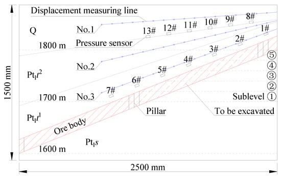
Figure 1.
Layout of the physical model.
2.2. Physical Model
Physical modeling is able to effectively investigate the stress distribution and the failure behavior of overlying strata in underground mining [30,31,32,33]. According to the previous research [34], the dimensions of the simulation platform are (length × width × height) 2500 mm × 300 mm × 1500 mm. The physical model’s constant of geometry (Cl) and the bulk density similarity ratio (Cγ) are 200 and 1.35, respectively. The arrangement of displacement measuring lines (No.1–No.3) and pressure sensors (1#–13#) is shown in Figure 1. The excavation is carried out in sublevels upward while following the ore body’s inclination direction from 1700 m to 1800 m throughout the test. The pillar width is set at 20 m, which is similar to the height of the sublevels. The working face advancement is shown as ①–⑤ sublevels in Figure 1. The excavation scale is the horizontal thickness of the ore body. The stope is backfilled once each sublevel of excavation is completed. Then, the strata displacement is measured by a high-precision total station, and the strain gauge continuously collects the stress data. The mechanical parameters of similar materials are shown in Table 1. The physical model and data acquisition system are shown in Figure 2.

Table 1.
The mechanical parameters of similar materials.
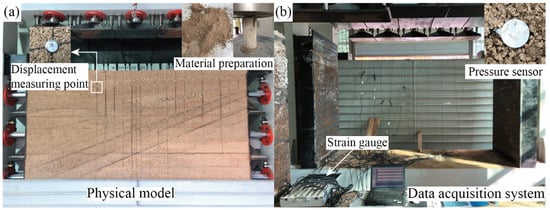
Figure 2.
The physical model and data acquisition system: (a) Physical model; (b) Data acquisition system (Pressure sensors: LY-350; Measuring range: 0–100 kPa; Resolving power % F·S ≤ 0.05; Overall dimension: 28 × 9 mm; Impedance: 350 Ω).
3. Test Result Analysis
3.1. Backfilling Mining
Figure 3 depicts the process of the experimental excavation. After excavating the first and second sublevels, the exposed area of the roof is limited, and the overlying strata do not fall off under the condition of an open stope, as shown in Figure 3a,b. Then the first and second sublevels are backfilled, as illustrated in Figure 3c. Next, the third, fourth, and fifth sublevels are sequentially excavated and backfilled, as indicated in Figure 3d–f. It can be seen that the overlying strata of the stope did not collapse after filling.
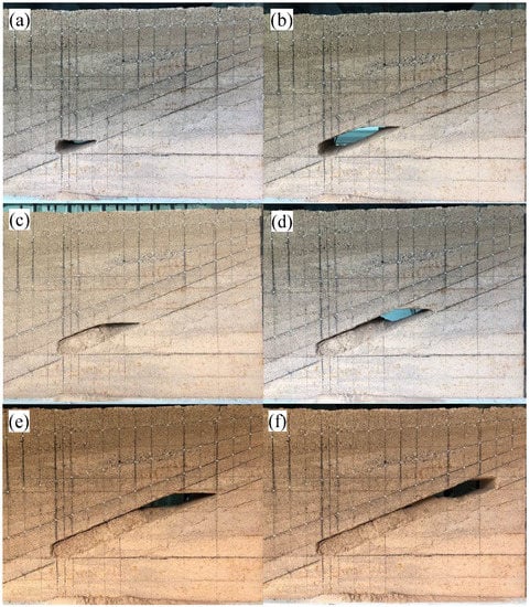
Figure 3.
Mining and filling process of similar simulation experiment: (a) The first sublevel mining; (b) The second sublevel mining; (c) The second sublevel filling; (d) The third sublevel mining; (e) The fourth sublevel mining; (f) The fifth sublevel mining.
3.2. Backfill Mass Excavation
To investigate the effect of backfill mining (backfill mass) on the deformation and caving of the overlying strata, the backfill mass is sequentially excavated downward by sublevels after the fifth sublevel of mining is completed and the surrounding rock becomes stable. That is, the backfill mass excavation is performed from the ⑤ sublevel to the ① sublevel, as shown in Figure 1. The displacement and stress field variation of the overlying rock are analyzed, and the action mechanism of the backfill on the surrounding rock is discussed in reverse. Figure 4 depicts the excavation of the backfill mass. Because of the increased exposed area of the goaf when the backfill mass is excavated to the second sublevel, a considerable amount of overlying rock falls, as seen in Figure 4c. Furthermore, the overlying strata continuously collapse over time, as illustrated in Figure 4d.
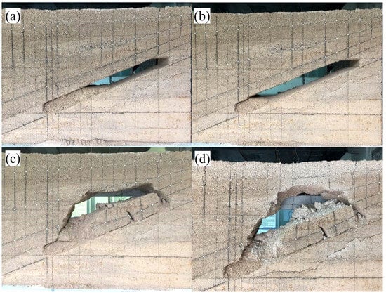
Figure 4.
Excavation process of backfill mass: (a) Backfill mass excavation to the third sublevel; (b) Backfill mass excavation to the second sublevel; (c) Overlying strata caving; (d) Overlying strata continuous caving.
The overlying strata progressively collapse when the backfill is excavated. The evolution process is shown in Figure 5, where a, b, c, and d correspond to Figure 4.
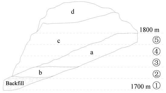
Figure 5.
The evolution of the overlying strata caving.
4. Displacement and Stress Analysis of Overlying Strata
4.1. Displacement Analysis of Overlying Strata in Backfill Mining
To facilitate the measurement and analysis of overlying strata displacement, assume the origin of the displacement measuring rectangular coordinate system is (1000, 1000), which is not directly related to the actual coordinates of the experimental model, and only this coordinate is used as the reference system to measure the coordinates of the rock formation. The displacement of the overlying strata is the relative change of each measuring point’s coordinates, and the strata’s displacement vector is shown in Figure 6. All the experimental measured values in Figure 6 can be converted into actual values using similar constants, and all subsequent analysis in the paper is based on the converted actual values.
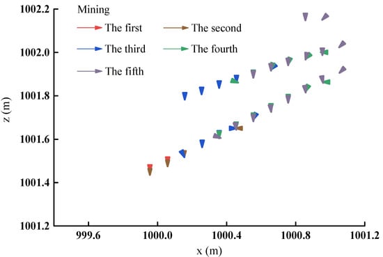
Figure 6.
Displacement vector of mining in each sublevel.
Following the mining of the first sublevel (see Figure 3a), only the roof close to the goaf has a definite displacement after mining the first sublevel from the displacement vector graph (see Figure 6). Moreover, the displacement is limited, which demonstrates that the exposed area of the goaf is modest, only the partial roof is disturbed to some extent by the excavation after the first sublevel of mining, and the roof as a whole has no apparent displacement and is in a stable state.
The exposed area of the roof gradually increased after the second sublevel was mined (see Figure 3b), and the rock formation near the goaf was disturbed and deformed. The influence scale of the overlying strata shows an increasing trend compared with the first sublevel of mining (see Figure 6). Due to the backfill’s supporting effect, the roof’s deformation is effectively controlled. As a result, the displacement of the roof is slight at this stage, and the structure as a whole remains stable.
When the third sublevel is mined (see Figure 3d), the exposed area of the goaf progressively increases as the working face continues to advance, leading to the disturbance range of the rock mass expanding. The displacement vector figure (see Figure 6) indicates that the second displacement measuring line of the overlying strata begins to move, suggesting that the strata disturbance gradually develops upward but has not yet reached the near-surface Quaternary overburden. However, the overlaying rock above the first and second sublevels is controlled to some extent by the progressive compaction of the backfill and does not continue to deform.
In addition, after the fourth sublevel is mined (see Figure 3e), the rock disturbance range develops upward along the inclination direction of the ore body with the continuous advancement of the working face, and the strata displacement has an increasing trend (see Figure 6). Despite that, the roof above the first, second, and third sublevels remained stable without continuous displacement due to the supporting effect of the backfill, and the Quaternary overburden near the surface did not subside.
Moreover, as the fifth sublevel is mined and the filling is completed (see Figure 3f), the working face has been advanced to the last sublevel, and the goaf has been filled to the fourth sublevel. It is evident from the displacement vector figure (see Figure 6) that the strata disturbance continues to develop along the inclination direction of the ore body and progressively extends upward to the near-surface Quaternary overburden. As a result, the Quaternary overburden directly above the goaf of the fifth sublevel is partially displaced with a slight displacement. However, due to the supporting function of the backfill mass, the roof above the first, second, third, and fourth sublevels remains stable. Accordingly, the support provided by the backfill increases regional and local strata stability [35,36].
4.2. Displacement Analysis of Overlying Strata in Backfill Mass Excavation
To analyze the response of the overlying strata’s movement after the backfill excavation, the fill mass was sequentially excavated downward by sublevels, and the displacement of the rock mass was collected. Figure 7 depicts the overlying strata’s displacement vector during the backfill excavation.
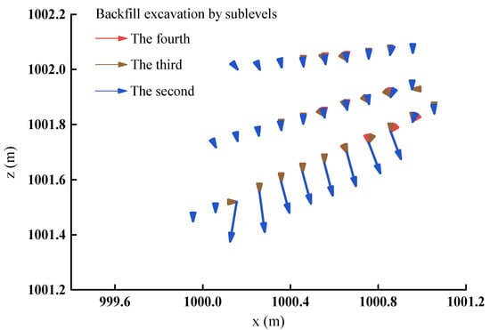
Figure 7.
Displacement vector of backfill excavation in each sublevel.
It can be seen from Figure 7 that after excavating the fourth sublevel backfill, the displacement of the roof directly above the goaf gradually increases, and the strata movement develops upward due to the gradual increase of the exposed area of the goaf. Meanwhile, the movement range of the near-surface Quaternary overburden shows an increasing trend compared with the former mining process. However, the overburden is generally in a stable state.
Furthermore, Figure 7 displays that after excavating the third sublevel backfill (see Figure 4a), the support effect of the backfill is diminished due to the continuous increase of the exposed area of the working face roof. Consequently, the movement range and displacement of the overlying strata continued to increase as well. The displacement of the overlying rock mass above goaf is around 0.8–1.2 m, with an approximate surface subsidence of 0.2 m.
The roof of the goaf comprises four sublevels of exposed space after excavating the second sublevel of the backfill (see Figure 4b). Since the exposed area was excessive and surpassed its limitation, resulting in large-scale caving in the roof of the goaf (see Figure 4c). The caving range along the inclined direction of the ore body is approximately 105 m, the vertical caving height is roughly 19–28 m, and the surface subsidence is about 0.4–0.6 m, all of which results in a significant impact on mining operations and the safety of surface structures.
After the roof collapses, the rock mass undergoes a self-stabilizing process over time in which stress transmission and redistribution occur to achieve a new equilibrium, leading to stress concentration in the roof. As a result, the roof continues to collapse (see Figure 4d) while the concentrated stress surpasses the load that the rock mass can take. Figure 8 illustrates the ultimate displacement vector of the overlying strata. The caving height of the goaf may approach 25–45 m, and the total surface subsidence displacement is approximately 0.8–1.2 m.
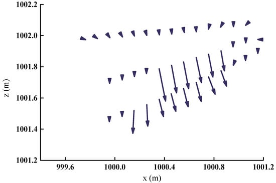
Figure 8.
Total displacement vector of overlying strata.
The above research results reveal that the displacement of the overlying strata, surface subsidence, and strata movement range continue to increase when the backfill is excavated, which eventually leads to a large area of roof collapse. The maximum caving height of goaf is around 45 m, while the maximum surface subsidence value is approximately 1.2 m. These behaviors pose a significant threat to the safety of underground mining and surface infrastructure. The findings demonstrate that the backfill has a controlling effect on the stability of the roof and that the backfilling method can effectively control the stability of the overlying strata and the surface structures.
4.3. Comprehensive Analysis of the Stress Field in Overlying Strata
The backfilling is carried out after each sublevel excavation in the physical model test, and the overlying strata stress distribution is tested using pressure sensors. The layout of the pressure sensors is shown in Figure 1, while Figure 9 and Figure 10 depict the variation of the overlying strata stress. The figure represents the test pressure value, which is transformed into the actual value using a similar constant. The stress values used in the following analysis are the converted actual values.
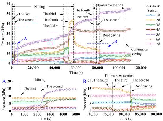
Figure 9.
Variation of 1#–7# pressure sensor stress in overlying strata: A, Enlarged view of the stress change in the first and second sublevels of mining; B, Enlarged view of the stress change during fill mass excavation.
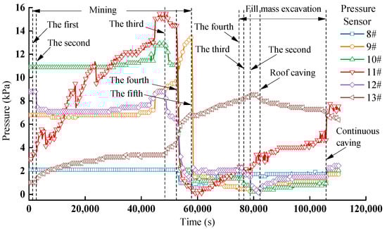
Figure 10.
Variation of 8#–13# pressure sensor stress in overlying strata.
The 7# pressure sensor is located near the ore pillar to be left in the downward direction of the ore body in the working face. It can be seen from the enlarged view of part A in Figure 9 that the value of the 7# pressure sensor stays steady, likely because the exposed area of the goaf is modest during mining of the first sublevel. It also demonstrates that the initial sublevel of mining does not disturb the rock mass around this area. However, the 6# pressure sensor is placed above the stope pillar, whereas the 5# pressure sensor is positioned closer to the stope roof. Both stress values are rising as a result of mining, but the value of the 5# pressure sensor has a somewhat greater growth rate than the 6# pressure sensor. The 4#, 3#, 2#, and 1# pressure sensors are far from the goaf, and the stress values are relatively stable. Therefore, the rock mass in this area has not been remarkably impacted by mining.
The 5# pressure sensor is positioned on the roof right above the stope while mining the second sublevel of the ore body. The mining disturbance significantly influences the rock mass because of the increased exposed area of the goaf, and the stress increases by 2.77 MPa. Meanwhile, the stress value of the 6# pressure sensor above the ore pillar increased by 1.31 MPa, suggesting that the stress was gradually transmitted to the rock mass at the lower end of the goaf. After filling, the stress growth ratio of 5# and 6# pressure sensors was reduced. However, 7#, 4#, and 3# pressure sensors all showed a tiny increasing trend, which indicates that the influence range of rock mass disturbance progressively extended. The 2# and 1# pressure sensors are distant from the goaf, and the stress values are stable, demonstrating that they are not currently affected by the mining.
After excavating the third sublevel of the ore body, the working face is gradually advanced upward along the inclination direction of the ore body. At that point, the 4# pressure sensor is directly above the stope’s roof. Figure 9 shows that its stress value decreases rapidly, indicating that the pressure of the overlying strata is relieved by the excavation of the stope, and it tends to be stable post-filling. On the other hand, the stress values of the 5#, 6#, and 7# pressure sensors showed an increasing tendency, demonstrating that the backfill mass performed a part in supporting and carrying the load with the overlying strata. In addition, the stress of the 3# pressure sensor in the roof of the goaf increases by 1.76 MPa, which indicates that the pressure from the overlying strata is transferred to the unexcavated rock mass at the end of the goaf. Furthermore, the 2# and 1# pressure sensors farther away from the goaf exhibit slight fluctuations, revealing that the disturbance range in this sublevel is greater than that in the second sublevel.
The stress value of the 3# pressure sensor placed directly above the stope was considerably diminished by 3.93 MPa after the fourth sublevel of the ore body was mined, and the stress progressively trended to be stabilized and increased after filling. As can be noticed, the disruption impact of the mining operation on the roof causes a significant change in the stress state of the overlying strata, which is not conducive to the roof’s safety control and management. However, the overlying strata generally tend to be stable after filling. As a result of the presence of the fill mass, the values of the 4# pressure sensor remained stable, while the stress of the 5#, 6#, and 7# pressure sensors were increased by 1.42 MPa, 1.97 MPa, and 1.05 MPa, respectively. It demonstrates that the backfill serves an important supportive role for the overlying strata. Additionally, the stress value of the 2# pressure sensor in the overlying strata increased significantly by 7.60 MPa. This is because the pressure of the overlying strata is transferred to the backfill and the unexcavated rock mass at both ends of the goaf, and the backfill and the unexcavated rock mass jointly bear the stress of the overlying strata to maintain the stability of the roof.
Following that, the ore body in the fifth sublevel is excavated. The stress value of the 2# pressure sensor in the roof just above the goaf drops sharply by 7.78 MPa and tends to be stable, and the strata stress is released to a great extent. The stress of the 1# pressure sensor in the unexcavated rock mass has increased significantly by 1.35 MPa and remained stable, indicating that the pressure of the overlying rock mass was transferred to the unexcavated rock mass, resulting in stress concentration near the end of the working face. Furthermore, the stress of the 3# and 4# pressure sensors remained roughly constant due to the action of the backfill, but the stress of the 5# pressure sensor increased rapidly by 2.83 MPa, revealing that the backfill had an adequate support impact on the overlying strata. Finally, the stress value of the 6# pressure sensor declined somewhat and then stabilized, whereas the stress of the 7# pressure sensor in the unexcavated rock mass farther from the working face remained stable.
The above analysis indicates that the disturbance caused by mining activities and backfilling may considerably alter the stress state in the backfilled stope [37]. With the continuous advancement of the working face, the overlying strata in the unfilled goaf lose the support from the ore body, and the strata pressure is released, resulting in the pressure sensor directly above the working face (goaf) exhibiting the law of stress reduction. However, the stress above the two ends of the working face (the backfill mass and the unexcavated rock mass) grows significantly. The experimental results reveal that under dynamic mining operations, the pressure of the overlying strata is transferred to both ends of the working face, and the backfill mass and the unexcavated rock mass carry the overburden loads together to keep the roof stable. The backfill mass is beneficial to the safety control of the roof.
Remove the backfill mass by sublevels whilst the mining is finished, and the strata stress is steady. The overlying strata stress variation rule is analyzed in which the backfill mass and the surrounding rock act in common. The exposed area of the goaf increased slightly after excavating the fourth sublevel backfill. Only the stress of the 3# pressure sensor directly above the goaf shows a rather marked drop in the magnified view of component B in Figure 9. The rest of the pressure sensors’ stress remained essentially constant, suggesting that the excavation of the fourth sublevel backfill mass had limited influence on the disturbance of the surrounding strata. The exposed area of the goaf, on the other hand, gradually expanded with the excavation of the third sublevel backfill. The stress of the 3# and 4# pressure sensors above the goaf decreased dramatically, and the stress of the remaining pressure sensors was maintained essentially unchanged, demonstrating that the disturbance range of the overlaying strata progressively develops when the third sublevel fill mass is excavated.
The exposed span of the roof reaches four sublevels after excavating the second sublevel backfill mass. The stress values of 2 # and 5 # pressure sensors at both ends of the goaf were significantly reduced, whereas the stress values of 3 # and 4 # pressure sensors in the middle of the roof remained constant. However, there is a growing trend in the stress measured by the 1#, 6#, and 7# pressure sensors in the unexcavated rock mass. The results indicate that with the increase of the exposed area of the goaf, the stress of the overlying strata is redistributed, the roof stress is released, and the pressure of the overlying strata is transferred to the unexcavated rock mass. As a response, the stress in the middle of the roof changes, putting the massive goaf in a condition of stress instability. Subsequently, large-scale caving occurred on the overlying strata, with the two sides of the 2# and 5# pressure sensors serving as the dividing borderline. Pressure sensors 2#, 3#, 4#, and 5# fall with the rock mass and cannot represent the overlying strata stress variation rule. The stress of the 1#, 6#, and 7# pressure sensors at both ends of the caving arch remains stable.
Figure 10 depicts the stress variations in the 8#–13# pressure sensors located near-surface Quaternary strata. It reveals that the stress values of the 8#–13# pressure sensors are all stable when the first sublevel of the ore body is excavated since the near-surface strata are distant from the working face. The stress condition of the near-surface strata did not change during this period, and its stability has not been affected by the mining disturbance. However, mining the second sublevel alters the stress of the 11#, 12#, and 13# pressure sensors, indicating that the change in the stress state of the rock formation caused by underground mining has begun to develop in the local region of the near-surface overburden.
The stress of the 10#, 11#, and 12# pressure sensors directly above the working face rapidly decreases during the stage of mining the third sublevel of the ore body. Meanwhile, the stress of the 9# and 13# pressure sensors on both sides of the working face increases, and the stress of the right 8# pressure sensor is in a stable state, indicating that with the advancement of the working face, the stress state influence range of the near-surface strata gradually increases. Compared with the displacement vector in Figure 6, it can be seen that the second displacement measuring line has been displaced downward. Simultaneously, referring to Figure 1, the stress reduction region of the 10#, 11#, and 12# pressure sensors corresponds to the downward displacement area of the second displacement measuring line.
If the fourth sublevel continues to be mined, the stress value of the 9# and 13# pressure sensors progressively increases, while the stress of the 10#, 11#, and 12# pressure sensors continuously decreases. Furthermore, the stress of the 8# pressure sensor changes somewhat, indicating that the impact of mining on the stress state of the near-surface strata keeps expanding.
Next, when the fifth sublevel is mined, the stress of the 8#, 11#, and 13# pressure sensors shows an increasing trend, and the stress of the 10# and 12# pressure sensors is in a relatively balanced state. On the other hand, the stress of the 9# pressure sensor decreases sharply by 3.56 MPa. In particular, the pressure sensors are at a relatively low-stress level as a whole, which indicates that the increase in the mining elevation has a greater impact on the stress state of the near-surface overburden. After the backfill is completed, the stress value of the pressure sensors changes slightly and remains steady overall, indicating that the backfill mass helps improve the strata’s stress distribution state.
During the excavation of the fourth sublevel backfill mass, the stress state level of the near-surface rock formation is the same as that of the previous mining process. However, the stress of 10#, 11#, and 12# pressure sensors decreased when the third sublevel backfill was excavated, indicating that the increase in the exposed area of the goaf affected the stress state and deformation range of the near-surface overburden. Furthermore, the exposed area of the goaf increased after excavating the second sublevel backfill mass, causing the roof to collapse on a massive scale and the near-surface strata to form an arched structure (see Figure 4c,d). As noted in Figure 10, the stress of the 8# pressure sensor near the right end remains unchanged, but the stress of the 9#, 10#, 11#, and 12# pressure sensors continues to increase. In particular, the 11# pressure sensor on the caving arch grows significantly, indicating that the rock formation at the top of the arch is in a state of compression.
5. Discussion
The stress increment data of each excavation step can be clearly obtained from Figure 9 and Figure 10, and the stress data is converted into the contour map, as shown in Figure 11 and Figure 12. Figure 11 depicts the stress increment of filling mining to the fifth sublevel. The positive value in the figure means an increase in stress, while the negative value represents a decrease in stress. When the fifth sublevel is mined (the roof of the goaf corresponds to the area where the 2# pressure sensor is placed), the roof is slowly deformed and is stress-releasing because of the backfill mass that has not been completely compacted. With the progression of time, the roof of the goaf relating to the first, second, and third sublevels (corresponding to the areas where 6#, 5#, and 4# pressure sensors are placed) has been in complete contact with the backfill mass, causing the fill mass to become denser and the supporting capacity to increase. The function is that the backfill mass imposes constraints on the deformation of the overlying strata, limiting further deformation of the surrounding rock so that the backfill mass and the surrounding rock jointly carry the overburden loads, and stress in the near-field of the surrounding rock increases and gradually tends to be stable. The backfill improves the stress conditions of the surrounding rock, and the loads of the overlying strata are transferred to the dense backfill and the unexcavated surrounding rock, which reduces the stress concentration of the surrounding rock and prevents the progressive damage of the overburden. These findings are in agreement with those obtained by K. Adach-Pawelus [27].
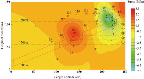
Figure 11.
Contour of stress increment of filling mining to the fifth sublevel.
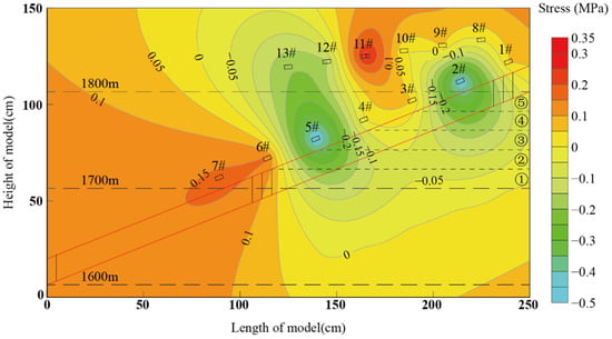
Figure 12.
Contour of stress increment of fill mass excavation to the second sublevel.
When the displacement and stress of the rock mass are stable, the backfill mass is excavated downward from the fifth sublevel to compare and analyze the stress distribution state of the rock formation. Figure 12 shows the stress increment after excavating the second sublevel backfill mass. As noted from the figure, due to the increase in the exposed area of the goaf after the excavation of the backfill mass, the stress in the near-field area of the overlying strata decreases. The essence is that the roof loses its supporting function and deforms downward to provide pressure relief. The roof then collapsed, and the stress value of the 11# pressure sensor on the caving arch increased, as did the stress values of the 1#, 6#, and 7# pressure sensors at both ends of the goaf. It demonstrates that strata stress is relocated to the top of the caving arch and the adjacent rock mass on both sides of the arch, and backfill excavation significantly impacts the surrounding rock stress field.
In summary, backfill has performed a controllable supporting function for the overlying strata as the filler’s bearing capacity has improved. The action of the overlying strata is gradually transmitted to the backfill and the surrounding rock of the goaf. The backfill mass improves the stress status and decreases the stress concentration of the surrounding rock, which contributes to the stability of the overlying strata.
6. Conclusions
- (1)
- The loads from the overlying strata are transferred to the dense fill mass and the surrounding rock as backfill mining is employed, and the stress in the near-field area of the surrounding rock increases and stabilizes gradually. The backfill mass improves the stress distribution state and reduces the stress concentration of the surrounding rock, which is conducive to preventing the progressive damage of the overlying strata;
- (2)
- The displacement and movement range of the overlying strata steadily increases as the backfill is excavated. A large-scale collapse occurred in the roof of the goaf due to the exposed area being too large and exceeding its limit. The caving range along the inclined direction of the ore body is 105 m, the vertical caving height is roughly 25–45 m, and the surface subsidence value is about 0.8–1.2 m. It poses a considerable threat to the safety of underground mining and surface infrastructure;
- (3)
- The stress of the overlying strata is transferred toward the surrounding rock mass above and on both sides of the caving arch after roof caving. The backfill excavation significantly influences the surrounding rock stress field.
Author Contributions
Conceptualization, W.L. and Y.Z.; methodology, W.L. and Y.Z.; validation, K.L., J.L., and M.X.; formal analysis, W.L.; investigation, W.L. and F.F.; resources, F.F.; data curation, W.L. and Y.Z.; writing—original draft preparation, W.L.; writing—review and editing, K.L. and J.L.; visualization, Y.Z. and F.F.; supervision, K.L., J.L., and M.X.; project administration, W.L. and M.X.; funding acquisition, W.L. and M.X. All authors have read and agreed to the published version of the manuscript.
Funding
This research was funded by the Guizhou Provincial Science and Technology Projects (No. QKHZC [2021] General 407), the New Talent Training Project of Guizhou Institute of Technology (No. GZLGXM-29), the National Natural Science Foundation of China (No. 52104123), and the China Scholarship Council (No. 202108525011).
Data Availability Statement
All data supporting the findings in this study are available from the corresponding author on reasonable request.
Conflicts of Interest
The authors declare that they have no known conflicts of interest that could influence the work reported in this paper.
References
- Sheshpari, M. Failures in Backfilled Stopes and Barricades in Underground Mines. Electron. J. Geotech. Eng. 2015, 20, 191–212. [Google Scholar]
- Sheshpari, M. A Review of Underground Mine Backfilling Methods with Emphasis on Cemented Paste Backfill. Electron. J. Geotech. Eng. 2015, 20, 5183–5208. [Google Scholar]
- Zhang, J.; Zhang, Q.; Sun, Q.; Gao, R.; Germain, D.; Abro, S. Surface subsidence control theory and application to backfill coal mining technology. Environ. Earth Sci. 2015, 74, 1439–1448. [Google Scholar] [CrossRef]
- Chen, S.; Yin, D.; Cao, F.; Liu, Y.; Ren, K. An overview of integrated surface subsidence-reducing technology in mining areas of China. Nat. Hazards 2015, 81, 1129–1145. [Google Scholar] [CrossRef]
- Alehossein, H.; Shen, B.; Qin, Z. Backfill grouting for mining subsidence prevention. In Proceedings of the 2021 Resource Operators Conference, Wollongong, Australia, 10–12 February 2021. [Google Scholar]
- Qi, C.; Fourie, A. Numerical Investigation of the Stress Distribution in Backfilled Stopes Considering Creep Behaviour of Rock Mass. Rock Mech. Rock Eng. 2019, 52, 3353–3371. [Google Scholar] [CrossRef]
- Falaknaz, N.; Aubertin, M.; Li, L. Numerical investigation of the geomechanical response of adjacent backfilled stopes. Can. Geotech. J. 2015, 52, 1507–1525. [Google Scholar] [CrossRef]
- Aubertin, M.; Li, L.; Arnoldi, S.; Belem, T.; Bussière, B.; Benzaazoua, M.; Simon, R. Interaction between backfill and rock mass in narrow stopes. Soil Rock Am. 2003, 1, 1157–1164. [Google Scholar]
- Hassani, F.P.; Mortazavi, A.; Shabani, M. An investigation of mechanisms involved in backfill-rock mass behaviour in narrow vein mining. J. S. Afr. Inst. Min. Metall. 2008, 108, 463–472. [Google Scholar]
- Jahanbakhshzadeh, A.; Aubertin, M.; Li, L. A New Analytical Solution for the Stress State in Inclined Backfilled Mine Stopes. Geotech. Geol. Eng. 2017, 35, 1151–1167. [Google Scholar] [CrossRef]
- Cui, L.; Fall, M. A coupled thermo–hydro-mechanical–chemical model for underground cemented tailings backfill. Tunn. Undergr. Space Technol. 2015, 50, 396–414. [Google Scholar] [CrossRef]
- Cui, L.; Fall, M. Multiphysics modeling of arching effects in fill mass. Comput. Geotech. 2017, 83, 114–131. [Google Scholar] [CrossRef]
- You, X.; Ren, F.Y.; He, R.X.; Ding, H.X. Research on compressive strength of cemented filling body in subsequent filling at the stage of open stope. J. Min. Saf. Eng. 2017, 34, 163–169. [Google Scholar] [CrossRef]
- Sobhi, M.A.; Li, L. Numerical investigation of the stresses in backfilled stopes overlying a sill mat. J. Rock Mech. Geotech. Eng. 2017, 9, 490–501. [Google Scholar] [CrossRef]
- Sobhi, M.A.; Li, L.; Aubertin, M. Numerical investigation of earth pressure coefficient along central line of backfilled stopes. Can. Geotech. J. 2017, 54, 138–145. [Google Scholar] [CrossRef]
- Fang, K.; Cui, L.; Fall, M. A coupled chemo-elastic cohesive zone model for backfill-rock interface. Comput. Geotech. 2020, 125, 103666. [Google Scholar] [CrossRef]
- Fang, K.; Fall, M.; Cui, L. Thermo-chemo-mechanical cohesive zone model for cemented paste backfill-rock interface. Eng. Fract. Mech. 2021, 244, 107546. [Google Scholar] [CrossRef]
- Yu, X.; Xiong, Z.; Song, W.; Chu, L.; Tan, Y. study on dynamic stability of mine pillar and filling body in high-stage subsequent cemented filling method. Min. Res. Dev. 2022, 42, 26–31. [Google Scholar] [CrossRef]
- Tan, Y.; Yu, X.; Song, W.; Wang, H.; Cao, S. Experimental study on combined pressure-bearing mechanism of filling body and surrounding rock. J. Min. Saf. Eng. 2018, 35, 1071–1076. [Google Scholar] [CrossRef]
- Yu, S.; Yang, X.; Dong, K.; Xie, L.; Sun, X.; Guo, L. Space-time rule of the control action of filling body for the movement of surrounding rock in method of the delayed filling open stoping. J. Min. Saf. Eng. 2014, 31, 430–434. [Google Scholar] [CrossRef]
- Wang, Q.; He, Y.; Yang, F.; Wu, M.; Yao, N. Study on Stress Distribution and Movement Law of Overburden Deformation of Waste Rock Tailings Filling Structure. Met. Mine 2022, 128–135, 756–765. [Google Scholar]
- Yao, N.; Li, P.; Wang, Q.; Ye, Y.; Sun, L.; Deng, X.; Zhang, Y. Synergetic Mining Technology for Strip-filling Zone of Gently Inclined Phosphate Deposits under Complex Terrain. Met. Mine 2020, 50, 109–116. [Google Scholar] [CrossRef]
- Zhu, X.; Guo, G.; Liu, H.; Yang, X. Surface subsidence prediction method of backfill-strip mining in coal mining. Bull. Eng. Geol. Environ. 2019, 78, 6235–6248. [Google Scholar] [CrossRef]
- Zha, J.; Guo, G.; Feng, W.; Wang, Q. Mining subsidence control by solid backfilling under buildings. Trans. Nonferrous Met. Soc. China 2011, 21, s670–s674. [Google Scholar] [CrossRef]
- Bai, E.; Guo, W.; Tan, Y.; Yang, D. The analysis and application of granular backfill material to reduce surface subsidence in China’s northwest coal mining area. PLoS ONE 2018, 13, e0201112. [Google Scholar] [CrossRef]
- JIA, L. Experimental study on failure characteristics of strata with different filling rates in longwall filling mining. Coal Sci. Technol. 2019, 47, 197–202. [Google Scholar] [CrossRef]
- Adach-Pawelus, K.; Pawelus, D. Application of Hydraulic Backfill for Rockburst Prevention in the Mining Field with Remnant in the Polish Underground Copper Mines. Energies 2021, 14, 3869. [Google Scholar] [CrossRef]
- Sivakugan, N.; Veenstra, R.; Naguleswaran, N. Underground Mine Backfilling in Australia Using Paste Fills and Hydraulic Fills. Int. J. Geosynth. Ground Eng. 2015, 1, 18. [Google Scholar] [CrossRef]
- Karian, T.; Shimada, H.; Sasaoka, T.; Wahyudi, S.; Qian, D.; Sulistianto, B. Countermeasure Method for Stope Instability in Crown Pillar Area of Cut and Fill Underground Mine. Int. J. Geosci. 2016, 7, 280–300. [Google Scholar] [CrossRef]
- Zhou, N.; Zhang, J.; Yan, H.; Li, M. Deformation Behavior of Hard Roofs in Solid Backfill Coal Mining Using Physical Models. Energies 2017, 10, 557. [Google Scholar] [CrossRef]
- Zuev, B.Y.; Zubov, V.P.; Fedorov, A.S. Application prospects for models of equivalent materials in studies of geomechanical processes in underground mining of solid minerals. Eurasian Min. 2019, 1, 8–12. [Google Scholar] [CrossRef]
- Ghabraie, B.; Ren, G.; Smith, J.; Holden, L. Application of 3D laser scanner, optical transducers and digital image processing techniques in physical modelling of mining-related strata movement. Int. J. Rock Mech. Min. Sci. 2015, 80, 219–230. [Google Scholar] [CrossRef]
- Sun, X.; Zhao, C.; Zhang, Y.; Chen, F.; Zhang, S.; Zhang, K. Physical model test and numerical simulation on the failure mechanism of the roadway in layered soft rocks. Int. J. Min. Sci. Technol. 2021, 31, 291–302. [Google Scholar] [CrossRef]
- Liang, W.; Zhao, W. experimental study on deformation and failure rule of overlying strata in Hongnipo copper mine. China Min. Mag. 2020, 29, 110–116. [Google Scholar]
- Rankine, R.; Pacheco, M.; Sivakugan, N. Underground Mining with Backfills. Soils Rocks 2007, 30, 93–101. [Google Scholar] [CrossRef]
- Wang, F.; Jiang, B.; Chen, S.; Ren, M. Surface collapse control under thick unconsolidated layers by backfilling strip mining in coal mines. Int. J. Rock Mech. Min. Sci. 2019, 113, 268–277. [Google Scholar] [CrossRef]
- Zhao, X.; Fourie, A.; Qi, C. Mechanics and safety issues in tailing-based backfill: A review. Int. J. Miner. Metall. Mater. 2020, 27, 1165–1178. [Google Scholar] [CrossRef]
Publisher’s Note: MDPI stays neutral with regard to jurisdictional claims in published maps and institutional affiliations. |
© 2022 by the authors. Licensee MDPI, Basel, Switzerland. This article is an open access article distributed under the terms and conditions of the Creative Commons Attribution (CC BY) license (https://creativecommons.org/licenses/by/4.0/).