Abstract
Accurately distinguishing the stability of the residual coal pillars formed by the room-and-pillar mining method is significant for the safe mining of adjacent coal seams. In this study, the correlation between the rapid decrease in vertical stress and the connectivity of the internal dissipative energy core during the instability of coal pillars is revealed. Then, a new method for distinguishing the stability of coal pillars based on the above correlation is proposed, overcoming the shortcomings of previous studies that only used the plastic zone range to determine the stability of coal pillars. Based on this discriminant index and simulation method, the mechanism of residual coal pillar failure as well as the dynamic instability and expansion characteristics of multi-pillars have been revealed. The engineering method of grouting and filling to enhance the bearing capacity of coal pillars is proposed, and an in-depth study is conducted on the improvement effect of different strength filling materials on the bearing capacity of coal pillars. And the reasonable filling body strength is determined to be greater than 3MPa. The new discrimination method has important guiding significance for the analysis of coal pillar stability and the formulation of safety protection technical measures on engineering scales.
1. Introduction
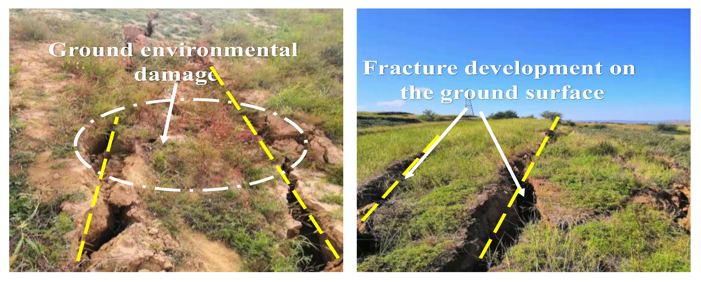
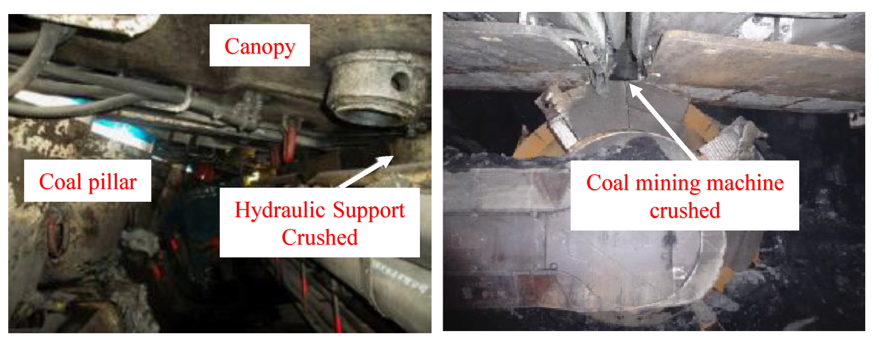
Coal has been one of the most important sources of primary energy, together with oil and natural gas, for many decades now. Approximately one-third of the world’s energy and 40% of electricity is generated from coal, which will remain an important part of the global energy mix in the medium to long term [1,2]. During the early extraction of coal resources, the room-and-pillar mining method has become one of the most common coal mining methods due to its simple excavation equipment and mining process. However, the residual coal pillars, under the comprehensive influence of long-term overlying strata pressure, mine water erosion, and the disturbance of adjacent coal seam excavation, may be damaged and result in ground collapse, building damage, and underground rock burst and support crushed accidents [3,4], which have become a severe challenge for environmental protection and safe mining. In China, the northwest mining area is one of the highest coal-producing areas, and the room-and-pillar mining method was widely adopted in the early years, which resulted in numerous residual coal pillars in the goaf. Ground collapse and support crushed accidents in longwall mining of adjacent working faces are caused by the instability of the residual coal pillars, as shown in Figure 1 and Figure 2. In fact, it is not just in China, as one study also showed that over the past decade, rib falls have resulted in 12 fatalities, representing 28% of ground fall fatalities in the United States’ underground coal mines. Nine of these twelve fatalities (75%) occurred in room-and-pillar mines [5], causing serious casualties and economic losses [6]. Therefore, an accurate assessment of coal pillar instability and its failure characteristics and an exploration of scientific mining methods that can be employed to prevent coal pillar failure are crucial for the safe mining of adjacent coal seams.
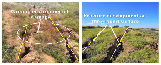
Figure 1.
Environmental damage caused by coal pillar failure in room-and-pillar mining goaf.
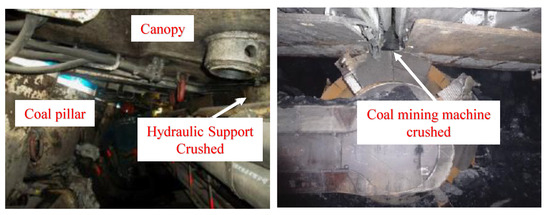
Figure 2.
Manifestation of strong mineral pressure in longwall mining of adjacent coal seams in a room-and-pillar goaf [7,8].
A great amount of effective research about single residual coal pillars has been conducted on the safety factor [9,10], design criteria based on overloading [11], failure mechanisms [12,13,14], failure characteristics [9], and ultimate bearing capacity [15]. In fact, most of the residual coal pillars in the room-and-pillar type of goaf exist in the form of coal pillar clusters; some pillars with a high factor of safety also fail without any precursor [16]. Cascading pillar failure is usually caused when one pillar fails and the additional load is transferred to overload the adjacent pillars [11,17]. Therefore, accurately identifying the first coal pillar to fail, grasping the instability and expansion law of the coal pillar clusters caused by this, and formulating safety mining guarantee measures are of great significance for the recovery of adjacent coal seam resources.
With the help of numerical simulation, a large amount of research has been conducted on the impact of mining-induced stress of adjacent coal seams on the stability of coal pillar clusters, as well as the impact of the instability of coal pillar clusters on the safety of adjacent mining working faces, including the effect of spatial distribution between the upper and lower coal pillars on the stability of double-seam mining [18], the stress distribution of the floor under the residual coal pillar clusters [19], hydraulic fracturing and pressure relief [20], the instability and expansion process of coal pillar clusters [21,22,23], the fatigue damage mechanism and bearing characteristics of multiple coal pillars [17,24], the roof collapse process caused by the instability of the coal pillar cluster [25], movement characteristics of the main roof articulated blocks [26,27], crushed supports [8,28], and the coupling effect of water immersion and mining stress on the stability of coal pillar clusters [29,30]. The above research provides an important reference for exploring methods for distinguishing the stability of multiple coal pillars and conducting in-depth research on the instability and expansion characteristics of coal pillar clusters in this article.
However, the distinction of which coal pillar in the coal pillar cluster is the first to fail and lose stability is still based on the distinguishing index of single coal pillar instability, such as the ultimate strength [31,32,33] and plastic zone proportion ratio [34,35,36]. The variation law of internal stress and energy of each coal pillar in the whole process from local damage, crack extension, and the main crack penetration to the overall failure has not been considered under the action of mining stress disturbance in the adjacent coal seam. More importantly, in numerical simulation, a large amount of literature has adopted the distribution range or ratio of plastic zones to distinguish the stability of coal pillars [34,35,36], i.e., the coal pillar is considered to be destabilized when the ratio of plastic deformation units to the total number of units in the coal pillar exceeds a critical value. However, the concrete value of this critical value is often obtained empirically, such as 69% in the literature [23,36], as well as other works taking the width of the elastic core of the coal pillar to be no less than two times the mining height as the critical condition for instability [29,37], or some works taking the connectivity of the plastic zone as the criterion of coal pillar instability [38]. Numerous and highly diverse indexes make it difficult to accurately distinguish whether a single pillar is destabilized or not and to distinguish the first pillar to be destabilized in a multi-pillar system. In fact, the full stress–strain curves of the coal rock samples also indicate that the yield strength is about two-thirds of the ultimate strength [39,40], which implies that even though all of the units in the coal pillar exceeded the yield strength and plastic deformation occurred, as long as the vertical stresses did not exceed the ultimate strength, the coal pillar would not be destabilized and would still possess a good bearing capacity. It can be seen that the distribution range of the plastic zone, the ratio of the plastic zone, and the connectivity of the plastic zone are not equivalent to whether the coal pillar is destabilized (loss of bearing capacity), i.e., a high ratio of the plastic zone or even the overall plastic damage of the coal pillar does not mean that the coal pillar will be destabilized. The above shows that there is a big defect in evaluating the stability of coal pillars only by plastic zone.
In fact, the support force of the coal pillar to the roof strata reflects the bearing state of the coal pillar very well. When the residual coal pillar is affected by the mining of the adjacent working face, the reduction in the support force of the coal pillar may be due to the pressure relief caused by the peak value of mining-induced stress pushing through (at this time, the coal pillar is not destabilized), and on the other hand, the superposition of mining-induced stress causes the coal pillar to be overloaded and destabilized, so the bearing capacity is weakened. Furthermore, plastic deformation and destabilization are energy-driven external manifestations, and the dissipative energy core is not connected when the support force is reduced due to pressure relief, whereas the dissipative energy core appears to be connected when the bearing capacity is weakened due to destabilization of the coal pillar. The above rules are precisely the new discoveries and innovations of this article. From this, it can be seen that using vertical stress drop and dissipative energy core connectivity as indicators of coal pillar stability is more accurate.
Therefore, a program is developed to track the evolving process of dissipated energy in coal pillars, and followed by the dynamic evolution characteristics of the dissipated energy and vertical stress of coal pillars under the effect of mining-induced stress of adjacent coal mining working faces. A good consistency between the vertical stress drop and the connectivity of the dissipative energy core when the coal pillar undergoes failure and instability is found. Based on this, a numerical simulation discriminant criterion that is more suitable for evaluating the stability of coal pillars compared to the original method is proposed, that is, “vertical stress drop (lower than the initial vertical stress) + connectivity of the dissipative energy core” can be used to accurately determine which coal pillar in the coal pillar clusters will lose stability first, which is crucial for determining the weak links of the coal pillar cluster and developing corresponding reinforcement measures. The engineering practice of grouting and filling to reinforce the coal pillar cluster has been carried out, and the reasonable filling strength is 3 MPa. The bearing capacity of the coal pillar has been greatly improved, and the No. 6107 working face has achieved safe mining.
2. Engineering Geological Conditions
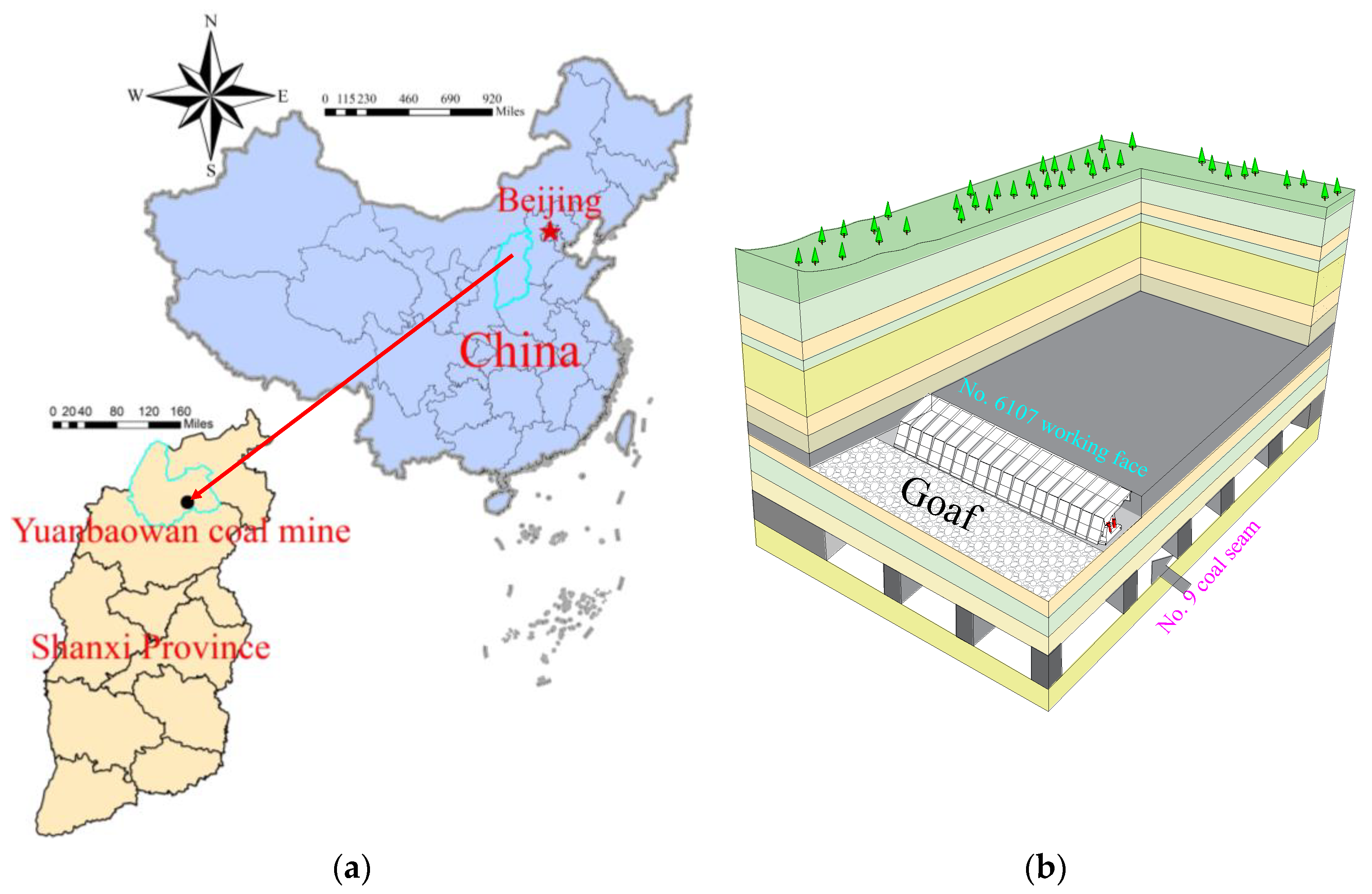
Yuanbaowan coal mine is located in Shuozhou City (Shanxi Province) in the territory of Shanyin County (Figure 3a). At present, the No. 6 coal seam has an average depth of 150 m and is mainly mined in the Yuanbaowan coal mine; it is located above the No. 9 coal seam, and the average thickness of the rock strata between the seams is approximately 15 m. The advancing direction of the No. 6107 working face has a cumulative length of 240 m and is located directly above the room-and-pillar type of goaf of the No. 9 seam, and its working face faces the stirrups in this area. The length and width of the goaf in the No. 9 coal seam are approximately 25–50 m and 5–15 m, respectively, and the height of the residual coal pillar is 5–9 m (average 8 m). The relative position of the No. 6107 working face and its underlying room-and-pillar mining goaf are shown in Figure 3b. The inclination angle of the No. 6 coal seam is 4–8° (average 6°), and the room-and-pillar mining goaf of the No. 9 coal seam below the No. 6107 working face has a slightly lower coal seam inclination angle (average of approximately 3°).
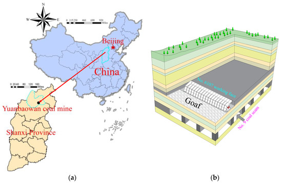
Figure 3.
(a) Geographic location of the studied coal seams. (b) Location of the No. 6107 working face relative to the room-and-pillar mining goaf below it.
3. Construction of an Energy Dissipation Model Characterizing the Gradual Failure of Coal Pillars
3.1. Construction of Numerical Model
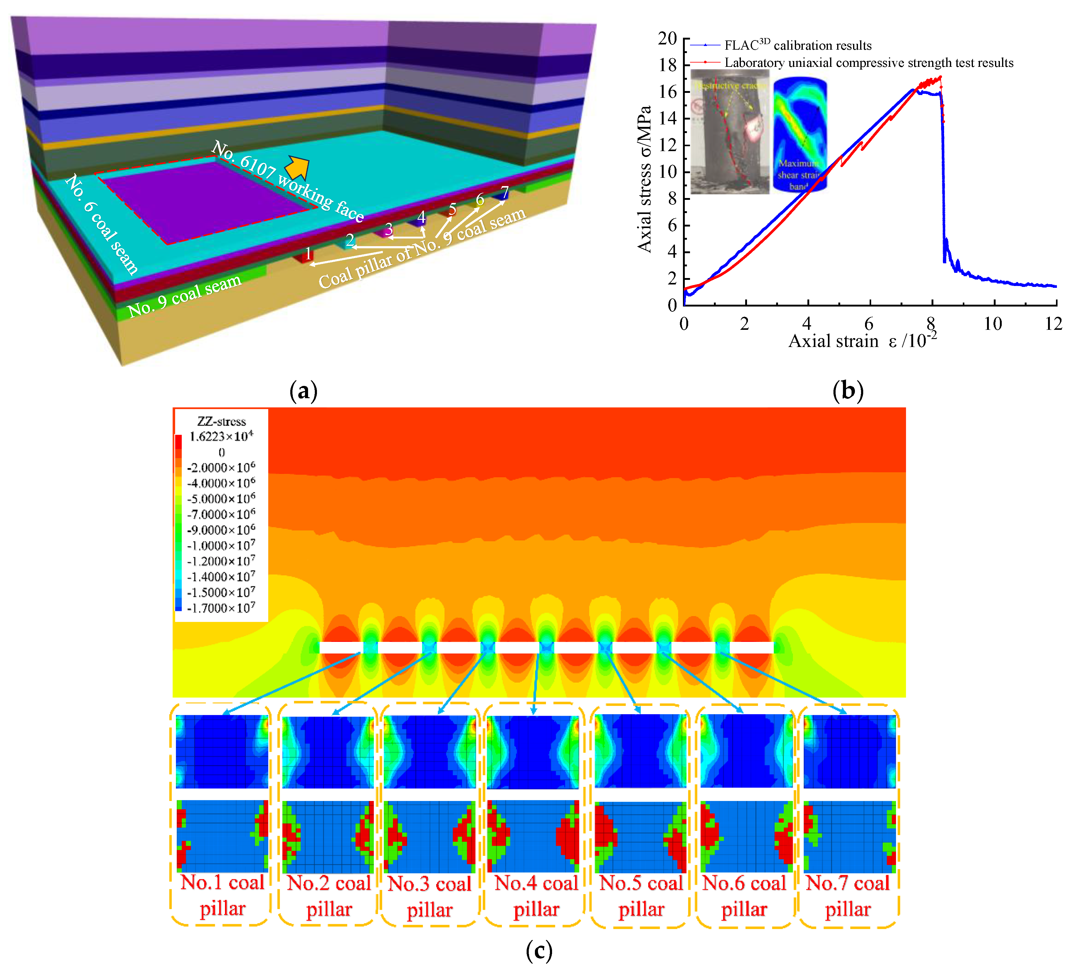
Based on the aforementioned project overview, a FLAC3D numerical simulation model was constructed to study the stability of the bottom coal pillar in the No. 6107 working face safety mining, as shown in Figure 4a, and the physical and mechanical parameters of overlying strata and coal seams are shown in Table 1. The model mainly includes coal seams No. 6 and 9 and their top and bottom strata, with displacement confinement on the periphery and bottom boundaries, and free boundaries on the upper part. To study the failure and damage characteristics of the coal pillars in the No. 9 coal seam (below the No. 6 coal seam) under mining perturbation, the No. 9 coal seam is mined first in accordance with the actual mining sequence. After the calculation is stabilized to form a room-and-pillar mining goaf, the No. 6 coal seam is then mined by stirrups and longwall mining. To accurately characterize the evolution of the bearing capacity of the bottom coal pillar and the failure and damage characteristics, the No. 9 coal seam in the model adopts the strain softening model. In this respect, samples were taken from the No. 9 coal seam below the No. 6107 working face in the Yuanbaowan coal mine, and the physio-mechanical parameters were obtained in a laboratory to calibrate the parameters of the No. 9 coal seam for the numerical simulation. The results are shown in Figure 4b.

Figure 4.
(a) 3D model of No. 6107 mining working face. (b) Parameter calibration of No. 9 coal seam. (c) Stability of the bottom coal pillars before mining of No. 6107 working face.

Table 1.
Physical and mechanical parameters of rocks and coal.
After room-and-pillar mining of the No. 9 coal seam and before mining of the No. 6107 working face, although the left and right gangs of the bottom coal pillars showed different degrees of plasticity and energy dissipation areas, the proportion of elastic core in each coal pillar was far more than 31%, which means that the bottom coal pillars were in a stable state before mining of the No. 6107 working face, as shown in Figure 4c.
3.2. Development of FLAC3D Energy Dissipation Models
In the stirrup mining process of the No. 6107 working face, gradual failure of the bottom coal pillar under the effect of re-mining stress perturbation from the overlying working face is often accompanied by the evolution of energy, rupture, and destruction. The overall instability of the coal and rock mass is an external behavior induced by the intrinsic energy drive, and the deformation and destruction can be regarded as a result of the conversion of different forms of energy into each other [41,42]. The energy dissipation model of the coal and rock mass could be used to accurately locate the main area of damage in the engineered rock mass, quantify the degree of damage that the coal and rock mass underwent, and assess the stability of a coal and rock mass with post-peak damage. Therefore, to quantitatively characterize the damage degree of each subregion of a coal pillar under the effect of mining perturbation, and thus accurately locate the main area of damage, with the aim of analyzing the destabilization form of the coal pillar, we developed a Fish program to characterize the real-time evolution and dynamic distribution of internal energy throughout the whole deformation and damage process within the coal and rock mass, enabling the secondary development of the FLAC3D (5.01, Itasca Consulting Group, Minneapolis, MN, USA) strain softening model.
The model adopts an explicit difference algorithm, which first determines the interval time step, , of the operation while capturing the initial stress value, , and the stress state is solved at each moment in real time during the operation. In this solving process, the principal stresses, , , and , and the corresponding principal strain increments, , , and , of the target unit are first captured, where
in which is the elastic strain increment and is the plastic strain increment.
According to the generalized Hooke’s law, the relationship between each principal stress increment and the elastic strain increment of the unit body is as follows:
where and are the material constants defined according to the bulk modulus, , and the shear modulus, , where , . By solving Equation (2), the elastic strain increment of the unit body in each direction is expressed as follows:
The Mohr–Coulomb based strain softening model has non-associative shear and associative tension flow laws, whereas the plastic yielding flow law has a certain form, as follows:
where is the plastic multiplication factor, and is the potential function. The plastic strain increment under shear yielding [43] can be expressed as follows:
where is cohesion, is the internal friction angle, , and is the dilation angle, .
The plastic strain increment of the unit when tension yielding occurs [43] can be expressed as follows:
where is the tensile strength.
Therefore, we could capture the principal stress and principal strain increments of the unit at each moment through the zone variables and zone field data variables of the Fish program, respectively. By doing so, we obtain the elastic strain increments and plastic strain increments of the unit through the solution which were used to solve the total energy of the unit and its elastic and dissipative energies.
In calculating the unit energy, the system performs a cycle every time step, and each cycle performs a full scan of the unit and solves for the energy of the unit. When the target unit was at time and it corresponded to the cycle, the total energy increment of the unit at time steps to was expressed as follows:
where is the total energy increment of the unit of time step from to and is the average value of the unit principal stresses from to , which could be expressed by the principal stress at time and the principal stress at time , where ( = 1, 2, 3).
Therefore, the total energy of the target unit at the moment is equal to the accumulation of the total energy increment of cycles. In this respect, the idea of the integral operation is utilized to solve the total energy of the unit.
Existing studies [41] have calculated the elastic strain of a unit by capturing the principal stress of the unit and its given elastic modulus, and they have then solved the elastic strain energy of the unit. However, there are large differences in the values of the elastic modulus at various stages during the whole process of deformation and damage of coal and rock mass. Therefore, in this study, the elastic energy accumulation of the target unit was calculated by capturing the principal stress, , of the target unit and solving the elastic strain, , of the target unit as follows:
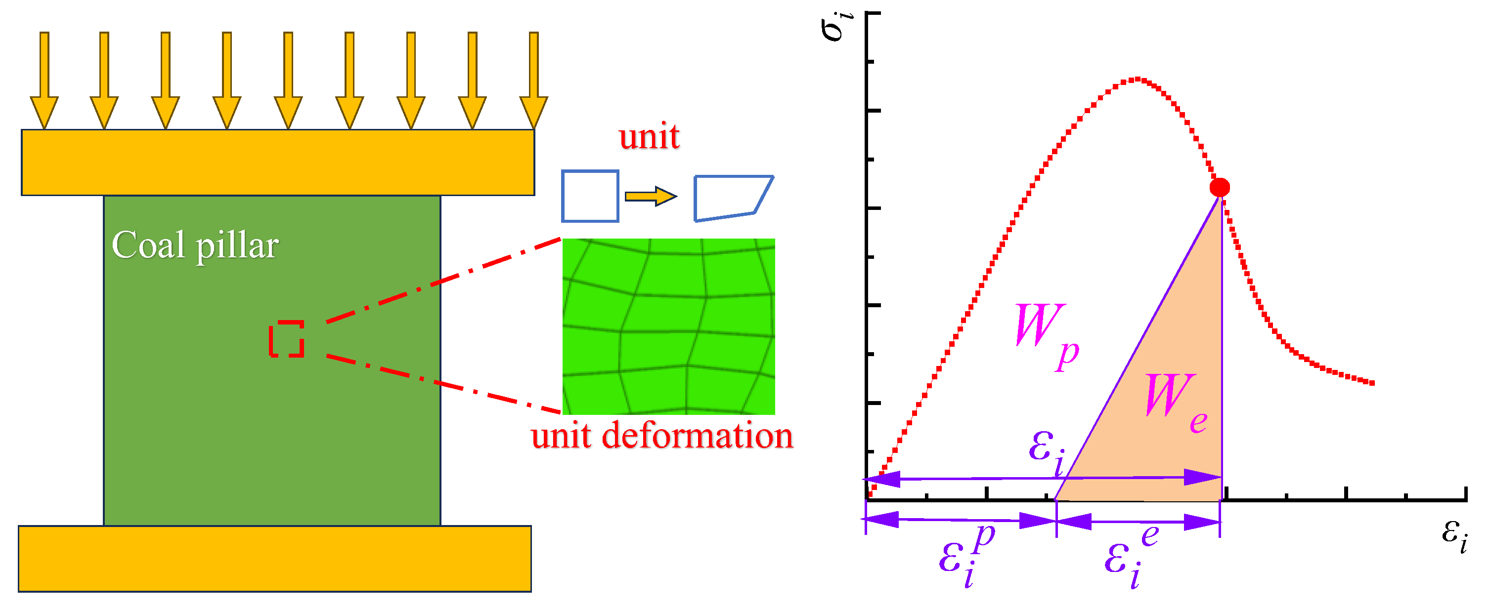
In addition, the dissipated energy of the target unit (Figure 5) is calculated as follows:
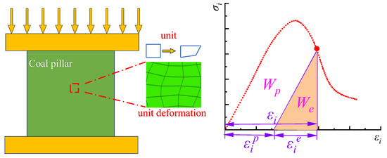
Figure 5.
Schematic representation of the calculation of the elastic and dissipated energy of the unit.
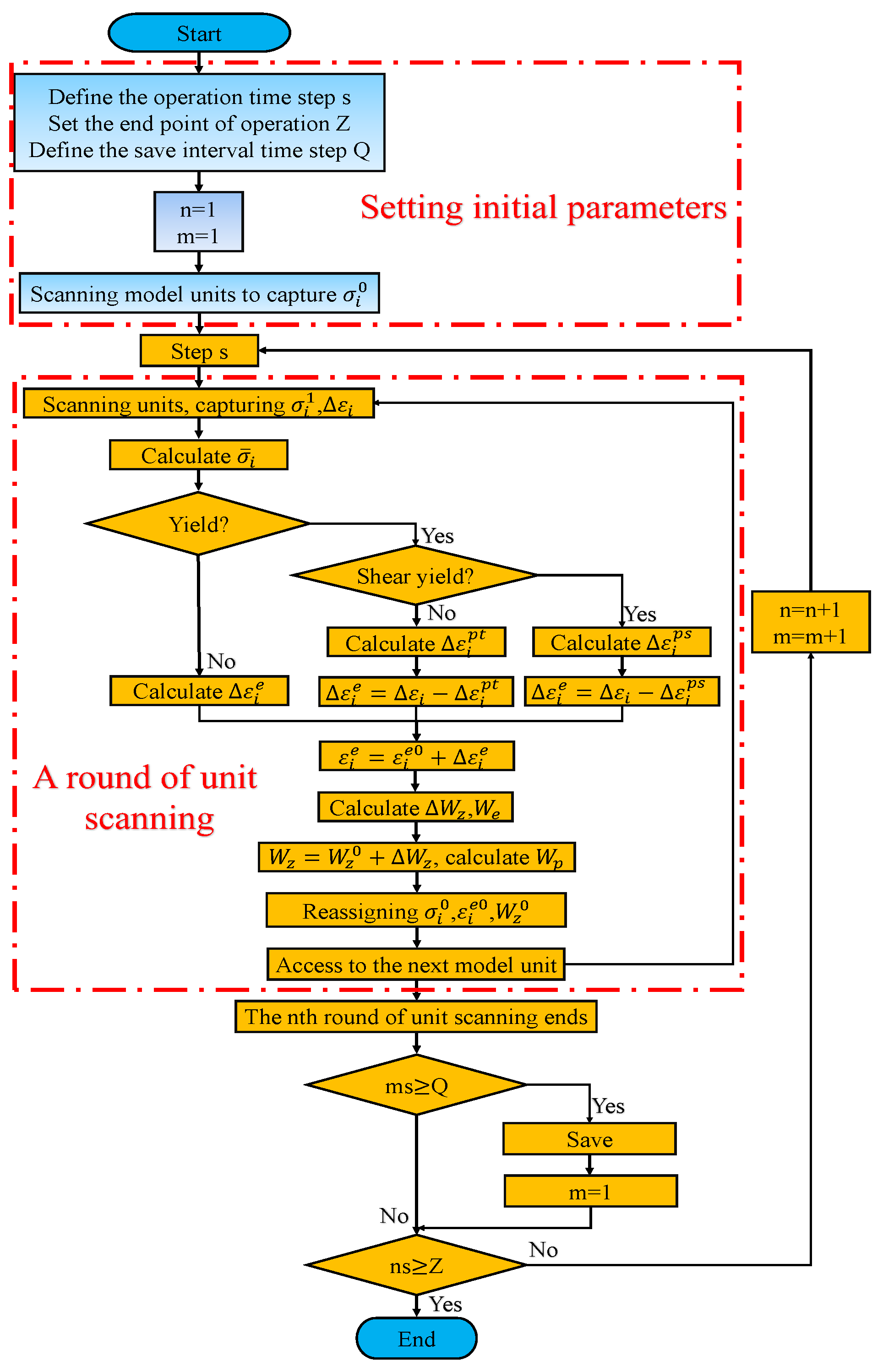
When the total energy, elastic strain, and dissipation energies located in each subregion(unit) inside the coal pillar are quantified respectively, the energy distribution law of the whole coal pillar can be obtained. Therefore, based on the above theoretical analysis, this study used Fish language to construct a model of energy dynamic distribution and its real-time evolution law, and the specific development process is shown in Figure 6. In the simulation, a cycle was performed every s time steps, and a full scan of the unit was performed in each cycle. After visiting each target unit in each scan, the primary stress, , and the primary strain increment, , of the unit were obtained, and the elastic strain increment, , and plastic strain increment, , of the unit and the total energy increment, , of the unit were solved. Simultaneously, the relevant variables that characterized the total stress, strain, and the total energy of the unit were re-assigned.

Figure 6.
Fish calculation program for the dissipation energy of coal and rock mass rupture under mining action in the No. 6107 working face.
3.3. Coal Pillar Destruction and Failure Criteria
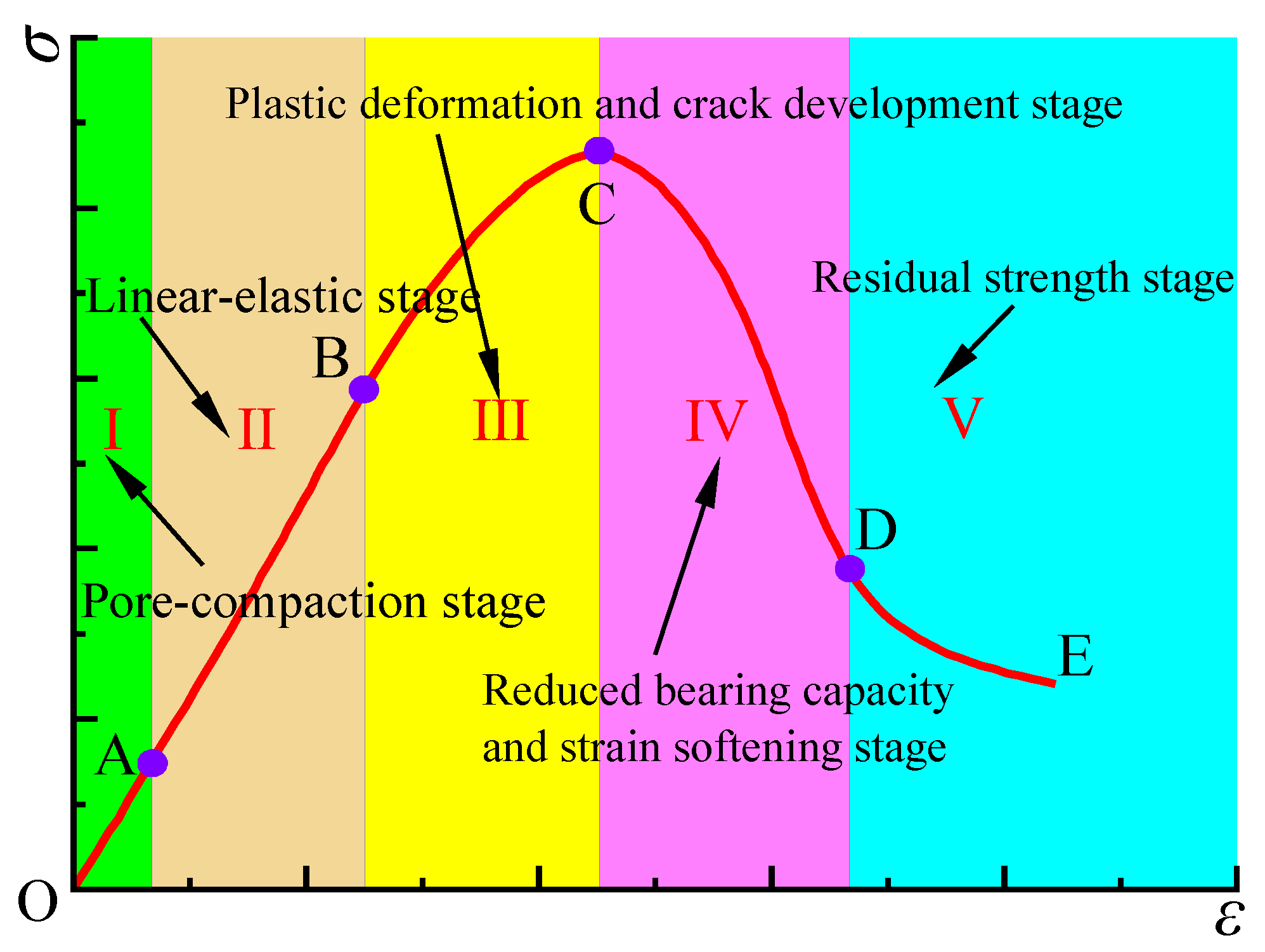
During the advancing process of the No.6107 working face, if the bottom coal pillar fails and destabilizes under the effect of a large front abutment pressure, it will lead to the loss of its bearing capacity and induce destabilization of the adjacent coal pillars, which will seriously threaten the safe mining of the overlying working face. Therefore, there is a lack of quantitative indexes on how to accurately judge and capture the timing of destabilization or loss of bearing capacity of coal pillars under mining disturbance, which makes it difficult to assess the stability of coal pillars and accurately prevent and control secondary disasters induced by coal pillar destabilization. In the existing studies, whether the coal pillar is destabilized or not is determined by analyzing whether the plastic zone inside the coal pillar is connected or whether the proportion of elastic core reaches a certain index; however, according to the full stress–strain curve of coal rock samples in the rock mechanics (Figure 7), the deformation of the rock is divided into five phases, i.e., respectively, the OA section: pore compression stage, the AB section: linear elastic stage, the BC section: plastic deformation and crack development stage, the CD section: reduced bearing capacity and strain softening stage, and the DE section: residual strength stage [39,44]. Point B is the turning point of coal and rock mass from elastic to plastic, i.e., the yield point; therefore, in the BC section, the rock mass is already in the stage of plastic deformation. At this time, the rock mass has not undergone destructive failure, and there is still a strong bearing capacity until it reaches the peak strength of the rock mass (point C), and its load-bearing capacity gradually deteriorates until the internal cracks converge to form a macroscopic fracture surface, which leads to the destructive failure of the rock mass. Therefore, it is insufficient to judge whether the coal pillar failure occurs only by the index of the plasticity zone.
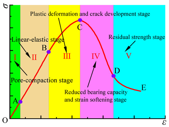
Figure 7.
Characteristics of phases occurring over a typical full stress–strain curve.
At the same time, the bearing capacity of the coal pillar is greatly weakened or lost when the coal pillar fails, so the bearing state of the coal pillar can reflect its failure characteristics, and the support force of the coal pillar on the roof strata can well characterize the bearing state of the coal pillar. However, the decrease in the support force of the coal pillar on the overlying strata (lower than the initial vertical stress) under the effect of the mining stress perturbation in the adjacent seams may be partly due to the pressure relief caused by the pushing through of the peak mining stress (at this time, the coal pillar is not destabilized), and partly due to the destabilization of the coal pillar caused by the superimposition of the mining stresses, resulting in the overloading of the coal pillar. Therefore, it is necessary to accurately and quantitatively characterize the causes of the failure of the bottom coal pillar during re-mining stress disturbances and to accurately study the gradual failure and destruction process of the coal pillar in the form of local damage, crack extension, the main crack penetration, and the overall failure, and in turn, accurately distinguishing between the two causes of vertical stress drop mentioned above is important for accurately distinguishing the failure of the coal pillar.
In view of this, the numerical simulation method based on the energy dissipation program constructed in this paper can accurately capture the development and formation process of the main fracture surface inside the coal pillar, which has great advantages in revealing the causes of coal pillar failure in the microscopic aspect, thus effectively compensating for the above shortcomings of distinguishing the failure of coal pillars only by the support stress drop. In this study, the idea that “the vertical stress is lower than the initial stress + the dissipative energy core is connected” is proposed, from macroscopic–microscopic perspectives, as the critical condition for the transition from the damage to the failure stage of the coal pillar during the superposition of mining stress (i.e., the index of the overall stability of the coal pillars). It provides a more effective method for accurately distinguishing the failure of coal pillars in single-pillar systems as well as the first failed pillars in multi-pillar systems under the effect of mining stress perturbation and for characterizing the failure propagation of the subsequent pillars.
4. Numerical Simulation of Dynamic Failure Process of Multi-Coal Pillars
4.1. Law of Evolution of Coal Pillars’ Bearing Capacity under Stress Disturbance of Re-Mining
Ensuring the stability of the bottom coal pillar under mining disturbance is key to achieving the safe mining of the No. 6107 working face. During the advancement of the No. 6107 working face, the coal pillar below the area in which the concentration of the front abutment pressure was formed was subjected to high vertical stress. This pillar could easily fail due to the loss of its load-bearing capacity, which would substantially reduce its internal vertical stress. Therefore, in the simulation process, the measuring points and lines were arranged in the middle of each of the coal pillars in the No. 9 coal seam (as shown in Figure 8) to monitor the distribution law and dynamic evolution characteristics of the vertical stress of the bottom coal pillar during advancement of the No. 6107 working face. The law of dynamic change in the vertical stress of each bottom coal pillar during the advancement of the working face is shown in Figure 9.
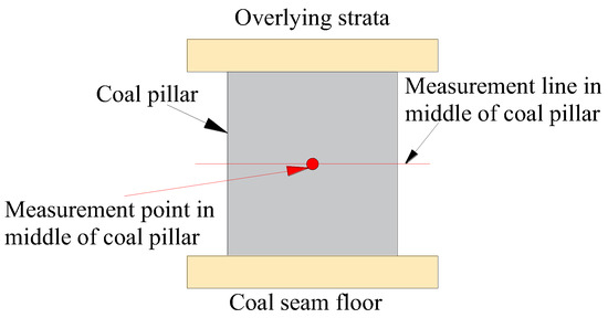
Figure 8.
Locations of measurement points and lines in the coal pillar in the numerical model.
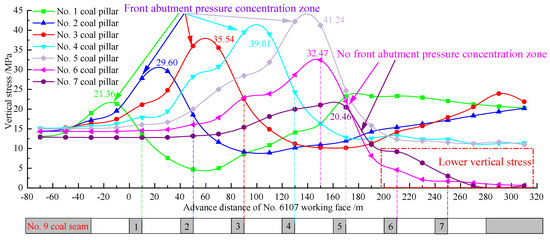
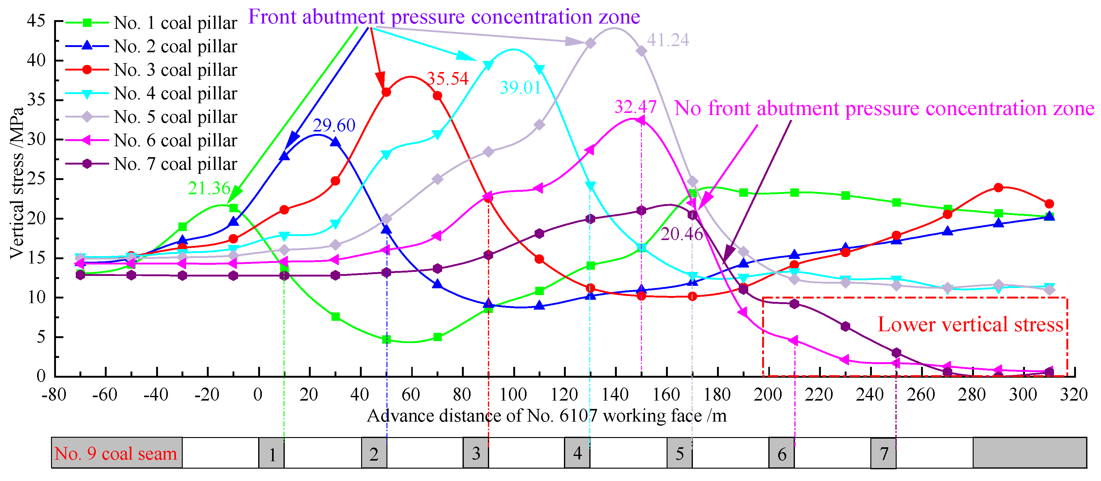
Figure 9.
Vertical stress distribution and evolution law of bottom coal pillar during the mining process of the No.6107 working face.
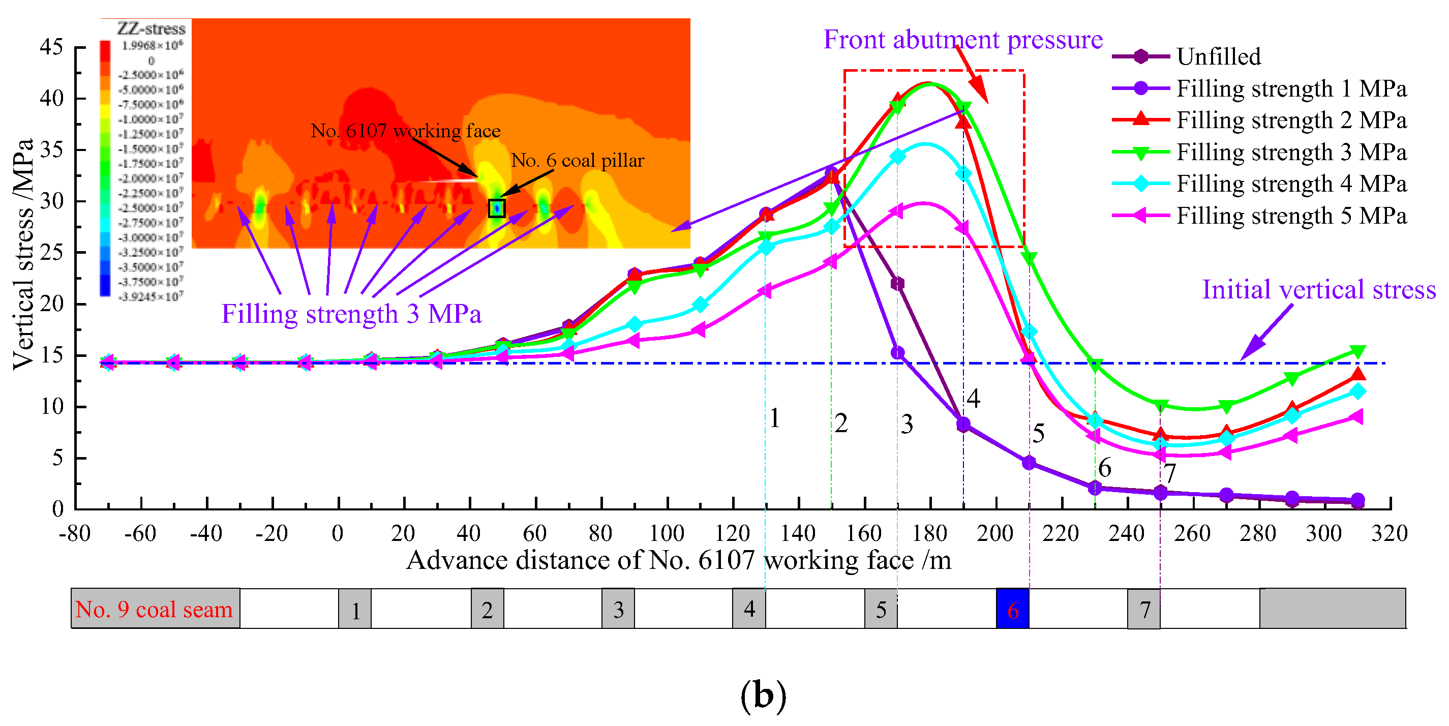
Figure 9 shows that when the No. 6107 working face advanced to the position in front of coal pillars No. 1 to 5, the vertical stresses of the corresponding coal pillars all increased substantially under the effect of the front abutment pressure. These increased from initial vertical stresses of 13.07, 14.43, 15.00, 15.16, and 14.95 MPa to 21.36, 29.60, 35.54, 39.01, and 41.24 MPa, respectively. This indicates that coal pillars No. 1–5 did not fail or destabilize during the process from the cutting eye to pushing out the No. 5 coal pillar in the No. 6107 working face. In addition, with the advancement of the working face, the coal pillar located on the later side suffered from a larger front abutment pressure, and it was more likely to fail and destabilize. Simultaneously, when the working face pushed through the above-mentioned coal pillars, the vertical stresses in their middle interfaces decreased and were lower than their initial vertical stresses. However, as the working face continued to push forward, the vertical stresses in the middle parts of pillars No. 1, 2, and 3 increased and were greater than the initial vertical stresses, whereas the vertical stresses in the middle parts of pillars No. 4 and 5 did not increase. This shows that coal pillars No. 1, 2, and 3 retained a certain bearing capacity and they had not failed in relation to the mining of the No. 6107 working face. However, when the working face was pushed to the front of the No. 5 coal pillar and then through the No. 5 coal pillar, the vertical stresses in the middle of pillars No. 6 and 7 reached their peaks and then decreased as the working face continued to push forward. The vertical stress did not rise in the internal part of the two pillars when the working face was pushed to the position in front of pillars No. 6 and 7, respectively, and it then decreased close to 0MPa, which indicates that these two pillars failed under the front abutment pressure of the No. 6107 working face and had lost their overall bearing capacity.
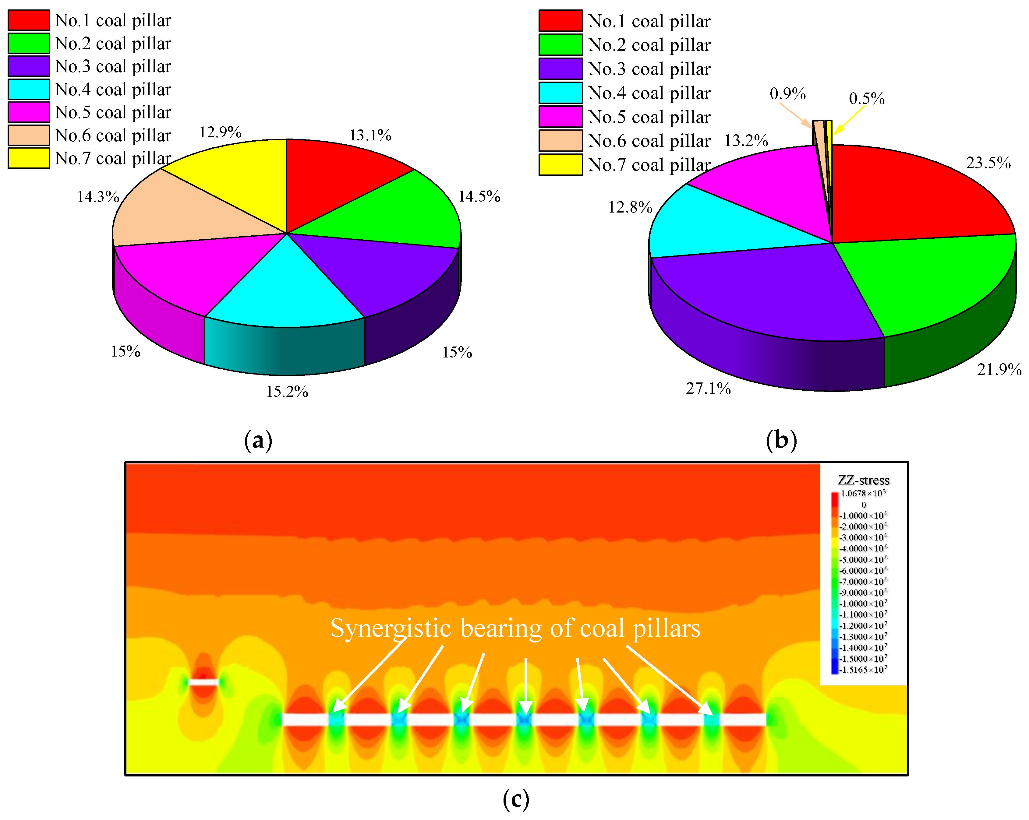
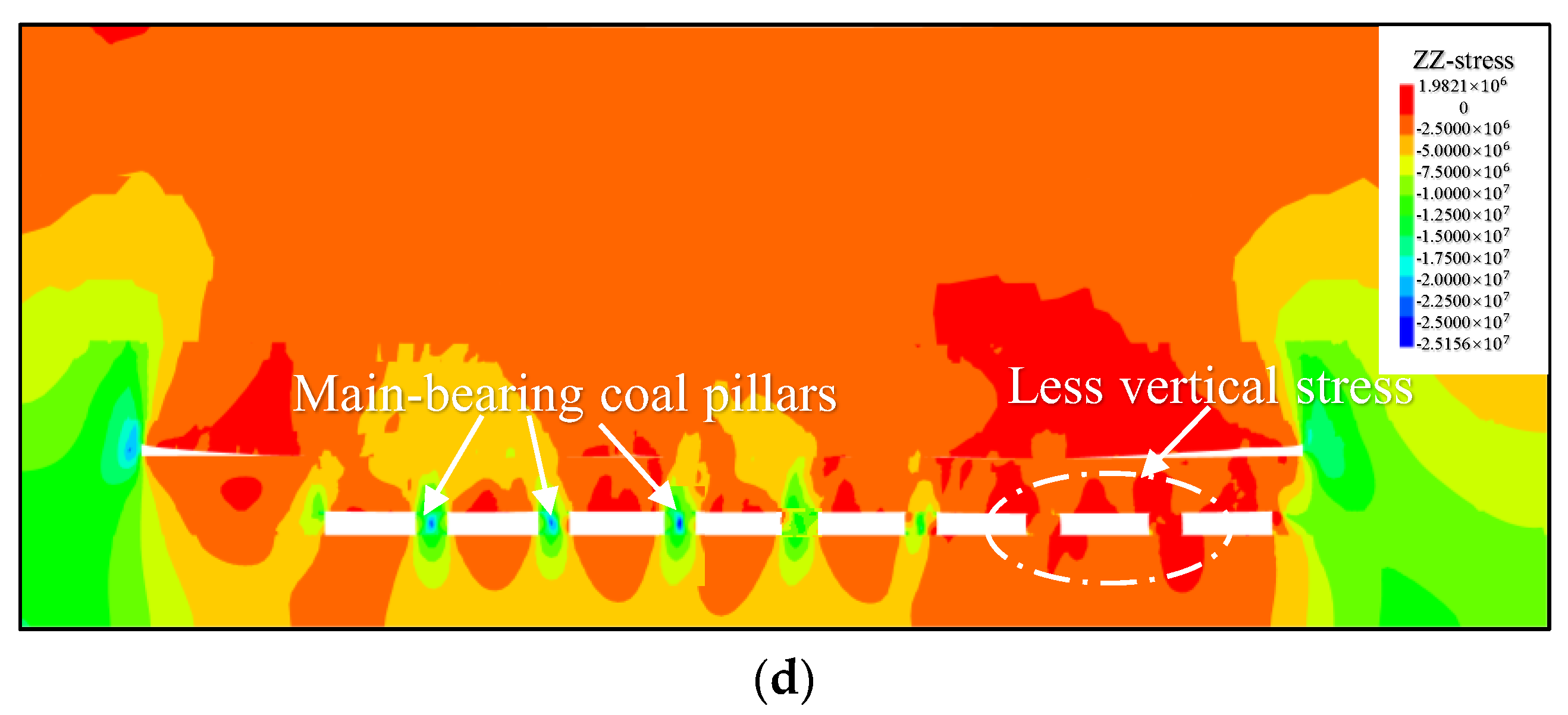
Figure 9 also shows that when the working face advanced to the vicinity of the No. 5 coal pillar, the vertical stresses of the adjacent coal pillars 4 and 5 also continued to decrease and were lower than their initial vertical stresses, respectively, due to the failure and destabilization of pillars 6 and 7. This led to a loss of their load-bearing capacity and a decrease in their vertical stresses, but the vertical stresses of the two pillars remained stable after the advancement of the entire working face. In addition, the vertical stresses of coal pillars No. 1, 2, and 3 increased as the working face continued to advance, indicating that during the advancement of the No. 6107 working face, the destabilization of pillars No. 6 and 7 resulted in the transference of loads of the interlayer strata and overburden of pillars No. 4 and 5, although pillars No. 4 and 5 did not destabilize under the effect of the front abutment pressure. This induced the cascading failure of pillars No. 4 and 5, but they were not completely destabilized and did not lose their load-bearing capacity; the effect did not extend further to cause a destabilization chain in pillars No. 1–3. At this point, the No. 9 seam room-and-pillar mining goaf was transformed from one in which the bearing of the coal pillars at the early stage of mining was coordinated (Figure 10a,c) to one in which the main bearing of pillars No. 1–3 and the synergistic bearing states of Ns. 4–5 operated when the No. 6107 working face was pushed out of the room-and-pillar mining goaf below, as shown in Figure 10b,d.
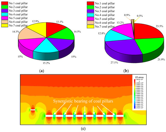
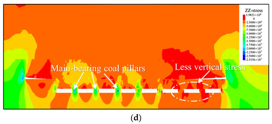
Figure 10.
Comparison of the bearing characteristics of each coal pillar at the initial stage of mining in the No.6107 working face and at the time of pushing out the room-and-pillar mining goaf. (a) Vertical stress percentage of each coal pillar at the initial stage of mining. (b) Vertical stress percentage in each coal pillar at the time of pushing out the room-and-pillar mining goaf. (c) Vertical stress distribution at the beginning of mining. (d) Vertical stress distribution at the time of pushing out the room-and-pillar mining goaf.
4.2. Study of Coal Pillar Stability Based on the Correlation between Stress and Energy
Based on the criterion of “vertical stress lower than initial stress + energy dissipation core connected” for a quantitative study of the characteristics of coal pillars from damage development to macroscopic destructive destabilization, the Fish program was developed in this study to characterize the energy dissipation of the coal and rock mass which was embedded in a numerical simulation computational model of FLAC3D. The dissipated energy distribution characteristics and the dynamic evolution law of the seven bottom coal pillars under mining stress disturbance during the process of mining the No. 6107 working face were investigated. The results were used to capture the gradual expansion of the location of the largest main strain in the plastic damage area of the bottom coal pillars and its dynamic development process, with the aim of revealing the main damage failure point of the bottom coal pillars. Based on the previous analysis, pillars No. 6, 7, 4, 5, and 3 were used as examples (as shown in Figure 11, Figure 12, Figure 13, Figure 14 and Figure 15, respectively) to illustrate the correlation characteristics between the dynamic evolution of vertical stress and the connectivity development law of the dissipative energy core in the advancing process of the No. 6107 working face, with the aim of studying the failure characteristics of the coal pillars under the effect of mining stress perturbation.


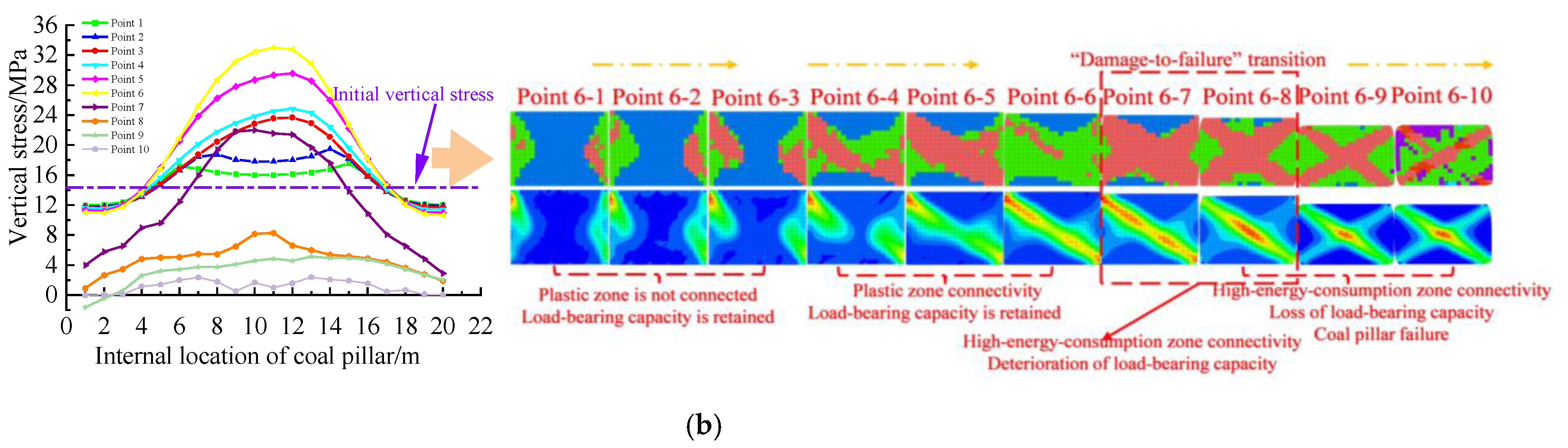
Figure 11.
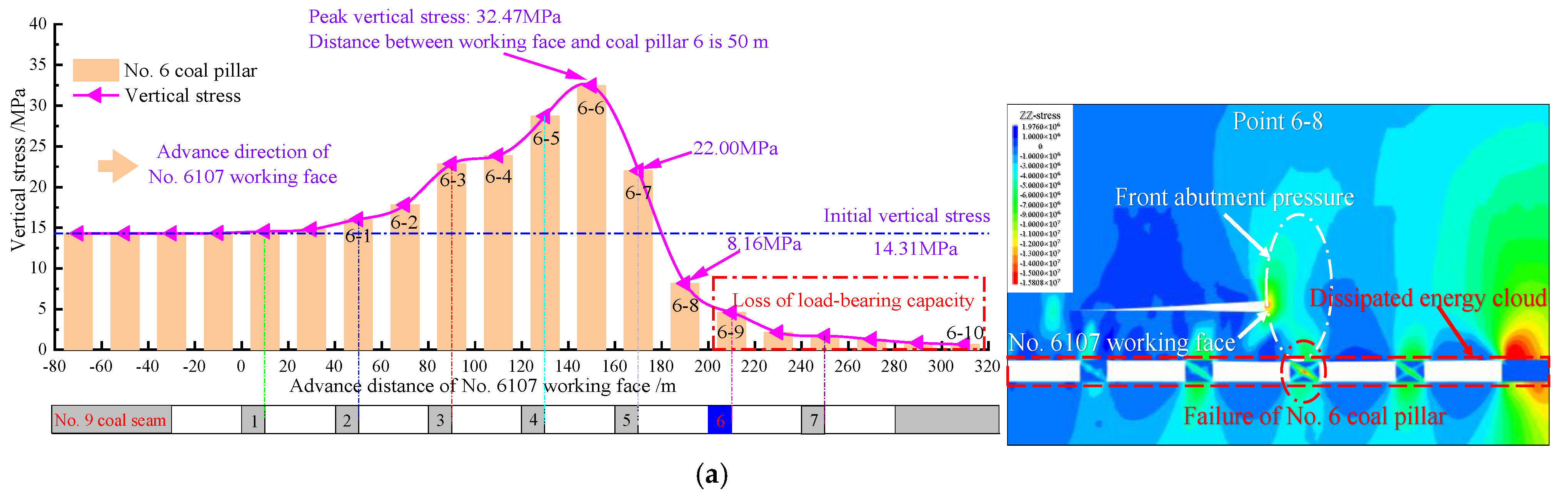
Characteristics of the correlation between vertical stress and energy dissipation in No. 6 coal pillar. (a) Vertical stress evolution law of No. 6 coal pillar. (b) Synergistic evolution law of vertical stress distribution and dissipated energy in the middle of No. 6 coal pillar.

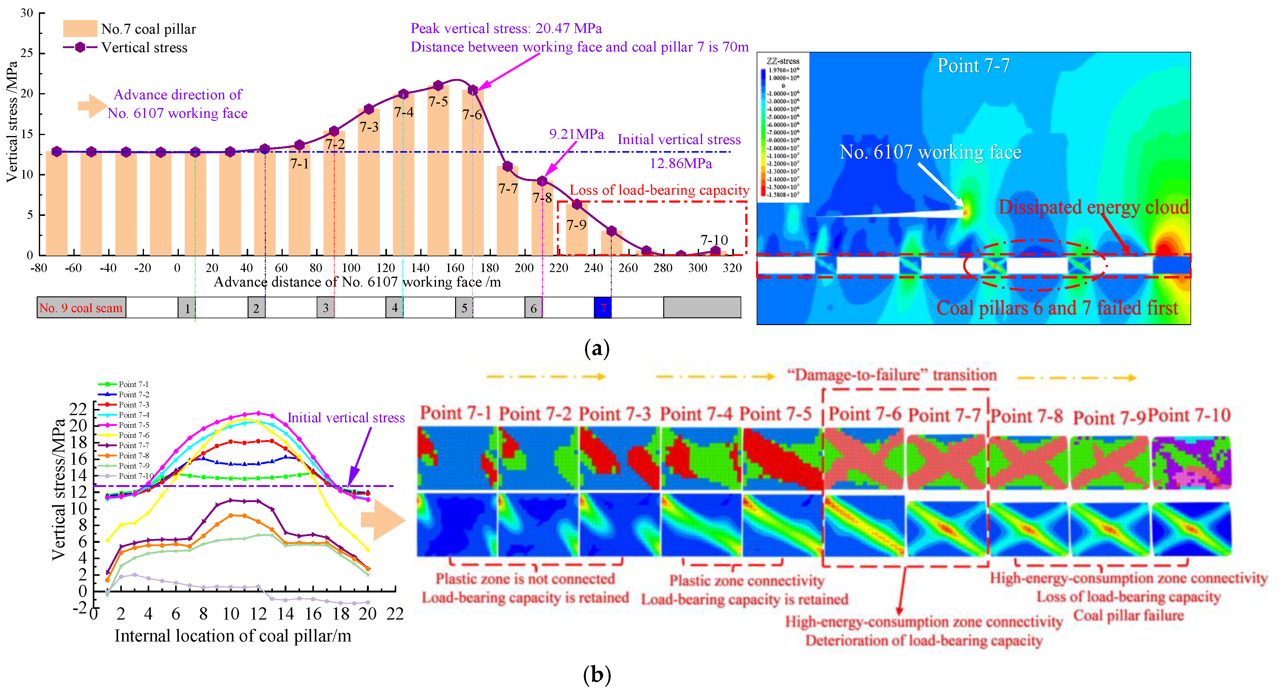
Figure 12.
Characteristics of the correlation between vertical stress and energy dissipation in No. 7 coal pillar. (a) Vertical stress evolution law of No. 7 coal pillar. (b) Synergistic evolution law of vertical stress distribution and dissipated energy in the middle of No. 7 coal pillar.
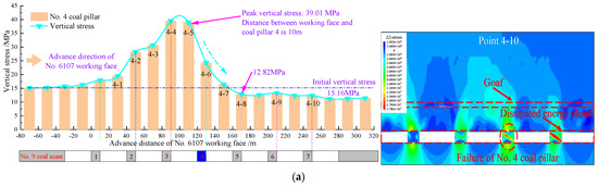
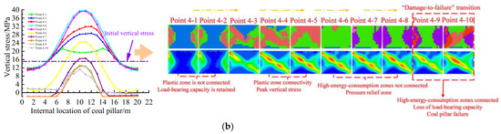
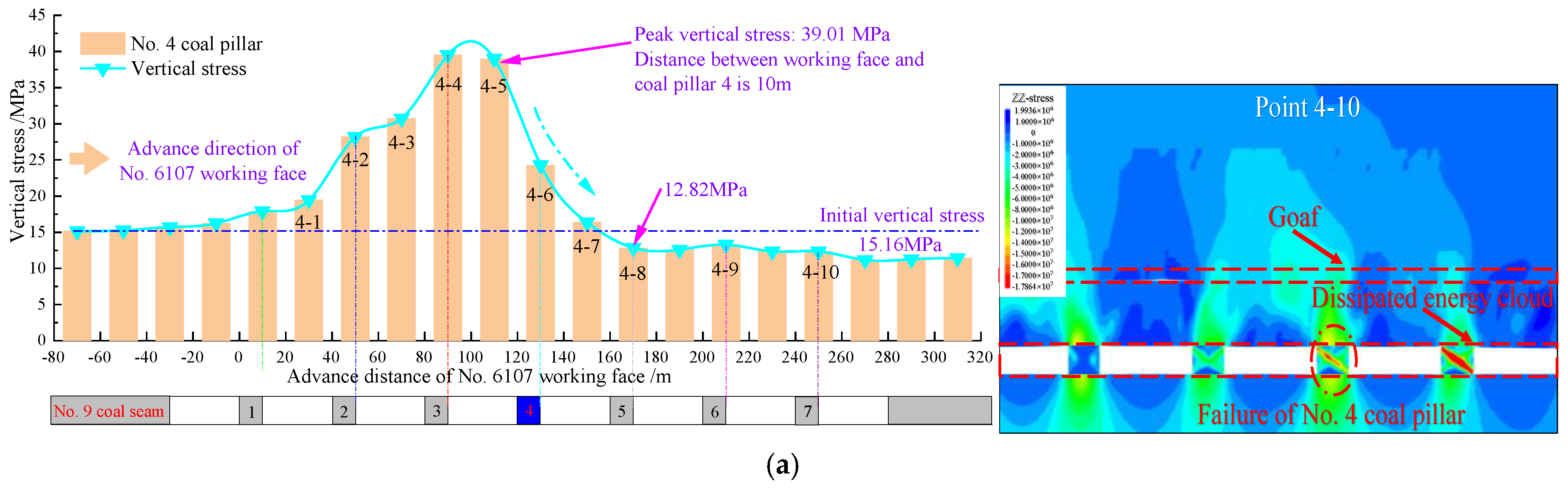
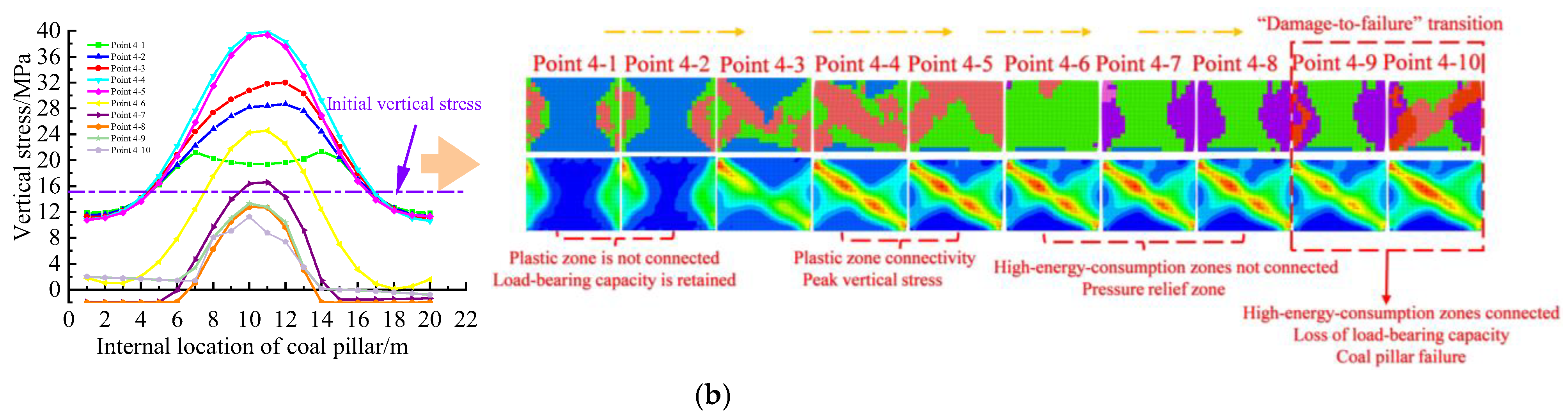
Figure 13.
Characteristics of the correlation between vertical stress and energy dissipation in No. 4 coal pillar. (a) Vertical stress evolution law of No. 4 coal pillar. (b) Synergistic evolution law of vertical stress distribution and dissipated energy in the middle of No. 4 coal pillar.
Figure 14.
Characteristics of the correlation between vertical stress and energy dissipation in No. 5 coal pillar. (a) Vertical stress evolution law of No. 5 coal pillar. (b) Synergistic evolution law of vertical stress distribution and dissipated energy in the middle of No. 5 coal pillar.
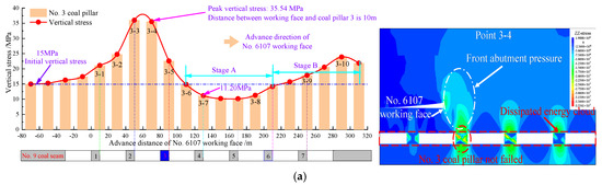

Figure 15.
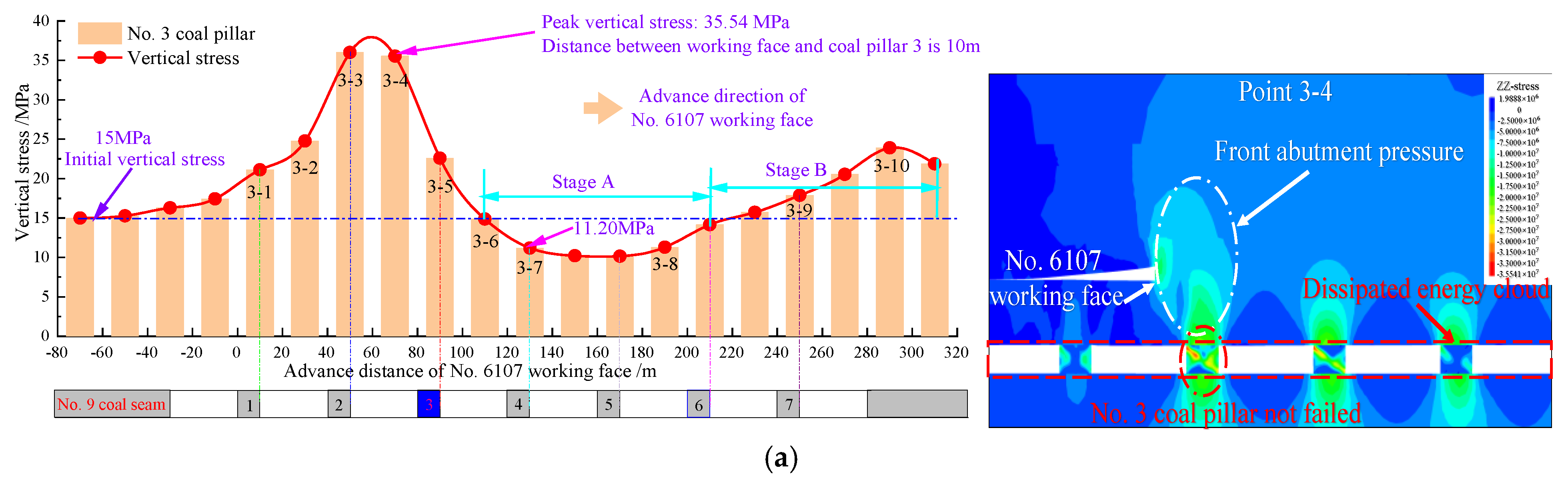
Characteristics of the correlation between vertical stress and energy dissipation in No. 3 coal pillar. (a) Vertical stress evolution law of No. 3 coal pillar. (b) Synergistic evolution law of vertical stress distribution and dissipated energy in the middle of No. 3 coal pillar.
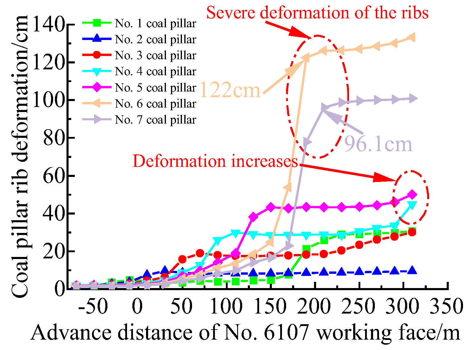
Figure 11 and Figure 12 show that during the disturbance of mining stress in the No. 6107 working face, the vertical stresses in the middle of coal pillars No. 6 and 7 gradually increased compared to the initial rock stress (Figure 11a and Figure 12a). At this point, the main area where the dissipative energy was concentrated in the corresponding coal pillars occurred in the upper left and lower right corners of the pillars. This shows that coal pillar plastic deformation and damage were occurring in these areas, and the main area in which the dissipative energy was concentrated continued to expand from the upper left and lower right corners to the center of the coal pillars until it gradually connected the outer edges of the dissipative area with the advancing of the working face. This shows that large plasticity and rupture occurred along the coal pillar in this direction, but the areas in which the main rupture released energy were not yet connected. When the working face advanced to positions 6-4 and 7-4, respectively, the plastic zones inside the coal pillars were connected (Figure 11b and Figure 12b), but the area in which the dissipative energy was concentrated inside the coal pillars was not connected, and the vertical stress inside the pillars continued to increase with the continued advancement of the working face; this indicates that the coal pillars retained a good load-bearing capacity (Figure 11b and Figure 12b). When the working face advanced to 6-6 and 7-6, respectively, the vertical stresses in the middle of pillars No. 6 and 7 reached a maximum of 32.47 MPa and 20.47 Mpa, respectively. At this time, the working face was 50 m and 70 m away from the corresponding coal pillars, respectively, the outer edges of the dissipative energy core were further connected, and the dissipative energy cores in the upper left and lower right angles were in a state of critical connectivity, which indicates that the main rupture release energy zone along that direction was in a state of critical connectivity. As the face advanced to 6-8 and 7-7, respectively, the vertical stress in the middle of the coal pillars was lower than the initial vertical stress. In addition, the dissipative energy core in the upper left and lower right corners of the coal pillar was completely connected, which indicates that the two coal pillars had formed a completely connected main rupture from the upper left to the lower right (the macroscopic fracture surface of coal pillar sliding damage), and the two pillars were undergoing damage and failure. At this time, the corresponding pillars No. 6 and 7 showed the largest rib deformation of 122 cm and 96 cm, respectively, and as shown in Figure 16, deformation of the coal pillar was seriously destabilized.
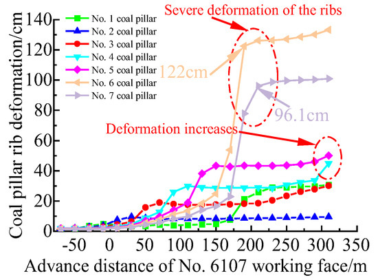
Figure 16.
Deformation pattern of bottom coal pillar ribs during mining of No.6107 working face.
Figure 13 and Figure 14 show that the vertical stresses of pillars No. 4 and 5 began to rise during the advancement of the No. 6107 working face, and they reached a maximum under the effect of the front abutment pressure. As the working face continued to advance, the vertical stresses in the middle of the two coal pillars were gradually reduced to lower than the initial vertical stresses. At the above stage, the dissipative energy cores inside the two coal pillars appeared at the upper left and lower right corners, and they then expanded to the center of the pillars. When the working face pushed through the corresponding coal pillars, and the vertical stress was lower than the initial vertical stress, the dissipative energy cores inside the two pillars were not connected. This further proves that the reduction in vertical stress in the middle of the two pillars at this time was due to the unloading of pressure from mining in the working face. As the face advanced to the positions of 4–10 (40 m to the right of coal pillar No. 7) and 5–8 (pushes through coal pillar No. 7), respectively, the dissipative energy core inside the two coal pillars was connected, and a macroscopic fracture surface of the coal pillar slipping damage was formed. At this time, the two pillars suffered damage and failure. This indicates that pillars No. 4 and 5 were not destabilized under the front abutment pressure, and the destruction and destabilization of these pillars can instead be attributed to the transfer of the overburden loads to them following the destabilization of adjacent pillars No. 6 and 7, which resulted in the sequential destabilization of the pillars No. 4 and 5. Figure 16 shows that the degree of deformation of pillars 4 and 5 was less than that of pillars 6 and 7, and there was a simultaneous and sudden increase in the final curves of rib deformation of the two coal pillars. This further suggests that the two pillars were eventually destabilized.
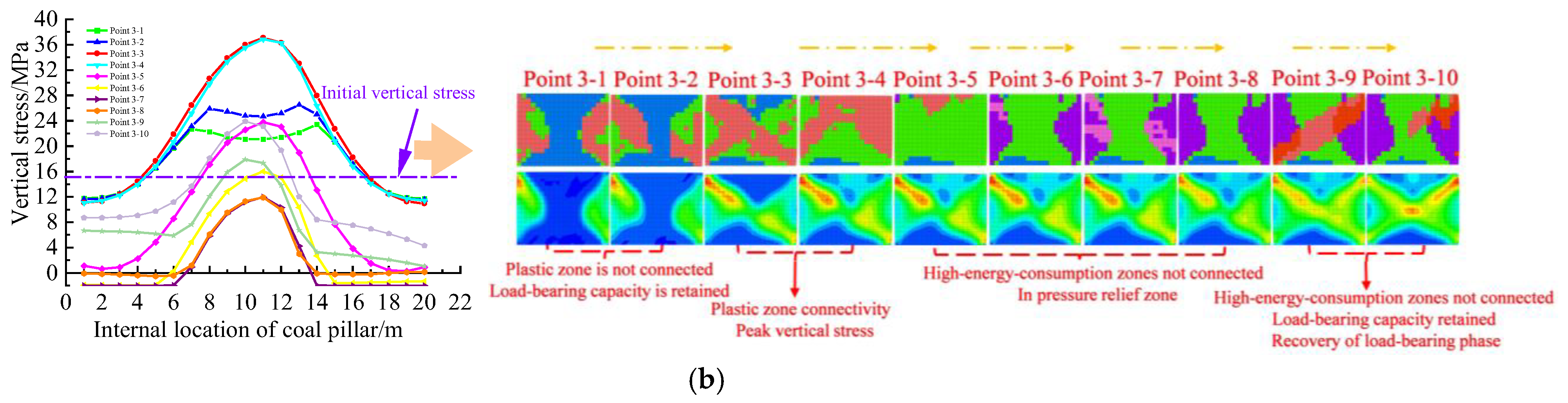
From Figure 15a,b, it is evident that during the process of the advancing No. 6107 working face, the plastic zone of pillar No. 3 under the effect of the front abutment pressure appeared to be connected, and its middle vertical stress distribution was transformed from a saddle shape to a single peak shape. However, during the entire mining process, the dissipative energy core in the coal pillar was not connected, and overall destabilization did not occur. The decrease in vertical stress corresponding to the No. 3 coal pillar (stage A) occurred after the face pushed through the coal pillar, and the main area of concentrated dissipative energy inside the corresponding coal pillar was not connected at this time, indicating that the vertical stress decrease in stage A was due to the pressure relief associated with working face mining. Later, in stage B, the increase in vertical stress was due to the gradual subsidence of the roof strata; as the working face continued to advance, the load continued to be transmitted downward, and subsequent redistribution of the load from the failure of other coal pillars occurred.
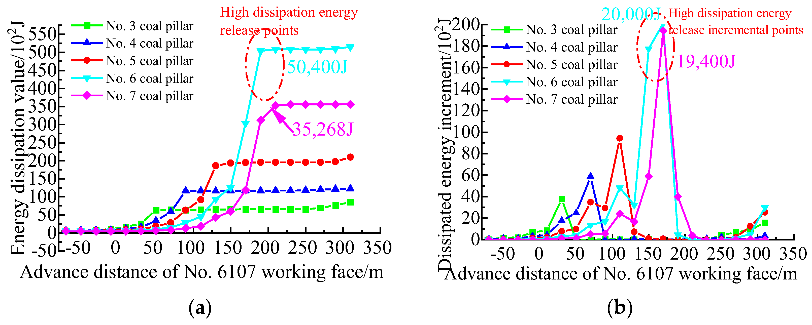
The above results show that there was a good correspondence between “vertical stress drop + connectivity of dissipative energy core” and demonstrate the overall destabilization and loss of bearing capacity of the coal pillars. This enabled the accurate study of the gradual destabilization characteristics of the local damage, crack extension, the main crack penetration, and the overall failure of the coal pillars, as well as allowing the stability of the coal pillars to be reasonably evaluated. In addition, Figure 17 shows that under the effect of mining disturbance in the No. 6107 working face, the cumulative dissipation energy of pillars 6 and 7 was the largest. The dissipation energy curve of the adjacent advancing distance shows a significant sudden increase phenomenon, which indicates that these two coal pillars suffered the most serious destabilization associated with overall failure, whereas the cumulative dissipation energy of pillars No. 4 and 5 was small, and the sudden increase phenomenon was not obvious. Combined with the previous analysis, these results indicate that although pillars No. 4 and 5 showed failure damage, the degree of damage was less than that of pillars 6 and 7, and they retained a certain residual strength.
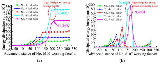
Figure 17.
Working face mining process of No. 6107: (a) evolution of cumulative dissipated energy of coal pillars; (b) incremental evolution of dissipated energy of coal pillars.
5. Discussion
5.1. Effective Measures for Preventing Coal Pillar Failure: Filling
Precisely distinguishing coal pillar failure is the basis of taking reasonable measures to prevent failure. Based on the double indexes of “vertical stress lower than initial vertical stress + energy dissipation core connection” proposed in this paper, this discussion is of great significance for precisely distinguishing coal pillar failure and the selection of reasonable preventive and control measures.
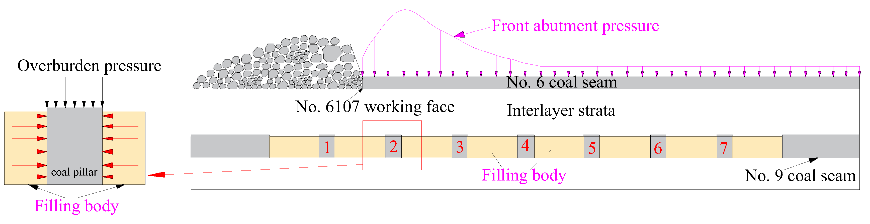
The results showed that the front abutment pressure formed by mining the No. 6107 working face will result in the failure and destruction of bottom coal pillars. This will further result in a loss of bearing capacity, which will seriously threaten the safe mining of the overlying working face. Therefore, we proposed an engineering method that involves grouting and filling the room-and-pillar mining goaf of the No. 9 coal seam to prevent the failure of the bottom coal pillars. As shown in Figure 18, the filling body was formed after solidification of the slurry filling in the room-and-pillar mining goaf; it had a lateral clamping effect on the bottom coal pillar that effectively restrained the expansion of cracks inside the coal pillars and increased the load-bearing capacity of the coal pillars. However, the lateral clamping force on the coal pillars from filling bodies with different strengths varies and affects the stability of the pillars; therefore, determining a reasonable filling strength is crucial for suppressing coal pillar failure and for guiding the proportions of the filling materials required.

Figure 18.
Filling body clamping action strengthens the load-bearing capacity of coal fillers to prevent failure.
5.2. Reasonable Filling Body Strength
To determine a reasonable strength of the slurry filling employed to backfill the room-and-pillar mining goaf in the No. 9 coal seam and prevent coal pillar failure, a numerical simulation was conducted. Improvements in the stability of the bottom coal pillars were analyzed by employing differing filling body strengths of 1, 2, 3, 4, and 5 MPa.
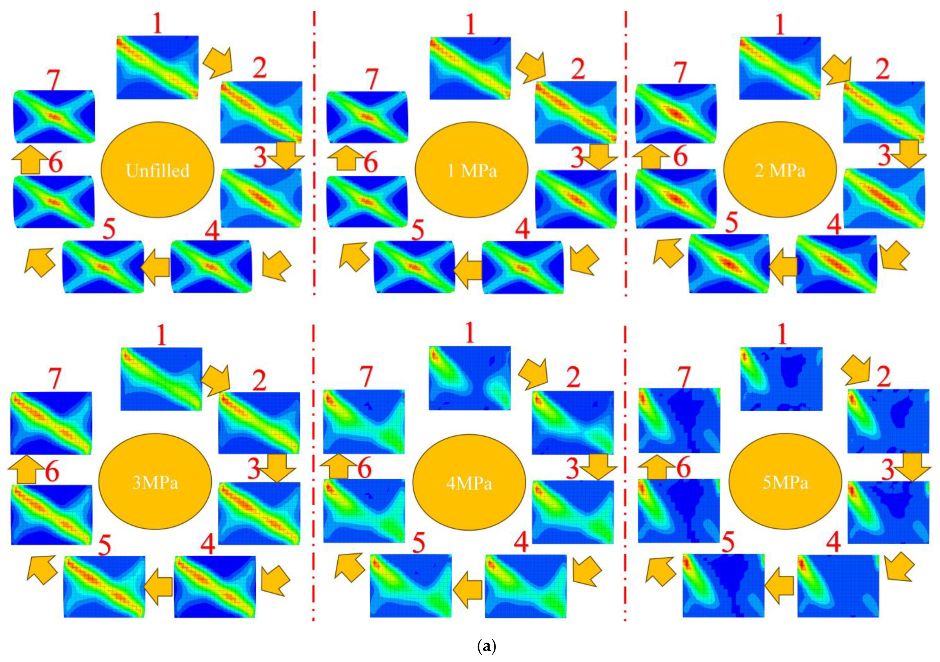
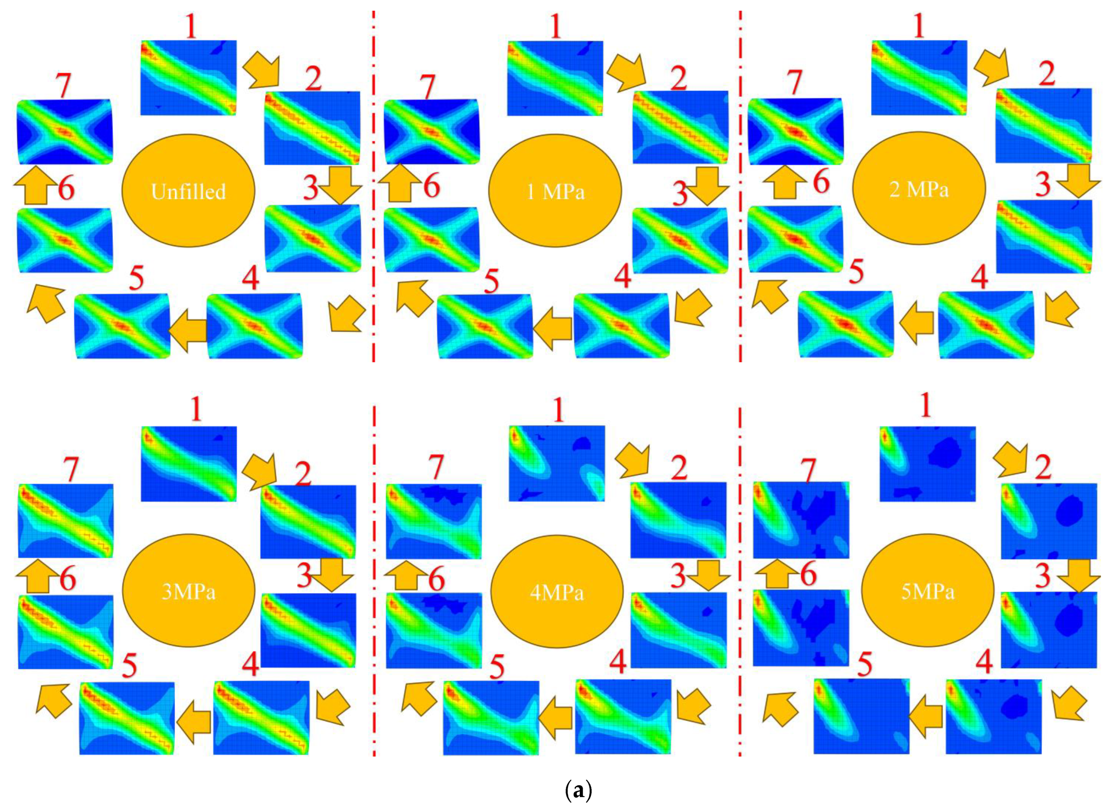
In this study, we utilised coal pillars No. 6, 7, 4, and 5 as examples to demonstrate the impact of filling bodies with different strengths on the bearing capacity of bottom coal pillars. The corresponding vertical stress evolution laws and connection characteristics of the main areas in which dissipative energy was concentrated were obtained, and the results are shown in Figure 19, Figure 20, Figure 21 and Figure 22, respectively.


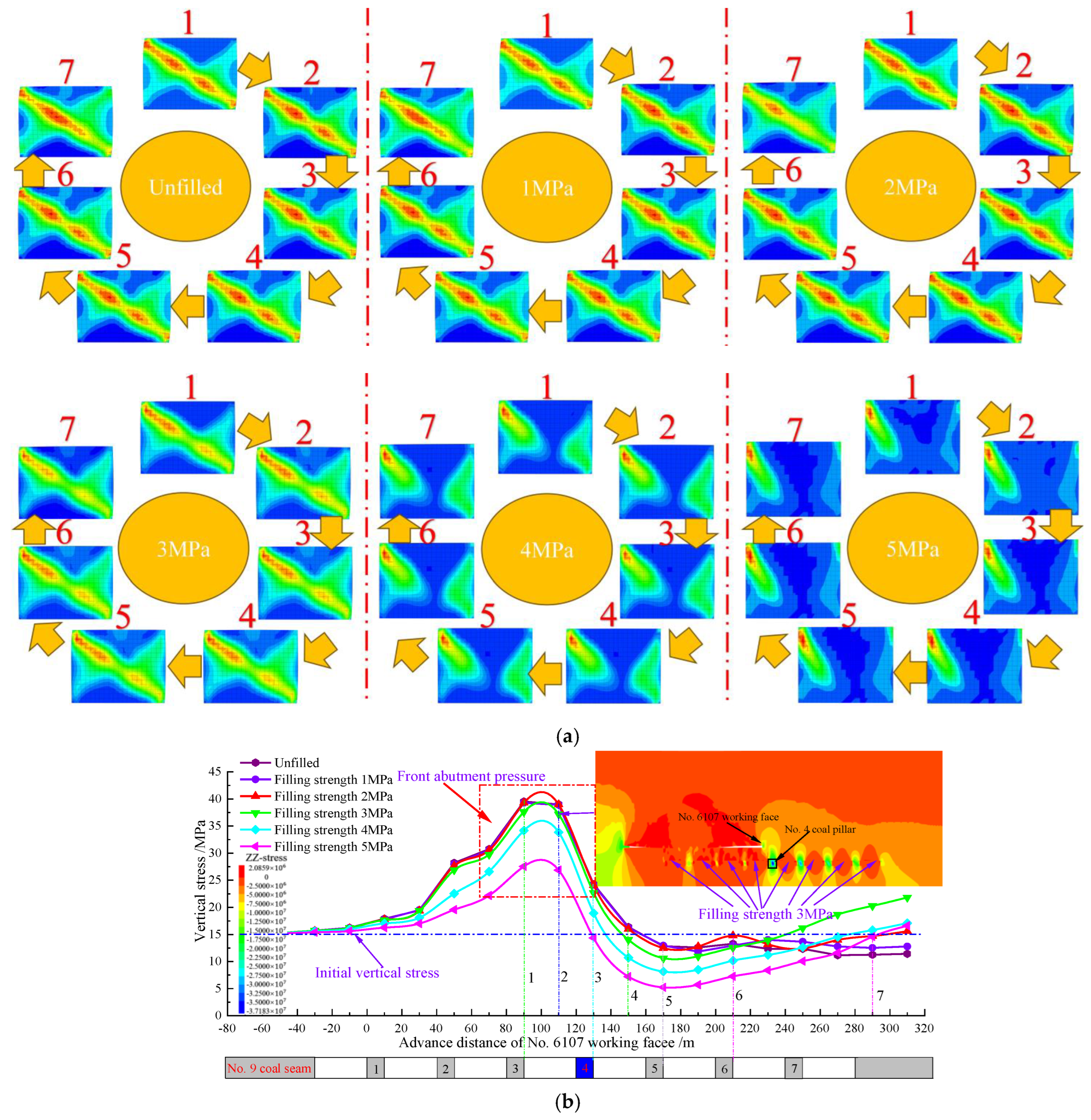
Figure 19.
Clamping effect of using filling bodies with different strengths in coal pillar No. 6: (a) characteristics of dissipation energy development and its core connectivity law; (b) vertical stress evolution law.

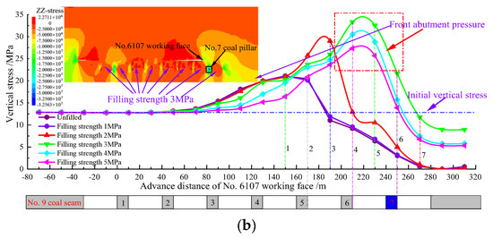
Figure 20.
Clamping effect of using filling bodies with different strengths in coal pillar No. 7: (a) characteristics of dissipation energy development and its core connectivity law; (b) vertical stress evolution law.
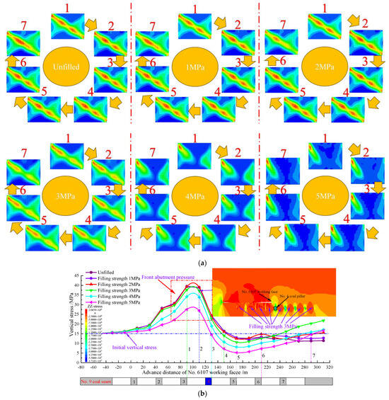
Figure 21.
Clamping effect of using filling bodies with different strengths in coal pillar No. 4: (a) characteristics of dissipation energy development and its core connectivity law; (b) vertical stress evolution law.
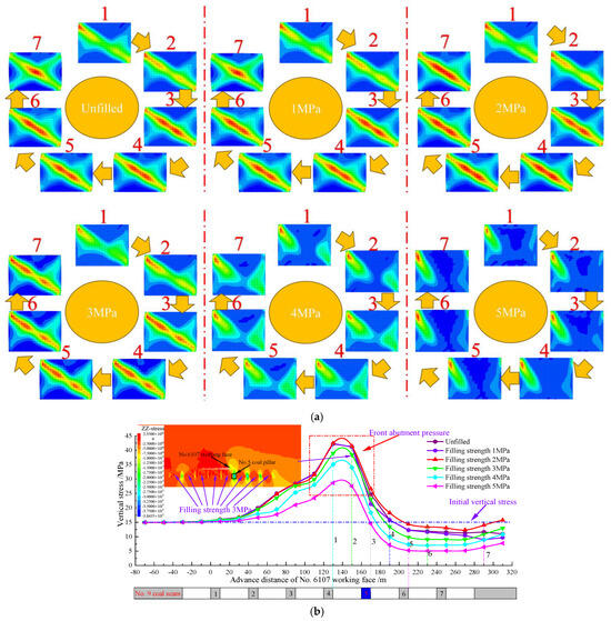
Figure 22.
Clamping effect of using filling bodies with different strengths in coal pillar No. 5: (a) characteristics of dissipation energy development and its core connectivity law; (b) vertical stress evolution law.
As shown in Figure 19 and Figure 20, when the strength of the filling body was 1 MPa and unfilled, the upper left and lower right corners of pillars 6 and 7 were gradually connected to the dissipative energy core developed in the center of the coal pillar under the effect of the front abutment pressure in the No. 6107 working face (Figure 19a and Figure 20a). Both pillars formed a monoclinal penetration-type failure section, leading to the overall collapse and destabilization, and their middle vertical stress distributions and evolutionary patterns were similar throughout the entire mining process (Figure 19b and Figure 20b). This indicates that the lateral clamping forces formed by the filling body with a strength of 1 MPa were insufficient to prevent the failure of the coal pillars. When the strength of the filling body was 2 MPa, the bearing capacity of pillars 6 and 7 was increased under the clamping action of the filling body, and front abutment pressure was formed in the middle of pillar No. 6 when the working face advanced to its front. However, the front abutment pressure decreased and was lower than the initial vertical stress when it pushed through the coal pillar, as shown in Figure 19b. Furthermore, the main area in which dissipative energy was concentrated in pillar No. 6 was connected under the high front abutment pressure, and the coal pillar underwent destructive failure, as shown in Figure 19a. While the advancing position of the upper working face at the time of peak stress formation within the No. 7 coal pillar corresponded to a 20m advance compared to the unfilled position, a reduction in vertical stress still occurred at the position in front of No. 7 coal pillar, and the main areas in which dissipative energy was concentrated inside the coal pillar were connected.
With a filling body strength of 3 MPa, the bearing capacities of pillars No. 6 and 7 were greatly increased under the clamping action of the filling body, and the two coal pillars formed the front abutment pressure. Vertical stress drops occurred in the No. 6107 working face after it pushed through the corresponding coal pillars; however, the dissipative energy core of the two coal pillars was not completely connected but was in the state of critical connectivity. When the filling body strength increased to 4 MPa and 5 MPa, the vertical stresses decreased in pillars 6 and 7, and the dissipative energy core of these pillars did not appear to be connected from the beginning to the end, and there was only a relatively small intersection in the boundary area of the outer edge of dissipative energy. Furthermore, the vertical stresses of both coal pillars showed characteristics of first increasing and then decreasing, and it is evident that the increased filling body strength greatly enhanced the stability of the bottom coal pillars under the stress perturbation of re-mining. These results show that the strength of the filling body should be greater than or equal to 3 MPa.
As shown in Figure 21 and Figure 22, with filling body strengths of 1 MPa and 2 MPa, the vertical stress distributions and their evolutionary patterns in the middle of pillars No. 4 and 5 under the stress perturbation of re-mining were close to those of the unfilled ones, and the final vertical stresses were all smaller than the initial vertical stresses (Figure 21b and Figure 22b). Meanwhile, the dissipative energy core inside the corresponding coal pillars gradually developed and connected from the upper left and lower right corners toward the center of the coal pillars, as shown in Figure 21a and Figure 22a. This shows that the lateral clamping force provided by the filling body with strengths of 1 MPa and 2 Mpa was insufficient to prevent failure caused by load redistribution on pillars 6 and 7 due to failure damage. With a filling body strength of 3 Mpa, the bearing capacities of pillars 4 and 5 were greatly increased under the clamping action of the filling body, and their final vertical stresses all rose. In addition, the dissipative energy core of the two pillars was not completely connected and was in a state of critical connectivity. With an increase in the filling body strength to 4 Mpa and 5 Mpa, the vertical stresses of pillars 4 and 5 decreased, indicating that under the clamping effect of the high-strength filling body, pillars No. 6 and 7 were stabilized and their load-bearing capacities were greatly increased; this shared and reduced the overburden loads of pillars No. 4 and 5. Therefore, when the strength of the filling body was greater than or equal to 3 Mpa, the stability of coal pillars in the No. 9 coal seam could be greatly enhanced, thus ensuring the safe mining of the No. 6107 working face.
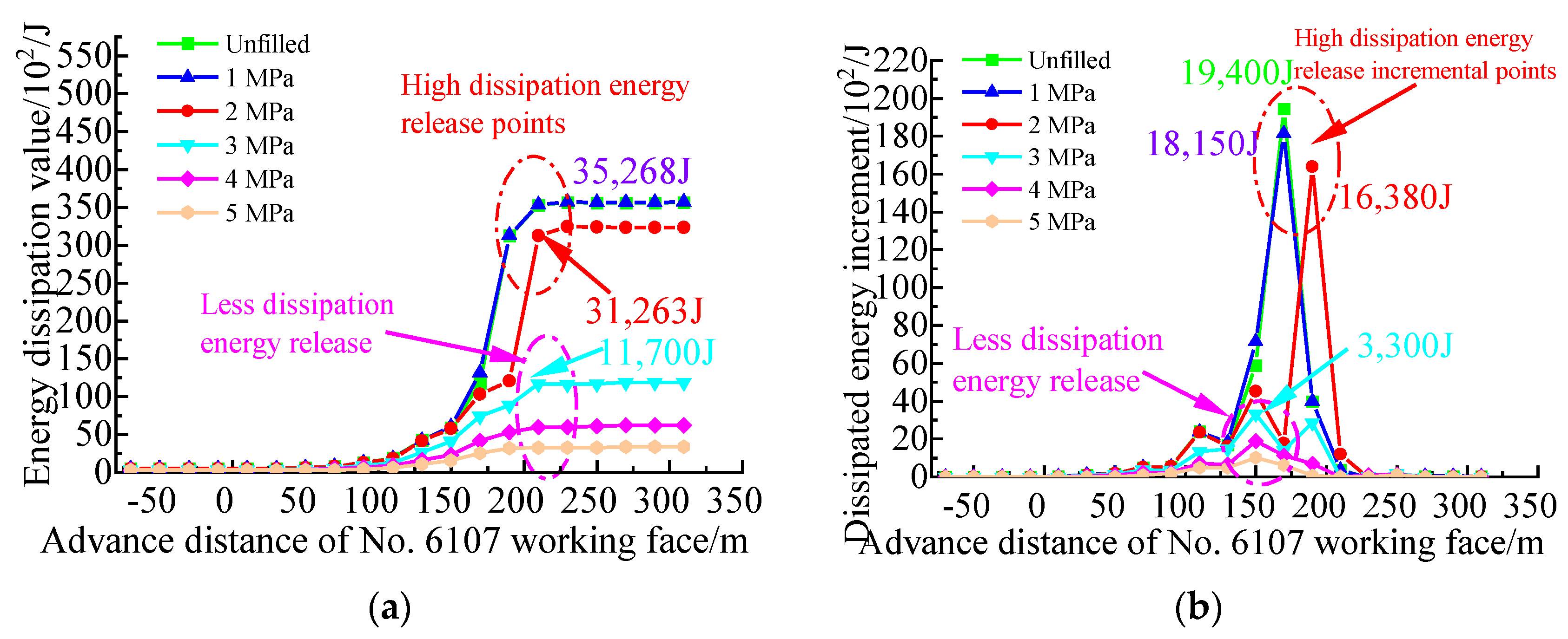
To further analyze the influence of using different filler strengths on the stability of the bottom coal pillars under the effect of mining stress perturbation, the cumulative dissipation energy evolution characteristics of pillars No. 6 and 7 were obtained and are shown in Figure 23 and Figure 24. These pillars were the first to be destabilized in the previous analysis, and they showed a larger degree of destruction than the other pillars. The figures show that under the effect of mining disturbance in the No. 6107 working face, the cumulative dissipation energy of pillars No. 6 and 7 was the largest with a filling body strength of 1 Mpa, and the difference between the cumulative dissipation energy of the corresponding unfilled coal pillars was small. Simultaneously, the dissipation energy curves of their adjacent advancing distances all showed substantial sudden increase phenomena, which further suggests that the clamping provided by a filling body with a strength of 1 Mpa was insufficient to prevent the failure of coal pillars. When the filling body strength was increased to 2 Mpa, the cumulative dissipation energy of the corresponding coal pillars decreased, although the decrease was small, and the cumulative dissipation energy of pillars No. 6 and 7 decreased from 50,400 J and 35,268 J to 31,902 J and 31,263 J (decreases of 36.7% and 11.35%), respectively. Nevertheless, the sudden increase in their cumulative dissipation energy was still notable. Combined with the results obtained above, it was evident that the failure of both pillars 6 and 7 occurred with a filling body strength of 2 Mpa, but the degree of damage was reduced compared to that with a strength of 1 Mpa. However, when the strength of the filling body was increased to 3 Mpa, the cumulative dissipation energy of pillars No. 6 and 7 decreased substantially from 31,902 J and 31,263 J to 14,100 J and 11,700 J, respectively, with decreases of 55.8% and 62.6%; these decreases were comparatively larger than those with a filling body strength of 2 Mpa, and the sudden increase phenomena were unclear. With further increases in the filling body strength, the cumulative dissipation energy of the two coal pillars was small and there was no obvious sudden increase, which indicates that the corresponding coal pillars were subjected to a very small range of damage and they remained stable.
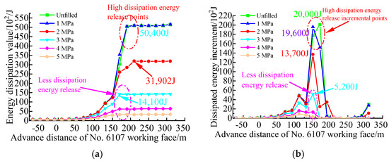
Figure 23.
Clamping effect of using filling bodies with different strengths in coal pillar No. 6: (a) evolution of cumulative dissipated energy; (b) evolution of incremental dissipated energy.
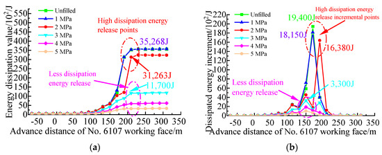
Figure 24.
Clamping effect of using filling bodies with different strengths in coal pillar No. 7: (a) evolution of cumulative dissipated energy; (b) evolution of incremental dissipated energy.
5.3. Field Practice
Grout filling of the room-and-pillar mining goaf can mainly be achieved by drilling and grouting at the ground level of the No. 6107 working face. Considering the long-distance transportation of a ground pipeline and the strength requirements, we proposed the use of a mixed slurry of fly ash and cement. The above results showed that with a filling body strength greater than (or equal to) 3 MPa, the grouting filling body would provide a sufficient lateral clamping force to the coal pillars in the No. 9 coal seam, and this would improve their load-bearing capacity and prevent failure.
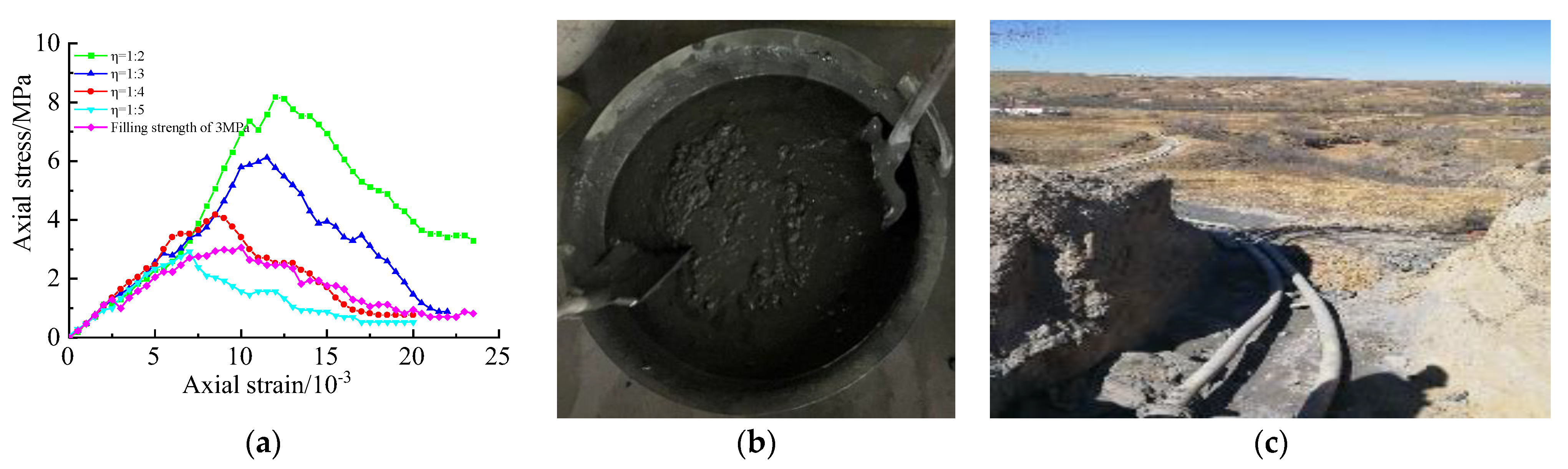
Therefore, it is necessary to analyze the most reasonable proportion of fly ash and cement required to satisfy the filling requirements and to also consider the influence of the time effect of the consolidation action of the grouted filling body on its strength. During field operations, mining in the No. 6107 working face began 28 days after the completion of grouting and filling in the No. 9 seam room-and-pillar mining goaf. This led to inaccurate assessments of the strength of the filling body at the engineering scale, as the consolidation time of filling body specimens with shorter proportions did not reflect their true strength [45]. Different fly ash to cement proportions (mass ratios (η) of 2:1, 3:1, 4:1, and 5:1) at 28 days were selected to determine the optimum laboratory physio-mechanical parameters. The results were then compared (Figure 25a) with those of the filling physio-mechanical parameters obtained via the numerical simulation when a strength of 3 MPa was used, and fly ash to cement mass ratios of 2:1, 3:1, and 4:1 were found to meet the filling strength requirements. To avoid water resolution, the amount of cement incorporated should not be too high; therefore, a filling slurry with a fly ash to cement mass ratio of 4:1 was selected, as shown in Figure 25b. In addition, fly ash with a low calcium oxide content was selected to reduce the degree of hydration reaction and the cementitious compound formation rate. A certain amount of lignosulfonate retardant was also employed to prevent the cement from curing and solidifying. Notably, the grouting process took full advantage of the terrain and adopted unpressurized self-flow conveyance. The filling pipeline is shown in Figure 25c.

Figure 25.
(a) Comparison between strengths of specimens with different fly ash cement proportions (at 28 days) obtained using a numerical simulation; (b) initial filling slurry; (c) filling pipelines.
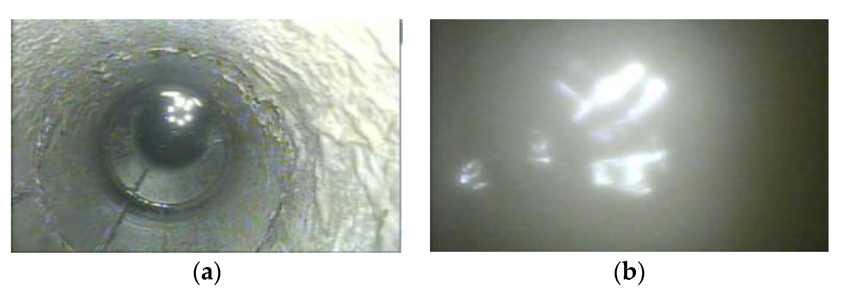
As an unavoidable dry shrinkage effect occurs during the filling slurry consolidation process and the filling body between the bottom coal pillars of the horizontal surplus space increases to a certain extent, there is a slight reduction in the lateral clamping force of the filling body in the bottom coal pillars. The effective filling height of the room-and-pillar mining goaf below the No. 6107 working face also has an important influence on the stability of the coal pillars. Therefore, the room-and-pillar mining goaf of the No. 9 coal seam under the No. 6107 working face was filled up as far as possible, and in situ observations of the filling effect on the room-and-pillar mining goaf and the stability of the coal pillars under the effect of mining were conducted using borehole TV via unsealed grouted boreholes. Combined with the earlier results, these results showed that the No. 6 coal pillar in the middle of the No. 9 coal seam was the first to exhibit destructive failure; therefore, the TV observation hole was located in the middle of the No. 9 coal seam room-and-pillar mining goaf. The drilling TV monitor was first lowered to a depth of 160.505 m to observe this mining area (Figure 26a), and it was then lowered to −162.595 m to observe the water surface of the filling area, as shown in Figure 26b. The No. 9 coal seam room-and-pillar mining goaf in this range has an unconnected roof height of approximately 2 m, and the height of the filling body basically reaches more than 6 m. A good filling effect was achieved, and this means that the No. 6107 working face could be safely pushed through at a later stage.
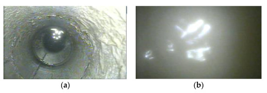
Figure 26.
(a) Water accumulated at the bottom of the drill hole; (b) water accumulated in the filling area.
6. Conclusions
(1) To quantify the damage degree of the load-bearing coal pillar under the stress perturbation of re-mining, a Fish program was developed based on energy evolution calculations of the strain-softened coal and rock mass. A numerical simulation method was proposed to characterize both the gradual damage occurring to the load-bearing coal pillar and the energy evolution law on an engineering scale. A method for evaluating the stability of the pillar was also proposed, where the dual criterion of “the vertical stress is lower than the initial vertical stress + the connectivity of the dissipative energy core” was employed; this was useful for conducting a quantitative analysis of the damage to the coal pillar and its instability.
(2) The gradual instability associated with local damage, crack extension, and the main crack penetration to the overall failure of the bottom coal pillar and the failure propagation characteristics of the coal pillar cluster during the upward mining process of the coal seam were analyzed through a simulation. In the process of overlying the mining working face, the backward coal pillars were seen to be subjected to greater front abutment pressure and were more prone to failure. The vertical stresses in the middle of pillars No. 6 and 7 appeared to decrease with the front abutment pressure during the advancement of the working face. The dissipative energy core in the corresponding coal pillars developed from the upper left and lower right corners to the center of the pillars, and finally formed a monoclinic through-type shear section at the center of the pillars; therefore, pillars No. 6 and 7 would be the first to be damaged and to fail under the effect of the front abutment pressure. Furthermore, the simulation showed that overburden loads would be transmitted to pillars No. 5 and 4, which would induce the failure of these two coal pillars, albeit to a lesser extent than pillars 6 and 7, and pillar No. 5 would reach the first instability zone and ultimate failure before No. 4. However, pillars 1, 2, and 3 would not fail, and they would continue to support the overburden after the working face was pushed through. Therefore, the bearing of the coal pillars changed from the synergistic bearing of each coal pillar to the main bearing of pillars 1 to 3 and the synergistic bearing of pillars 4 and 5 to the overburden.
(3) An engineering method was proposed that employed slurry filling of the room-and-pillar type of the No. 9 coal seam goaf with the aim of preventing coal pillar failure. A reasonable slurry filling body strength was determined, and the results showed the following: the greater the strength of the filling body, the stronger the lateral clamping force formed on the coal pillars; this was conducive to restraining the expansion of the internal cracks of the coal pillars and improving their load-bearing capacity. With filling body strengths of 1 MPa and 2 MPa, pillars No. 6 and 7 were destabilized, which then led to the cascading destabilization of pillars 4 and 5. When the strength of the filling body was increased to 3 MPa, pillars 6 and 7 remained stable. With an increase in the filling body strength, the vertical stresses of pillars No. 6 and 7 first increased and then decreased, while the vertical stresses of pillars 1–5 showed a monotonic decrease. In this respect, when the filling body strength was greater than 3 MPa, the entire coal pillar cluster realized synergistic bearing on the overlying strata of the No. 6107 working face. Therefore, the filling body strength should be greater than 3 MPa.
(4) The combined engineering practice and numerical simulation results showed that the optimum ratio of fly ash to cement was 4:1. Filling slurry and grouting should be prepared to fill the No. 9 coal seam room-and-pillar mining goaf as far as possible to weaken the dry shrinkage effect that occurs during the solidification process of the filling slurry. The drilling TV observations of the filling effect of the goaf showed that the middle part of the room-and-pillar mining goaf of the No. 9 coal seam was more densely filled, and the joint carrier formed by the bottom coal pillars and the filling bodies maintained mining activity stability.
Author Contributions
Z.L., conceptualization, methodology, formal analysis, investigation, data curation, writing—review and editing, and funding acquisition; J.F., methodology, software, investigation, data curation, and writing—original draft; G.F., methodology, writing—review and editing, and funding acquisition; C.Q., investigation; J.Z., investigation. All authors have read and agreed to the published version of the manuscript.
Funding
The authors appreciate the financial support from the Joint Funds of the National Natural Science Foundation of China (Grant No. U22A20169), the National Natural Science Fund for Distinguished Young Scholars, China (Grant No. 51925402), and the Youth Scientific Research Project for Shanxi Provincial Basic Research Program (Grant No. 202203021222325). This work has been supported by the New Cornerstone Science Foundation through the XPLORER PRIZE.
Data Availability Statement
The data involved in this paper are all included in the text of the manuscript.
Conflicts of Interest
The authors declare no conflict of interest.
References
- Madhavi, M.; Nuttall, W.J. Coal in the Twenty-first Century: A Climate of Change and Uncertainty. Proc. Inst. Civ. Eng. Energy 2019, 172, 46–63. [Google Scholar] [CrossRef]
- Cronshaw, I. World Energy Outlook 2014 Projections to 2040: Natural Gas and Coal Trade, and the Role of China. Aust. J. Agric. Resour. Econ. 2015, 59, 571–585. [Google Scholar] [CrossRef]
- Berest, P.; Brouard, B.; Feuga, B.; Karimi-Jafari, M. The 1873 Collapse of the Saint-Maximilien Panel at the Varangeville Salt Mine. Int. J. Rock Mech. Min. Sci. 2008, 45, 1025–1043. [Google Scholar] [CrossRef]
- Cui, X.M.; Gao, Y.G.; Yuan, D.B. Sudden Surface Collapse Disasters Caused by Shallow Partial Mining in Datong Coalfield, China. Nat. Hazards 2014, 74, 911–929. [Google Scholar] [CrossRef]
- Sears, M.M.; Rusnak, J.; Van Dyke, M.; Rashed, G.; Mohamed, K.; Sloan, M. Coal Rib Response During Bench Mining: A case study. Int. J. Min. Sci. Technol. 2018, 28, 107–113. [Google Scholar] [CrossRef] [PubMed]
- Galvin, J.M. Ground Engineering-Principles and Practices for Underground Coal Mining; Springer: Berlin, Germany, 2016. [Google Scholar]
- Xu, J.M.; Zhu, W.B.; Ju, J.F. Mechanism of Dynamic Mine Pressure Occurring Below Adjacent Upper Chamber Mining Goaf with Shallow Cover Depth. J. China Coal Soc. 2017, 42, 500–509. (In Chinese) [Google Scholar]
- Ju, J.F.; Xu, J.L.; Zhu, W.B. Longwall Chock Sudden Closure Incident Below Coal Pillar of Adjacent Upper Mined Coal Seam Under Shallow Cover in the Shendong Coalfield. Int. J. Rock Mech. Min. Sci. 2015, 77, 192–201. [Google Scholar] [CrossRef]
- Jaiswal, A.; Shrivastva, B.K. Numerical Simulation of Coal Pillar Strength. Int. J. Rock Mech. Min. Sci. 2009, 46, 779–788. [Google Scholar] [CrossRef]
- Poulsen, B.A.; Shen, B. Subsidence Risk Assessment of Decommissioned Bord-and-pillar Collieries. Int. J. Rock Mech. Min. Sci. 2013, 60, 312–320. [Google Scholar] [CrossRef]
- Cording, E.J.; Hashash, Y.M.A.; Oh, J. Analysis of Pillar Stability of Mined Gas Storage Caverns in Shale Formations. Eng Geol. 2015, 184, 71–80. [Google Scholar] [CrossRef]
- Singh, R.; Singh, A.K.; Maiti, J.; Mandal, P.K.; Singh, R.; Kumar, R. An Observational Approach for Assessment of Dynamic Loading During Underground Coal Pillar Extraction. Int. J. Rock Mech. Min. Sci. 2011, 48, 794–804. [Google Scholar] [CrossRef]
- Prassetyo, S.H.; Irnawan, M.A.; Simangunsong, G.M.; Wattimena, R.K.; Arif, I.; Rai, M.A. New Coal Pillar Strength Formulae Considering the Effect of Interface Friction. Int. J. Rock Mech. Min. Sci. 2019, 123, 19. [Google Scholar] [CrossRef]
- Poulsen, B.A. Coal Pillar Load Calculation by Pressure Arch Theory and Near Field Extraction Ratio. Int. J. Rock Mech. Min. Sci. 2010, 47, 1158–1165. [Google Scholar] [CrossRef]
- Zhang, C.; Zhao, Y.X.; Han, P.H.; Bai, Q.S. Coal Pillar Failure Analysis and Instability Evaluation Methods: A Short Review and Prospect. Eng. Fail. Anal. 2022, 138, 19. [Google Scholar] [CrossRef]
- Esterhuizen, G.S.; Dolinar, D.R.; Ellenberger, J.L. Pillar Strength in Underground Stone Mines in the United States. Int. J. Rock Mech. Min. Sci. 2011, 48, 42–50. [Google Scholar] [CrossRef]
- Zhou, Z.L.; Chen, L.; Zhao, Y.; Zhao, T.B.; Cai, X.; Du, X.M. Experimental and Numerical Investigation on the Bearing and Failure Mechanism of Multiple Pillars Under Overburden. Rock Mech. Rock Eng. 2017, 50, 995–1010. [Google Scholar] [CrossRef]
- Zhu, D.F.; Tu, S.H. Mechanisms of Support Failure Induced by Repeated Mining Under Gobs Created by Two-seam Room Mining and Prevention Measures. Eng. Fail. Anal. 2017, 82, 161–178. [Google Scholar] [CrossRef]
- Zhang, Z.Z.; Deng, M.; Wang, X.Y.; Yu, W.J.; Zhang, F.; Dao, V.D. Field and Numerical Investigations on the Lower Coal Seam Entry Failure Analysis Under the Remnant Pillar. Eng. Fail. Anal. 2020, 115, 16. [Google Scholar] [CrossRef]
- Li, W.L.; Tu, S.H.; Tu, H.S.; Li, Y.; Liu, X.; Miao, K.J. Failure Characteristics and Control Techniques for Mining Roadway Affected by Stress Accumulation of Residual Pillars in Contiguous Coal Seams. Eng. Fail. Anal. 2022, 141, 15. [Google Scholar] [CrossRef]
- Zhu, W.B.; Xu, J.M.; Li, Y.C. Mechanism of the Dynamic Pressure Caused by the Instability of Upper Chamber Coal Pillars in Shendong Coalfield, China. Geosci. J. 2017, 21, 729–741. [Google Scholar] [CrossRef]
- Zhu, W.B.; Chen, L.; Zhou, Z.L.; Shen, B.T.; Xu, Y. Failure Propagation of Pillars and Roof in a Room and Pillar Mine Induced by Longwall Mining in the Lower Seam. Rock Mech. Rock Eng. 2019, 52, 1193–1209. [Google Scholar] [CrossRef]
- Zhu, W.B.; Xu, J.L.; Chen, L.; Li, Z.; Liu, W.T. Mechanism of Disaster Induced by Dynamic Instability of Coal Pillar Group in Room-and-pillar Mining of Shallow and Close Coal Seams. J. China Coal Soc. 2019, 44, 358–366. (In Chinese) [Google Scholar]
- Zhou, Z.L.; Wang, H.Q.; Cai, X.; Zang, H.Z.; Chen, L.; Liu, F. Bearing Characteristics and Fatigue Damage Mechanism of Multi-pillar System Subjected to Different Cyclic Loads. J. Cent. South Univ. 2020, 27, 542–553. [Google Scholar] [CrossRef]
- Ma, H.T.; Wang, J.N.; Wang, Y.H. Study on Mechanics and Domino Effect of Large-scale Goaf Cave-in. Saf. Sci. 2012, 50, 689–694. [Google Scholar] [CrossRef]
- Li, Z.; Xu, J.L.; Ju, J.F.; Zhu, W.B.; Xu, J.M. The Effects of the Rotational Speed of Voussoir Beam Structures Formed by Key Strata on the Ground Pressure of Stopes. Int. J. Rock Mech. Min. Sci. 2018, 108, 67–79. [Google Scholar] [CrossRef]
- Li, Z.; Yu, S.C.; Zhu, W.B.; Feng, G.R.; Xu, J.M.; Guo, Y.X.; Qi, T.Y. Dynamic Loading Induced by the Instability of Voussoir Beam Structure During Mining Below the Slope. Int. J. Rock Mech. Min. Sci. 2020, 132, 17. [Google Scholar] [CrossRef]
- Wang, F.T.; Duan, C.H.; Tu, S.H.; Liang, N.N.; Bai, Q.S. Hydraulic Support Crushed Mechanism for the Shallow Seam Mining Face Under the Roadway Pillars of Room Mining Goaf. Int. J. Min. Sci. Technol. 2017, 27, 853–860. [Google Scholar] [CrossRef]
- Han, P.H.; Zhang, C.; Wang, W. Failure Analysis of Coal Pillars and Gateroads in Longwall Faces Under the Mining-water Invasion Coupling Effect. Eng. Fail. Anal. 2022, 131, 23. [Google Scholar] [CrossRef]
- Fan, J.Y.; Li, Z.; Feng, G.R.; Zhang, H.D.; Qi, C.E.; Zhang, J.Y. Failure Analysis of Coal Pillars and Overburden From Underground Water Reservoir Under the Mining-water Invasion Coupling Effect. Eng. Fail. Anal. 2023, 151, 19. [Google Scholar] [CrossRef]
- Wang, X.R.; Yang, T.H.; Guan, K.; Liu, X.G.; Zhao, Y. Stability Evaluation of Multi-pillar and Roof System Based on Instability Theory. Rock Mech. Rock Eng. 2022, 55, 1461–1480. [Google Scholar] [CrossRef]
- Mortazavi, A.; Hassani, F.P.; Shabani, M. A Numerical Investigation of Rock Pillar Failure Mechanism in Underground Openings. Comput. Geotech. 2009, 36, 691–697. [Google Scholar] [CrossRef]
- Li, Y.L.; Bahrani, N. Strength and Failure Mechanism of Highly Interlocked Jointed Pillars: Insights From Upscaled Continuum Grain-based Models of a Jointed Rock Mass Analogue. Comput. Geotech. 2021, 137, 16. [Google Scholar] [CrossRef]
- Feng, G.R.; Bai, J.W.; Shi, X.D.; Qi, T.Y.; Wang, P.F.; Guo, J.; Wang, S.Y.; Kang, L.X. Key Pillar Theory in the Chain Failure of Residual Coal Pillars and its Application Prospect. J. China Coal Soc. 2021, 46, 164–179. (In Chinese) [Google Scholar]
- Feng, G.R.; Zhu, W.B.; Li, Z.; Bai, J.W.; Luo, Z.Q. Dynamic Collapse Mechanism and Prevention of Shallow-buried Pillar Group Underlying Working Seam Floor in Mined-out Area. J. China Coal Soc. 2022, 47, 200–209. (In Chinese) [Google Scholar]
- Li, Z.; Feng, G.R.; Cui, J.Q. Research on the Influence of Slurry Filling on the Stability of Floor Coal Pillars during Mining above the Room-and-Pillar Goaf: A Case Study. Geofluids 2020, 2020, 21. [Google Scholar] [CrossRef]
- Gu, D.Z. Theory Framework and Technological System of Coal Mine Underground Reservoir. J. China Coal Soc. 2015, 40, 239–246. (In Chinese) [Google Scholar]
- Feng, G.R.; Wu, H.T.; Bai, J.W.; Zhu, W.B.; Li, Z.; Wang, K.; Song, C.; Shi, X.D. Dynamic Stability of Residual Coal Pillars Under Upward-mining-induced Influence. J. Min. Saf. Eng. 2022, 39, 292–304+316. (In Chinese) [Google Scholar]
- Tian, Y.K.; Weijermars, R.; Zhou, F.J.; Hu, L.Q.; Liu, T.Y.; Liu, H.T. Advances in Stress-strain Constitutive Models for Rock Failure: Review and New Dynamic Constitutive Failure (DCF) Model Using Core Data From the Tarim Basin (China). Earth-Sci. Rev. 2023, 243, 29. [Google Scholar] [CrossRef]
- Yumlu, M.; Ozbay, M.U. Study of the Behaviour of Brittle Rocks Under Plane Strain and Triaxial Loading Conditions. Int. J. Rock Mech. Min. Sci. Géoméch. Abstr. 1995, 32, 725–733. [Google Scholar] [CrossRef]
- Wang, M.; Song, Z.F.; Zheng, D.J.; Shen, W.L.; Gou, P.F.; Wei, S.J. Development and Application of Rock Energy Dissipation Model in FLAC3D. J. China Coal Soc. 2021, 46, 2565–2573. (In Chinese) [Google Scholar]
- Dong, X.J.; Karrech, A.; Basarir, H.; Elchalakani, M.; Seibi, A. Energy Dissipation and Storage in Underground Mining Operations. Rock Mech Rock Eng. 2019, 52, 229–245. [Google Scholar] [CrossRef]
- Itasca Consulting GROUP Inc. FLAC3D 5.0 Manual [M.]; ICG: Minneapolis, MN, USA, 2010. [Google Scholar]
- Cai, M.F.; He, M.C.; Liu, D.Y. Rock Mechanics and Engineering, 2nd ed.; Science Press: Beijing, China, 2021; pp. 55–56. (In Chinese) [Google Scholar]
- Li, Z.; Feng, G.R.; Zhu, W.B.; Ning, S. Height-strength Coordination Mechanism of Filling Body in Pillar Goaf and its Critical Height in Kick-off Mining. J. Min. Saf. Eng. 2021, 38, 469–478. (In Chinese) [Google Scholar]


Disclaimer/Publisher’s Note: The statements, opinions and data contained in all publications are solely those of the individual author(s) and contributor(s) and not of MDPI and/or the editor(s). MDPI and/or the editor(s) disclaim responsibility for any injury to people or property resulting from any ideas, methods, instructions or products referred to in the content. |
© 2023 by the authors. Licensee MDPI, Basel, Switzerland. This article is an open access article distributed under the terms and conditions of the Creative Commons Attribution (CC BY) license (https://creativecommons.org/licenses/by/4.0/).