Abstract
The 110 mining method is a high-efficiency entry-retaining technology without coal pillars or filling materials. At present, there is no precedent for its application in the Huaneng Group. In order to introduce this technology, it is planned to carry out experimental application research in the Yuwang NO.1 Coal Mine of the Huaneng Diandong mining area. The Yuwang NO.1 Coal Mine is a typical coal and gas outburst mine with a coal seam group. In view of the introduction of the 110 mining method under these conditions, first, the geological conditions of the Yuwang NO.1 Coal Mine in the Huaneng Diandong mining area are analyzed, the geological characteristics of the test mining face are summarized, and the practical feasibility of the 110 mining method is analyzed according to the geological characteristics of “one soft, one low, two high, and two complex”. Then, according to the engineering experience, calculations, and analysis, the key parameters of roof cutting of the test mining face in the Yuwang NO.1 Coal Mine are obtained, and with the help of a numerical simulation, the roof-cutting height, the roof-cutting angle, and the blasting parameters are numerically simulated and analyzed. The roof-cutting key parameters of the test face are obtained as follows: the roof-cutting depth is 7 m, the roof-cutting angle is 15°, and the blasting method is continuous hole blasting with 500 mm spacing. After that, according to the coal and gas outburst and the occurrence conditions of coal seams in the Yuwang NO.1 Coal Mine, a variety of gob closure design schemes and gob gas drainage design schemes are put forward, and the field effect investigation scheme is given. After the tunnels and open-off cut of the test coal mine’s first mining face are connected, under the guidance of the above research results, the field blasting test and the 110 mining method entry-retaining test are further carried out to verify the rationality of the design of the roof-cutting parameters and the feasibility of the gangue wall closure and gas drainage design. Furthermore, in the process of the field practice, continuous research is carried out on the stope pressure law and the adjacent layer gas drainage technology under the 110 mining method, and finally, the 110 mining method application technology system in the Diandong Mining Area is formed.
1. Introduction
The increasing tension of coal resources and the deepening of mining depths are two major trends facing China and the world in the coal mining field at this stage [1,2]. With the continuous development of support materials and mining equipment, the coal recovery rate in subterranean coal mines has greatly improved; meanwhile, the prevention and control of mine pressure has become more mature [3]. However, the mining layout technology of the working face with reserved section protective pillars is still the mainstream mining mode in China’s mines. The reserve of sectional coal pillars fundamentally restricts the further improvement of coal recovery in the mining area and also increases the amount of entry excavation and the risk of pressure disaster in the tunnel [4,5]. Therefore, the traditional longwall mining face layout technology needs to be optimized urgently. As a mining method without coal pillars, entry-retaining technology can cancel sectional coal pillar retaining when mining the working face, and the entry can be used for the next working face through maintenance along the goaf. As early as the 1930s, researchers in the Soviet Union had begun to try to mine longwall faces without coal pillars. After the 1950s, with the continuous efforts of researchers in the Soviet Union (Russia), the United Kingdom, Germany, China, and other countries, entry-retaining technology gradually became the main research direction of longwall mining [6]. Since its use in China in the 1950s, entry-retaining technology has been an important technical development direction of coal mining in China [7]. However, at present, traditional roadway retention is mostly realized by supporting and filling beside the roadway, which has a high cost and a complicated process. Compared with working face mining, roadway retention construction often has lag, which seriously restricts the application and development of gob roadway retention technology [8,9].
In view of this, Academician Manchao He further proposed entry-retaining technology for roof-cutting pressure relief without coal pillars based on the short-arm beam theory in 2008 [4,10]. The core of this technology is that under the conditions of strengthening the roof with high prestress and a large deformation constant resistance anchor cable, directional presplitting blasting is carried out at the goaf side of the retaining roof along the direction of the groove to cut off the stress transfer between the retaining roof and the goaf roof. After the working face is mined, the goaf roof collapses, and the goaf is filled with the characteristics of broken and bulging caved gangue so as to realize the automatic lane formation without any coal pillars or filling materials. The technology effectively solves the two major problems of a high confining pressure and difficulty supporting, greatly improves the efficiency and reduces the cost of the retaining roadway along gob, and greatly improves the application scope of entry-retaining technology [11,12,13]. In recent years, the goaf-retaining technology of roof cutting and pressure relief has been successfully tested in multiple mines, and the research on key technologies and supporting equipment is relatively mature. For example, Xiaoming Sun took the 1610 working face of the Nantun Coal Mine as an engineering example and elaborated the design method of key parameters of self-formed roadways for roof cutting and pressure relief in a thin coal seam [14]. Taking the 3118 working face of the Jiayang Coal Mine as an example, Zhibiao Guo conducted an in-depth study on the parameters of roof pre-cracking and cutting seams and supporting technology [15]. In the application study of the 110 working method in the Tashan Coal Mine, Xingen Ma systematically summarized the mine pressure appearance and the overburden migration law under the condition of a composite hard roof [16]. However, under some special working conditions, there are still many key problems to be solved in the application of the 110 working method.
The coal industry capacity of the China Huaneng Group exceeds 100 million tons, but the resources are scattered, and more than 80% of coal resources are located in remote areas, such as Xinjiang, Gansu, Inner Mongolia, Yunnan, and so on, whose geological conditions are diverse and complex. Affected by the major disasters of typical coal mines, such as coal and gas outbursts, rock bursts, water, and fire, there is no precedent for the application of the 110 mining method in the China Huaneng Group at present [17,18]. Through a series of investigations and technical exchanges and in combination with the characteristics of the Huaneng Coal Mine, the China Huaneng Group plans to carry out introductory test research on the applicability of the 110 mining method in the Eastern Yunnan Mining Area. There are few application cases of the 110 mining method in coal and gas outburst mines and no systematic successful cases in the industry. This paper mainly aims at the occurrence characteristics of thin coal seams, coal and gas outburst, complex geological structures, and so on in the Huaneng East Yunnan Mining Area and carries out research on key parameter design and adaptability technology of the 110 mining method for the Yuwang No.1 Coal Mine in East Yunnan Mining Area.
2. Overview of Yuwang No.1 Coal Mine
2.1. Overview of the Mine
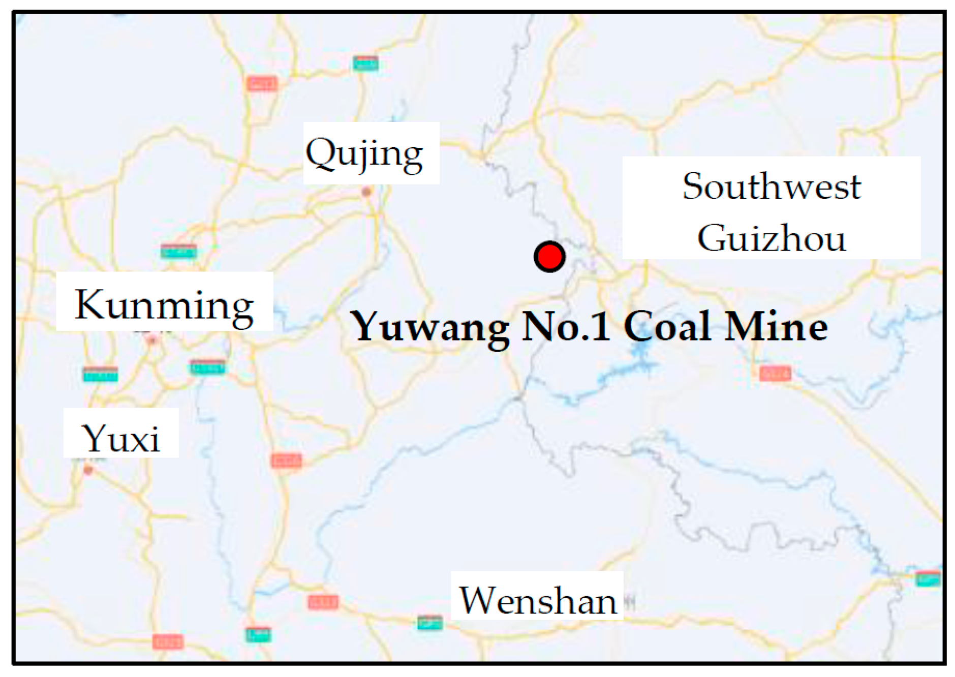
The Yuwang No.1 Coal Mine is a fuel-supporting project for the power plant of the Huaneng Yunnan Yuwang Coal and Power Integration Project, which is one of the “Four Hundred” key construction projects in the Yunnan Province and was started in March 2009. The mine is located in the Yuwang Township, Qujing City, Yunnan Province, approximately 100 km from Fuyuan County, 170 km from Qujing City, and 25 km from the Shankun Expressway (the traffic location is shown in Figure 1). The wellfield is approximately 4.2 km to 10.2 km long and 1.8 km to 7.1 km wide with a wellfield area of 31.75 km2, geological reserves of 653 million tonnes, industrial reserves of 520 million tonnes, design recoverable reserves of 336 million tonnes, a design production capacity of 3 million tonnes/a, and a service life of 79.9 years. The coal seams mined in the field are medium ash, low-to-high sulphur, high calorific value, low phosphorus, exceptionally low chlorine, and good thermal stability No. 3 anthracite coal. The coal-bearing strata in the mine are the Permian Longtan Group and the Changxing Group, with 11 recoverable and partially recoverable coal seams, with a total recoverable coal seam thickness of 32.28 m and mainly stable and relatively stable medium-thick coal seams with a thickness of 2–3 m, which are more suitable for mining. The coal seams are gently buried with a dip angle of 6–15° and moderate layer spacing, making for good resource conditions. Although the coal seams are not spontaneously combustible and have no risk of explosion, the gas content is high and the permeability is low, and there is a risk of coal and gas protrusion, so the technical conditions for mining are complex.
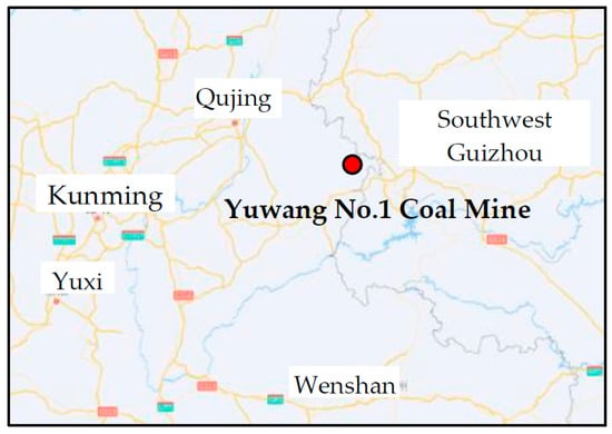
Figure 1.
Schematic diagram of traffic locations.
2.2. Overview of the Working Face
The 1010201 working face is the first working face of the Yuwang No.1 Coal Mine and is also the first back-mining face of the Huaneng Diandong Mine Area. The working face has an elevation of +1535.7~+1254.4 m, corresponding to a surface elevation of +1690~2000 m, and a burial depth of 500~550 m. It belongs to the C2 coal seam, which is the uppermost recoverable coal seam of the Yuwang No.1 Coal Mine, and the average distance between it and the lower recoverable coal seam C3 is 15.17 m. The working face is planned to start back mining in July 2022; the succeeding face is 1,010,202, and the entry to be retained is the track lane of the 1,010,201 working face, which will be reused as the tape lane of the 1,010,202 working face. The design section size of the lane is 5000 mm × 2900 mm driving along the roof of the coal seam, and the working face with roadway retaining is shown in Figure 2.

Figure 2.
Plan of the 1,010,201 working face.
The inclination length of the 1,010,201 working face is 200 m, the strike length is 2271 m, the overall terrain is high on the side of the open cut eye and track lane and low on the side of the stopping line and tape lane, and the average inclination angle is 6°. The entry to be retained can be divided into three sections along the direction of recovery: (1) Upper section: 662 m in total from the open cut eye along the direction of the working face advancement, the coal section. (2) Middle section: 500 m behind the upper section along the working face advancement direction, the rock tunnel section, which is affected by the trap column and cannot be mined. (3) Lower section: 1111 m behind the middle section in the direction of the working face advance, the coal tunnel section. The coal seam thickness of the working face is 0.40–2.41 m, with an average thickness of 1.70 m. Taking into account the gangue, the coal quality, and the equipment selection of the working face, the proposed mining height is 2.4 m, and the mining process is a full-height integrated mining process.
2.3. Engineering Geology
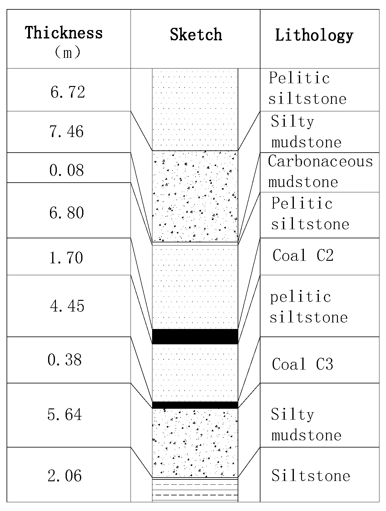
The roof strata of the 1,010,201 first mining face is siltstone, muddy siltstone, and siltstone mudstone, and the bottom strata is siltstone. There are many faults exposed in section channeling and 0~2 layers of gangue in the working face. The lithological column diagram of the Yuwang No.1 Coal Mine is shown in Figure 3, and the lithological situation of the top and bottom strata of the working face is shown in Table 1.
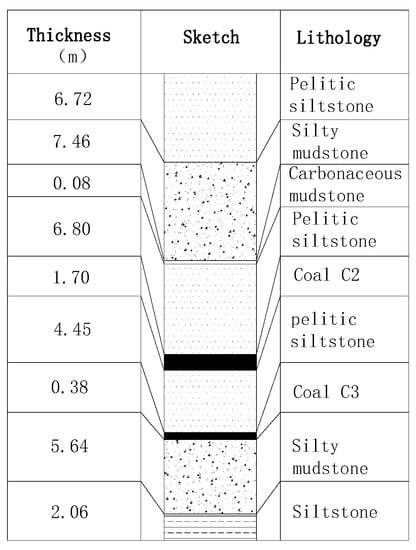
Figure 3.
Lithological column diagram.

Table 1.
Rock properties of the roof and bottom slabs.
In addition, the gas sample of the drilled coal core in the Yuwang No.1 Coal Mine was tested, and it was found that the maximum gas content of the coal seam is 24.78 m3/t, with an average of 9.62 m3/t, which is a high-gas mine. Through field measurements, the C2 coal seam gas pressure is 1.02~1.12 MPa, the solidity coefficient is 0.3~0.6, the coal seam permeability coefficient is 0.000086~0.020972 m2/MPa2d, gas adsorption is strong, extraction is difficult, and in the process of well construction, the C2 coal seam exposure has produced the coal and gas protrusion phenomenon. The mine has been identified as a coal and gas protrusion mine.
The geological characteristics of the Yuwang No.1 Coal Mine are “one soft, one low, two high, and two complex”: (1) One soft: the coal seam is soft. (2) One low: the coal seam has a low permeability and is difficult to extract. (3) Two high: it has a high gas content and a high gas pressure. (4) Two complex: the geological structure is complex. During the coal mine construction period (including drilling, roadway excavation, chamber excavation, and so on), more than 20 faults with a drop of more than 20 m, more than 210 faults with a drop of more than 2 m, and more than 150 faults with a drop of less than 2 m were found. The system is complex; the well field contains 23 coal seams and 11 recoverable coal seams. The coal seams are mined in groups, and mining has a great influence on each other. At present, the mine intends to adopt a top-down “skinning” mining method which includes mining the C2 coal seam as a protective layer, forming pressure relief protection layer by layer, and comprehensive management of gas in the protective layer through surface drilling and a top (bottom) extraction lane through layer drilling and down-seam drilling.
3. Design of Key Parameters
The 110 mining method is a goaf-retaining technology that cuts off the stress transmission between the roadway roof and the goaf roof by directional blasting of the roadway roof and then uses the goaf roof collapse and expansion to realize the roadway reservation after the mining of the working face. It has the advantages of simple retaining technology and a low cost [8,9,10,11,12,13]. Effectively cutting off the stress transfer between the left lane’s roof and the mined-out area’s roof is the key to the entry-retaining technology of roof cutting and pressure relief. Therefore, the design of critical parameters of roof cutting is vital and directly related to the success of the entry retaining. Based on theoretical calculations and engineering experience, this study mainly combines numerical simulation methods to explore the design of critical parameters of the 110 method in the Yuwang No.1 Coal Cine.
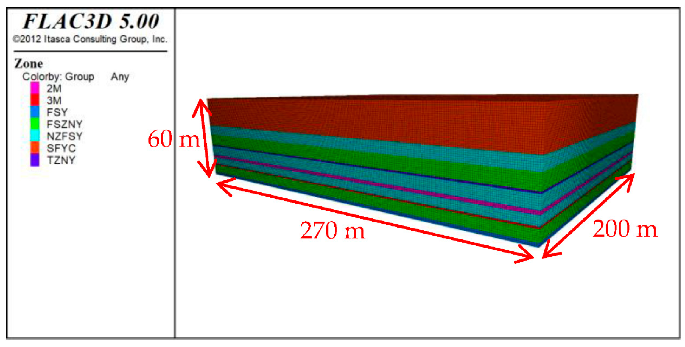
This study analyzes the design of the roof-cutting height and roof-cutting angle of the trackway at the 1,010,201 working face of the Yuwang No.1 Coal Mine with the help of FLAC3D numerical simulation software (version FLAC3D 5.0). First, we established the numerical model of the working face; the lithology and mechanical parameters of the roof and floor of the working face are shown in Table 2 based on the preliminary design of the mine, and the completed 3D model is shown in Figure 4 [19,20]. The length of the model is 270 m in strike, 200 m in tendency, and 60 m in height. The length of the designed mining face is 200 m, and the width of the retrieval tunnel is 5 m. To avoid the influence of excavation disturbances, 30 m boundaries are left on each side of the retrieval tunnel [21,22]. Based on the actual engineering conditions of the test working face and the proper simplification of calculations, this research established a three-dimensional calculation model based on the Mohr–Coulomb constitutive model. Constraints are set on the left and right boundary as well as the lower boundary of the model. A vertical stress of 8.6 MPa was loaded on the upper boundary to simulate the self-weight pressure of the overburdened rock above the underground stope [23,24]. After the original rock stress was loaded and balanced, tunnel excavation and roof-cutting simulations were conducted, and calculations and analysis of stress, strain, and the plastic zone distribution were carried out.

Table 2.
Rock property parameters of the roof and bottom slabs.
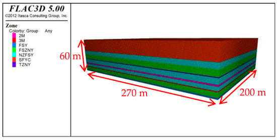
Figure 4.
Three-dimensional numerical model.
3.1. Roof-Cutting Height
3.1.1. Preliminary Design
According to the industry standard “Code for No-pillar Mining with Gob-entry Retaining of the 110 Mining Method”, the critical height of the roof presplitting (HF) is calculated by the following formula [25]:
where HM—mining height, m; △H1—roof subsidence volume, m; △H2—bottom drum volume, m; K—coefficient of crushing expansion, 1.3~1.5.
HF = (HM − △H1 − △H2)/(K − 1)
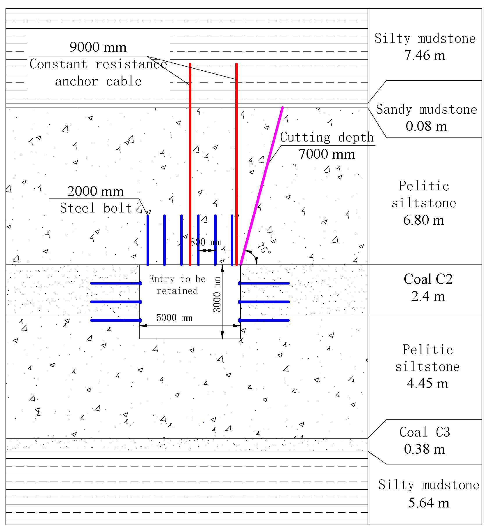
Combining engineering experience with the lithology of the 1,010,201 working face roof, the value of K was taken as 1.35. According to the drilling data, the thickness of the coal seam changes little. Without considering the floor heave and roof subsidence for the first time to apply the 110 mining method conservatively, the maximum mining height of the working face was taken as 2.4 m, and the critical height of roof presplitting cutting is 6.86 m. To facilitate construction, the depth of the roof cutting hole was taken as 7.0 m, as shown in Figure 5.
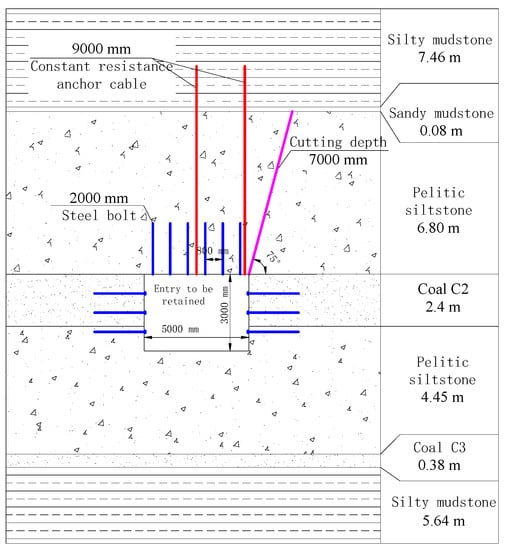
Figure 5.
Roof-cutting design drawing.
3.1.2. Numerical Simulation Validation
To analyze the effect of different roof-cutting height designs on the pressure relief effect of roof cutting and to verify the reasonableness of the roof-cutting parameters, we used a numerical simulation to analyze the pressure relief effect.
- (1)
- Vertical stress distribution law at different roof-cutting heights
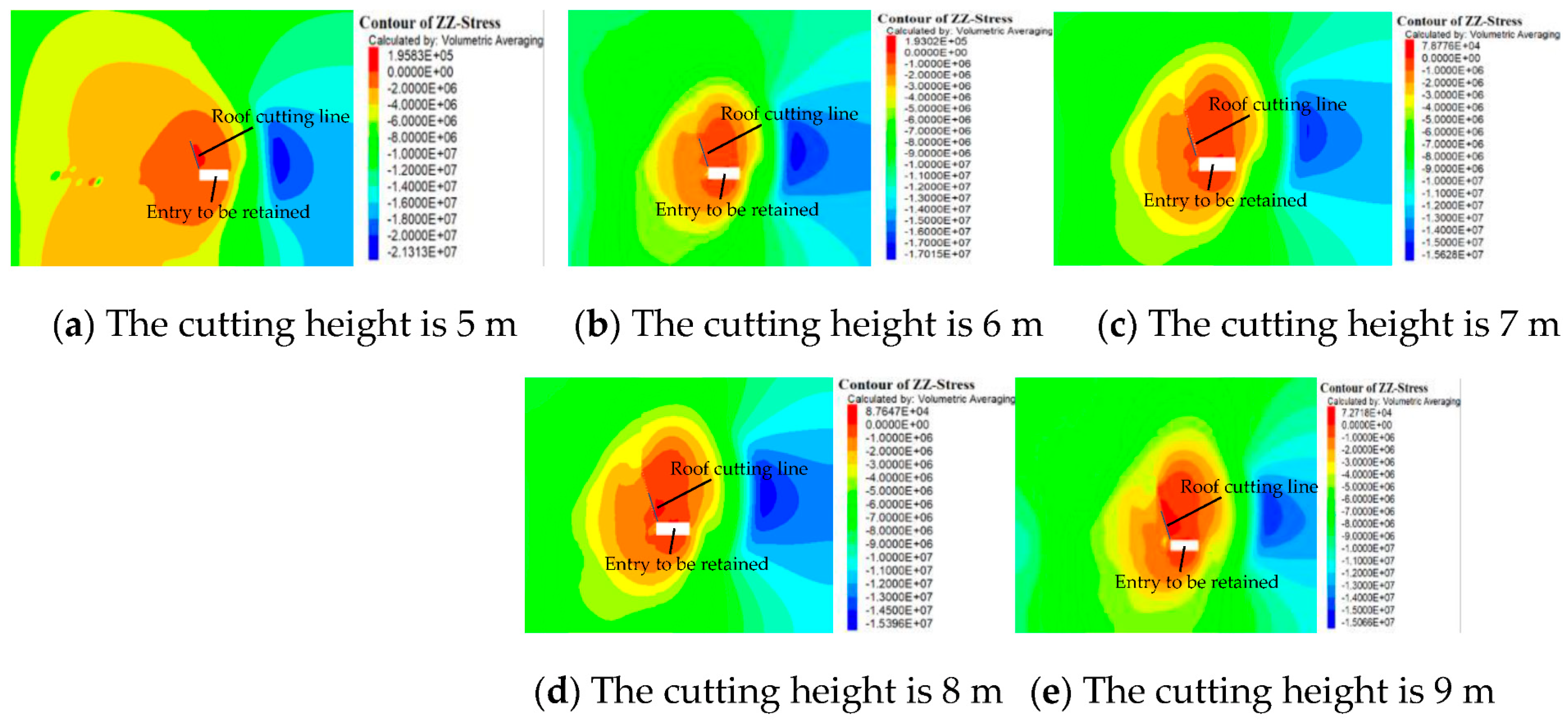
With the help of FLAC 3D numerical simulation software (version FLAC3D 5.0), we simulated the roof-cutting depth of 5 m, 6 m, 7 m, 8 m, and 9 m, respectively, and the simulation and theoretical calculation results were verified with each other to obtain the best cutting height. The vertical stresses in the tunnel surrounding rock under different roof-cutting height conditions are shown in Figure 6.
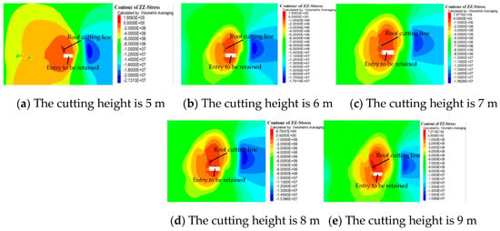
Figure 6.
Vertical stress distribution of roadway surrounding rock under different cutting heights.
As can be seen from Figure 6, when the roof-cutting depth is 5 m, the maximum vertical stress is 21.3 MPa, and the stress concentration area is about 7.5 m from the roadway; when the roof-cutting depth is 6 m, the maximum vertical stress is 17.0 MPa, and the stress concentration area is about 8.1 m from the roadway; when the roof-cutting depth is 7 m, the maximum vertical stress is 15.6 MPa, and the stress concentration area is about 8.5 m from the roadway. It is evident that with the increasing height of the roof cutting, the vertical stress peak decreases, and the stress concentration area becomes farther and farther from the roadway, indicating that with an appropriate increase in the roof-cutting height, the effect of the roof-cutting pressure relief becomes better and better. Compared with the roof-cutting depth of 5 m, the peak vertical stress is reduced by 20.2% when the height of roof cutting is 6 m, 26.8% when the roof-cutting depth is 7 m, 28.2% when the roof-cutting depth is 8 m, and 29.1% when the roof-cutting depth is 9 m, which shows that the peak vertical stress is reduced when the roof-cutting depth increases from 5 m to 7 m. When the depth of the slit is increased to 8 m and 9 m, the vertical stress peak is still reduced, but the reduction is smaller. Considering the amount of construction work and the loss of labor and materials, the optimized height of roof cutting was determined to be 7 m.
- (2)
- Horizontal stress distribution at different roof-cutting heights
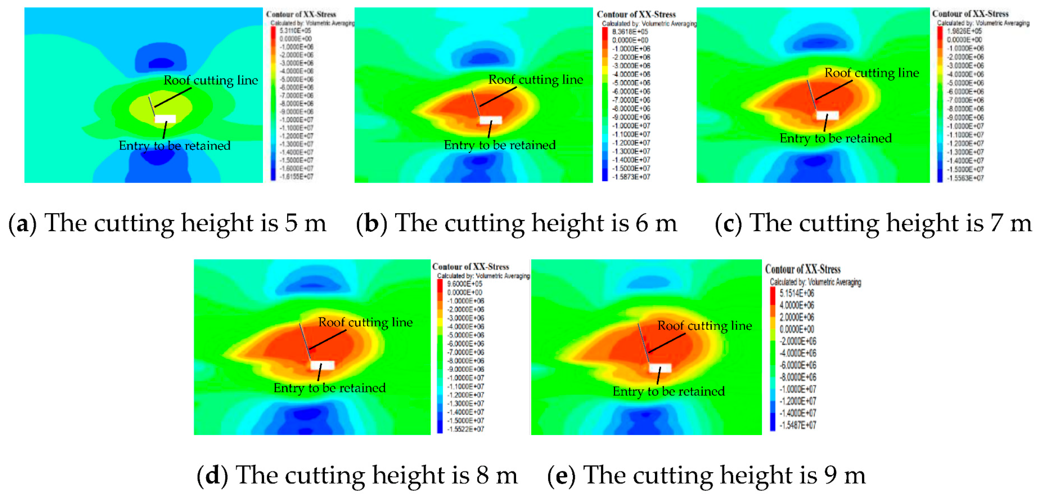
The horizontal stress distributions of the tunnel surrounding rock under different roof-cutting heights are shown in Figure 7.
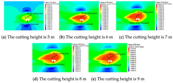
Figure 7.
Horizontal stress distribution of roadway surrounding rock under different cutting heights.
As can be seen from Figure 7, the maximum value of the horizontal stress is 16.16 MPa when the depth of roof cutting is 5 m, 15.87 MPa when the depth of roof cutting is 6 m, 15.56 MPa when the depth of roof cutting is 7 m, 15.52 MPa when the depth of roof cutting is 8 m, and 15.49 MPa when the depth of roof cutting is 9 m. The results show that the greater the roof-cutting depth is, the lower the peak value of the horizontal stress will be, and the better the roof-cutting pressure relief effect will be. Compared with the roof-cutting depth of 5 m, the peak horizontal stress is reduced by 1.75% when the roof-cutting depth increases to 6 m, 3.66% when the roof-cutting depth increases to 7 m, 3.92% when the roof-cutting depth increases to 8 m, and 4.13% when the roof-cutting depth increases to 9 m. By comparison, we found that when the cutting depth increased from 5 m to 7 m, the peak horizontal stress decreased more obviously. After the roof-cutting depth increased to 8 m and 9 m, the peak horizontal stress was still decreased, but the decrease was smaller. Considering the amount of construction work and the loss of labor and materials, the optimized height of roof cutting was determined to be 7 m.
- (3)
- Vertical displacement at different roof-cutting heights
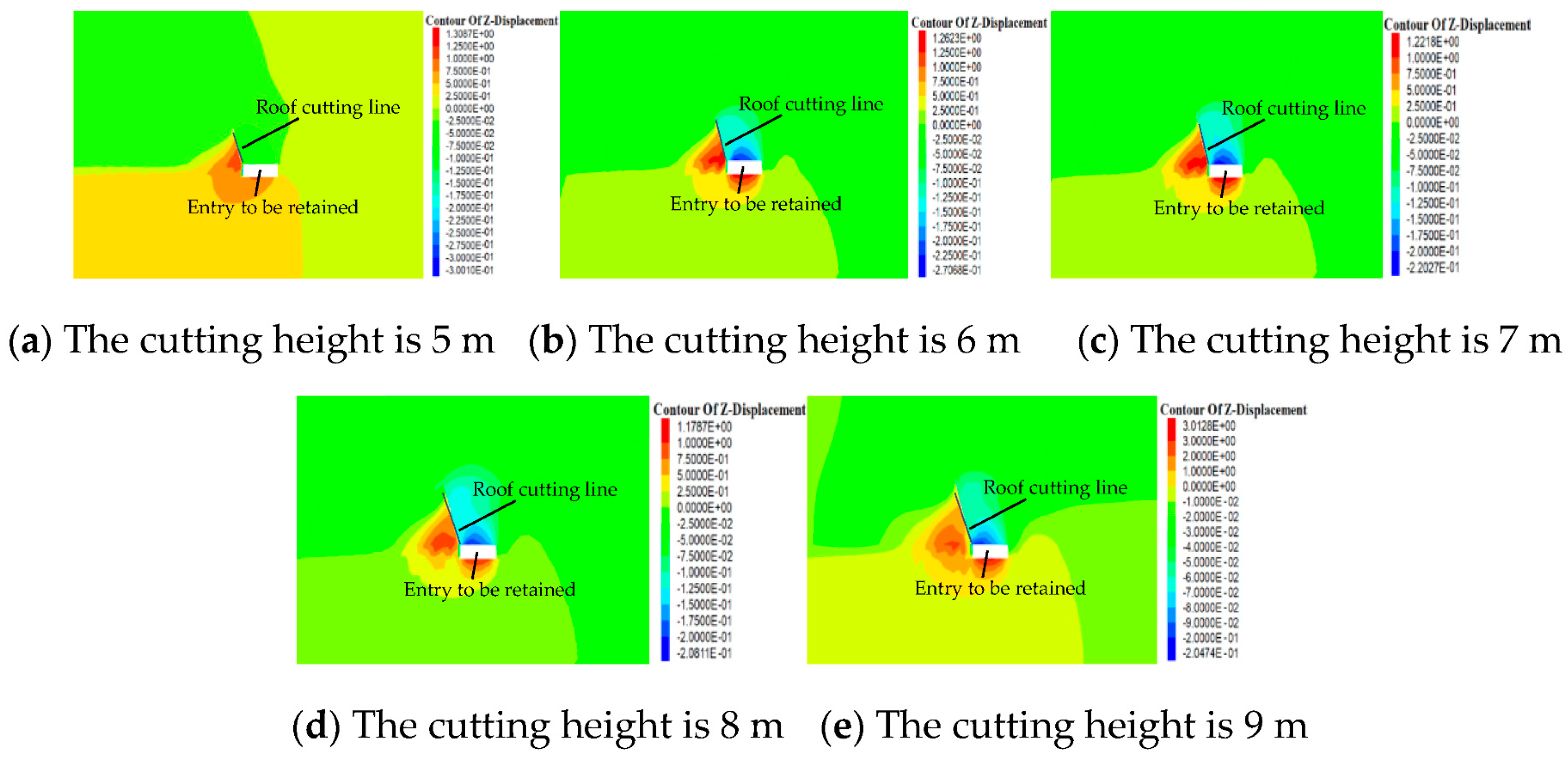
The vertical displacement of the tunnel surrounding rock under different roof-cutting height conditions is shown in Figure 8.
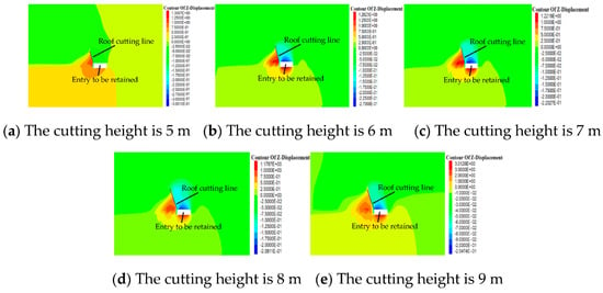
Figure 8.
Vertical displacement of roadway surrounding rock under different cutting heights.
As can be seen from Figure 8, the maximum value of the vertical displacement is 300.1 mm when the depth of roof cutting is 5 m, 270.7 mm when the depth of roof cutting is 6 m, 220.3 mm when the depth of roof cutting is 7 m, 208.1 mm when the depth of roof cutting is 8 m, and 204.7 mm when the depth of roof cutting is 9 m. The results show that the maximum value of the vertical displacement becomes smaller and smaller with the increase in the roof-cutting depth, which indicates that the effect of unloading pressure from roof cutting is positively correlated with the roof-cutting depth. Compared with the roof-cutting depth of 5 m, when the roof-cutting depth is 6 m, the maximum vertical displacement decreases by 9.8%, when the roof-cutting depth is 7 m, the maximum vertical displacement decreases by 26.6%, when the roof-cutting depth is 8 m, the maximum vertical displacement decreases by 30.7%, and when the roof-cutting depth is 9 m, the maximum vertical displacement decreases by 31.8%. Through comparison, it was found that when the roof cutting depth increases from 5 m to 7 m, the maximum vertical displacement decreases significantly, while when the roof cutting depth increases to 8 m and 9 m, the maximum vertical displacement still decreases, but the reduction is small. Considering the amount of construction work and the loss of labor and materials, the optimized height of roof cutting was determined to be 7 m.
- (4)
- Horizontal displacement at different roof-cutting heights
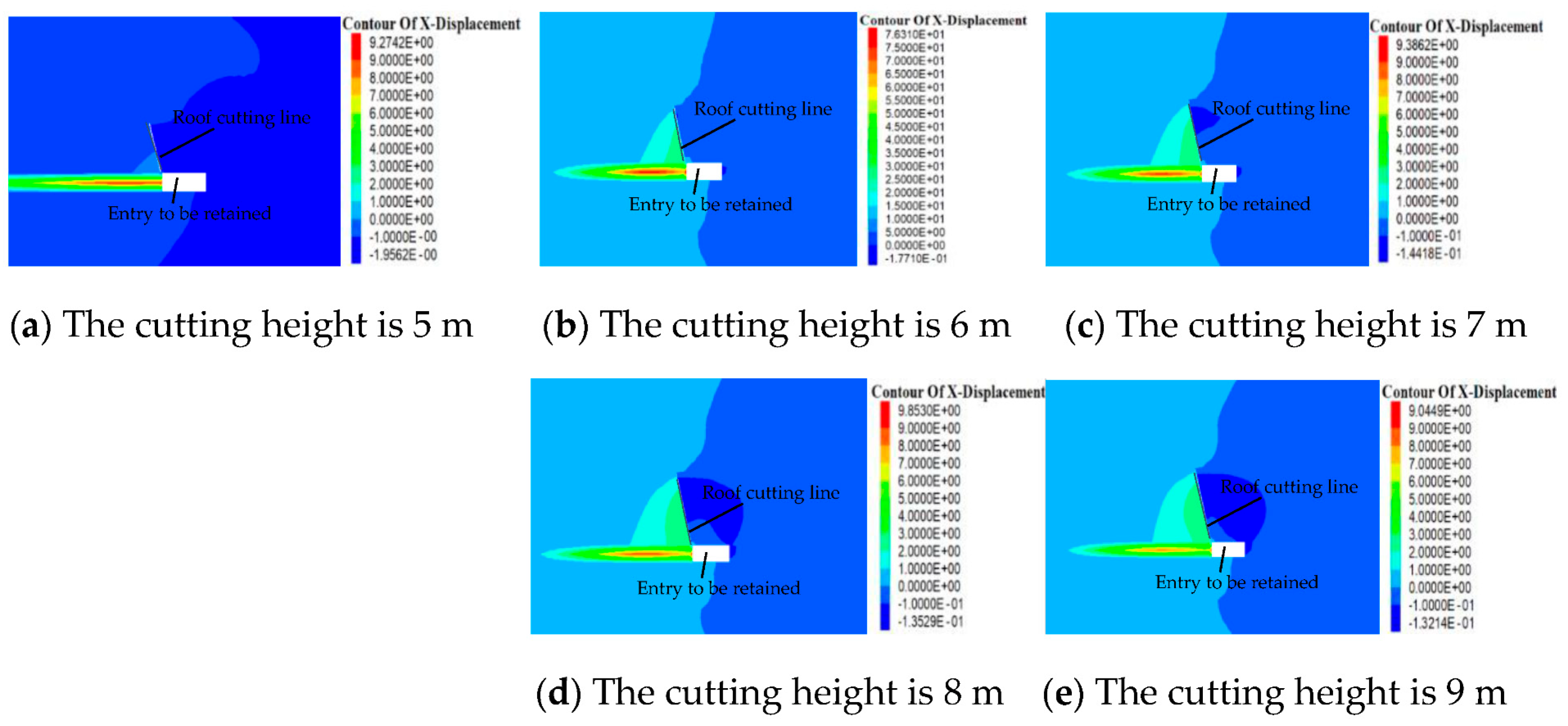
The horizontal displacement of the tunnel surrounding rock under different roof-cutting height conditions is shown in Figure 9.
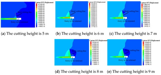
Figure 9.
Horizontal displacement of roadway surrounding rock under different cutting heights.
As can be seen from Figure 9, the maximum value of the horizontal displacement is 195.62 mm when the depth of roof cutting is 5 m, 177.10 mm when the depth of roof cutting is 6 m, 144.18 mm when the depth of roof cutting is 7 m, 135.29 mm when the depth of roof cutting is 8 m, and 132.14 mm when the depth of roof cutting is 9 m. The results show that with an increase in the roof-cutting depth, the maximum value of the horizontal displacement is smaller, indicating that the effect of pressure relief of roof cutting is positively related to the roof-cutting depth. Compared with the roof-cutting depth of 5 m, when the roof-cutting depth is 6 m, the maximum horizontal displacement decreases by 9.5%, when the roof-cutting depth is 7 m, the maximum horizontal displacement decreases by 26.3%, when the roof-cutting depth is 8 m, the maximum horizontal displacement decreases by 30.84%, and when the roof-cutting depth is 9 m, the maximum horizontal displacement decreases by 32.45%. By comparison, it can be found that when the depth of roof cutting increases from 5 m to 7 m, the maximum horizontal displacement decreases more obviously, and when the depth of roof cutting increases to 8 m and 9 m, the maximum horizontal displacement still decreases, but the decrease is smaller. Considering the amount of construction work and the loss of labor and materials, the optimized height of roof cutting was determined to be 7 m.
- (5)
- The range of the plastic zone with different roof-cutting heights
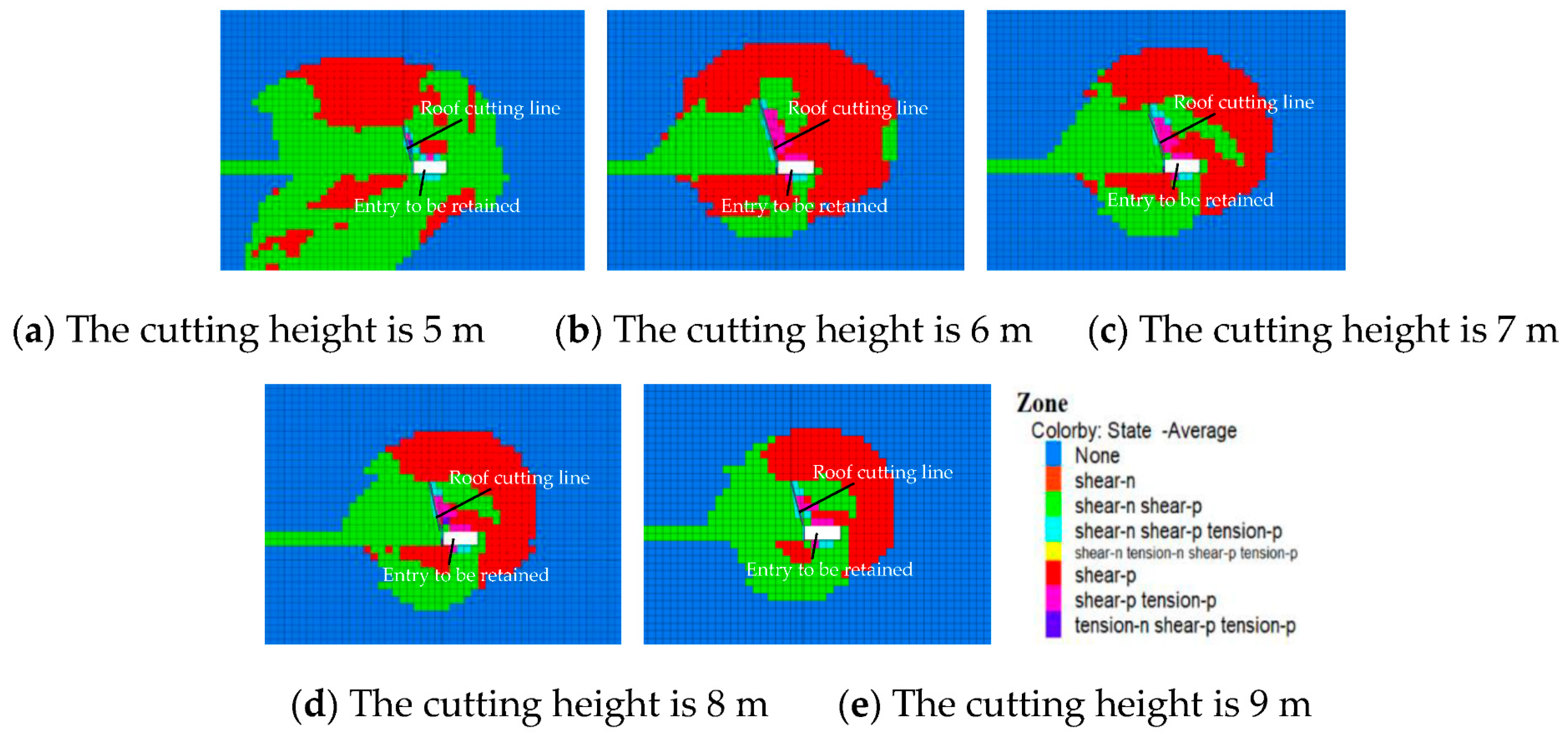
The extent of the plastic zone of the roadway surrounding rock under different roof-cutting height conditions is shown in Figure 10.
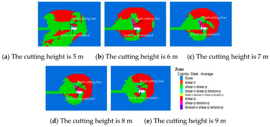
Figure 10.
Plastic zone of roadway surrounding rock under different cutting heights.
As can be seen from Figure 10, when the roof-cutting depth is 5 m or 6 m, the roof-cutting depth is small, which cannot completely cut off the stress transfer path, and the roof-cutting pressure relief effect is poor, so the range of the plastic zone of the entry surrounding rock is larger after the workface is mined. With an increase in the roof cutting depth to 7~9 m, it can effectively cut off the stress transfer path and force the stress to transfer to the depth of the coal body. Compared with the cutting depth of 5 m and 6 m, the effect of roof cutting and pressure relief is more obvious, and the range of the plastic zone of the surrounding rock is also obviously reduced. However, the change in the plastic zone of the surrounding rock is not obvious when the depth of the cut is from 7 m to 9 m, so the best depth of cut is 7 m from the perspective of reducing the construction volume and the cost of labor and material.
In conclusion, the optimal depth of entry-retaining roof cutting is 7 m from the perspective of vertical stress, horizontal stress, vertical displacement, horizontal displacement, the plastic zone range of the surrounding rock, engineering volume, and construction cost.
3.2. Roof-Cutting Angle
3.2.1. Preliminary Design
According to the industry standard “Code for No-pillar Mining with Gob-entry Retaining of the 110 Method” [25] combined with the mining height conditions of the Yuwang No.1 Coal Mine, it was designed that the entry-retaining roof-cutting hole is to be arranged at the angle between the entry wall and the roof, and the included angle between the roof-cutting hole and the plumb line is 15°, as shown in Figure 5.
3.2.2. Numerical Simulation Validation
To analyze the effect of different roof-cutting angle designs on the pressure relief effect of roof cutting and to verify the reasonableness of the roof-cutting parameters, the pressure relief effect was analyzed by numerical simulation.
- (1)
- Vertical stress at different roof-cutting angles
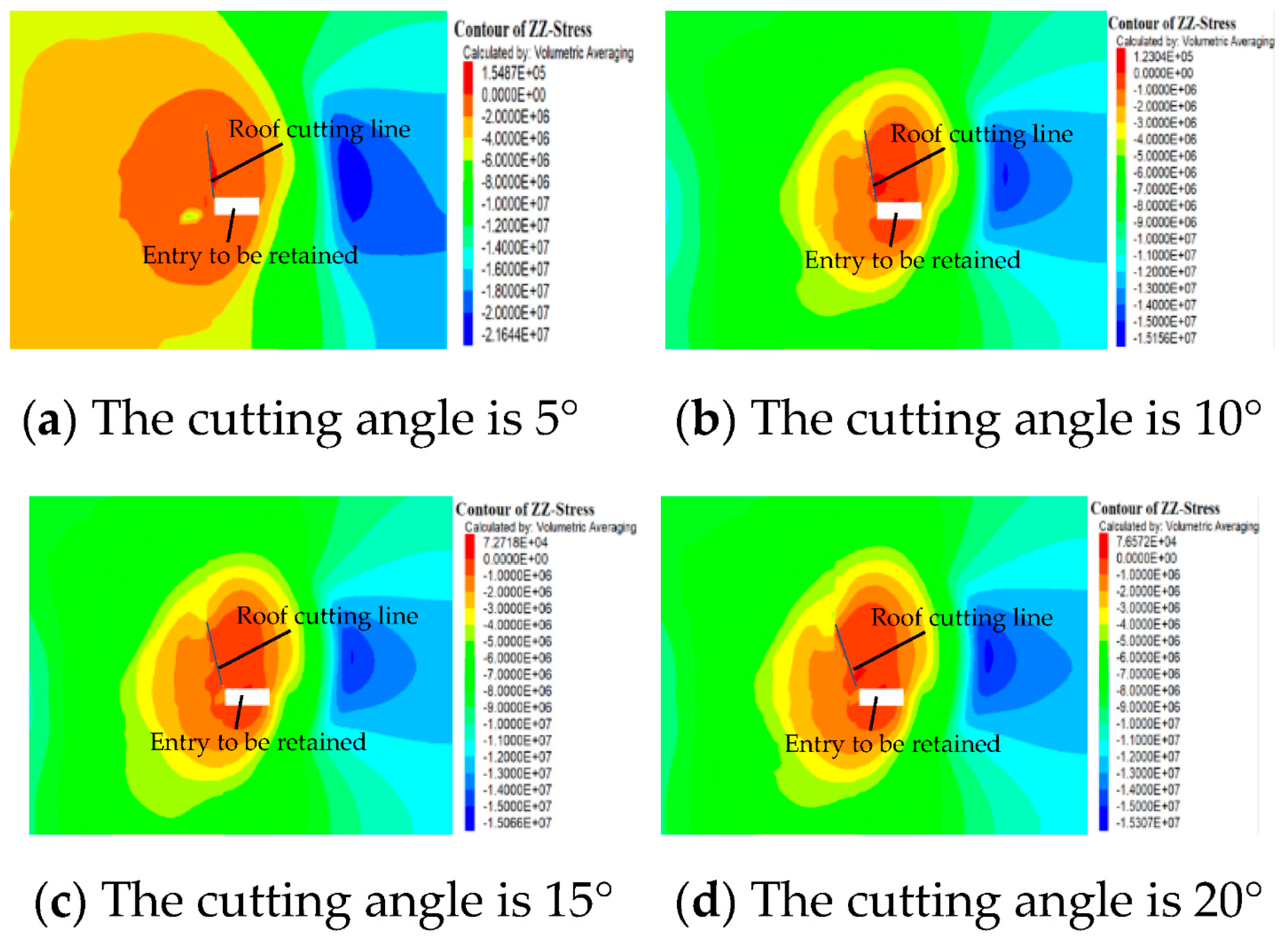
With the help of FLAC3D numerical simulation software (version FLAC3D 5.0), the roof-cutting angles of 5°, 10°, 15°, and 20° were simulated, respectively, and the simulation and theoretical calculation results were verified with each other to obtain the best roof-cutting angle. The vertical stress distributions of the entry surrounding rock under different roof-cutting angle conditions are shown in Figure 11.
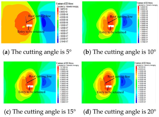
Figure 11.
Vertical stress of roadway surrounding rock under different cutting angles.
As can be seen from Figure 11, when the roof-cutting angle is 5°, the maximum vertical stress is 21.64 MPa, and the stress concentration area is about 7.5 m from the roadway; when the roof-cutting angle is 10°, the maximum vertical stress is 15.15 MPa, and the stress concentration area is about 8.1 m from the roadway; when the roof-cutting angle is 15°, the maximum vertical stress is 15.06 MPa, and the stress concentration area is about 8.5 m from the roadway; when the roof-cutting angle is 20°, the maximum vertical stress is 15.30 MPa, and the stress concentration area is about 8.6 m from the roadway. From the perspective of vertical stress, the best angle for roof cutting is 15°.
- (2)
- Horizontal stress at different cutting angles
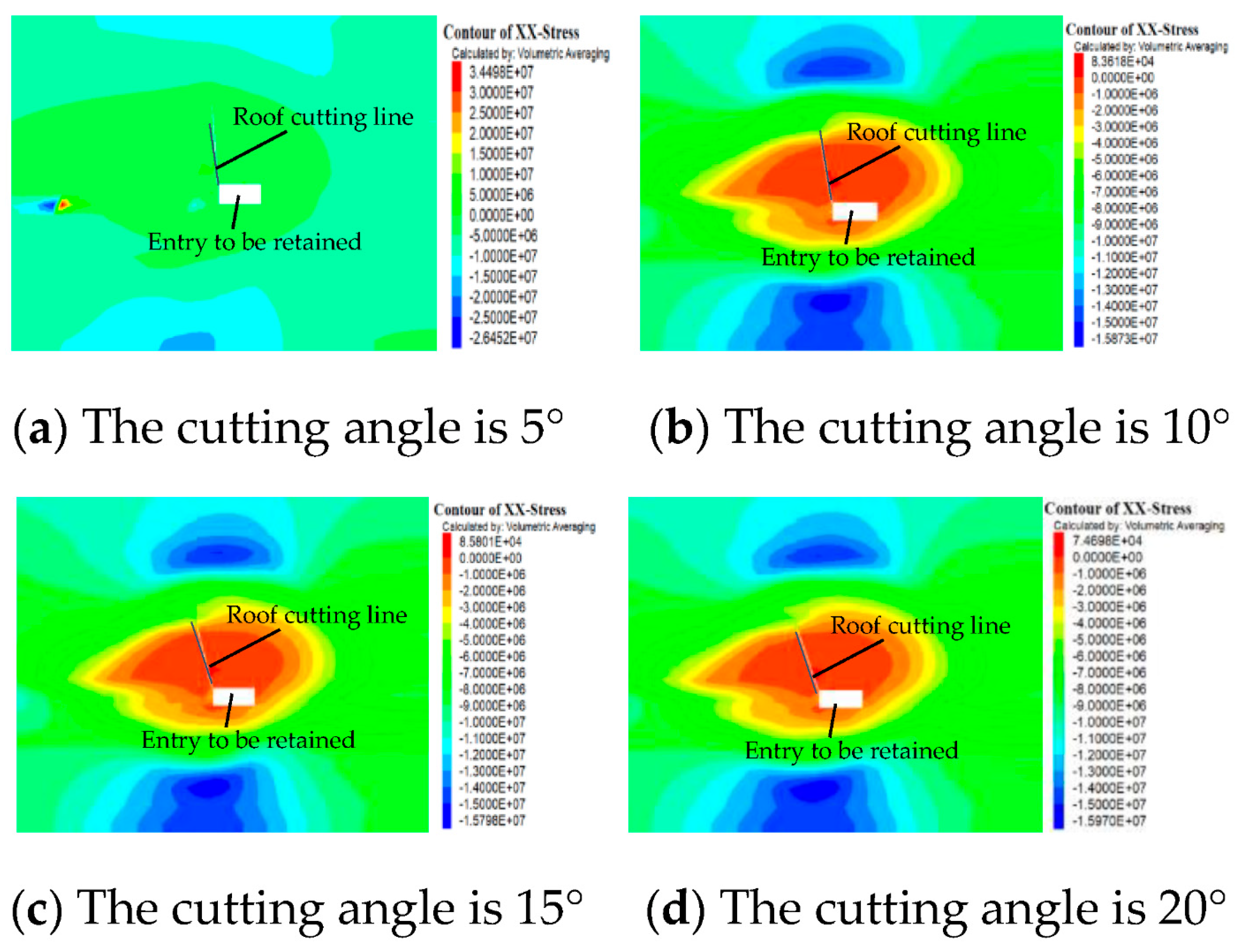
The horizontal stress distributions of the entry surrounding rock under different cutting angle conditions are shown in Figure 12.
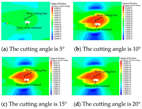
Figure 12.
Horizontal stress of roadway surrounding rock under different cutting angles.
As can be seen from Figure 12, the maximum horizontal stress is 26.45 MPa when the roof-cutting angle is 5°, 15.87 MPa when the roof-cutting angle is 10°, 15.79 MPa when the roof-cutting angle is 15°, and 15.97 MPa when the roof-cutting angle is 20°. The results show that the peak horizontal stress is smaller when the roof-cutting angle is larger at the beginning. The larger the angle of roof cutting, the smaller the peak horizontal stress, indicating that with an appropriate increase in the angle of roof cutting, the effect of roof cutting and the pressure relief become better and better. However, when the angle of roof cutting exceeds 15°, the peak horizontal stress increases instead of decreasing, indicating that a larger angle of roof cutting is not better. If the angle of roof cutting is too large, the rock layer on the roof of the roadway is not easy to collapse, and it affects the effect of roof cutting and pressure relief. Therefore, from the perspective of horizontal stress, the best angle of roof cutting is 15°.
- (3)
- Vertical displacement of different roof-cutting angles
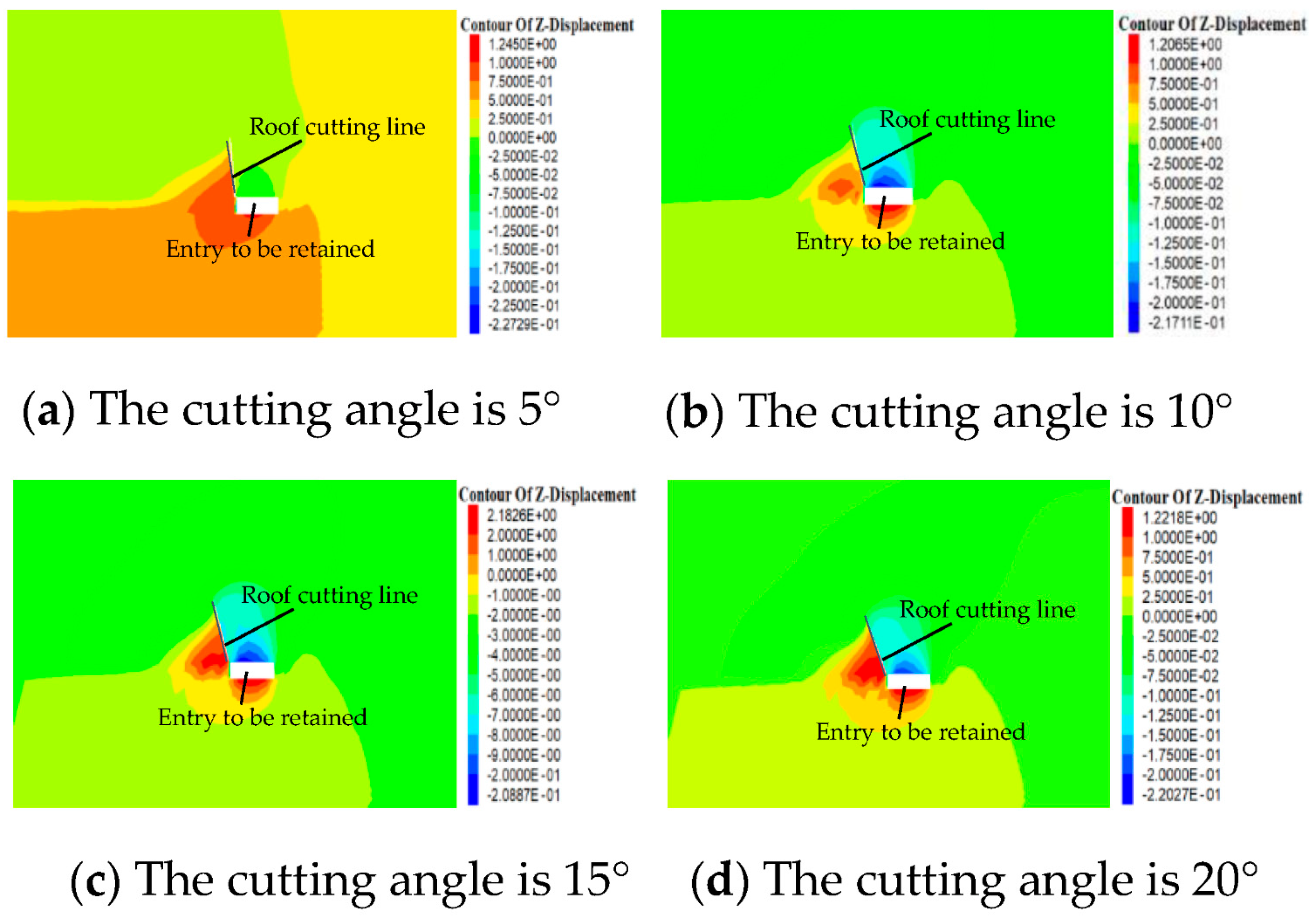
The vertical displacement of the roadway surrounding rock under different roof-cutting angles is shown in Figure 13.
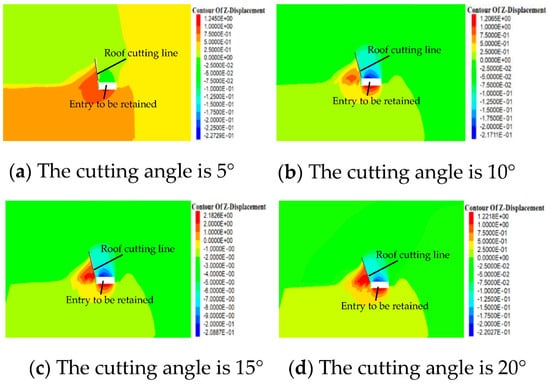
Figure 13.
Vertical displacement of surrounding rock of the roadway under different cutting angles.
As can be seen from Figure 13, the maximum value of the vertical displacement is 220.27 mm when the roof-cutting angle is 5°, 217.11 mm when the roof-cutting angle is 10°, 208.87 mm when the roof-cutting angle is 15°, and 227.29 mm when the roof-cutting angle is 20°. The results show that if the roof-cutting angle is too small, the broken roof rock cannot easily form a stable articulation structure, which leads to a large vertical displacement in the roadway. However, if the roof-cutting angle is too large, the roof rock is not easy to collapse and cannot play a good role in roof cutting and pressure relieving. Therefore, from the perspective of vertical displacement, the best roof-cutting angle is 15°.
- (4)
- Horizontal displacement of different cutting angles
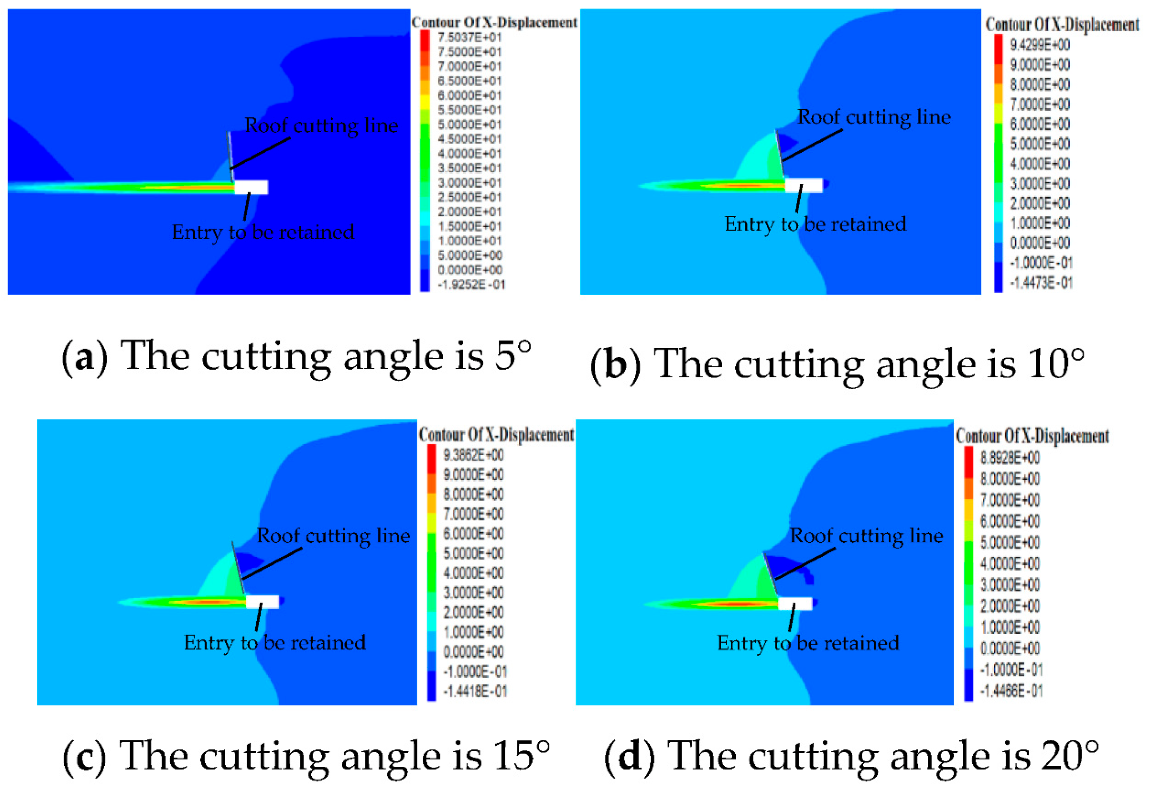
The horizontal displacement of the surrounding rock of the roadway under different roof-cutting angles is shown in Figure 14.
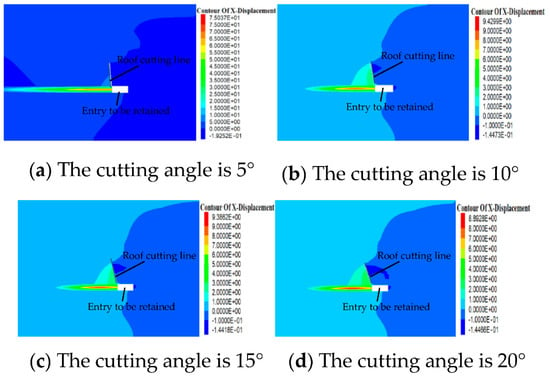
Figure 14.
Horizontal displacement of roadway surrounding rock under different cutting angles.
As can be seen from Figure 14, the maximum horizontal displacement is 192.52 mm when the roof-cutting angle is 5°, 144.73 mm when the roof-cutting angle is 10°, 144.18 mm when the roof-cutting angle is 15°, and 144.66 mm when the roof-cutting angle is 20°. The results show that with an appropriate increase in the roof-cutting angle, the roof-cutting pressure relief effect becomes better and better, but when the roof-cutting angle exceeds 15°, the horizontal displacement peak of the roadway increases instead of decreasing. Therefore, from the perspective of the horizontal displacement of the roadway surrounding rock, the best roof-cutting angle is 15°.
- (5)
- The range of the plastic zone at different roof-cutting angles
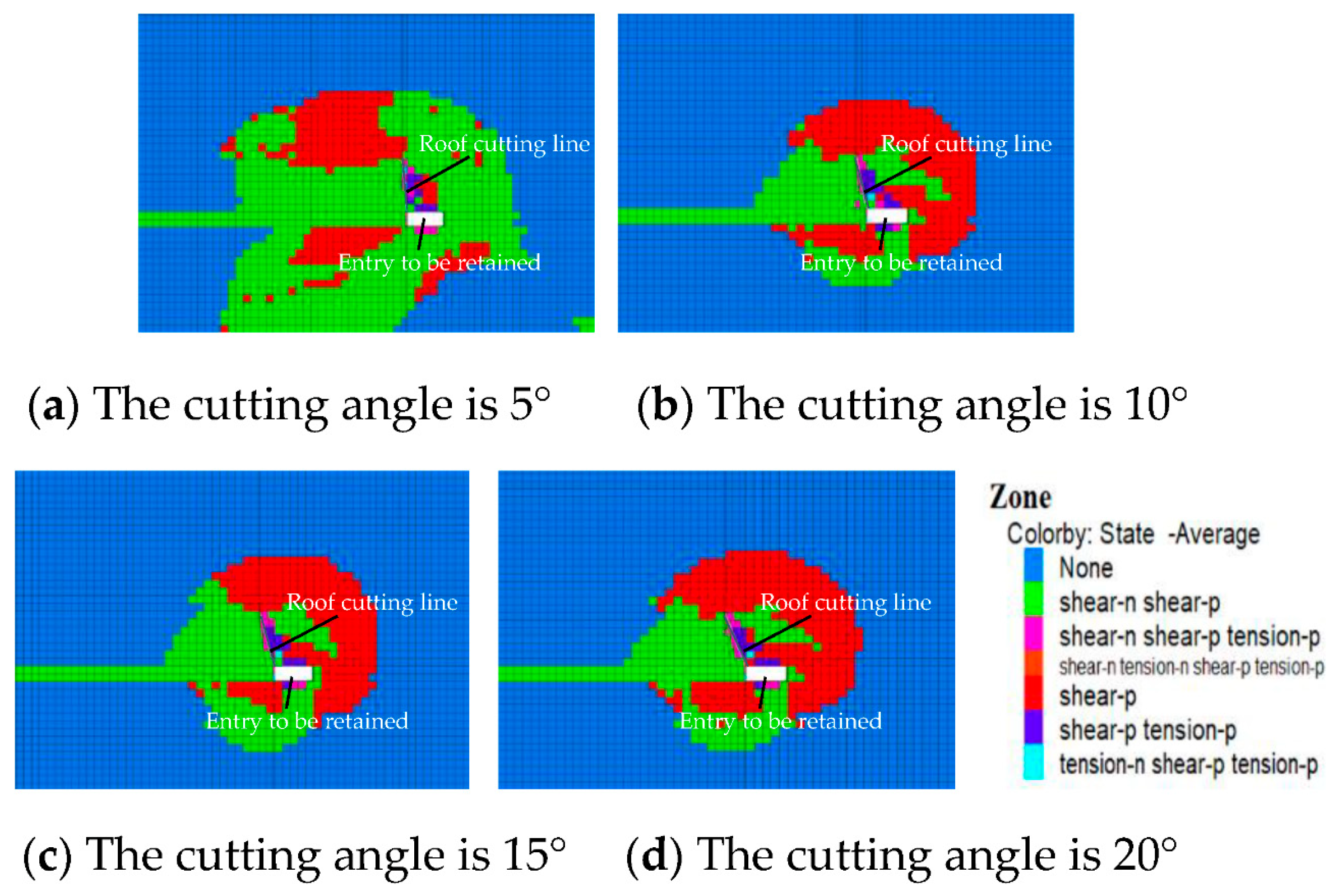
The range of the plastic zone of the surrounding rock of the roadway under different roof-cutting angles is shown in Figure 15.
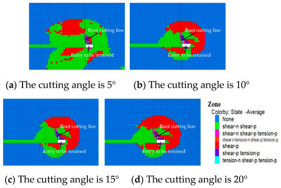
Figure 15.
Plastic zone range of the surrounding rock of the roadway under different cutting angles.
As can be seen from Figure 15, when the roof-cutting angle is 5°, due to the small roof-cutting angle, the broken roof rock cannot easily form a stable articulation structure and is more likely to be destabilized, so the plastic zone of the roadway surrounding rock is larger after the working face mining. When the roof-cutting angle is 10°, with an increase in the roof-cutting angle, the broken roof slab can form a more stable articulation structure, which improves the mechanical environment of the roadway surrounding rock and has a good effect on roof cutting and pressure relieving, and the plastic zone is reduced. When the roof-cutting angle is 15°, the mechanical environment of the roadway surrounding rock is further improved, and the plastic zone is further reduced. When the roof-cutting angle is 20°, compared with the roof-cutting angle of 15°, the plastic zone of the roadway surrounding rock does not decrease but slightly increases, indicating that the roof-cutting angle is too large, which increases the influence of disturbances on the roadway surrounding rock. Therefore, from the perspective of the plastic zone, the optimal roof-cutting angle is 15°.
In summary, from the perspective of vertical stress, horizontal stress, vertical displacement, horizontal displacement, and the plastic zone range of the roadway surrounding rock, when the roof-cutting angle is 15°, the peak stress, displacement, and the plastic zone range of the surrounding rock are the smallest, so the best angle for the design of the roof cutting of the Yuwang No.1 Coal Mine is 15°.
3.3. Blasting Parameters
After the height and the angle of entry of the roof cutting are determined, two-way-shaped charge cutting technology is needed to blast the roof, and the design of the blast hole spacing and charge quantity is usually determined by numerical simulation and field-blasting tests. Considering that the actual blasting test conditions were unavailable at the site, this paper adopted a numerical simulation method to conduct a preliminary design of the blasting parameters, first, and then carried out an on-site roof-cutting blasting test for verification when the site conditions were mature.
3.3.1. Blast Modeling
The roof-cutting blast parameter simulation was analyzed by LS-DYNA software (version LS-DYNA R11.1.0), which is a general finite element nonlinear dynamic analysis program, and it is good at solving various 2D and 3D nonlinear problems. To avoid solution anomalies due to excessive deformation of explosive and air cells during the calculation, the multi-matter ALE algorithm, which is suitable for dealing with large deformation problems, was used in this calculation [26,27]. In this algorithm, the grid points can move with the material points, but they can also be fixed in space, and the grid points can even be fixed in one direction and move with the material points in the other direction. For the convenience of calculation, the simulation takes the charge profile of energy accumulation blasting as the calculation object. It uses a single-layer grid of the planar stress model for computation. The relevant blasting model was established according to the 1:1 scale according to the actual site of the Yuwang No.1 Coal Mine.
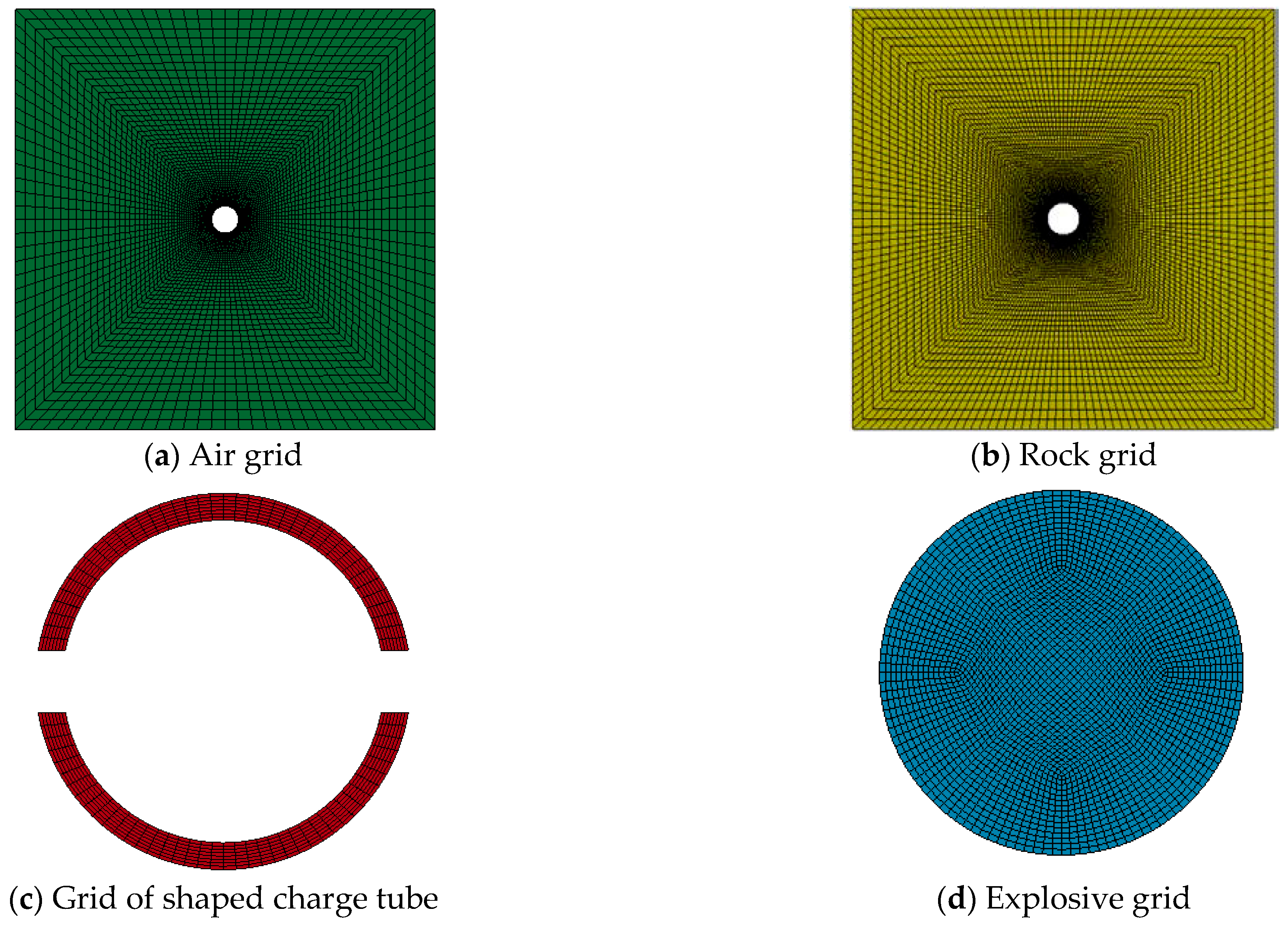
The numerical model of blasting is shown in Figure 16. The model consists of a rock unit, an air unit, an explosive unit, and a shaped charge tube unit, and the size of the shaped charge tube model is the same as in the actual project, with an inner diameter of 3.6 cm, an outer diameter of 4.2 cm, and cut width of 0.4 cm. The diameter of the explosive is 3.2 cm. The calculation model was simplified to a plane stress state, and 0.5 cm was taken in the thickness direction. The explosive was used in the calculation process. The air boundary condition was set to a nonreflective boundary condition. In order to reveal the effect of the shaped charge, another blasting model with the same size and the same parameters, except for having no shaped charge tube, was established for comparative analysis.

Figure 16.
Blasting numerical model.
The simulation model uses 164 solid cells and the mapped meshing method, and the grid cell is shown in Figure 17. Local grid refinement is conducive to transferring blast pressure, so the air and rock grid refinement is at the area near the explosives. The grid quality of the shaped charge tube and explosive has no obvious influence on the simulation effects, so the grid was no longer refined but was divided into uniform grids.
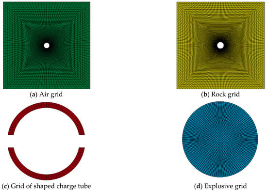
Figure 17.
Model meshing.
The material parameters of the simulation unit were selected as follows:
- (1)
- Explosives
The explosive material model uses MAT_HIGH_EXPLO_SIVE_BU_RN, and the model uses the JWL (Jones–Wilkins–Lee) equation of state after the detonation of the explosive to describe the pressure–volume relationship of the detonation products [28,29]:
where P—pressure; V—burst products’ relative volume; E0—specific internal energy; A, B, R1, R2, ω—material constants.
A class III emulsion explosive for coal mines was used as the explosive, and the explosive parameters and the JWL state equation parameters are shown in Table 3.

Table 3.
Explosive parameters.
- (2)
- Rocks
The Johnson–Holmquist model was used to study the crack growth process of the rock in the process of shaped charge blasting under explosive loads. The rock parameters were determined according to the physical and mechanical properties of argillaceous siltstone in the 1,010,201 working face of the Yuwang No.1 Coal Mine.
- (3)
- Shaped charge tube
The energy-gathering material is PVC pipe. The main role of the PVC pipe in the bidirectional energy-gathering tension blasting is to produce the energy-gathering tension effect in the energy-gathering direction (the side of the energy-gathering hole). Since the explosion is a very short process, the phase change (vaporization) in the PVC pipe occurs after the rock generates tension cracks. At this time, the PVC pipe has little influence on the crack expansion. In this period, the tensile stress produced by high-pressure detonation gas on the detonation cracks and its gas wedge effect have a greater impact on the crack growth. Therefore, the plastic follow-up model was selected for the constitutive equation of the PVC pipe (shaped charge pipe). Specific parameters of the shaped charge materials are shown in Table 4.

Table 4.
Mechanical parameters of the shaped energy pipe.
- (4)
- Air
Since the shaped charge tube does not fully fit the blast hole wall, the air area should be set. Considering air as an ideal gas and applying the MAT_NULL material and LINEAR POLYNOMIAL state equations to express it, the air parameters are shown in Table 5.

Table 5.
Air parameters.
3.3.2. Numerical Simulation Analysis
- (1)
- Numerical analysis of single-hole blasting
By comparing and analyzing the stress evolution law and the development law of blasting cracks between single-hole non-shaped charge blasting and single-hole shaped charge blasting, the cumulative effect of shaped charge blasting was obtained.
(1) Detonation stress and crack analysis of single-hole non-shaped charge blasting
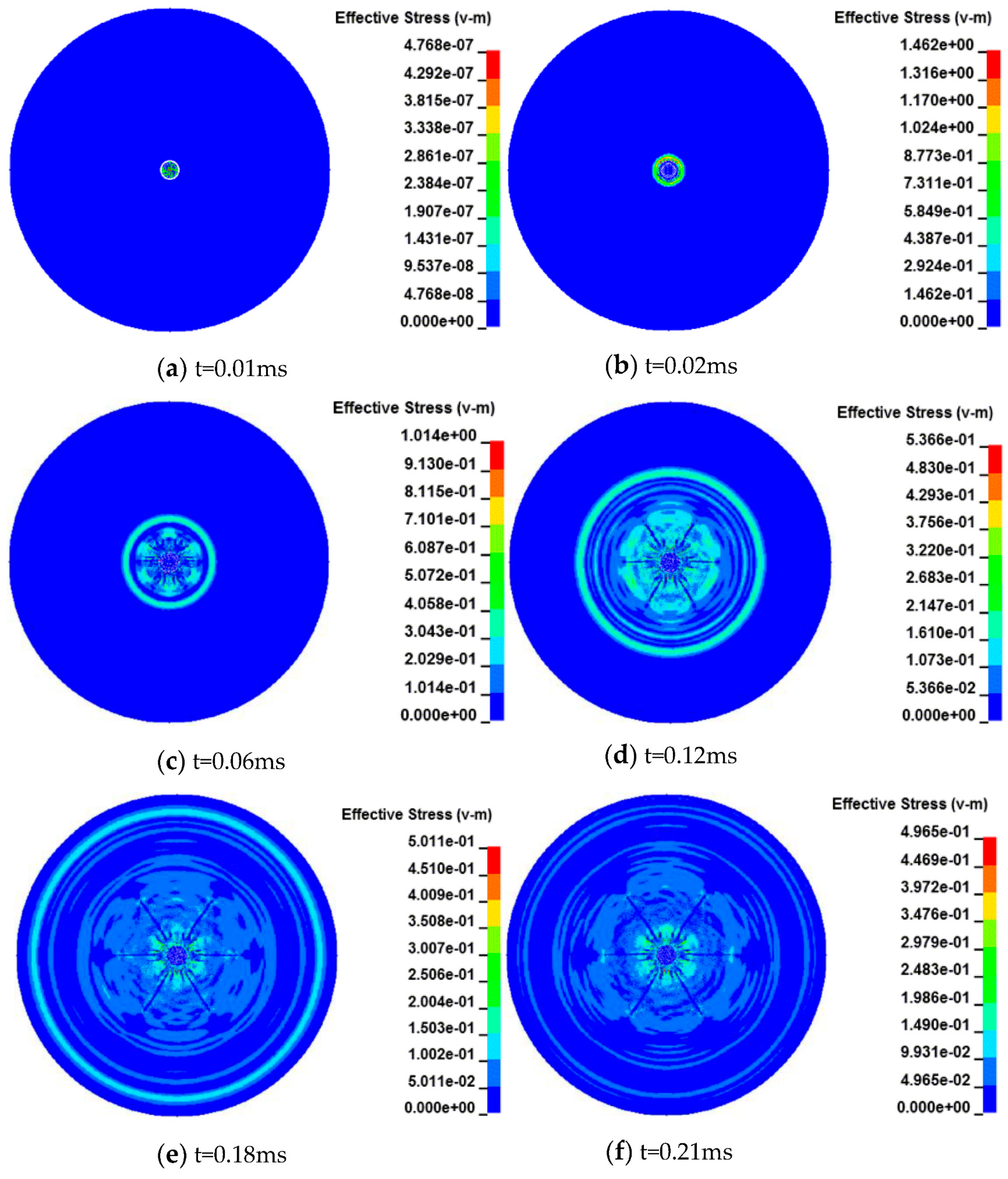
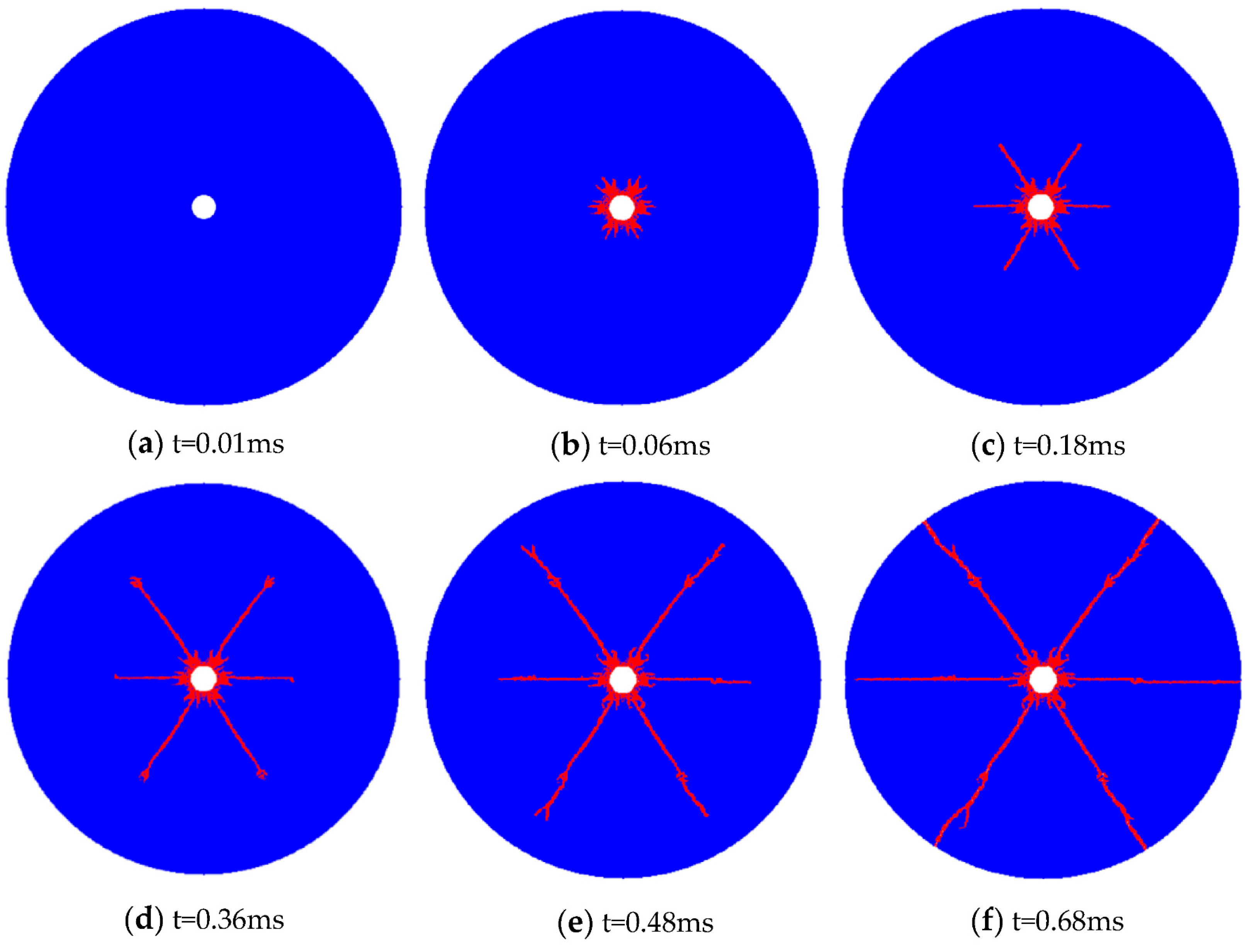
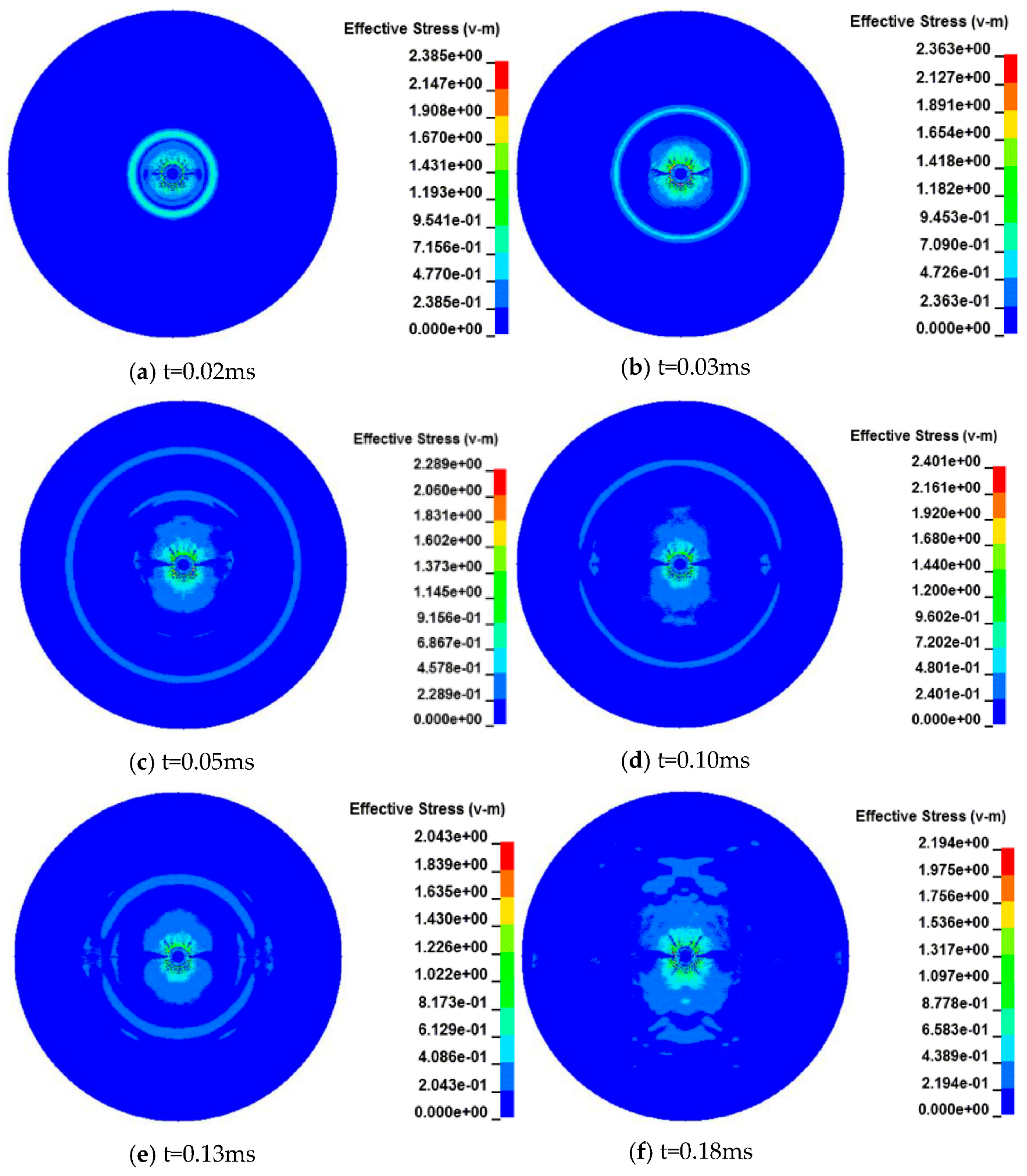
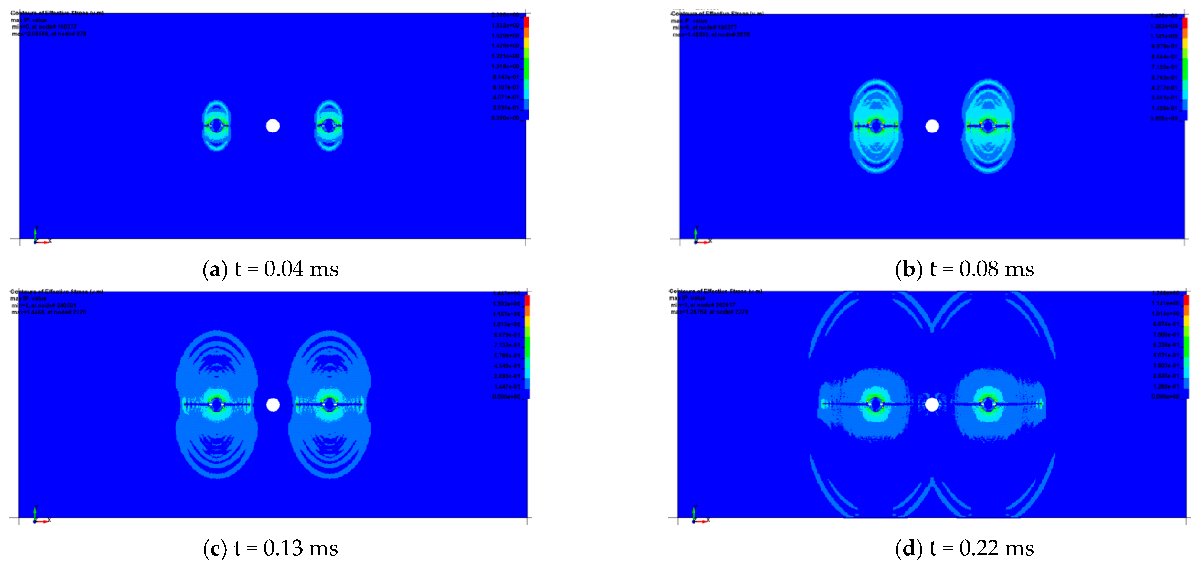
The stress evolution process of non-shaped blasting is shown in Figure 18, and the development process of detonation cracks during non-shaped blasting is shown in Figure 19. After the detonation of the explosive, a strong explosive stress wave is produced. The explosive stress wave reaches the blasting hole wall to form obvious compressive shear stress. With the superposition of the explosive gas stress, the concentration degree of the compressive shear stress in the surrounding rock near the blasting hole wall becomes higher and higher. When the compressive stress exceeds the compressive shear strength of the surrounding rock, massive blasting cracks are generated in the surrounding rock near the hole wall, forming the compressive shear failure zone around the blast hole. After that, the explosive stress wave forms a tensile stress concentration zone along six directions in the surrounding rock. Under the action of tension stress, the surrounding rock evenly cracks along the six directions at a 60° equal angle to form six tensile cracks, and tensile stress concentration occurs at the crack tip. With the continuous propagation of the explosive gas stress, the crack tip is constantly broken and opened under the effect of tensile stress, resulting in the crack extending along six directions until it runs through. It can be seen that in the case of non-shaped charge blasting, the cracks do not develop along the horizontal ideal shaped charge direction, and the surrounding rock appears to be broken as a whole under the action of the detonation stress wave, which means that the blasting effect is poor. In addition, due to the large number of crack groups, a large amount of explosive energy is consumed.
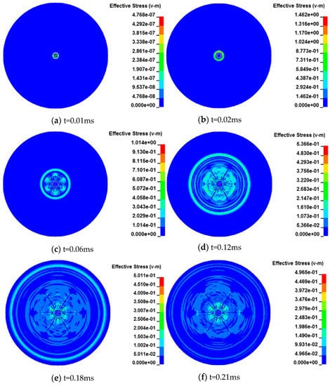
Figure 18.
Stress evolution process of single-hole non-shaped charge blasting.
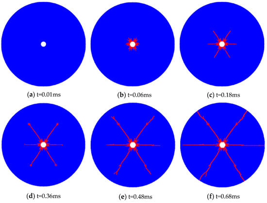
Figure 19.
Development process of cracks caused by single-hole non-shaped charge blasting.
(2) Detonation stress and crack analysis of single-hole shaped charge blasting
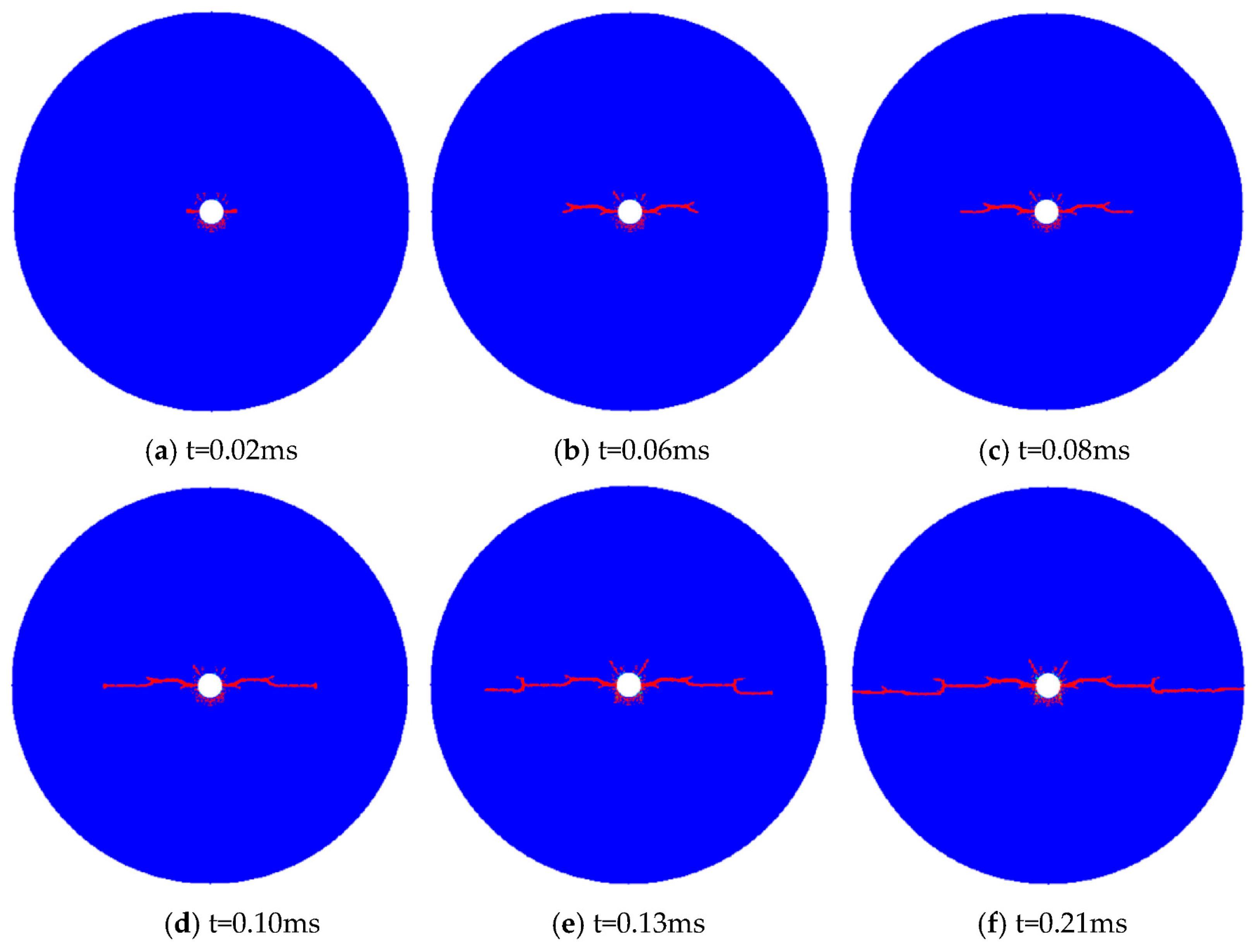
The stress evolution process of single-hole shaped charge blasting is shown in Figure 20, and the development process of explosive cracks during single-hole shaped charge blasting is shown in Figure 21. The instant after the explosive is detonated, a tensile stress concentration zone appears near the shaped charge hole, and the rock nearby bears the effect of the tensile stress. When the tensile stress exceeds the tensile strength of the surrounding rock, tensile cracks are generated in the surrounding rock near the shaped hole. When the initial tensile crack forms, the surrounding rock cracks along the horizontal single-shaped direction to form two tensile cracks under the action of tensile stress, and the tensile stress concentration occurs at the crack tip. With the continuous propagation of the explosive stress wave, the crack tip is constantly broken and opened under the effect of tensile stress, resulting in the crack extending along the shaped direction until it runs through. It can be seen that in the case of shaped charge blasting, the cracks develop and spread through along the horizontal ideal shaped charge direction, and there is no overall fracturing of the surrounding rock under the action of the detonation stress wave; therefore, the shaped charge blasting effect is good. At the same time, because only a group of cracks are generated and very little explosive energy is consumed, the tertiary coal mine emulsion explosive can fully meet the requirements of shaped charge blasting.
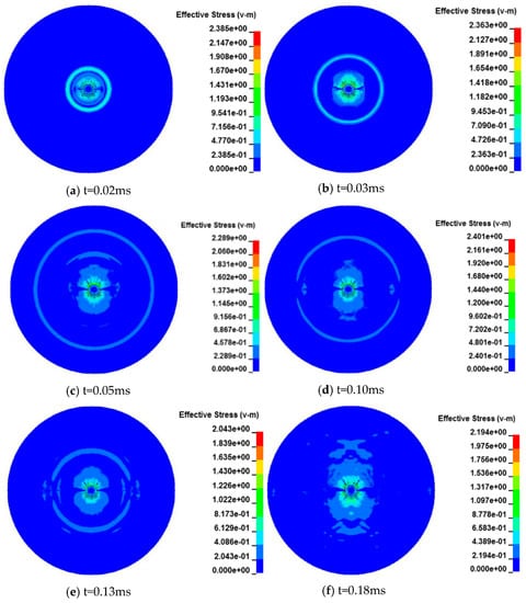
Figure 20.
Stress evolution process of single-hole shaped charge blasting.
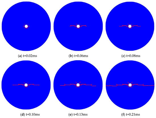
Figure 21.
Development process of crack initiation by single-hole shaped charge blasting.
- (2)
- Numerical simulation of multi-hole cumulative blasting
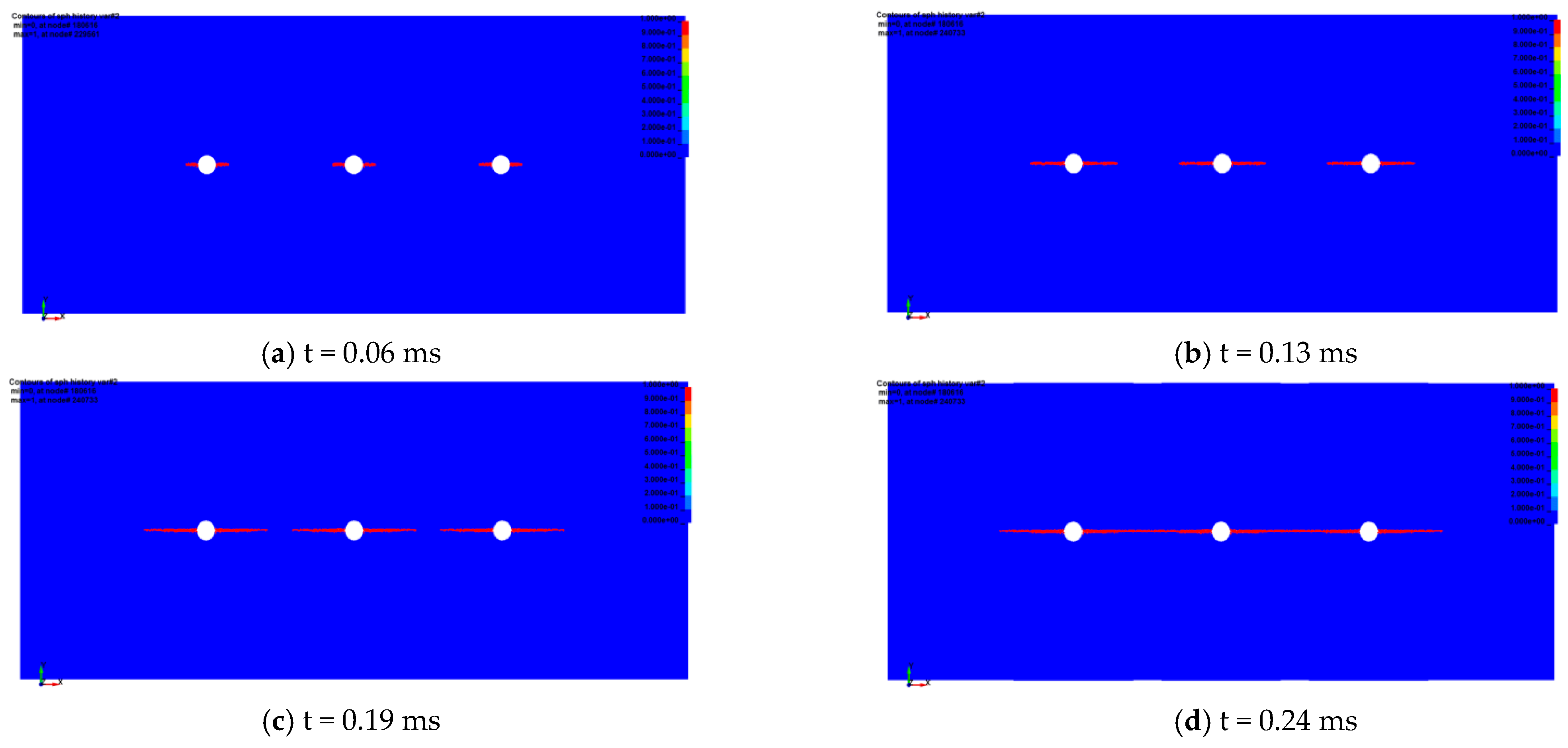
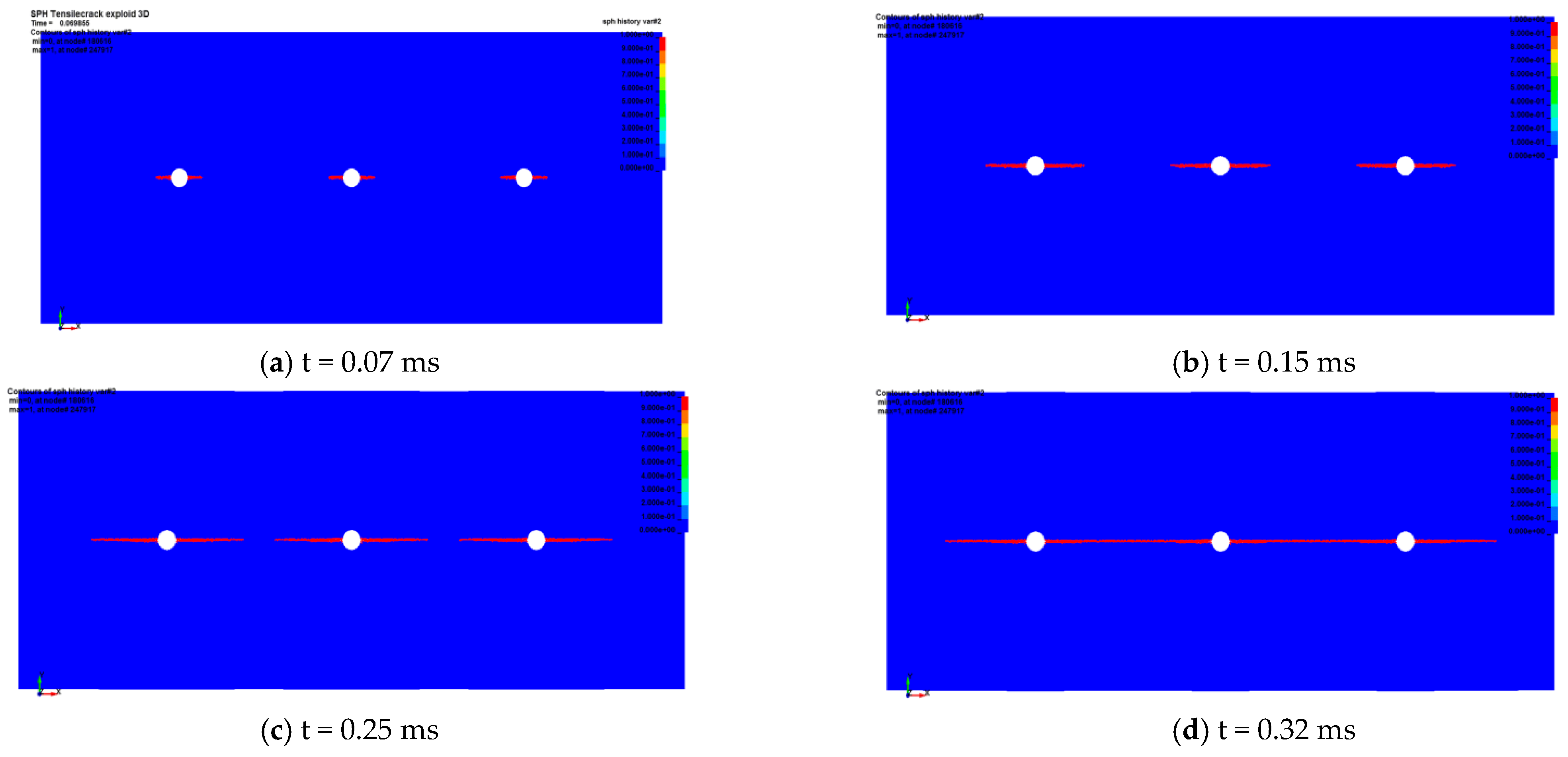
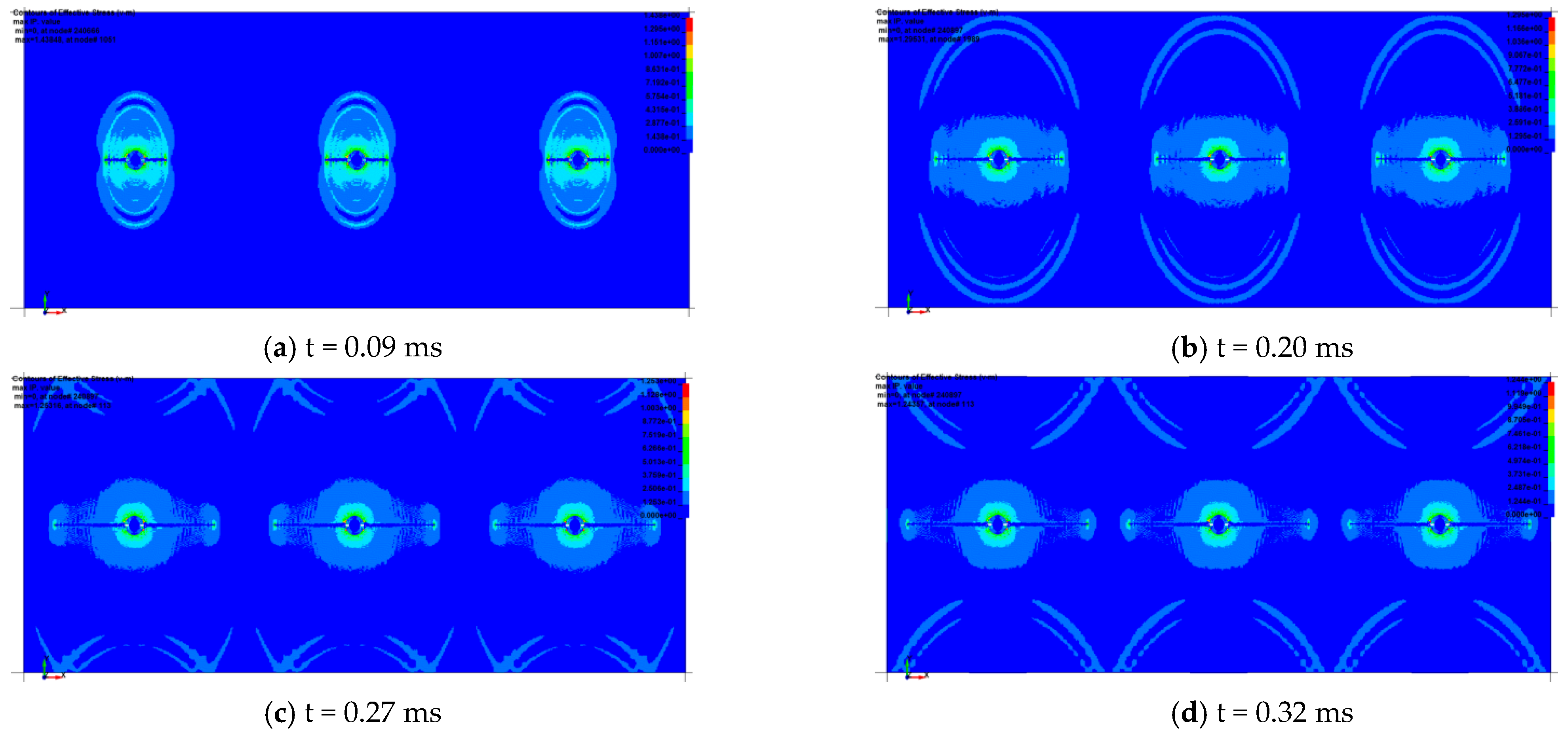
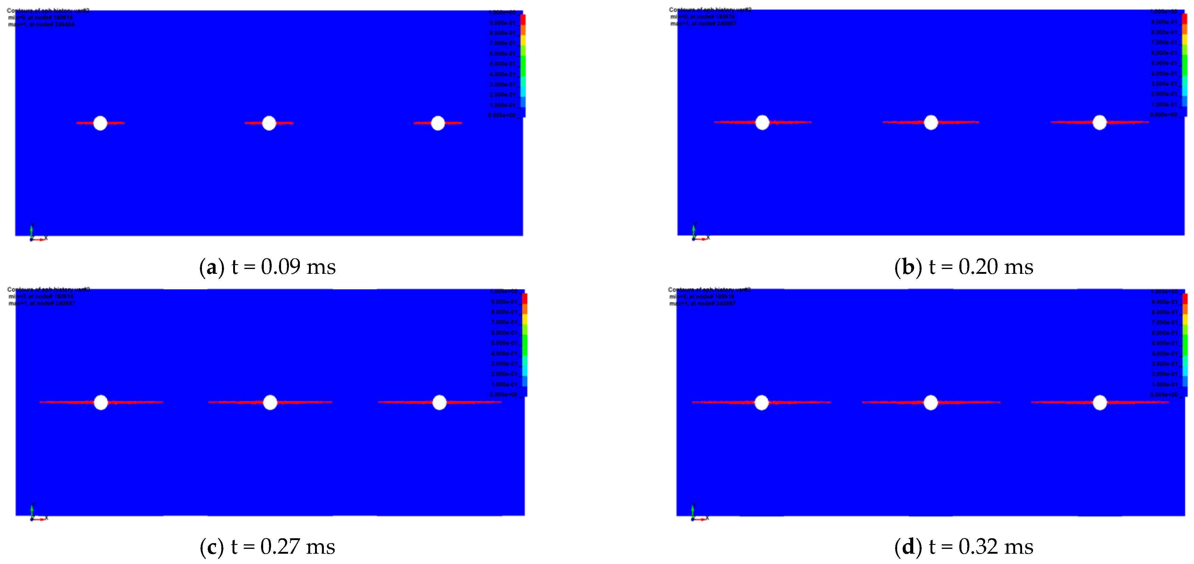
By comparing and analyzing the stress evolution law and the development law of blasting cracks under a 400 mm, 500 mm, and 600 mm hole spacing, the optimal hole spacing of shaped charge blasting was obtained.
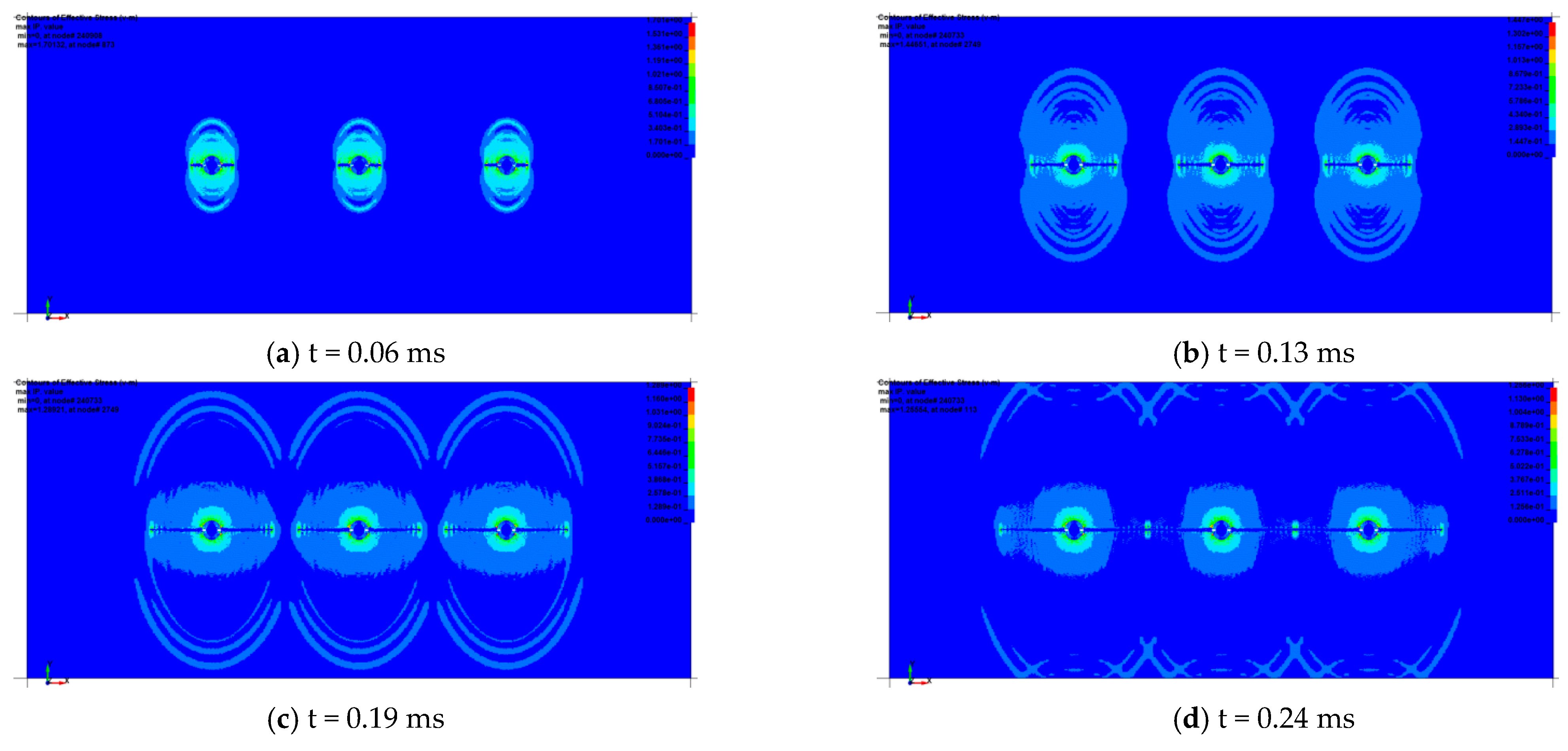
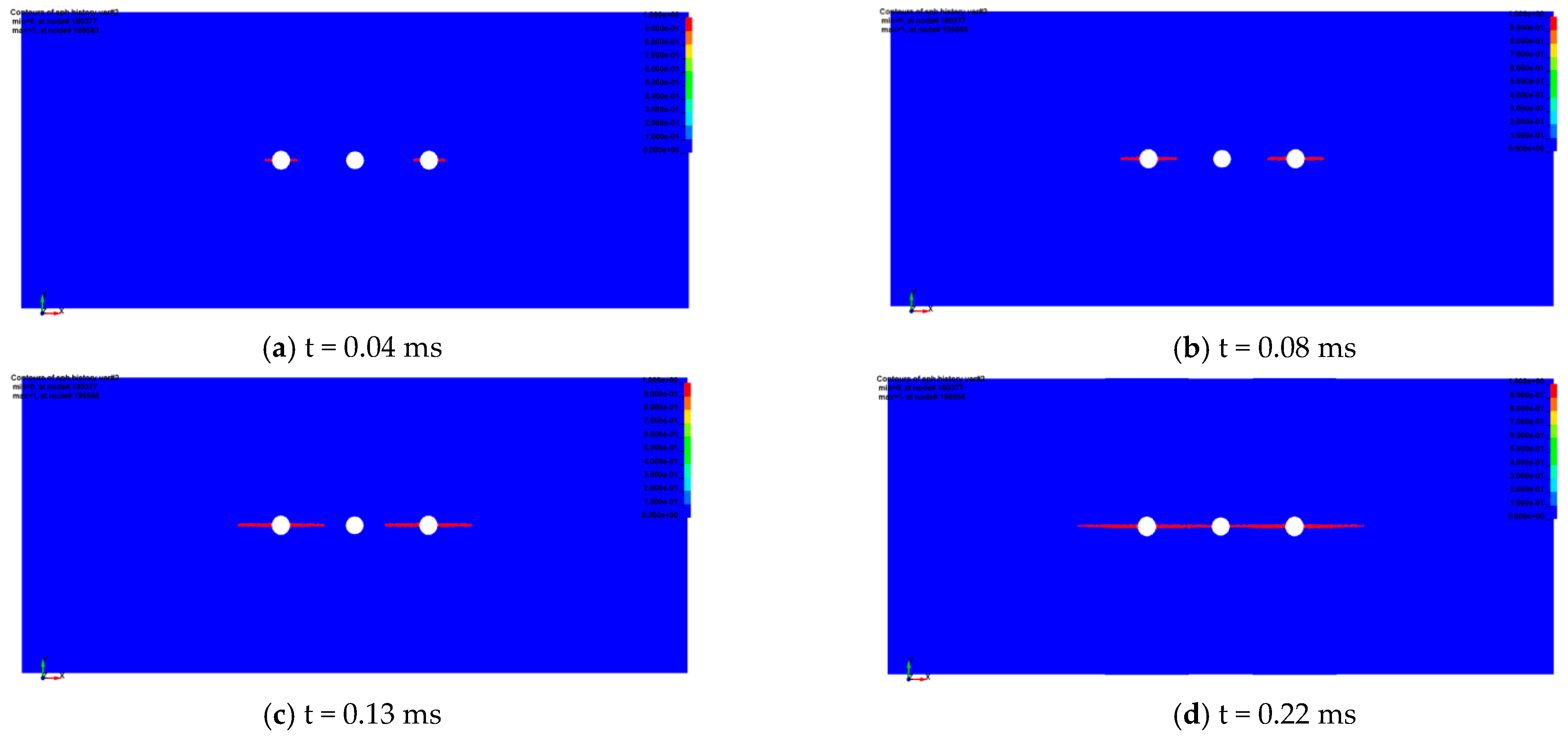
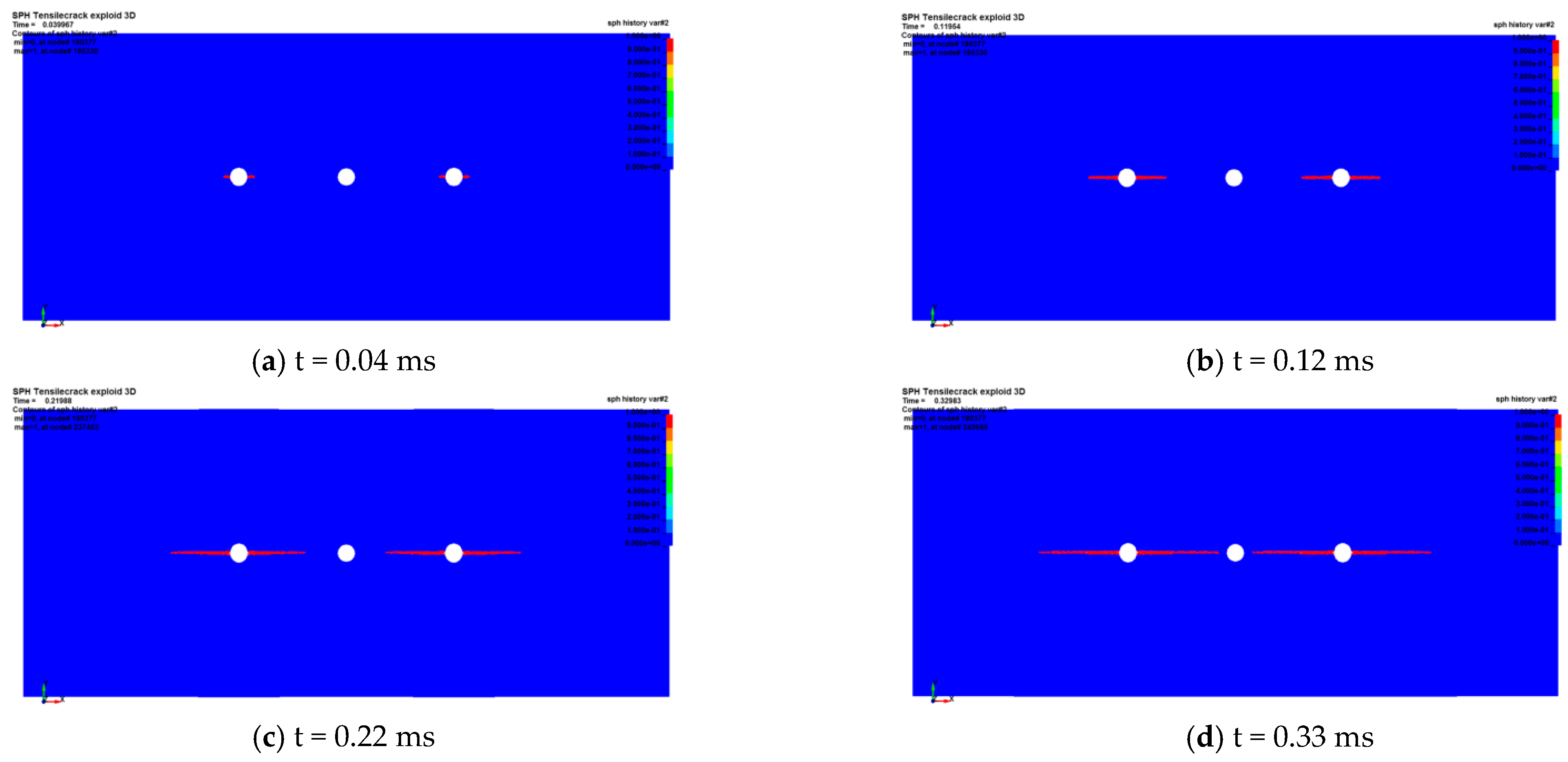
The stress evolution process of multi-hole shaped charge blasting and the development process of blasting cracks are shown in Figure 22, Figure 23, Figure 24, Figure 25, Figure 26 and Figure 27. The instant after the explosive is detonated, a tensile stress concentration zone appears near all shaped charge holes, and the rocks nearby bear the effect of the tensile stress. When the tensile stress exceeds the tensile strength of the surrounding rock, a tensile crack is generated in the surrounding rock near the shaped hole. When the initial tensile crack forms, the surrounding rock cracks along the horizontal single-shaped direction to form six tensile cracks under the action of tensile stress, and the tensile stress concentration is observed at the crack tip perpendicular to the crack surface. With the continuous propagation of the explosive stress wave, the tensile stress zone of the crack tip also moves forward, and the crack tip is constantly destroyed and opened under the effect of the tensile stress, resulting in the continuous propagation of the crack along the direction of the shaped energy. When the spacing between the holes is 400 mm and 500 mm, the tension crack propagates through the adjacent holes. However, when the spacing between the holes is 600 mm, the tension crack generated by the adjacent holes fails to propagate through; then, the adjacent empty holes stop developing and expanding. The reason is that the strength of the explosive stress wave decreases continuously during the propagation process, which affects the tension stress generated by it. When the tensile stress is lower than the tensile strength of the surrounding rock, the tensile cracks will stop growing and expanding. It can be seen that in the case of multi-hole shaped charge blasting, when the hole spacing is 400 mm and 500 mm, the cracks develop and expand along the horizontal ideal shaped charge direction and connect with each other, and a fully connected tension crack is formed between the adjacent holes. Multi-hole shaped charge blasting has a good effect. Considering the cost effectiveness of perforation construction and blasting, the optimal hole spacing is 500 mm.
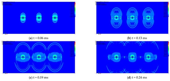
Figure 22.
Stress evolution process of 400 mm spacing multi-hole shaped charge blasting.
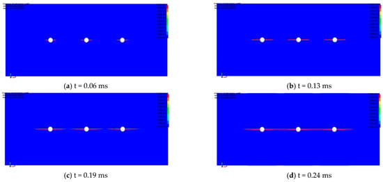
Figure 23.
Development process of cracks caused by multi-hole blasting with 400 mm spacing.


Figure 24.
Stress evolution process of 500 mm spacing multi-hole shaped charge blasting.
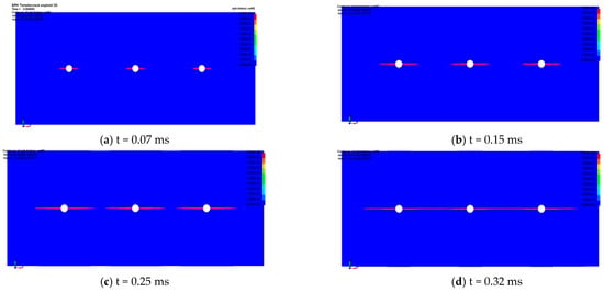
Figure 25.
Development process of cracks caused by multi-hole blasting with 500 mm spacing.
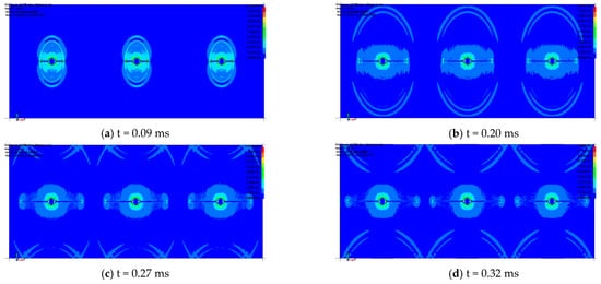
Figure 26.
Stress evolution process of 600 mm spacing multi-hole shaped charge blasting.
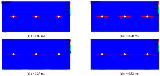
Figure 27.
Development process of cracks caused by multi-hole blasting with 600 mm spacing.
- (3)
- Numerical simulation of spaced-hole cumulative blasting
By comparing and analyzing the stress evolution law and the development law of blasting cracks under a 200 mm and 300 mm hole spacing, the optimal blasting initiation method of cumulative blasting was obtained.
The stress evolution process of spaced-hole shaped charge blasting and the development process of blasting cracks are shown in Figure 28, Figure 29, Figure 30 and Figure 31. The instant after the explosive is detonated, a tensile stress concentration zone appears near all shaped charge holes, and the rocks nearby bear the effect of the tensile stress. When the tensile stress exceeds the tensile strength of the surrounding rock, a tensile crack is generated in the surrounding rock near the shaped hole. When the initial tensile crack forms, the surrounding rock cracks along the horizontal single-shaped direction to form four tensile cracks under the action of the tensile stress, and the tensile stress concentration is observed at the crack tip perpendicular to the crack surface. With the continuous propagation of the explosive stress wave, the tensile stress zone at the crack tip also moves forward. The crack tip is constantly destroyed and opened under the effect of the tensile stress, resulting in the continuous expansion of the crack along the direction of the shaped energy. When the hole spacing is 200 mm, the tension crack propagates through the adjacent empty holes. When the hole spacing is 300 mm, the tension crack generated by the adjacent holes fails to propagate through; then, the adjacent empty holes stop developing and expanding. The reason is that the strength of the explosive stress wave decreases continuously during the propagation process, which affects the tension stress generated by it, and when the tensile stress is lower than the tensile strength of the surrounding rock, the tensile crack stops developing and spreading. It can be seen that in the case of spaced-hole shaped charge blasting, when the hole spacing is 200 mm, the cracks develop and expand along the horizontal ideal shaped charge direction and run through the adjacent empty holes. A fully connected tension crack is formed between the blasting hole and the empty holes. The effect of spaced-hole shaped charge blasting is good, but a large number of empty holes need to be constructed, which greatly affects the cost effectiveness of the hole construction and blasting. At the same time, the setting of empty blast holes does not play an optimal role in promoting the surrounding rock stress evolution and crack development of shaped charge blasting. Therefore, the optimal blasting method is the multi-hole shaped charge blasting with a hole spacing of 500 mm.
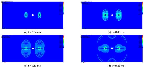
Figure 28.
Stress evolution process of spaced-hole blasting with 200 mm spacing.
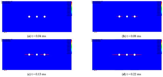
Figure 29.
Development process of cracks caused by spaced-hole blasting with 200 mm spacing.


Figure 30.
Stress evolution process of spaced-hole blasting with 300 mm spacing.
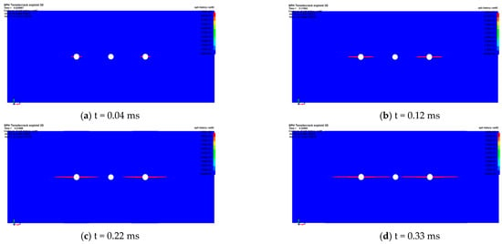
Figure 31.
Development process of cracks caused by spaced-hole blasting with 300 mm spacing.
With the help of LS-DYNA numerical simulation software (version LS-DYNA R11.1.0), taking the geological conditions of the 1,010,201 working face in the Yuwang No.1 Coal Mine as the engineering example, a numerical model was established; then, the blast hole spacing of 400 mm, 500 mm, 600 mm, and two blasting modes of multi-hole cumulative blasting and spaced-hole cumulative blasting were simulated and analyzed, respectively. Numerical simulation software was used to analyze and compare the stress evolution process of shaped charge blasting and the crack development process of shaped charge blasting under different blast spacings and different blasting modes. Considering the engineering quantity and the consumption of labor and materials, the best blast hole spacing is 500 mm, and the best blasting method is multi-hole blasting. In the subsequent actual roof-cutting operation, the blast spacing design should be verified on the basis of this result, and the number of holes for one initiation should be further determined.
4. Special Design for Gas Prevention and Control
The Yuwang No.1 Coal Mine is a typical coal and gas outburst mine in Southwest China; in addition to the design of the key parameters for the conventional 110 mining method of roof cutting mentioned above, the application planning of the 110 mining method also requires a special adaptive technical design for gas prevention and control. This includes (1) the development of a goaf closure system under Y-ventilation conditions with the 110 mining method and (2) research on gas extraction technology based on the 110 mining method.
4.1. Closure Design of the Goaf
After the 110 mining method of roof cutting and roadway retaining in the coal mining face, it takes a certain amount of time to compact the gangue wall of retained entry, and as the working face advances, there is a narrow wind leakage zone beside the lane at a certain distance behind. For the mining of high gas and the protruding coal seam, if the gangue wall formed by roof cutting is not closed in time, not only will the high concentration of gas from the mining area gush into the lane, causing the gas to exceed the limit, but also the coal seam with a risk of natural fire becomes prone to spontaneous combustion with the coal left in the mining area, which may even lead to fire or gas explosion at the working face. Therefore, it is necessary to study a technical solution for a rapid closure system adapted to the shape of the roadway to manage the air leakage of gangue wall formed by roof cutting and to eliminate the above hazards. Based on the application of the 110 mining method in the Yuwang No.1 Coal Mine, the following three types of goaf closure solutions are proposed, and scheme comparison and selection will be carried out at a later appropriate time.
- (1)
- Windpipe cloth + slurry spraying closure program
This is a common way of gangue wall closure under the 110 mining method. Namely, using metal mesh to hang windpipe cloth (a kind of flexible sealing material commonly used in Chinese coal mines, which is usually used for local ventilation and sealing of tunnels) and spraying slurry are used to realize gangue wall closure. This solution has been successfully applied in a number of mines, such as the Ningtiaota Coal Mine and the Faer Coal Mine, but there is the problem that it is difficult to firmly bond the sprayed slurry layer to the windpipe cloth, and it is prone to delamination and cracking after compression and deformation later, which is costly and complicated to repair.
- (2)
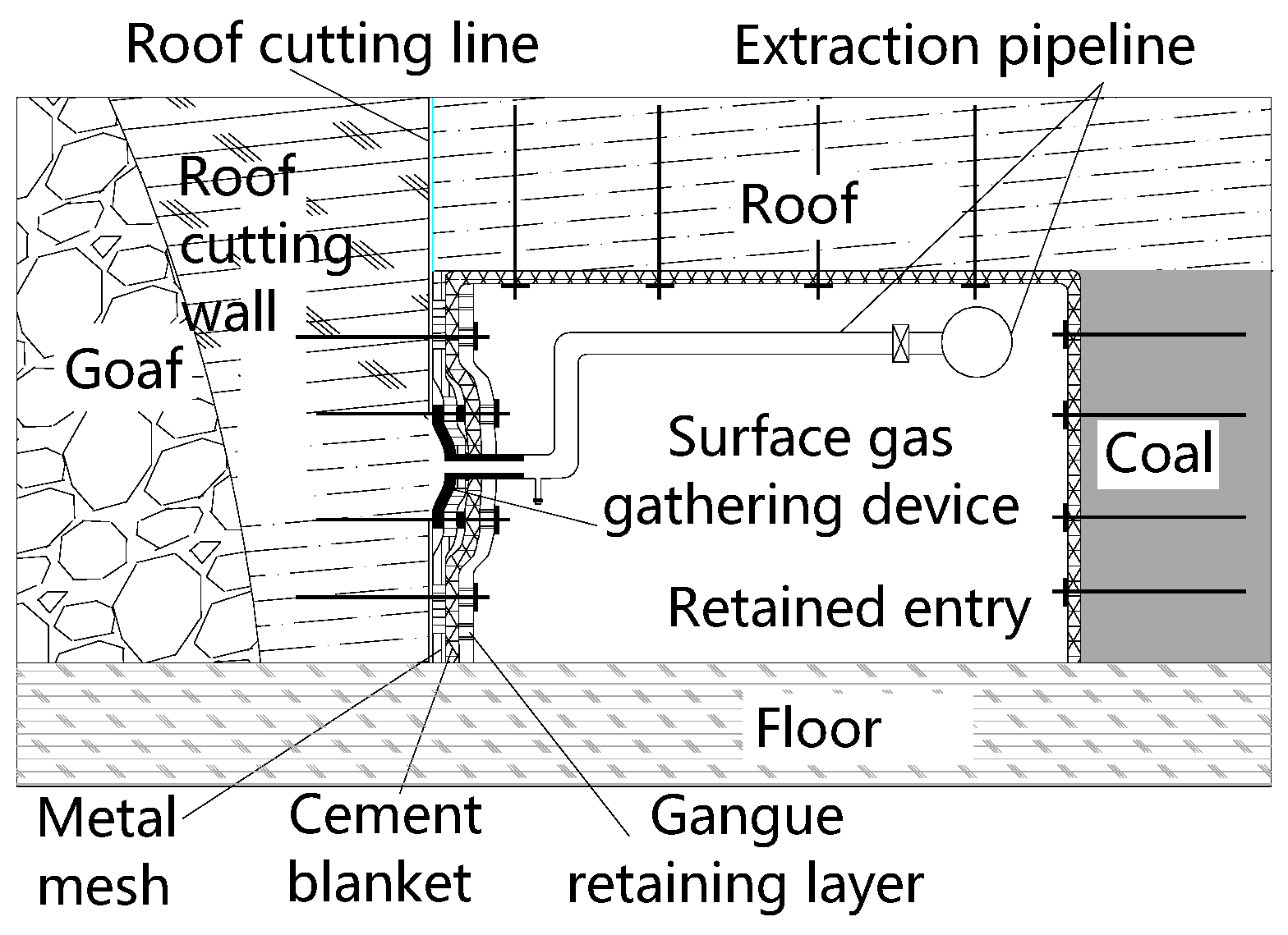
- Cement blanket + local slurry spraying reinforcement closure program (shown in Figure 32)
This solution is an improvement of the abovementioned Solution (1); that is, the windpipe cloth in Solution (1) is replaced by a cement blanket. The inner layer of the cement blanket is geotextile fabric, which can seal the air and water, and the outer layer is mesh and cement. After laying, water is poured and hardened to form a sealing layer. This solution can eliminate the process of large-area slurry spraying, with higher efficiency and a lower cost. The local damage area in the later stage of lane reservation can also be reinforced by guniting. As the cement blanket is mainly made of cement, it has good adhesion with guniting and has a better integrity than the conventional air duct cloth and does not easily delaminate.
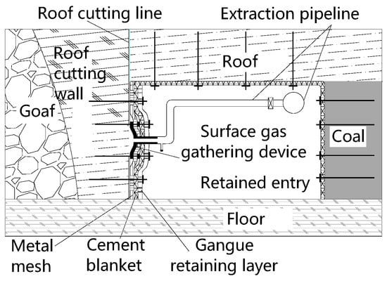
Figure 32.
Schematic diagram of the cement blanket closure and areal gas-gathering device program.
Figure 32.
Schematic diagram of the cement blanket closure and areal gas-gathering device program.
- (3)
- Masonry closure wall closure program (shown in Figure 33)
This solution is to use high-water materials or loess filling bags combined with a sealing wall to close the gangue wall. The main body of the sealing wall is made of brick masonry or is poured with a flexible mold wall; the upper part is filled with loess or a high-water material to close the gap between the wall and the roof. In addition, the loess or high-water material can also offset a certain amount of roof deformation so that the wall is not easy to crush and can enhance the sealing effect.

Figure 33.
Schematic diagram of the masonry closure wall closure program.
Figure 33.
Schematic diagram of the masonry closure wall closure program.

4.2. Design of Goaf Gas Extraction
In addition to the closure of the goaf, gas drainage in the goaf should also be designed adaptively to avoid gas accumulation caused by the roof collapse of the goaf, the escape of residual coal gas, or the inflow of gas from adjacent layers. In this study, two types of gas extraction solutions are proposed for the coal and gas prominence and coal seam group conditions in the Eastern Yunnan Mine Area, which will be selected for implementation in the field, and specific extraction parameters, such as the drilling layout, drilling spacing, and extraction flow rate, will be determined.
- (1)
- Buried pipe method of extraction of gas from the goaf
If wall sealing is used to close the goaf after roof cutting and mining, a gas extraction pipe can be laid along the upper gang of the track lane of the back mining face, a gas pipeline can be placed at a certain distance to set a tee, and a valve can open and close it. As the working face advances, the extraction sieve pipe is connected at the tee along the inner side of the retained entry and is buried into the goaf through the lane wall. When the working face advances to the next buried pipe orifice tee, the extraction sieve tube is buried into the goaf and the valve of the buried pipe orifice is opened. The opening and closing of the control valve of the drainage pipeline inside the retained entry is determined according to the drainage effect of the preceding drainage pipe so as to achieve the goal of continuous gas drainage in the goaf using buried pipes.
- (2)
- Gas collection device to extract gas from the goaf
In general, there is no closed wall outside the gangue wall under the 110 mining method, so it is difficult to embed the pipeline into the lane wall for conventional pipe-laying drainage. Therefore, a plan is proposed to set a surface gas-gathering device on the gangue wall of the roof-cutting retained entry for gas extraction. After the goaf is sealed with airduct cloth or a cement blanket, a gas-gathering device is installed on the closed roadway wall to use the cracks on the gangue wall to extract gas from the goaf, as shown in Figure 32.
4.3. Field Effect Investigation Plan
The purpose of the goaf closure measures under roof-cutting entry retaining is to reduce the amount of air leakage from the working face to the goaf; therefore, when implemented on site, the closure effect can be investigated through the measurement of the air volume at the working face and the retained entry. The unit method is used to determine the airflow at the working face and retained entry. At the same time, the gas concentration at the measurement location is also determined in order to grasp the condition of the gas gushing source at the working face so as to find the specific location of the source of the air leakage between the workface and the goaf and to grasp the law of gas transport and the gas concentration distribution at the working face with the 110 mining method.
The effect of goaf closure and gas extraction under the 110 mining method Y-ventilation can be investigated by measuring the gas concentration in the return airstream of the roof-cutting lane without gas extraction and after the implementation of extraction measures as well as by monitoring parameters, such as the volume fraction and extraction volume in the buried pipe extraction and roof extraction borehole systems. With the continuous advancement of the working face, the roof cutting and roadway retaining enter the stable roadway formation stage. According to the gas emission volume and the emission law of the working face, measured by the unit method, the gas unit method is remeasured after the implementation of the roof high-level drilling and the buried pipe drainage of goaf gas, which can compare whether the gas concentration in the return airflow has a downward trend. The data on the gas volume fraction and drainage flow in the buried pipe drainage pipeline and roof drilling hole are collected uninterruptedly, and the gas in both pipelines is extracted for CO and O2 detection. If the volume fraction of CO gas in the extraction pipeline increases significantly with the working face advancing, the extraction pipeline shall be timely closed according to the distance from the mining line.
Through the above investigation, analysis, and summary of various 110 mining method gas control technologies, it can be concluded that the comprehensive gas control technology model and optimization process is suitable for the conditions of the 110 mining method of roof cutting and roadway retaining in the mining face of the multi-coal seam outburst mine in the Eastern Yunnan Mining area, forming an effective gas control technology system for the mining face in the Eastern Yunnan Mining Area under these conditions.
5. Conclusions and Follow-Up Plan
5.1. Conclusions
- (1)
- This study analyzed the geological conditions of the Yuwang No.1 Coal Mine in the Huaneng Eastern Yunnan Mining Area, summarized the geological characteristics of the 110 mining method test working face, and analyzed the practice feasibility of the 110 mining method according to the geological characteristics of “one soft, one low, two high, and two complex”;
- (2)
- Based on engineering experience, calculations, and analyses, the key parameters of roof cutting in the test working face of the Yuwang No.1 Coal Mine were designed. With the help of numerical simulations, the roof-cutting height, roof-cutting angle, and blasting parameters were numerically simulated and analyzed. The key parameters of roof cutting in the test working face were obtained as follows: the depth of roof cutting is 7 m, the angle of roof cutting is 15°, and the blasting method is multi-hole blasting with a spacing of 500 mm;
- (3)
- In view of the coal and gas outburst and the occurrence conditions of coal seams in the Yuwang No.1 Coal Mine, a variety of goaf closure design schemes and goaf gas drainage design schemes were proposed, and the on-site effect inspection scheme was given.
5.2. Follow-Up Plan
After the first mining face of the Yuwang No.1 Coal Mine is ready, the pilot mine will further carry out the field blasting test and the 110 mining method roadway-retaining test under the guidance of the research results in this paper to verify the rationality of the roof-cutting parameter design and the feasibility of the gangue wall sealing and gas drainage design. Furthermore, in the field practice process, the mining ground pressure law and the adjacent layer gas drainage technology under the condition of the 110 mining method will be continuously studied, and finally, the application technology system of the 110 mining method in the Eastern Yunnan Mining Area will be formed.
Author Contributions
Methodology, X.M., B.H. and D.W.; Investigation, X.M.; Resources, M.H. and C.C.; Data curation, J.L. and J.G.; Writing—original draft, Q.J.; Funding acquisition, Z.B. All authors have read and agreed to the published version of the manuscript.
Funding
This research received no external funding.
Data Availability Statement
The data used to support the findings of this study are included within the article.
Acknowledgments
This research was financially supported by the State Key Laboratory for Geomechanics and Deep Underground Engineering (SKLGDUEK2020), Huaneng Group headquarters science and technology project (HNKJ21-H07/HNKJ21-H56-10) and the Coal Burst Research Center of China Jiangsu. In addition, my nephew Gao Qi was born on 14 January 2023, and I am thankful for his arrival.
Conflicts of Interest
The authors declare no conflict of interest.
References
- Kang, H.P.; Niu, D.L.; Zhang, Z.; Lin, J.; Li, Z.H.; Fan, M.J. Deformation Characteristics of Surrounding Rock and Supporting Technology of Gob-side Entry Retaining in Deep Coal Mine. Chin. J. Rock Mech. Eng. 2010, 29, 1977–1987. [Google Scholar]
- Gao, X.; Liu, S.; Zhao, C.; Yin, J.; Fan, K. Damage Evolution Characteristics of Back-Filling Concrete in Gob-Side Entry Retaining Subjected to Cyclical Loading. Minerals 2022, 15, 5772. [Google Scholar] [CrossRef]
- Xue, Y. From Tradition to Modern Times: Evolution of Coal Mining Technology in China. J. HuBei Polytech. Univ. (Humanit. Soc. Sci.) 2013, 30, 7–15. [Google Scholar]
- He, M.; Song, Z.; Wang, A.; Yang, H.; Qi, H.; Guo, Z. Theory of longwall mining by using roof cuting shortwall team and 110 method—The third mining science and technology reform. Coal Sci. Technol. Mag. 2017, 1, 1–9+13. [Google Scholar]
- Ghabraie, B.; Ren, G.; Smith, J.; Holden, L. Application of 3D laser scanner, optical transducers and digital image processing techniques in physical modelling of mining-related strata movement. Int. J. Rock Mech. Min. Sci. 2015, 80, 219–230. [Google Scholar] [CrossRef]
- Hu, J.; Braytsev, U. Coal Seam Coal-Free Column Mining; Cui, M., Translator; China University of Mining and Technology Press: Beijing, China, 1991. [Google Scholar]
- Shi, J.; Ma, N.; Bai, Z. Analysis on Roof Broken Location of Gateway Retained along Goaf and Technology of Roof Support. Coal Sci. Technol. 2013, 41, 35–37+42. [Google Scholar]
- Li, Y.; Hua, X. Mechanical analysis of stability of key blocks of overlying strata for gob-side entry retaining and calculating width of roadside backfill. Rock Soil Mech. 2012, 33, 1134–1140. [Google Scholar]
- Ajayi, S.A.; Ma, L.; Spearing, A.J. Spearing. Ground Stress Analysis and Automation of Workface in Continuous Mining Continuous Backfill Operation. Minerals 2022, 12, 754. [Google Scholar] [CrossRef]
- He, M.C.; Xie, H.P.; Peng, S.P.; Jiang, Y.D. Study on Rock Mechanics in Deep Mining Engineering. Chin. J. Rock Mech. Eng. 2005, 24, 2803–2813. [Google Scholar]
- He, M.C.; Ma, X.G.; Niu, F.L.; Wang, J.; Liu, Y.X. Adaptability research and application of rapid gob-side entry retaining formed by roof cutting and pressure releasing with composite roof and medium thick coal seam. Chin. J. Rock Mech. Eng. 2018, 37, 2425–2434. [Google Scholar]
- He, M.; Ma, X.; Yu, B. Analysis of Strata Behavior Process Characteristics of Gob-Side Entry Retaining with Roof Cutting and Pressure Releasing Based on Composite Roof Structure. Shock Vib. 2019, 2019, 2380342. [Google Scholar] [CrossRef]
- Ma, X.; He, M.; Sun, J.; Wang, H.; Liu, X.; Zhen, E. Neural Network of Roof Cutting Blasting Parameters Based on Mines with Different Roof Conditions. Energies 2018, 11, 3468. [Google Scholar] [CrossRef]
- Sun, X.M.; Liu, X.; Liang, G.F.; Wang, D.; Jiang, Y.L. Key Parameters of Gob-Side Entry Retaining Formed by Roof Cut and Pressure Releasing in Thin Coal Seams. Chin. J. Rock Mech. Eng. 2014, 33, 1449–1456. [Google Scholar]
- Guo, Z.B.; Wang, J.; Cao, T.P.; Chen, L.; Wang, J. Research on key parameters of gob-side entry retaining automatically formed by roof cutting and pressure release in thin coal seam mining. J. China Univ. Min. Technol. 2016, 45, 879–885. [Google Scholar]
- Ma, X. Research on Key Technologies and Rock Pressure Law of 110 Mining Method with Compound Hard Roof in Tashan Coal Mine; China University of Mining and Technology: Beijing, China, 2019. [Google Scholar]
- China Huaneng Group Co. China Huaneng Group Co., Ltd.’s “14th Five-Year” Development Plan; China Huaneng Group Co.: Beijing, China, 2022. [Google Scholar]
- Huaneng Coal Co. Coal Industry “14th Five-Year” Scientific and Technological Innovation Plan; China Huaneng Group Co., Ltd.: Beijing, China, 2022. [Google Scholar]
- Zhao, R. Comprehensive Detection of Hydrogeological Conditions and Design of Water Prevention in Panel 101 of the Yuwang Coal Mine No.1 in Yunnan Province; China University of Mining and Technology: Beijing, China, 2021. [Google Scholar]
- Gan, X. Hydrogeological condition analysis and prevention countermeasures of No.1 mine field of Yuwang Coal Mine. J. Beijing Polytech. Coll. 2021, 20, 1–4. [Google Scholar]
- Mahoutian, M.; Shekarchi, M.; Libre, N.A. Application of steel fiber reinforced lightweight aggregate concrete in underground mining. J. Min. Sci. 2011, 47, 606–617. [Google Scholar] [CrossRef]
- Ma, X.; He, M.; Li, W.; Wang, Y.; Li, L.; Sun, X.; Li, Y.; Gu, L.; Sha, X. Research and application of open-off cut roof cutting pressure releasing technology. Adv. Civ. Eng. 2021, 5, 9989213. [Google Scholar] [CrossRef]
- Park, S.J.; Kim, G.J.; Kwak, H.G. Characterization of stress-dependent ultrasonic nonlinearity variation in concrete under cyclic loading using nonlinear resonant ultrasonic method. Constr. Build. Mater. 2017, 145, 2172–2282. [Google Scholar] [CrossRef]
- Duchnowski, R.; Wyszkowska, P. Unstable Object Points during Measurements—Deformation Analysis Based on Pseudo Epoch Approach. Sensors 2022, 22, 9030. [Google Scholar] [CrossRef]
- T/CCCA 002-2018; Standard for 110 Law of Self-Made Lane without Coal Columns. China Coal Construction Association: Beijing, China, 2018.
- Fei, H.; Guo, Y. Study on optimized selection for row interval time of staggered sector deep-hole caving method based on LS-DYNA. J. Saf. Sci. Technol. 2022, 18, 127–134. [Google Scholar]
- Breccolotti, M.; Bonfigli, M.F.; D’Alessandro, A.; Materazzi, A.L. Constitutive modeling of plain concrete subjected to cyclic uniaxial compressive loading. Constr. Build. Mater. 2015, 94, 172–180. [Google Scholar] [CrossRef]
- Verma, A.K.; Singh, T.N. Modeling of a jointed rock mass under triaxial conditions. Arab. J. Geosci. 2010, 3, 91–103. [Google Scholar] [CrossRef]
- He, M.; Ma, X.; Wang, J.; Zhang, J.; Liu, Y.X. Feature Analysis of Working Face Strata Pressure with Roof Cutting Pressure Releasing in Medium-thick Seam and Compound Roof Condition. Chin. J. Rock Mech. Eng. 2018, 37, 2641–2654. [Google Scholar]
Disclaimer/Publisher’s Note: The statements, opinions and data contained in all publications are solely those of the individual author(s) and contributor(s) and not of MDPI and/or the editor(s). MDPI and/or the editor(s) disclaim responsibility for any injury to people or property resulting from any ideas, methods, instructions or products referred to in the content. |
© 2023 by the authors. Licensee MDPI, Basel, Switzerland. This article is an open access article distributed under the terms and conditions of the Creative Commons Attribution (CC BY) license (https://creativecommons.org/licenses/by/4.0/).

