1. Introduction
Electrocorrosion of construction from leakage currents from direct current sources, mainly electrified transport, causes significant damage worldwide. The most reliable methods of protection against it are electrochemical, incl. drainage of electrical currents in various ways. These methods involve the use of grounding devices, electrically conductive metal screens, etc. However, metals are expensive, and devices made of them quickly corrode themselves, instead of the structure. It is promising to develop electrically conductive composites based on mineral binders for the development of electrocorrosion protection devices using plastering and painting methods [
1,
2,
3].
Electrically conductive composites based on mineral binders are widely used in modern construction. These composites, incl. concretes, are used for the practice of monitoring deformation changes in structures. The application of these composites as strain sensors is due to a change in the electrical resistivity with strain. In work [
4], concrete with nano-carbon black and carbon fiber, which were added as electrically conductive materials, was researched. The effects of the beam damage degree on the fractional change in resistance were investigated. It was also concluded that the electrically conductive addition used had little effect on the strength of the concrete. In reference [
5], properties of cement composites with the addition of carbon fibers and carbon nanofibers were studied. The possibility of using these composites as strain sensors in elastic sensing condition testing was evaluated. In work [
6], steel fibers were used as electrically conductive elements, and silica fume was used to improve strength and accelerate material dispersion in cement composites. According to the research, silica fume contributes indirectly to conductivity by permitting the dispersion of conductive materials. The effectiveness of the simultaneous use of steel fiber and silica fume was proven in the work—the resistivity of the composite was reduced by 94%. The papers [
7,
8], etc., confirmed the effectiveness of the use of electrically conductive concrete in the heating system of pavements and for bridge deck deicing. In work [
7], steel fibers and shaving were added to the concrete as conductive materials. In reference [
8], the influence of a variety of factors on the electrical and mechanical characteristics of electrically conductive concrete was investigated, while carbon fiber in different size classes was used as an electrically conductive constituent, methyl cellulose was used as a fiber dispersive agent and corrosion inhibitor admixtures were used as conductivity-enhancing agents. It is also known about the use of electrically conductive composites as shielding elements from electromagnetic interference; for example, in [
9], to improve the characteristics of electromagnetic shielding of concrete, graphite powder, carbon black and steel fibers were introduced to its composite. In works [
10,
11], the effectiveness of the use of cement conductive anodes for the application of cathodic protection to control corrosion in reinforced concrete structures was evaluated and proved.
The main components of such electrically conductive composites are mineral binders, aggregates of varying degrees of dispersion, water, electrically conductive additive and chemical admixtures [
12]. Such composites use such mineral binders as Portland cement [
13,
14] or alkaline binders [
15,
16,
17].
Electrically conductive composites based on Portland cement are characterized by poor fluidity [
18], their consumption per 1 m
2 of structure is high and their use for structures with still-intact concrete requires a feasibility study. The creation of a composite with improved fluidity and which could be applied in a thin layer could possibly be based on sodium silicates. An analysis of works [
15,
16,
17,
19,
20] and other studies of alkaline binders suggested the possibility of creating an electrically conductive silicate composite based on water glass—sodium silicate for screen protection of structures that do not require restoration of the bearing capacity and repair of the surface.
2. Theoretical Justifications for the Development of the Composite of the Electrically Conductive Silicate Composite
Silicate composites based on water glass and mineral fillers are used more often for corrosion protection in acidic media [
21]. Usually, acid-resistant fillers—diabase, andesite, etc.—and a hardener—sodium fluorosilicate—are used. Sodium silicates nNa
2O·mSiO
2 interact with sodium fluorosilicate Na
2SiF
6 to form a gel of silicic acid Si(OH)
4, which provides binding properties due to coagulation [
21]:
However, such composites have insufficient water resistance (softening coefficient), no more than 0.2, and it was proposed in [
1,
3,
21] to increase it via the introduction of ground basic blast-furnace granulated slag instead of part or all of sodium fluorosilicate. By analogy with slag–alkali binders [
22,
23], the interaction of its silicate and aluminate minerals and glass with sodium silicate causes the formation of a certain amount of zeolite-like calcium, alkali and alkaline earth aluminosilicates, which provide an increase in water resistance.
Theoretical studies have been carried out to improve the water resistance of silicate composites by introducing ground blast-furnace granulated slag, in particular, thermodynamic calculations [
3]. Based on the negative values of the Gibbs free energy of the reactions, it was concluded that in the case of curing of sodium silicates with sodium fluorosilicate, the products of their interaction are orthosilicic acid gel Si(OH)
4 and sodium fluoride:
According to the research of Professor P. Krivenko [
23], sodium fluoride NaF, when interacting with minerals of blast-furnace slag of the gehlenite type C
2AS, forms zeolite-like calcium-sodium hydroaluminosilicates (hydronepheline NAS
2H
2, calcium hydroaluminate C
3AH
6, C
2AH
8), calcium hydrosilicates C
2S
3H
2.5, C
6S
6H and slightly soluble (0.016 g/L) calcium fluoride CaF.
Thermodynamic calculations were performed to establish the possibility of the formation of hydronepheline NAS
2H
2, calcium hydroaluminate C
3AH
6 and calcium fluoride CaF
2 due to the interaction of slag with sodium fluoride NaF according to the scheme:
For thermodynamic calculations for slag, the conditional compound [2CaO+Al
2O
3+SiO
2] was adopted, for which the value Δ
G = −3808.31 kJ/mol was taken as for C
2AS according to [
24], and for which it is possible to construct stoichiometric equations. The value of the Gibbs free energy Δ
G, the formation of compounds from elements, is taken from the data of [
24].
The results of calculations of the Gibbs free energy of this and other possible reactions of the interaction of this conditional compound with various alkaline components are given in
Table 1.
The model of a dispersed system, which properties determine the surface phenomena and electrical surface properties of the particles of the dispersed phase and the contacts between them, is of great importance for the analysis of stability under operating conditions of composite materials based on mineral binders. Electric surface charges are quantitatively characterized by the electrosurface potential
ψ, V. In [
25,
26,
27], a method for determining the absolute and equilibrium electrosurface potentials of substances using electrochemical and energy calculation and experimental methods was developed. Using this method, the electrical surface potentials of the particles of the formed compounds were determined.
Absolute electrosurface potentials
and equilibrium electrosurface potentials
were calculated using the following:
where
,
, respectively, are the absolute and equilibrium electrosurface potentials of the compound
XxYyZz;
,
and
are the absolute electrosurface potentials of simple substances that make up the compound
XxYyZz (
Table 2). For the pore electrolyte of orthosilicic acid gel Si(OH)
4, the pH value is taken equal to seven.
Absolute electrosurface potentials
and equilibrium electrosurface potentials
of orthosilicic acid gel Si(OH)
4, hydronepheline NAS
2H
2, calcium hydroaluminate C
3AH
6 are equal to, respectively:
The electrosurface potentials of sodium and calcium fluoride (NaF and CaF
2) were calculated in a similar way. The calculation results are summarized in
Table 3.
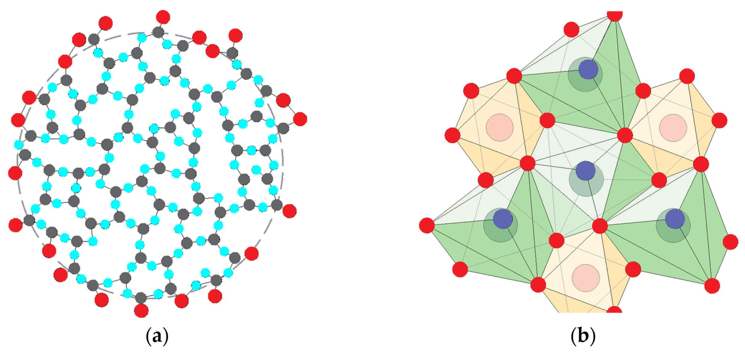
An analysis of the structure of the composites under consideration was carried out, taking into account their electrosurface properties. The main components of this structure are particles of orthosilicic acid gel. According to [
28], gel particles are rounded particles ranging in size from 2–3 to 15 nm, sometimes up to 60 nm. Calcium hydroaluminate C
3AH
6 is usually represented by hexagonal crystals ranging in size from 50 nm to 500 nm,
Figure 1. Fluorite CaF
2 crystals have cubic, octahedral and cuboctahedral shapes, and their sizes under compressed growth conditions are apparently comparable to the sizes of orthosilicic acid gel particles and calcium hydroaluminate C
3AH
6.
The microstructure of an artificial stone of sodium silicate cured with sodium silicon fluoride can be represented by the diagram in
Figure 2a.
Table 3 shows that Si(OH)
4 and NaF particles have a negative surface charge and form only electro-homogeneous contacts with each other (between particles with similarly charged surfaces through electrical double layers,
Figure 2a), which, under dry conditions, due to high concentrations of pore electrolyte NaF, have high strength, but are not water resistant.
Hydronepheline particles also have a negative surface charge, while particles of calcium hydroaluminate C
3AH
6 and calcium fluoride CaF
2 have a positive surface charge. This suggests that the increase in the water resistance of an artificial stone of sodium silicate cured with sodium silicon fluoride, due to the addition of ground blast-furnace granulated slag, is provided not by the formation of zeolite-like hydroaluminosilicates according to [
21], but by the formation of calcium hydroaluminate. In this case, electroheterogeneous contacts are formed between the particles of the gel of orthosilicic acid Si(OH)
4 and calcium hydroaluminate.
Electrically conductive additives are the main components that form the electrical conductivity due to the formation of a continuous network in the composite matrix [
29,
30,
31]. Electrically conductive additives can consist of a single material [
32,
33] or a mixture of different materials with high electrical conductivity [
4,
32]. An analysis of preliminary studies made it possible to identify the additive of finely dispersed graphite as the most effective one [
32,
34]; this additive has a relatively low cost and the best electrical properties (impedance). However, the issues of the interaction of carbon-graphite fillers with a silicate composite based on water glass and the effect on its properties have not been studied.
3. Materials and Methods
For the production of electrically conductive composites, a sodium silicate solution (water glass—Wg) with a silicate modulus of 2.7 was used, the hardener was sodium fluorosilicate Na
2SiF
6 and the superplasticizer additive was sulfonated naphthalene formaldehyde. The combined filler consisted of blast-furnace granulated ground slag (S) from the Mariupol Metallurgical Plant—the chemical composite of slag is given in
Table 4—and an electrically conductive fine graphite powder (G) of the lubricating grade GS-1—the properties are given in
Table 5.
The mix designs were made to determine the effect of the content of the graphite powder additive on the electrical conductivity. In the composition, the graphite content varied from 0 to 4, and the content of liquid glass from 0.75 to 10 of the slag content by weight. Three batches were prepared with each mix design. From each batch, 40 × 40 × 160 mm beam specimens were prepared for average density, water absorption Wm, bending and compressive strength f and coefficient of water resistance (softening) of Kwr measurements. The samples were tested after 28 days of natural hardening by standard (traditional) methods.
To determine the electrical properties, the studied composite was applied to the surface of samples of beams with a size of 40 × 40 × 160 mm from a cement-sand mortar with a composite of 1:3 with water-to-cement ratio W/C = 0.3. Electrical resistivity ρ, Ω × m and electrical conductivity σ, S/m of the coating from the studied composite were determined by the electrical resistance R, Ω. The electrical resistance was determined by measuring the voltage U, V and the current strength I, A in the measurement circuit (or directly). The applied electrodes used in research are stainless steel plates. The electrodes are applied to the coating through pads made of non-woven synthetic material 1.5–2 mm thick and impregnated with a saturated solution of copper sulphate. Voltage U and current I were measured using Sanwa PC500/510 digital multimeters, which allow measuring current, voltage, electrical resistance and capacitance and transmit their values to a PC that records them in real time.
The composite of hydration products and the nature of their interaction with an electrically conductive filler were studied using physicochemical methods of X-ray phase analysis (using a DRON-3 X-ray diffractometer), analysis of infrared absorption spectra (Bruker Alpha IR-Fourier spectrometer) and a scanning electron microscope (SEM JEOL JSM-6390LV with energy dispersive spectrometer AZtechEnergy X-maxn50).
4. Results
In the development of research [
20], experimental studies of the electrical, hydrophysical and physico-mechanical properties of the electrically conductive silicate composite were carried out depending on the relative content of graphite filler, sodium silicate and other composite indicators. The most important of the obtained dependencies are shown in
Figure 3.
Figure 3 shows that for silicate composites with graphite filler, the electrophysical characteristics are in antagonism with hydrophysical and physico-mechanical properties; therefore, the development of their formulations should be carried out by methods of compromise optimization.
The compressive strength of the composite
f exceeded 10 MPa, and the K
wr was not less than 0.6 with a graphite content in the total amount of filler G/(G + S) of about 0.7 (
Figure 3a). However, the water resistance of the composite was determined to the greatest extent by the liquid–solid ratio Wg/(G + S). The maximum values of the water resistance coefficient K
wr, reaching 0.8, were observed at Wg/(G + S) = 0.3–0.4 (
Figure 3b). The minimum values of electrical resistivity, up to 1–0.3 Ω × m, were observed at a relative content of graphite filler G/(G + S) within 0.2–0.8 (
Figure 3c) and a liquid–solid ratio—relative content of sodium silicate Wg/(G + S)—within 0.4–0.6 (
Figure 3d). In a composite that contains only graphite powder as a filler, shrinkage cracks form during hardening. The introduction of ground blast-furnace granulated slag in an amount of at least 0.1 of the amount of sodium silicate prevented the formation of shrinkage cracks. Humidification and water saturation of the silicate composite caused a decrease in its electrical resistivity, reaching a minimum value after 1 h of contact with water.
In order to study the interaction of the components of the composite, physicochemical studies were performed.
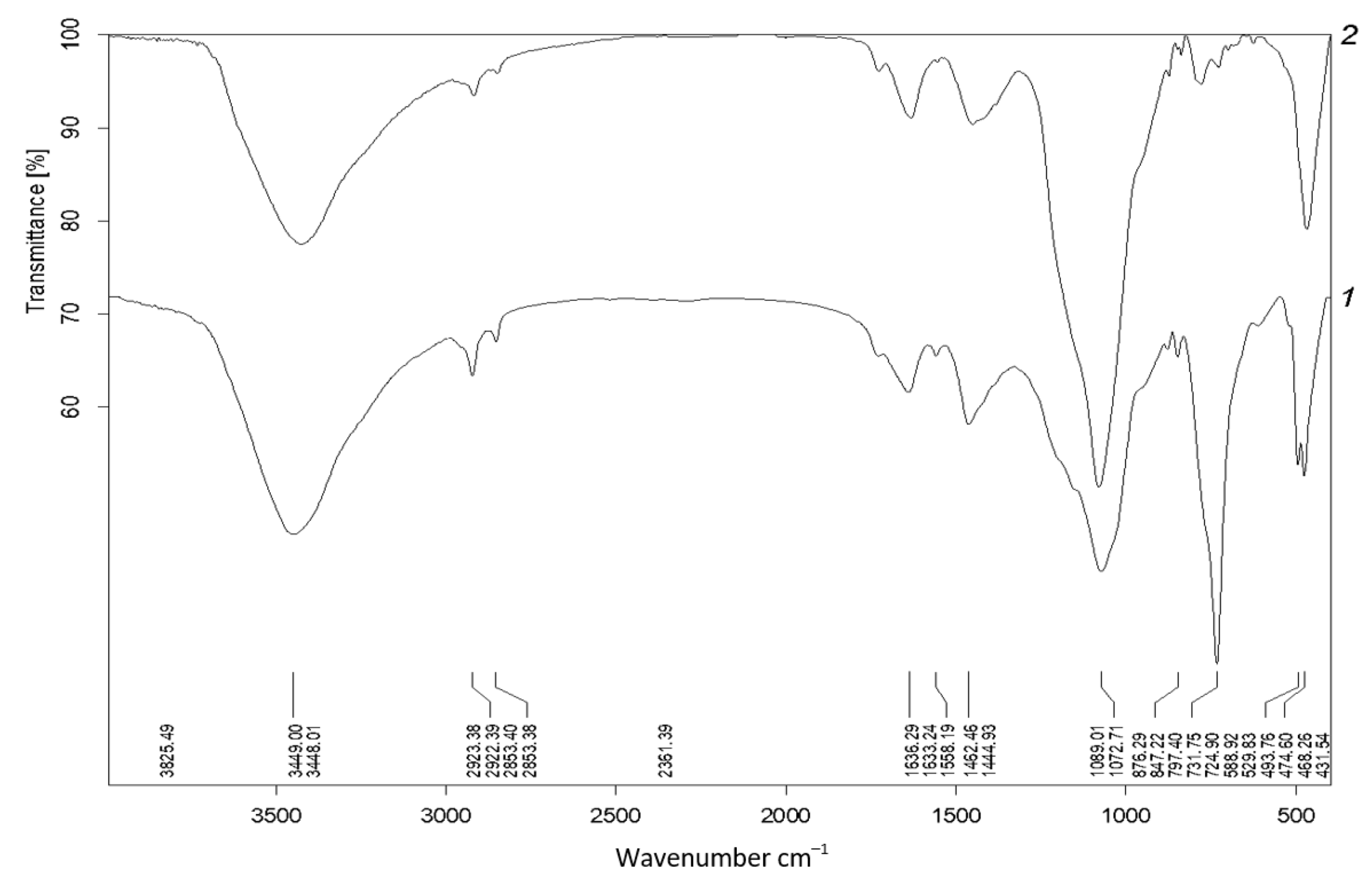
Figure 4 shows the IR absorption spectra of sodium silicate cured with sodium fluorosilicate without additives and with the addition of sulfonated naphthalene formaldehyde, slag and graphite.
For sodium silicate with a hardener, the following absorption bands were characteristic: 3200–3500 and 1635 cm−1—molecular water; 2700–3000 cm−1—hydrogen bonding; 1450–1460 cm−1—carbonate band vibrations; 1000–1200 cm−1—bond stretching vibrations Si–O; 770 cm−1—Si–O–Si symmetrical stretching of bridging oxygens between tetrahedra; 460–480 cm−1—deformation vibrations of the bond Si–O–Si. The high intensity of the band at 1100 cm−1, which corresponded to vibrations of the O–H bond in the Si-O-H groups, was apparently due to the polycondensation of HSiO43−, H3SiO4− and H4SiO4aq ions. Sodium silicate, approved by silicon-sodium fluoride, contained only condensed silicic tetrahedra (no band 900–1000 cm−1), but together with silicic acid can contain fluorides (400–600 cm−1) and silicon-fluoride (600–950 cm−1).
The following changes occurred in IR spectra of sodium silicate cured with sodium fluorosilicate and with additives of sulfonated naphthalene formaldehyde, slag and graphite: the intensity of the band at 730 cm−1 decreased significantly; the band at 493 cm−1 disappeared; and the band at 780 cm−1 appeared, which indicates the presence of the [AlO4]−4 group. An increase in intensity and a shift towards higher wavenumbers of the 1000–1100 cm−1 band were also observed.
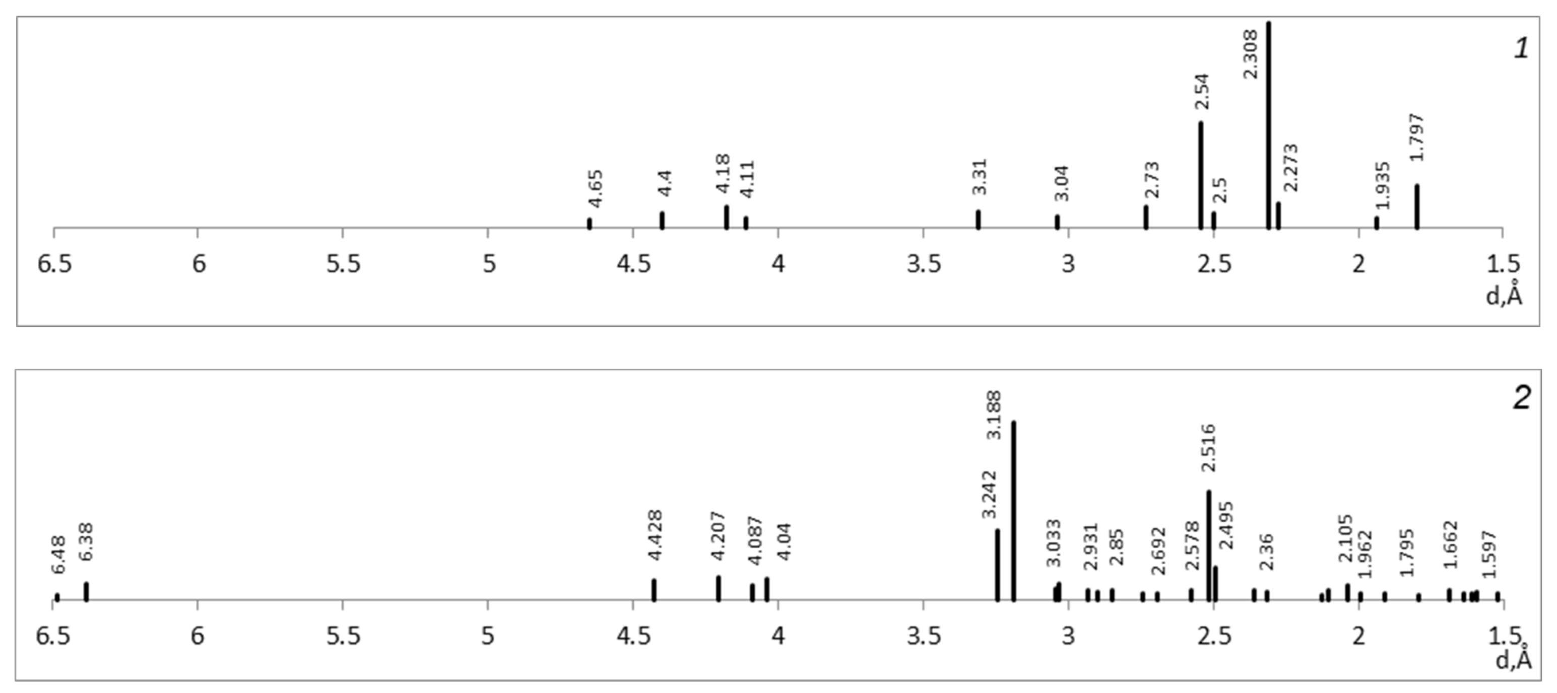
Figure 5 shows X-ray diffraction patterns of the respective composites. The X-ray diffraction pattern of sodium silicate cured with sodium silicon fluoride contained several distinct diffraction peaks, the combination of which suggests the presence of a significant amount of sodium fluoride (2.30 Å) and a small amount of sodium silicon fluoride (2.31; 3.31; 4.40 Å) and quartz (1.8; 2.27; 3.31 Å). Sodium silicon fluoride was the remainder of the original component; fragments of quartz-like structures could be formed as a result of the condensation of silicic acid. On the X-ray diffraction patterns of the composite containing graphite, diffraction maxima appearred 3.18–3.19; 3.24; 6.35–6.38; 6.47–6.48; 7.1 Å. Since they are typical for graphite, this confirms the hypothesis that there is no chemical interaction of graphite with sodium silicate and other components of the composite.
Analysis of the IR spectra and X-ray patterns generally confirmed the notion that sodium silicate cured with sodium fluorosilicate contains silicic acid gel and sodium fluoride. Sodium silicate, cured with sodium fluorosilicate with the addition of granulated blast-furnace slag, contains silicic acid, calcium and sodium hydroaluminosilicates and calcium hydrosilicates, but does not contain sodium fluoride. At the same time, calcium and sodium hydroaluminosilicates are contained less than in a composite of slag cured with sodium silicate (slag–alkali binder). The chemical interaction of graphite with sodium silicate and other components of the composite by physicochemical methods was not revealed. Therefore, graphite remained in an unbound state and retained electrical conductivity.
Figure 6 shows the data of scanning electron microscopy with X-ray microanalysis. Analysis of
Figure 6 shows that the surfaces of the cleavages of the composite are porous and rough, the graphite particles on the pictures are gray in color and have an amorphous structure, similar to the grains of metals (iron, chromium, titanium). However, graphite is difficult to identify because its surface is covered with small particles of the reaction products of sodium silicate and sodium silicon fluoride. It can be seen from the pictures that the structure of sodium silicate, cured with sodium silicon fluoride and with the addition of graphite, is dispersed, consists of gel-like formations and crystalline particles ranging in size from less than 1 micron to several microns, as well as inclusions of larger particles ranging in size from tens of microns to 100 microns. A joint analysis of the electron microscopic image and the X-ray surface map showed that sodium silicate cured with sodium fluorosilicate, with the addition of graphite, has the structure of a composite material with a filler of particles of graphite C (29%–33% of the surface) distributed over the volume. The composite matrix consists of the products of the interaction of sodium silicate and sodium fluorosilicate and includes elements such as O (45%–50%), Si (8%–11%), F (4%–5%), Na (1.4%), Al (1.2%–2%), Ca (0.9%–1.9%), etc. (less than 1% each), which are evenly distributed. It has been confirmed that due to the interaction of sodium silicate and sodium fluorosilicate, new products of predominantly gel-like structure are formed. There is no chemical interaction of sodium silicate and sodium fluorosilicate with graphite; graphite remains in an unbound state and retains electrical conductivity.
5. Discussion
We theoretically substantiated the creation of electrically conductive silicate composites for protection against the electrocorrosion of structures. An increase in water resistance was provided by the formation of insoluble zeolite-like sodium and calcium aluminosilicates.
The products of the interaction between silicate and sodium silicic fluoride are orthosilicic acid gel Si(OH)4 and sodium fluoride NaF, the particles of which have a negative surface charge and form non-water resistant electro-homogeneous contacts with each other. In the case of adding ground blast-furnace granulated slag, its compounds interact with NaF to form alkaline and alkaline earth hydroaluminosilicates, hydroaluminate C3AH6 and calcium fluoride CaF2. C3AH6 and CaF2 particles have a positive surface charge and form electro-heterogeneous contacts with Si(OH)4, which provide an increase in the water resistance of the composite. Thermodynamic calculations were performed to establish the possibility of the formation of hydronepheline NAS2H2, calcium hydroaluminate C3AH6 and calcium fluoride CaF2 due to the interaction of slag with sodium fluoride NaF.
It has been experimentally established that the electrophysical properties of the composite are in antagonism with the physico-mechanical and hydrophysical ones; therefore, the development of its composite should be carried out using methods of compromise optimization. The specific electrical resistance of the composite r depends on the content of graphite G/(G + S) and sodium silicate Wg/(G + S); the minimum r = 0.2–1 Ω × m is observed for G/(G + S) = 0.2–0.8 and CH/(G + S) = 0.4–0.9. The water resistance of Kwr depends mainly on Wg/(G + W) and is maximum (up to 0.8) at Wg/(G + W) = 0.3–1.0 and G/(G + W) close to 0.7. In a composite that contains only graphite as a filler, shrinkage cracks are formed. The introduction of slag in an amount of at least 0.1 of sodium silicate prevents their formation.
As a result of physical and chemical studies, it was confirmed that the products of the interaction of silicate and sodium fluorosilicate are Si(OH)4 and NaF, and with the addition of slag, the products are Si(OH)4, calcium and sodium hydroaluminosilicates and calcium hydrosilicates. As a result of electron microscopic studies, it was found that the composite has the structure of a matrix composite with a filler of uniformly distributed graphite and a matrix of hardening products with a predominantly gel-like structure. The chemical interaction of graphite with the components of the composite was not found; therefore, graphite remained in an unbound state and retained electrical conductivity.


