Article

Study on the Aeromagnetic System between Fixed-Wing UAV and Unmanned Helicopter

1
Institute of Geophysical and Geochemical Exploration, Chinese Academy of Geological Sciences (CAGS), Langfang 065000, China
2
Key Laboratory of Geophysical Electromagnetic Probing Technologies, Ministry of Natural Resources (MNR), Langfang 065000, China
*
Authors to whom correspondence should be addressed.
Minerals 2023, 13(5), 700; https://doi.org/10.3390/min13050700
Submission received: 24 April 2023 / Revised: 12 May 2023 / Accepted: 18 May 2023 / Published: 20 May 2023
(This article belongs to the Special Issue Gravity and Magnetic Methods in Mineral Exploration)

Abstract

:
Based on the CH-3 and WH-110A unmanned aerial vehicle (UAV) platforms, we independently developed aeromagnetic systems for fixed-wing UAVs (FUAV) and modified unmanned helicopters (MUH), respectively. These systems overcome key technological challenges in system integration, aeromagnetic compensation, and electromagnetic (EM) compatibility. We conducted a 1:100,000 aeromagnetic test using both systems in a tidal flat area in Jiangsu province, China. Both systems successfully completed 240 line km measurement lines and collected high-quality data with magnetic compensation accuracies of 0.01428 nT and 0.04690 nT, respectively. The dynamic noise was below 0.14 nT, accounting for 95.72% and 100% of the measurements. These results indicate that both systems offer high measurement accuracy, efficiency, low cost, convenience, and flexibility. We compared the two aeromagnetic systems based on their system parameters, integration modes, magnetic compensation methods and effects, and practical applications. By comprehensively analyzing their characteristics and application fields, we provide guidance for UAV-based aeromagnetic surveys in mineral exploration, basic geological survey and other related fields. And the FUAV and MUH aeromagnetic systems presented in this paper serve as a valuable reference for future research in this area.

1. Introduction

UAV technology has developed rapidly in the past two decades and is now widely used in geological prospecting [1,2,3], remote sensing [4,5,6], unexploded ordnance (UXO) detection [7,8,9], and environmental monitoring [10,11,12]. Among these applications, UAV aeromagnetic surveys have emerged as a popular branch of airborne geophysical technology due to their convenient deployment, low cost, intelligence, and high precision. This technology has attracted significant attention from geophysical companies and scholars worldwide.
After 2000, numerous studies on UAV aeromagnetic survey technology were initiated. In 2003, Magsurvey Ltd. in the UK developed the PrionUAV aeromagnetic system [13]. In 2004, Fugro in the Netherlands modified the aeromagnetic system of ScanEagle Georanger-I high-precision UAV with the help of Insitu [14,15,16]. In 2005, Canada Universal Wing Geophysics integrated the cesium optical pumping magnetometer into the Venturer UAV to form a UAV aeromagnetic system [13,17]. From 2009 to 2012, Canada Carlton University developed the Geosurv UAV aeromagnetic system, and carried out flight tests in 2013 [18]. In 2010, German MGT used the MD4-1000 unmanned helicopter (UH) with a miniaturized fluxgate magnetometer for UXO and landslide detection and developed unmanned aircraft systems (UAS) in 2013 that could simultaneously measure the EM fields and magnetic fields [19]. In 2012, Japan developed some aeromagnetic systems based on the UH platforms for the precise aeromagnetic survey [20,21]. In 2019, German Sensys Company launched the MagDrone-R3/R4 UAV aeromagnetic measurement system. In 2021, Martelet et al. conducted a multi-sensor (multispectral and magnetic) UAV survey to address detailed geological mapping and modeling of mineralization in geological environment [22]. In 2022, Phelps et al. used a multirotor UAV equipped with magnetic sensors to study magnetic compensation models and measurement accuracy, which can reach sub-nT [23]. In China, Zhang, Fan, and Xiong systematically summarized the progress of airborne geophysical exploration both domestically and abroad [24,25]. From 2008 to 2011, several companies and institutions began studying FUAV aeromagnetic systems, including the 715 Research Institute of China Shipbuilding Industry Corporation, the Institute of Remote Sensing and Digital Earth (RADI) of Chinese Academy of Sciences (CAS), the China Aero Geophysical Survey and Remote Sensing Center for Land and Resources (AGRS), and Beijing Laurel Technologies Company Ltd. These organizations conducted research but did not carry out any practical application surveys [26,27]. In 2012, Peking University and other institutes also conducted similar research and obtained some test data, but these aeromagnetic systems were not widely adopted [28]. In 2014, Beijing Orangelamp Geophysical Exploration Co., Ltd. integrated a fluxgate magnetometer into a multirotor UAV and an FUAV to develop UAV aeromagnetic systems that were lightweight but low precision. In recent years, aeromagnetic measurement systems based on multirotor UAVs and compound wing UAVs have also emerged [29,30,31,32,33,34].
At present, most FUAV platforms are medium- or large-sized and have low flight height, high precision, high speed, and high efficiency. These characteristics make them suitable for large-area aeromagnetic surveys, but they require an airport runway. In contrast, UHs have advantages over FUAVs in terms of ultralow flight height, low-speed cruising, and maneuverability and do not require an airport runway. This makes them suitable for large-scale and small-area aeromagnetic surveys. However, further research is needed to improve this technology in China.
In 2013, we overcame some key technologies in UAV system integration and magnetic compensation and integrated an aeromagnetic instrument into the CH-3 FUAV to create a medium-sized FUAV aeromagnetic system, the first in China [26]. We carried out several geological survey applications and demonstrations in Northeast and Northwest China and obtained high-quality data and good geological results [28,35,36,37]. In 2017, with the help of the Coal Geological Geophysical Exploration Surveying & Mapping Institute of Shanxi Province, we developed a MUH aeromagnetic system based on the WH-110A MUH. We conducted a flight test in a tidal flat area in Jiangsu province in eastern China and achieved good practical application results [38,39]. In this paper, we compare the FUAV and MUH aeromagnetic systems that we developed independently. We analyze their system parameters, integration modes, magnetic compensation methods and effects, and practical applications and discuss their advantages and disadvantages.

2. UAV Aeromagnetic System

2.1. FUAV Aeromagnetic System

CH-3 FUAV is a medium-sized commercial drone, developed and manufactured by Aerospace CH UAV Co., Ltd., in Beijing, China. It has a wingspan of 8 m, a takeoff weight of 640 kg, and a payload capacity of up to 160 kg. Its cruising speed is 170–200 km/h it has a flight time of about 10 h, and the magnetic interference is lower than 10 nT. The engine performance and the reliability of the measurement and control system are stable, and the FUAV has the capabilities of ultralow flight height, night flight, and autonomous return when lost.
The FUAV aeromagnetic system we developed mainly consists of the CH-3 FUAV platform, ground measurement and control system, CS-3/CS-VL magnetometer (Canada Scintrex Company, Concord, ON, Canada), aeromagnetic compensation, and recorder, as shown in Figure 1. Through an improved data acquisition and processing system, the FUAV aeromagnetic system realizes synchronous data acquisition and processing using FUAV differential GPS (DGPS) positioning. The refresh frequency of positioning data can reach 5 Hz, effectively improving positioning accuracy. With the interface hardware circuit and measurement and control software, the FUAV aeromagnetic system is very flexible and can be equipped with different aeromagnetic data acquisition and compensation systems, such as AARC51, AARC500, AARC510, and DAARC510 (Canada RMS Instruments Ltd., Mississauga, ON, Canada). Additionally, based on the radio measurement and control system, a satellite measurement and control communication protocol of the airborne magnetometer is established and a dual measurement and control mode with maritime satellite and radio is integrated to improve the flight radius of the FUAV aeromagnetic system. The system can simultaneously measure the total magnetic intensity (TMI) and the horizontal gradient of the magnetic field, achieving good results in practical applications.

2.2. MUH Aeromagnetic System

The MUH aeromagnetic system uses the WH-110A UH, which is modified by Beijing Fangxin Technology Co., Ltd., in Beijing, China based on an imported drone. The rotor diameter is 3.2 m, the fuselage height is 1.01 m, the fuselage width is 0.72 m, and the total length is 3.81 m. The maximum cruising speed is 60 km/h; the flight duration is 3 h. The payload can reach 35 kg and the maximum takeoff weight is 110 kg. The maximum flight height is 3000 m, and the maximum permissible wind speed can reach 15 m/s. The control system uses DGPS to achieve adaptive flight control navigation, providing high-precision positioning hovering and intelligent autonomous flight on preset routes.
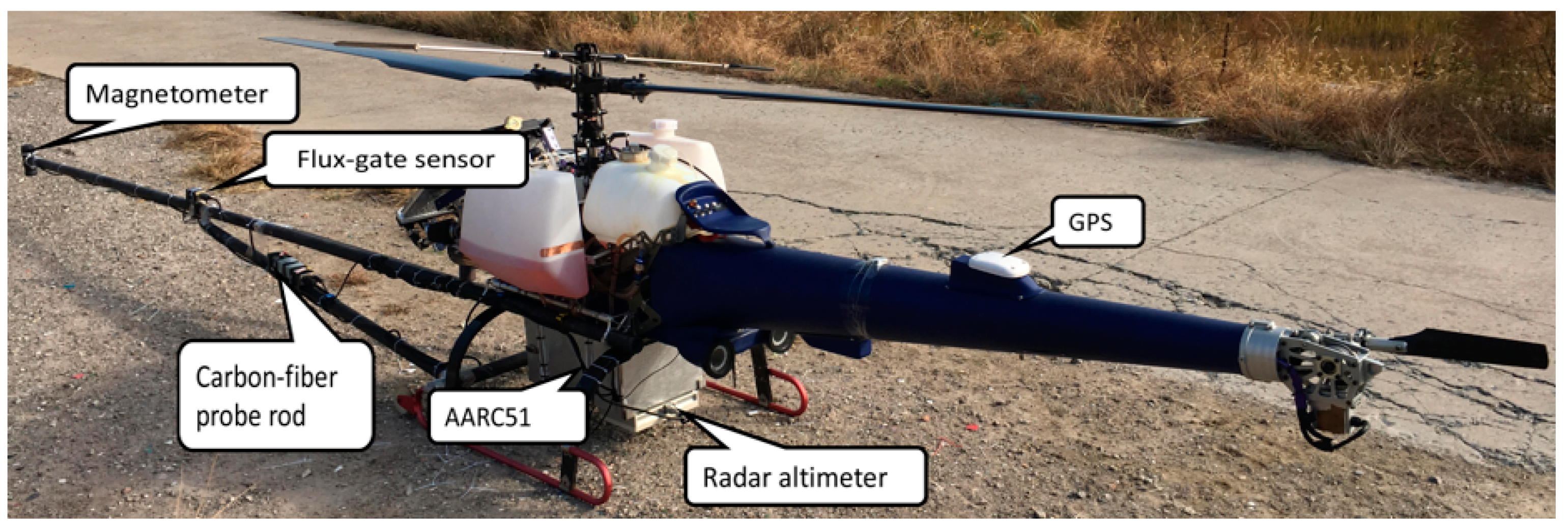
The aeromagnetic system installed on MUH mainly consists of a CS-VL high-precision cesium optical pumping magnetometer, an AARC51 adaptive aeromagnetic compensation and data recorder, a barometric altimeter, a radar altimeter and a GPS navigation and positioning system. The total weight is less than 5 kg, making it particularly suitable for drones, as shown in Figure 2. The MUH aeromagnetic system can collect data for the automatic compensation of magnetic fields, TMI, longitude and latitude, flight height, and flight direction. A comparison of the main parameters between the FUAV and MUH aeromagnetic systems discussed in this paper is shown in Table 1.

3. Aeromagnetic Compensation

In aeromagnetic surveys, the change in flight direction and motion attitude can cause magnetic interference from the aircraft’s magnetic elements to be superimposed on the collected magnetic field. To reduce this magnetic interference and improve the accuracy of aeromagnetic measurements, magnetic compensation is necessary.

3.1. FUAV Aeromagnetic System

To address the magnetic interference of the CH-3 FUAV, we propose a solution and modify the system to eliminate and weaken static EM interference. Firstly, we measured the background field of the FUAV and installed the magnetometer at the wingtip where the magnetic field gradient is the smallest. Secondly, we checked and replaced all replaceable interference parts with nonmagnetic materials such as pure copper and plastic screws. Finally, we used comprehensive technologies such as EM shielding, electrical isolation, and weak magnetization of interference sources. Figure 3 shows an example of the magnetic interference of the FUAV before and after the magnetic field weakening. The noise level dropped to near zero, indicating that our methods can effectively reduce the magnetic interference of the FUAV.
The magnetic compensation method and technical process are as follows: firstly, a rectangular area is chosen where the change of magnetic field does not exceed 200 nT. Secondly, the aircraft flies for about 120 s at a height of 2 to 3 km along the four sides of the area in the directions of 0°, 90°, 180°, and 270°, or the directions of measuring line and cross line. The aircraft rolls (±10°), pitches (±5°), and sideslips (±5°) in each direction with 5 to 6 repetitions to obtain relevant data between aircraft magnetic interference and flight attitude. Finally, the coefficients of the magnetic compensation models are calculated for real-time or post-magnetic compensation [40]. To meet these technical requirements, we introduced a magnetic compensation flight approach in the flight control system for accurate flight attitude control of the FUAV. We strictly controlled the maneuvering range of the FUAV by controlling the turning radius and encrypting the route point to avoid losing data during compensation flight. This solved the technical problem of nonstandard magnetic compensation flight maneuver for FUAVs. Figure 4 shows the magnetic compensation track of the FUAV aeromagnetic system.

3.2. MUH Aeromagnetic System

The MUH’s interference in the aeromagnetic measurement is mainly caused by its engine. Therefore, we use a 3.5 m carbon-fiber probe rod to distance the magnetometer from the fuselage to the furthest extent possible and employ a triangular support structure to enhance stability. Furthermore, aside from key components of the MUH, we replace the remaining constituents with nonmagnetic or weak magnetic materials, e.g., a plastic fuel tank, an aluminum container for the instruments, and pure copper screws, to negate and weaken the magnetic interference.
Due to the differences in control modes between the small UH and manned aircraft or medium–large FUAV, small UHs can meet flight height requirements in autopilot mode, but their measurement and control systems cannot complete the required actions. After extensive analysis and testing, we propose a solution: choose a rectangular area with a stable magnetic field and manually control the small UH to complete the required actions in four directions, with 3–5 repetitions in each direction, within a line-of-sight distance of 300 to 500 m and a total time of 6–8 min. This process, which takes the direction of the aircraft nose as the reference direction and is shown in Figure 5, meets the requirements for magnetic compensation of rolling, pitching, and yawing of the small UH aeromagnetic system.

3.3. Aeromagnetic Compensation Test

We carried out a magnetic compensation test of the FUAV and MUH aeromagnetic system in a tidal flat area of Jiangsu province, China and obtained good results. Table 2 shows the magnetic compensation results: the comp values for the FUAV and MUH aeromagnetic systems are 0.01428 nT and 0.04690 nT, respectively, both meeting the technical requirement of less than 0.08 nT. The norm value for the FUAV aeromagnetic system is nearly four times that of the MUH aeromagnetic system, indicating that the former system is more difficult to compensate due to its complex system structure. However, both systems meet the technical requirement of less than 100.
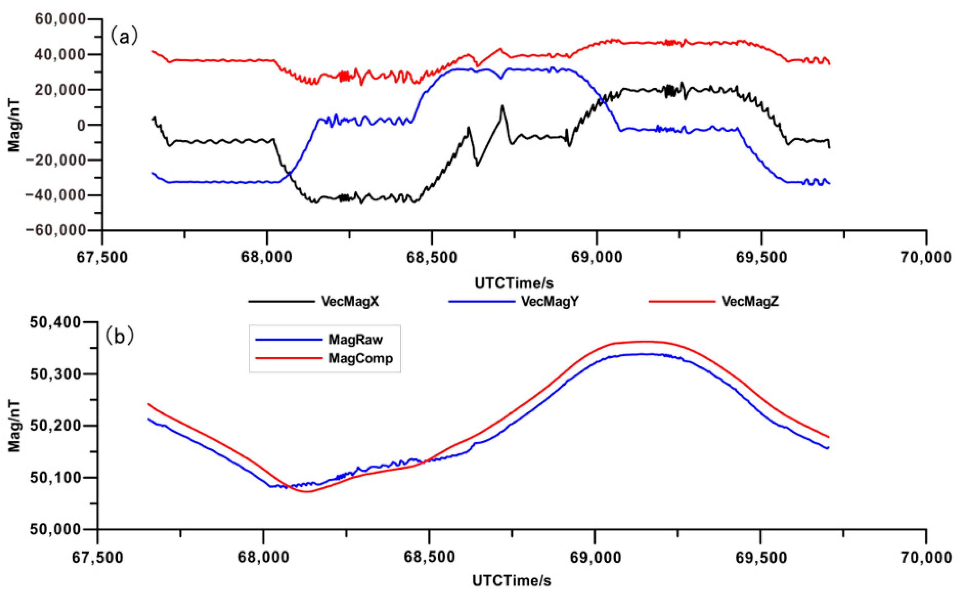
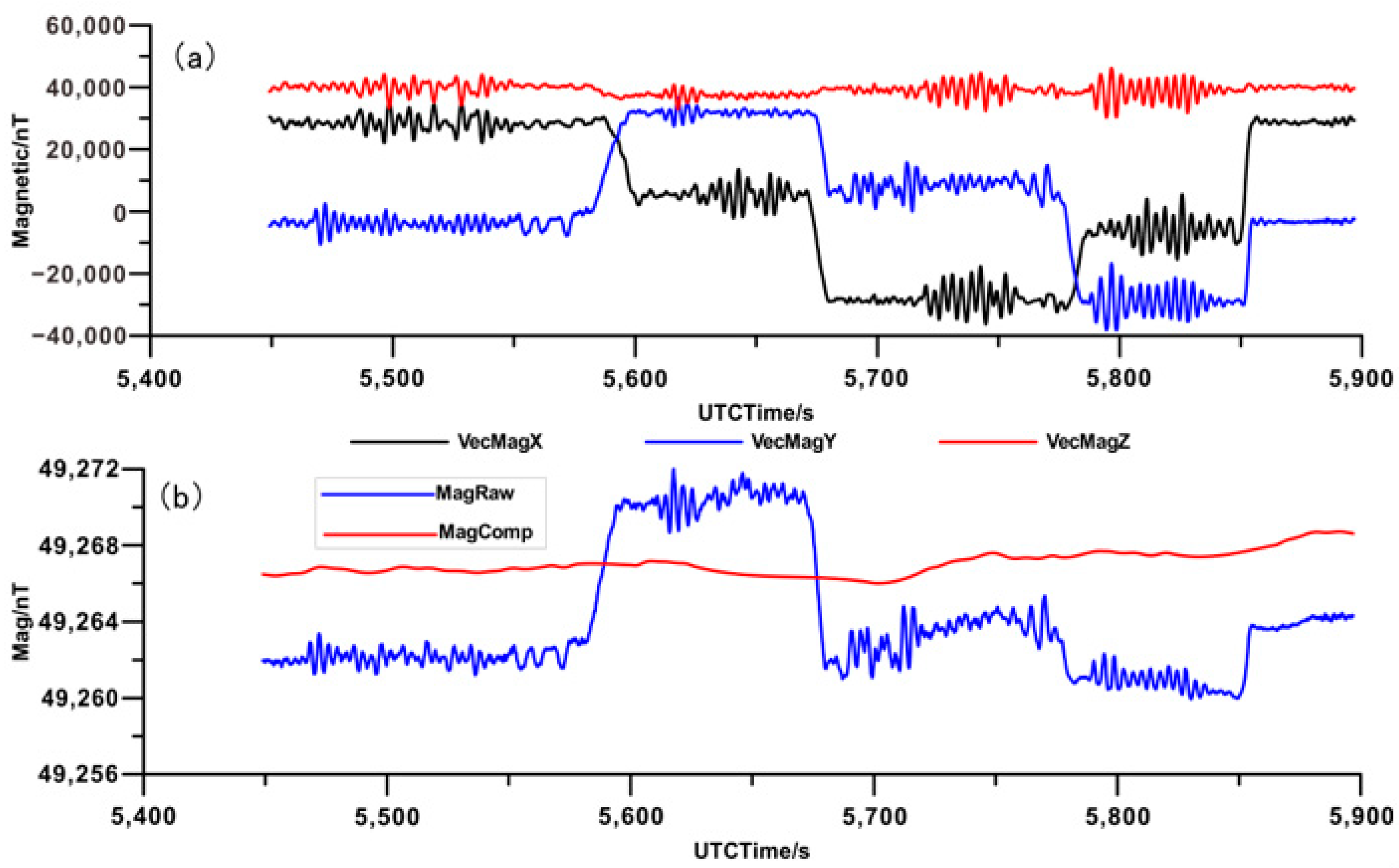
Figure 6 and Figure 7 illustrate the magnetic compensation test of the FUAV and MUH aeromagnetic systems, respectively. As depicted in Figure 6a and Figure 7a, the variations in magnetic field data curves of X, Y, and Z components effectively reflect the rotation, roll and pitch actions of the drones in four directions. However, due to the unknown interference during the test, the compensation actions of the FUAV aeromagnetic system are less standardized than those of the MUH aeromagnetic system. The results before and after magnetic compensation in Figure 6b and Figure 7b demonstrate that the magnetic interference caused by flight attitude is effectively removed after magnetic compensation, resulting in smoother magnetic field data curves.

4. Application Test

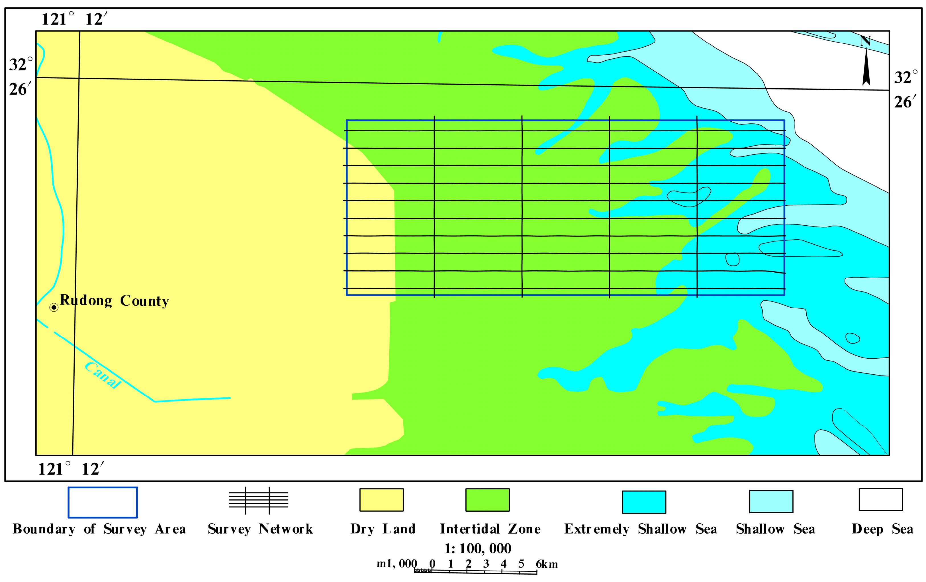
We conducted an aeromagnetic test survey using both the FUAV and MUH aeromagnetic systems in a tidal flat area in Jiangsu province, China (Figure 8). The majority of the survey area consists of coastal tidal flats, with a few extremely shallow sea areas located in the east. The western tidal flats are covered by a thick overburden formed by Quaternary (Q) loose sediments and Neogene (N) clay, with bedrock depths generally exceeding 600 m. Additionally, there are some power-generating windmills on the eastern beach and shallow sea. The survey includes 10 aeromagnetic measurement lines spanning 200 line km with a line spacing of 1.0 km and 4 crosslines spanning 40 line-km, with a line spacing of 5.0 km. The aeromagnetic measurement scale is 1:100,000.
Both aeromagnetic systems completed 240 line km measuring lines. For the FUAV aeromagnetic system, the average flight height was 199 m and the dynamic noise level ranged from 24.794 to 95.412 pT. First-class (≤0.08 nT) and second-class (>0.08 nT and ≤0.14 nT) data account for 95.72% of the total, with no data below third-class (>0.14 nT and ≤0.20 nT). For the MUH system, the average flight height was 119 m and the dynamic noise level ranged from 10.0 to 15.0 pT, reaching first-class level. Both aeromagnetic systems collected high-quality data, demonstrating their effectiveness and reliability for aeromagnetic surveys.
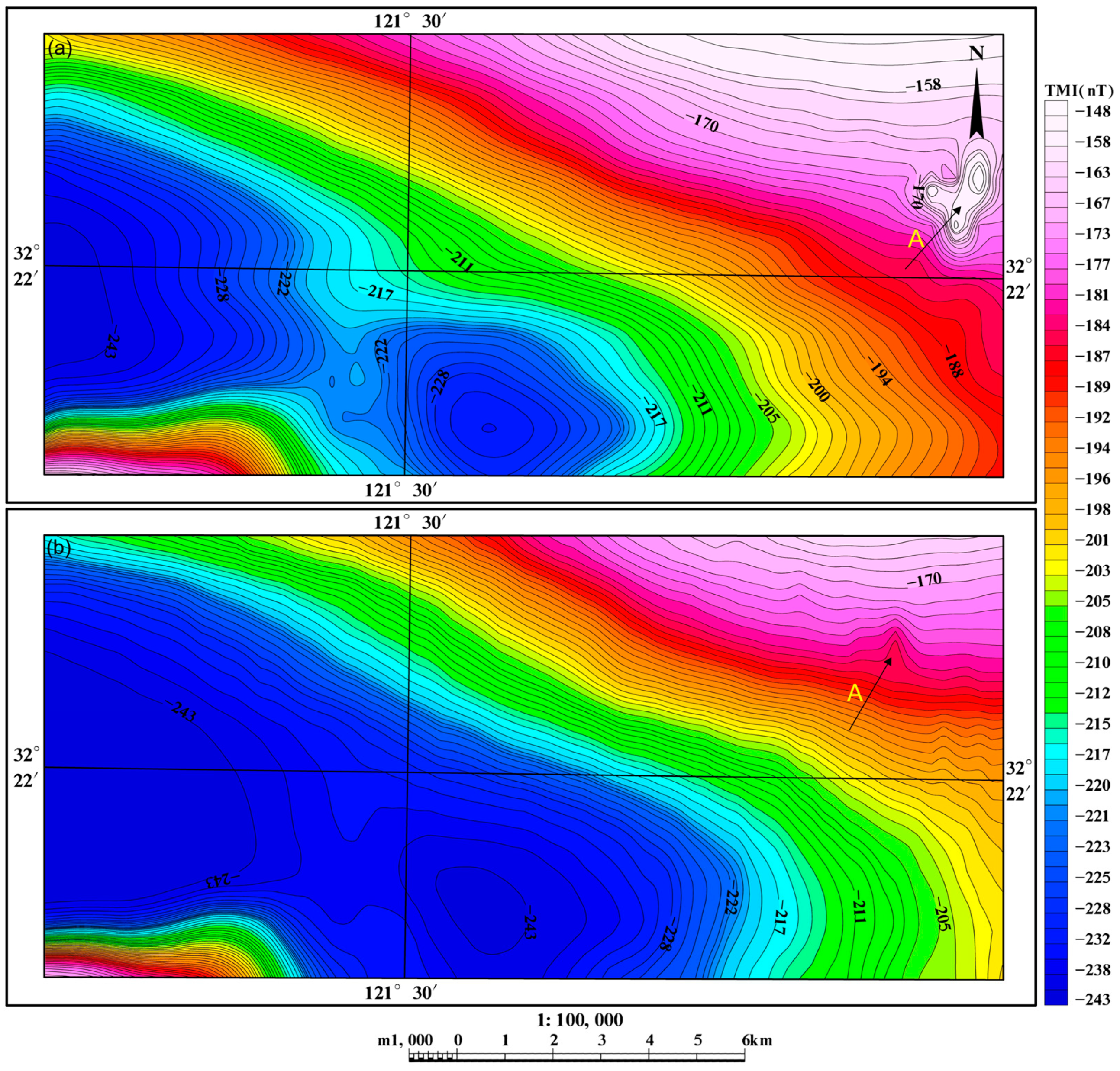
Figure 9 compares the TMI contour maps after IGRF correction from aeromagnetic surveys conducted using the FUAV and MUH systems. The distribution and location of magnetic anomalies measured using both systems are almost identical. However, there are two main differences: the amplitude of TMI measured using the FUAV system is lower than that measured by the MUH system due to its higher flight height; for the magnetic anomalies indicated by arrow A, the amplitude of TMI measured using the FUAV system is much higher than that measured using the MUH system, as shown more clearly in Figure 9a. We believe that these magnetic anomalies may be caused by strong magnetic interference from the power-generating windmills in the area, with greater impact on the FUAV system because it flies above the windmills while the MUH system flies below them during aeromagnetic surveys.

5. Discussion

Both the FUAV and MUH aeromagnetic systems we developed achieved good application results in aeromagnetic surveys, providing a high-precision, high-efficiency, and high-flexibility means for geological survey and mineral exploration. However, both systems have their advantages and disadvantages.
(1) For high-precision measurement, both systems can fly autonomously according to the predesigned measurement lines using the DGPS flight control navigation system. The maintenance of yaw and flight height is much better than that of traditional manned aircraft. Additionally, the aeromagnetic recording system can collect DGPS data synchronously, and its 5 Hz sampling rate effectively improves the positioning accuracy of aeromagnetic data and anomaly interpretation.
Both the magnetic compensation control software for the medium–large FUAV system and the hovering magnetic compensation technology for the UH system, which we developed independently, can meet the quality requirements of the aeromagnetic surveys and effectively ensure the quality of aeromagnetic data.
(2) In terms of work efficiency, the FUAV system has good night flight capability and can work 24 h a day under the permission of weather, airspace, and other conditions. Although the MUH system has a flight duration of only about 3 h, it can still conveniently complete multiple flight missions each day due to its simple and quick refueling process and small 8 × 8 m landing area. Therefore, both systems can work efficiently.
(3) In terms of application area and applicability, the FUAV system has dual radio and maritime satellite measurement and control systems, enabling it to operate in areas inaccessible to set the control station, such as open sea, desert, and no man’s land. With its fast flight speed, it is more suitable for large area fast scanning and long-distance tasks. The MUH system, due to its small payload, can only carry a radio measurement and control system and has a smaller measurement and control area. Its slow flight speed and dense sampling points make it more suitable for fine magnetic measurement tasks in small areas.
(4) In terms of work cost, the FUAV system’s drone, measurement instruments, and control systems are more complex, requiring more maintenance and technicians, an at least 800 m runway for takeoff and landing, and airport support. In contrast, the MUH system only requires two flight controllers to operate and can take off and land on a relatively flat and open ground without the runway, resulting in lower work costs, approximately FUAV:MUH = 2:1 in this paper.
(5) In terms of data acquisition, the FUAV system has two magnetometers on its wingtips that can simultaneously collect TMI and horizontal gradient data. This effectively suppresses interference, highlights magnetic anomalies, and provides more effective data parameters for geological interpretation.

6. Conclusions

In this paper, we independently developed the FUAV and MUH aeromagnetic systems and compared their system parameters, integration modes, magnetic compensation methods and effects, and practical applications. We also analyzed their advantages and disadvantages. In practical application, both systems obtained high-quality and high-precision magnetic field data that met the technical requirements for the aeromagnetic surveys. This provides a reference for efficient and convenient UAV geophysical surveys.
In the near future, we believe that drones will be able to perform real-time terrain scanning to improve their terrain-following capabilities and work in a complex terrain environment. Our next step will be to develop and improve the real-time data transmission system based on the characteristics of different types of drones and geophysical instruments. This will enable real-time monitoring of the quality and validity of measured data and reduce economic losses caused by instrument faults. With the development of drone technology, airborne geophysical systems will evolve into multiparameter integrated systems (e.g., airborne EM, gravity, magnetic, radioactivity) to promote the widespread use of UAV airborne geophysical technology in mineral exploration, environmental monitoring, and basic geological survey.

Author Contributions

Conceptualization, Y.-Z.X., Y.-B.L. and N.L.; methodology, Y.-Z.X. and G.-X.L.; software, Y.-Z.X. and S.W.; investigation and validation, Y.-Z.X., G.-X.L. and S.W.; writing—original draft preparation, Y.-Z.X. and Y.-B.L.; writing—review and editing, all participants; supervision, G.-X.L. and S.W. All authors have read and agreed to the published version of the manuscript.

Funding

This research was funded by the National Key Research and Development Program (grant number 2017YFC0602004) and the Basic Scientific Research Project of the Chinese National Nonprofit Institute (grant number AS2017Y04 and AS2022J01).

Data Availability Statement

Not applicable.

Acknowledgments

We are thankful for the constructive comments of the editors and anonymous reviewers that improved this paper. We are also grateful for the help from Qing-min Meng, Fei Li, and Jun-jie Liu in data acquisition and system development.

Conflicts of Interest

The authors declare no conflict of interest.

References

  1. Šálek, O.; Matolín, M.; Gryc, L. Mapping of radiation anomalies using UAV mini-airborne gamma-ray spectrometry. J. Environ. Radioact. 2018, 182, 101–107. [Google Scholar] [CrossRef] [PubMed]
  2. Parshin, A.; Bashkeev, A.; Davidenko, Y.; Persova, M.; Iakovlev, S.; Bukhalov, S.; Grebenkin, N.; Tokareva, M. Lightweight Unmanned Aerial System for Time-Domain Electromagnetic Prospecting—The Next Stage in Applied UAV-Geophysics. Appl. Sci. 2021, 11, 2060. [Google Scholar] [CrossRef]
  3. Parshin, A.; Morozov, V.; Snegirev, N.; Valkova, E.; Shikalenko, F. Advantages of Gamma-Radiometric and Spectrometric Low-Altitude Geophysical Surveys by Unmanned Aerial Systems with Small Scintillation Detectors. Appl. Sci. 2021, 11, 2247. [Google Scholar] [CrossRef]
  4. Niethammer, U.; James, M.; Rothmund, S.; Travelletti, J.; Joswig, M. UAV-based remote sensing of the Super-Sauze landslide: Evaluation and results. Eng. Geol. 2012, 128, 2–11. [Google Scholar] [CrossRef]
  5. Salamí, E.; Barrado, C.; Pastor, E. UAV Flight Experiments Applied to the Remote Sensing of Vegetated Areas. Remote Sens. 2014, 6, 11051–11081. [Google Scholar] [CrossRef]
  6. Yao, H.; Qin, R.; Chen, X. Unmanned Aerial Vehicle for Remote Sensing Applications—A Review. Remote. Sens. 2019, 11, 1443. [Google Scholar] [CrossRef]
  7. Gavazzi, B.; Le Maire, P.; Munschy, M.; Dechamp, A. Fluxgate vector magnetometers: A multisensor device for ground, UAV, and airborne magnetic surveys. Lead. Edge 2016, 35, 795–797. [Google Scholar] [CrossRef]
  8. Qi, Z.P.; Li, X.; Li, H.; Liu, W.T. First Results From Drone-Based Transient Electromagnetic Survey to Map and Detect Unexploded Ordnance. IEEE Geosci. Remote Sens. Lett. 2020, 17, 2055–2059. [Google Scholar] [CrossRef]
  9. Bajić, M., Jr.; Bajić, M. Modeling and simulation of very high spatial resolution UXOs and landmines in a hyperspectral scene for UAV survey. Remote Sens. 2021, 13, 837. [Google Scholar] [CrossRef]
  10. Villa, T.F.; Gonzalez, F.; Miljievic, B.; Ristovski, Z.D.; Morawska, L. An overview of small unmanned aerial vehicles for air quality measurements: Present applications and future prospectives. Sensors 2016, 16, 1072. [Google Scholar] [CrossRef]
  11. Kislik, C.; Dronova, I.; Kelly, M. UAVs in support of algal bloom research: A review of current applications and future opportunities. Drones 2018, 2, 35. [Google Scholar] [CrossRef]
  12. Cheng, L.; Tan, X.; Yao, D.; Xu, W.; Wu, H.; Chen, Y. A fishery water quality monitoring and prediction evaluation system for floating UAV based on time series. Sensors 2021, 21, 4451. [Google Scholar] [CrossRef] [PubMed]
  13. Patrick, G.; Killen, P.D. Exploration trends and developments in 2005. Can. Min. J. 2006, 10. [Google Scholar]
  14. Lum, C.W.; Rysdyk, R.T.; Pongpunwattana, A. Autonomous Airborne Geomagnetic Surveying and Target Identification. Am. Inst. Aeronaut. Astronaut. 2005, 1–12. [Google Scholar] [CrossRef]
  15. Partner, R. Georanger Aeromagnetic UAV—From Development to Commercial Survey. Preview Aust. Soc. Explor. Geophys. 2006, 125, 28–29. [Google Scholar]
  16. Barnard, J. Use of Unmanned Air Vehicles in Oil, Gas and Mineral Exploration Activities. In Proceedings of the AUVSI Unmanned Systems North America 2010 Conference, Denver, CO, USA, 26 August 2010. [Google Scholar]
  17. Patrick, G.; Killeen, P.D. Exploration trends and developments in 2004. Can. Min. J. 2005, 9. [Google Scholar]
  18. Lalibertee, J. Carleton University Fixed Wing Uav Project. Ph.D. Thesis, Carleton University, Ottawa, NA, Canada, 2013. [Google Scholar]
  19. Stoll, J.B. Unmanned Aircraft System for Rapid Near Surface Geophysical Measurements. International Archives of the Photogrammetry. Remote Sens. Spat. Inf. Sci. 2013, XL-1/W 2, 391–394. [Google Scholar]
  20. Hitoshi, M.; Satoshi, T.; Yumiko, O.; Shigeo, M.; Masayuki, S.; Eri, O.; Takuya, S.; Isamu, Y.; Shigekazu, K.; Tatsuya, N.; et al. A Development of Airborne survey of Gravity and Magnetics on an unmanned helicopter and its data processing. In Proceedings of the Japan Geoscience Union meeting, Toyko, Japan, 22 May 2013. [Google Scholar]
  21. Shin’ya, A.; Minoru, F.; Shin-ichiro, H.; Norihiro, N.; Naoyoshi, I.; Noriaki, O.; Mikio, K. Aeromagnetic survey by a small unmanned airplane over northern part of Deception Island. In Proceedings of the Japan Geoscience Union meeting, Toyko, Japan, 22 May 2013. [Google Scholar]
  22. Martelet, G.; Gloaguen, E.; Døssing, A.; Lima Simoes da Silva, E.; Linde, J.; Rasmussen, T.M. Airborne/UAV Multisensor Surveys Enhance the Geological Mapping and 3D Model of a Pseudo-Skarn Deposit in Ploumanac’h, French Brittany. Minerals 2021, 11, 1259. [Google Scholar] [CrossRef]
  23. Phelps, G.; Bracken, R.; Spritzer, J.; White, D. Achieving sub-nanoTesla precision in multirotor UAV aeromagnetic surveys. J. Appl. Geophys. 2022, 206, 104779. [Google Scholar] [CrossRef]
  24. Zhang, H.R.; Fan, Z.G. Recent Advances in Aerogeophysical Techniques Used Abroad. Geophys. Geochem. Explor. 2007, 31, 451–457. [Google Scholar]
  25. Xiong, S.Q. The Advances of Aerogeophysical Survey in China Since the Tenth Five Year Plan and Its Development Trend. Geophys. Geochem. Explor. 2007, 31, 479–484. [Google Scholar]
  26. Li, W.J.; Li, F.; Liu, S.K.; Zhou, N.E. The Progress in the Development of the Integrated UAV Magnetic & Radiation Survey System. Acta Geosci. Sin. 2014, 35, 399–403. [Google Scholar]
  27. Chinese Academy of Geological Sciences. Top Ten Scientific and Technological Progress of Chinese Academy of Geological Sciences in the Year 2013 Unveiled. Acta Geosci. Sin. 2014, 35, 1–5. [Google Scholar]
  28. Li, F.; Ding, Z.Q.; Cui, Z.Q.; Xu, Z.L.; Li, J.F. Application Demonstration of the CH-3 UAV-borne Magnetic Survey System in Different Terrain Areas of Xinjiang. Geol. Explor. 2018, 54, 735–746. [Google Scholar]
  29. Cui, Z.Q.; Xu, Z.L.; Li, J.F.; Li, F. The R&D Application of UAV Airborne Geophysical Survey and Its Development Trend. Comput. Tech. Geophys. Geochem. Explor. 2016, 38, 740–745. [Google Scholar]
  30. Du, J.Q. Research on Data Acquisition System of Aeromagnetic Three-component Based on Rotor UAV. Ph.D. Thesis, Jilin University, Jilin, China, 2021. [Google Scholar]
  31. Zheng, Y.; Li, S.; Xing, K.; Zhang, X. Unmanned Aerial Vehicles for Magnetic Surveys: A Review on Platform Selection and Interference Suppression. Drones 2021, 5, 93. [Google Scholar] [CrossRef]
  32. Zhou, P.Z.; Tang, M.Q.; Liu, D.R.; Wei, W.; Peng, C. Application Research of New Domestic UAV Aeromagnetic System. Hydrogr. Surv. Charting 2022, 42, 30–35. [Google Scholar]
  33. Qiao, Z.K.; Yuan, P.; Wang, L.F.; Zhang, Z.H.; Huang, Y.S.; Zhang, J.J.; Li, L.L.; Zhang, Z.Y.; Wu, B.; Lin, Q. Research on aeromagnetic compensation of a multi-rotor UAV based on robust principal component analysis. J. Appl. Geophys. 2022, 206, 104791. [Google Scholar] [CrossRef]
  34. Wang, M.; Liu, Y.Y.; Wang, D.Y.; Dong, G.W.; Tian, L.; Huang, J.H.; Lin, M.M. Application effect analysis of UAV aeromagnetic survey technology in desert and semidesert regions. Geophys. Geochem. Explor. 2022, 46, 206–213. [Google Scholar]
  35. Li, J.F.; Li, W.J.; Qin, X.W.; Xu, Z.L.; Liu, J.J.; Meng, Q.M.; Li, F.; Liu, Y.Y. Trial Survey of a Novel UAV-borne Magnetic System in the Duobao-shan Ore District. Geophys. Geochem. Explor. 2014, 38, 846–850. [Google Scholar]
  36. Liu, S.; Hu, X.Y.; Zuo, B.X.; Zhang, H.L.; Geng, M.X.; Ou, Y.; Yang, T.; Saeed. V. Susceptibility and remanent magnetization inversion of magnetic datawith a priori information of the Koenigsberger ratio. Geophys. J. Int. 2020, 221, 1090–1109. [Google Scholar] [CrossRef]
  37. Liu, S.; Fedi, M.; Hu, X.Y.; Baniamerian, J.; Wei, B.S.; Zhang, D.L.; Zhu, R.X. Extracting induced and remanent magnetizations from magnetic datamodeling. J. Geophys. Res.-Solid Earth 2018, 123, 9290–9309. [Google Scholar] [CrossRef]
  38. Xi, Y.Z.; Lu, N.; Zhang, L.; Li, J.F.; Zhang, F.M.; Wu, S.; Liao, G.X.; Beng, F.; Huang, W. Integration and application of an aeromagnetic survey system based on unmanned helicopter platform. Geophys. Geochem. Explor. 2019, 43, 125–131. [Google Scholar]
  39. Xi, Y.Z.; Wu, S.; Liao, G.X.; Liu, J.J.; Lu, N.; Li, Y.B. An application test of UAV aeromagnetic survey in geological survey of the tidal flat area. Geophys. Geochem. Explor. 2021, 45, 355–360. [Google Scholar]
  40. Wang, L.F.; Xue, D.J.; Duan, S.L.; He, H.; Xiong, S.Q. The Normative Evaluation of Aeromagnetic Compensation Action. Geophys. Geochem. Explor. 2016, 40, 365–369. [Google Scholar]
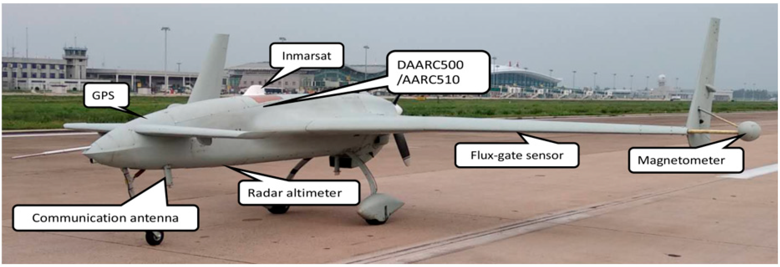
Figure 1. FUAV aeromagnetic system.
Minerals 13 00700 g001
Figure 2. MUH aeromagnetic system.
Minerals 13 00700 g002
Figure 3. Magnetic interference field of FUAV (a) before and (b) after the magnetic field weakening.
Minerals 13 00700 g003
Figure 4. Sketch map of the magnetic compensation track of the FUAV aeromagnetic system. The yellow points represent the track control points, the figures are the index number of these control points for inputting into the flight control system, and the red point represents the starting and ending positions of the CH-3 FUAV.
Minerals 13 00700 g004
Figure 5. Sketch map of magnetic compensation actions for (a) rolling, (b) pitching, and (c) yawing of the MUH aeromagnetic system. The x direction is the nose orientation of the MUH, α, β, and γ represent the angle of the rolling, pitching, and yawing action, respectively, and the curved arrow represents the MUH acts along the current axis.
Minerals 13 00700 g005
Figure 6. The magnetic compensation test of the FUAV aeromagnetic system. (a) Amplitude of X component (VecMagX), Y component (VecMagY), and Z component (VecMagZ) of the magnetic field; (b) comparison of the magnetic field before compensation (MagRaw) and after compensation (MagCopm).
Minerals 13 00700 g006
Figure 7. The magnetic compensation test of the MUH aeromagnetic system. (a) Amplitude of X component (VecMagX), Y component (VecMagY), and Z component (VecMagZ) of the magnetic field; (b) comparison of the magnetic field before compensation (MagRaw) and after compensation (MagCopm).
Minerals 13 00700 g007
Figure 8. The aeromagnetic survey in a tidal flat area in Jiangsu province in China. The blue rectangle represents the survey area, the black lines in the east–west direction represent the survey lines, and the black lines in the south–north direction represent the crosslines.
Minerals 13 00700 g008
Figure 9. Comparison of TMI contour maps after IGRF correction of the aeromagnetic survey between the (a) FUAV and (b) MUH aeromagnetic systems. Arrow A points to the magnetic anomalies that may be caused by the windmills.
Minerals 13 00700 g009
Table 1. The comparison of the main parameters between the FUAV and MUH aeromagnetic systems.
DescriptionFUAVMUH
Data typeTMI/horizontal gradientTMI
Year20132017
MagnetometerCS-3/CS-VLCS-VL
Compensation and collection system AARC51/AARC500/
AARC510/DAARC510
AARC51/AARC510
UAV platformCH-3 FUAVWH-110A MUH
Wingspan8 mHelicopter
Maximum takeoff weight640 kg110 kg
Takeoff and landing wayWheel autonomyVertical
Cruising speed170–200 km/h≤60 km/h
Maximum flight time10 h3 h
Control distanceRadio within 250 km/maritime satelliteRadio within 100 km
Night flightYesNo
Positioning systemDGPSDGPS
Maximum payload160 kg35 kg
Note: the parameters of the UAVs are provided by the aircraft manufacturers.
Table 2. Results of the magnetic compensation.
SystemUncoCompImprNormBias
FUAV0.545090.0142838.18538.94014.591
MUH0.397660.046908.47910.3833.059
Note: Unco represents the standard deviation of the uncompensated signal in units of [nT]. Comp represents the standard deviation of the compensated signal in units of nT. Impr represents the improvement ratio, Unco/Comp. Norm represents the vector norm of the solution and provides an indication of the degree of difficulty in obtaining the solution. Bias represents the difference between the mean values of Comp and Unco.
Disclaimer/Publisher’s Note: The statements, opinions and data contained in all publications are solely those of the individual author(s) and contributor(s) and not of MDPI and/or the editor(s). MDPI and/or the editor(s) disclaim responsibility for any injury to people or property resulting from any ideas, methods, instructions or products referred to in the content.