Abstract
Ferromanganese nodule nuclei are considered crucial to the formation and distribution of nodules. However, because it is difficult and time-consuming to study ferromanganese nodule nuclei, few studies have been performed, despite the large number of samples. Here, we analyzed the nuclei of 934 ferromanganese nodules from the abyssal seafloor around Minamitorishima Island (western North Pacific Ocean) using X-ray computed tomography (CT). Based on the CT number distribution (describing X-ray absorption in Hounsfield units, HU), we classified the nuclei as Type I (>1800 HU) or Type II (<1800 HU). Additionally, some Type I nuclei had characteristic conical shapes (Type I-C) distinct from the shapes of other nuclei (Type I-O). Based on the chemical compositions determined by microfocus X-ray fluorescence analyses of selected samples, we identified Type I-C, I-O, and II nuclei as fish teeth, hard rocks (volcanic rock, ironstone, or phosphorite), and sediments, respectively. These nucleus types were observed in sufficient quantities at all dive sites that we conclude them to be typical of nodule nuclei in the study area. Fish-tooth nuclei were the rarest at all sites, whereas sediment nuclei dominated at most sites, suggesting their significance for understanding the origin of ferromanganese nodules. Hard-rock nuclei dominated at only three sites and probably originated from seamounts.
1. Introduction
Ferromanganese nodules are spherical chemical deposits composed of iron and manganese oxides and hydroxides, and are widely distributed on the deep seafloor. Because they are enriched with economically critical metals such as nickel, copper, cobalt, and rare-earth elements, they may represent a potential resource for high-tech and green products [1]. Large nodule fields have been identified in various locations, such as the Clarion–Clipperton Zone (CCZ), Peru Basin, Penrhyn–Samoa basins, and Central Indian Ocean Basin [2]. Since the 1970s, the CCZ has attracted particular interest due to its vast dimensions, high spatial density of nodules, and high concentrations of copper and nickel [1,3]. In addition, a large field of ferromanganese nodules with high concentrations of cobalt, nickel, and copper was recently discovered in the Japanese Exclusive Economic Zone around Minamitorishima Island, in the western North Pacific Ocean [4,5].
Elucidating the geological/environmental factor(s) that control the distribution of ferromanganese nodules is important to exploration efforts for this critical metal resource. Because exploration of the deep seafloor is difficult and costly, efficiently constraining the locations of potential nodule fields requires a theoretical understanding of nodule formation. However, the factors that control the distribution of ferromanganese nodules remain poorly understood; most studies have focused on determining the conditions that promote the growth of ferromanganese oxides and hydroxides [6,7,8] rather than understanding nodule distributions [5,9].
Almost all ferromanganese nodules contain an identifiable nucleus upon which layers of ferromanganese oxide/hydroxide began to grow. The importance of these nuclei to nodule formation has been noted in previous studies [9,10,11,12]. In other words, without their nuclei, nodules would not form. Therefore, we consider that the origin(s) of nuclei is one of the most important factors controlling the formation and distribution of ferromanganese nodules. However, examining a nodule’s nucleus is challenging because it requires identifying the cross-section containing the nucleus and dividing it in half for examination; by extension, examination of numerous nodule nuclei has proven time-consuming, costly, and impractical. Therefore, despite their significance to our understanding of ferromanganese nodules, few studies have focused on ferromanganese nodule nuclei.
X-ray computed tomography (CT) provides an effective method for the non-destructive observation of ferromanganese nodule interiors [13,14,15] because it can be used to easily visualize any cross section of an object and is more efficient than physically splitting the nodules in half. This method also facilitates the analysis of multiple nodule samples. Here, we used X-ray CT to investigate 934 ferromanganese nodule samples collected from the seafloor around Minamitorishima Island. After identifying nuclei in CT images, we sectioned some samples for elemental analyses of the nuclei by microfocus X-ray fluorescence (μ-XRF).
2. Materials and Methods
2.1. Samples
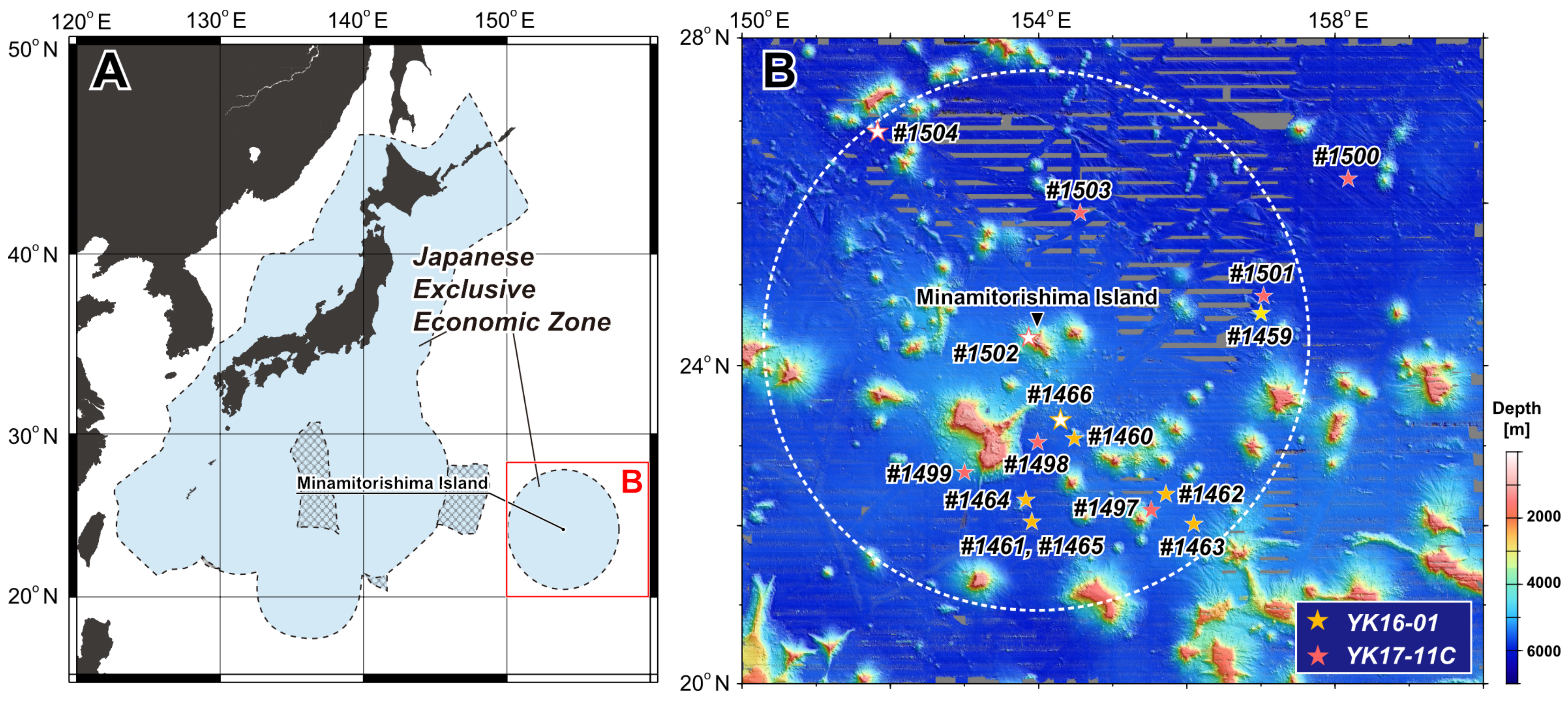
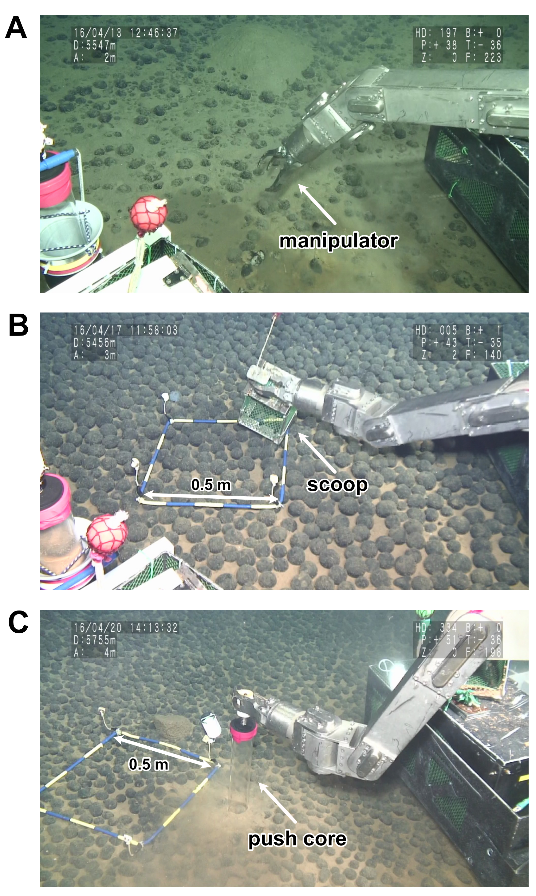
Ferromanganese nodules were collected during 16 dives using the manned submersible DSV Shinkai 6500 in the western North Pacific Ocean around Minamitorishima Island during the YK16-01 and YK17-11C cruises of R/V Yokosuka in 2016 and 2017, respectively (Figure 1). Nodules were sampled from 13 of the 16 dive sites using a manipulator, a scoop, or push cores. Some large samples were collected by targeted sampling using the manipulator arm of the Shinkai 6500 (Figure 2A), whereas most samples were obtained using a scoop to collect variously sized nodules without bias (Figure 2B). However, scoop sampling was not possible when nodules were connected stuck in the sediment. Push cores were used to collect nodules along with sediment samples (Figure 2C). Nodules sampled using push cores were kept in the same vertical orientation as on the seabed until their onboard recovery. The location, water depth, and sampling method employed at each site are listed in Table 1, alongside the number of nodule samples collected.
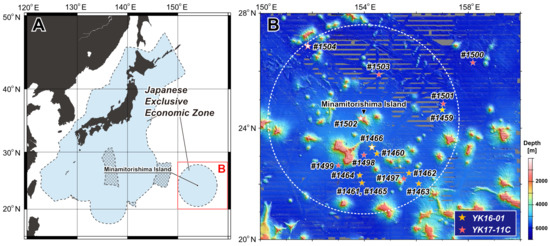
Figure 1.
(A) Location and (B) bathymetric maps of the study area. Hatched areas in (A) represent the extended continental shelves of Japan. Star symbols in (B) are DSV Shinkai 6500 dive sites during cruises YK16-01 and YK17-11C of R/V Yokosuka. Colored (yellow and orange) and white stars indicate sites where ferromanganese nodules were and were not sampled, respectively. The dashed white circle in (B) represents the Japanese Exclusive Economic Zone, and areas in which no bathymetric data are available are shown in gray.
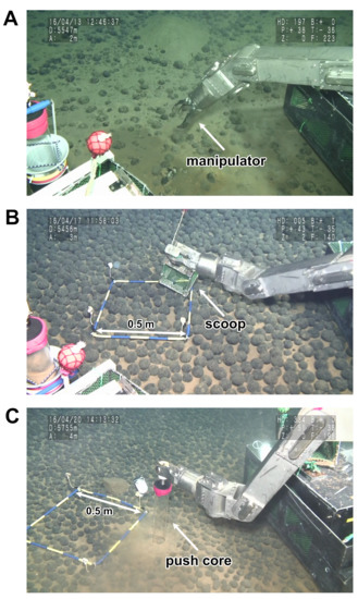
Figure 2.
Representative photographs of ferromanganese nodule sampling using (A) the DSV Shinkai 6500 manipulator arm, (B) a scoop, and (C) a push core.

Table 1.
Sampling locations, sampling methods, and the number of nodules sampled at each site during cruises YK16-01 and YK17-11C.
2.2. Analytical Method
X-ray CT: To observe nodule nuclei, we performed X-ray CT analysis of 934 samples using a Lightspeed medical X-ray CT scanner (GE Healthcare, Chicago, IL, USA) for samples from dives 6K#1459 to 1464 (cruise YK16-01) and an Aquilion PRIME/Focus Edition X-ray scanner (Canon Medical System Corp., Otawara, Tochigi, Japan) for samples from dives 6K#1465 (cruise YK16-01), 6K#1497 to 1501, and 6K#1503 (cruise YK17-11C) at the Center for Advanced Marine Core Research, Kochi University (Kochi, Japan). Both scanners were operated at 120 kV and 100 mA. CT analyses using the Lightspeed medical X-ray scanner were performed with a slice width of 0.625 mm, image resolution of 512 × 512 pixels, pixel sizes of 0.1875 × 0.1875 mm2 to 0.334 × 0.334 mm2 depending on the sample size, and 0.5 s of X-ray exposure time per slice. The analyses carried out with the Aquilion PRIME/Focus Edition X-ray scanner were performed with a slice width of 0.5 mm, image resolution of 512 × 512 pixels, pixel sizes of 0.128 × 0.128 mm2 to 0.618 × 0.618 mm2 depending on the sample size, and 0.5 s of X-ray exposure time per slice.
The signal at each point in a CT image is the CT number, which describes the X-ray absorption of the material within that voxel (i.e., volumetric pixel) in Hounsfield units (HU) as follows:
where µ and µw are the linear X-ray absorption coefficients of the sample and pure water, respectively. Both CT scanners were calibrated to yield CT number of 0 HU for pure water and −1000 HU for air. The CT number of a material in any voxel depends on its density and chemical composition. The analytical results were output to the Digital Imaging and Communications in Medicine (DICOM) file format using the instrument′s operation program. Details on the principles of X-ray CT scanning are available elsewhere [16,17].
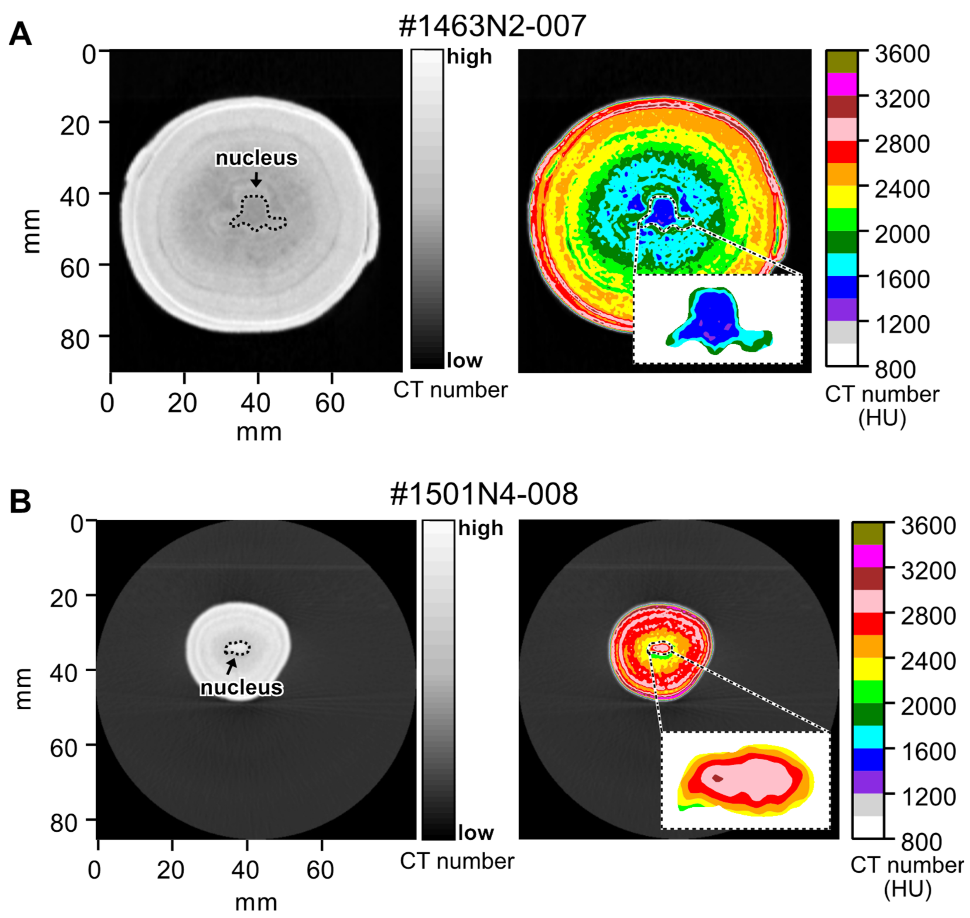
The DICOM files were visualized as CT images and contour plots in Python. In the contour plots, voxels are colored according to their CT number in increments of 200 HU. From these representations, the CT numbers corresponding to nuclei were determined in the following two steps: (1) nuclei were identified and outlined in the CT images based on their distinct CT numbers compared to the surrounding ferromanganese oxide layers, i.e., from the continuous CT number spectrum (left in Figure 3); and (2) the specific CT number of a nucleus was determined as the dominant CT number within the same area of the associated contour plot (right in Figure 3). In the examples of Figure 3, the nuclei are characterized by CT numbers in the range 1400–1600 HU (blue, Figure 3A) and 2800–3000 HU (pink, Figure 3B).
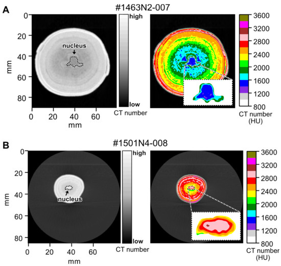
Figure 3.
X-ray CT images (left) and CT number contour plots (right) of representative nuclei in ferromanganese nodules (A) #1463N2-007 and (B) #1501N4-008.
Elemental mapping by μ-XRF: To further characterize the nuclei and their constituent materials, some samples were cut into half for elemental mapping by µ-XRF. Cutting planes were determined based on the 3D X-ray CT images so that the nuclei would appear within the cut sections. Then, the exposed nuclei were analyzed by µ-XRF spectroscopy using a Rh X-ray tube at Kyoto University (XGT-7000V; Horiba, Kyoto, Japan) following the method described by [18].
We determined the intensities of Al, Ca, Cr, Fe, K, Mg, Mn, Ni, P, Si, and Ti. Multiple measurements were made using a tube voltage of 50 kV, a tube current of 0.9 A, and an X-ray beam diameter of 100 μm in vacuo. The samples were scanned in approximately 90–178 μm intervals (pixel size) depending on the dimension of the mapping area. Elemental intensities were determined from the cumulative intensity of the analysis, with a total analysis time of 76–543 ms per pixel.
3. Results and Discussion
3.1. Classification of the Ferromanganese Nodule Nuclei
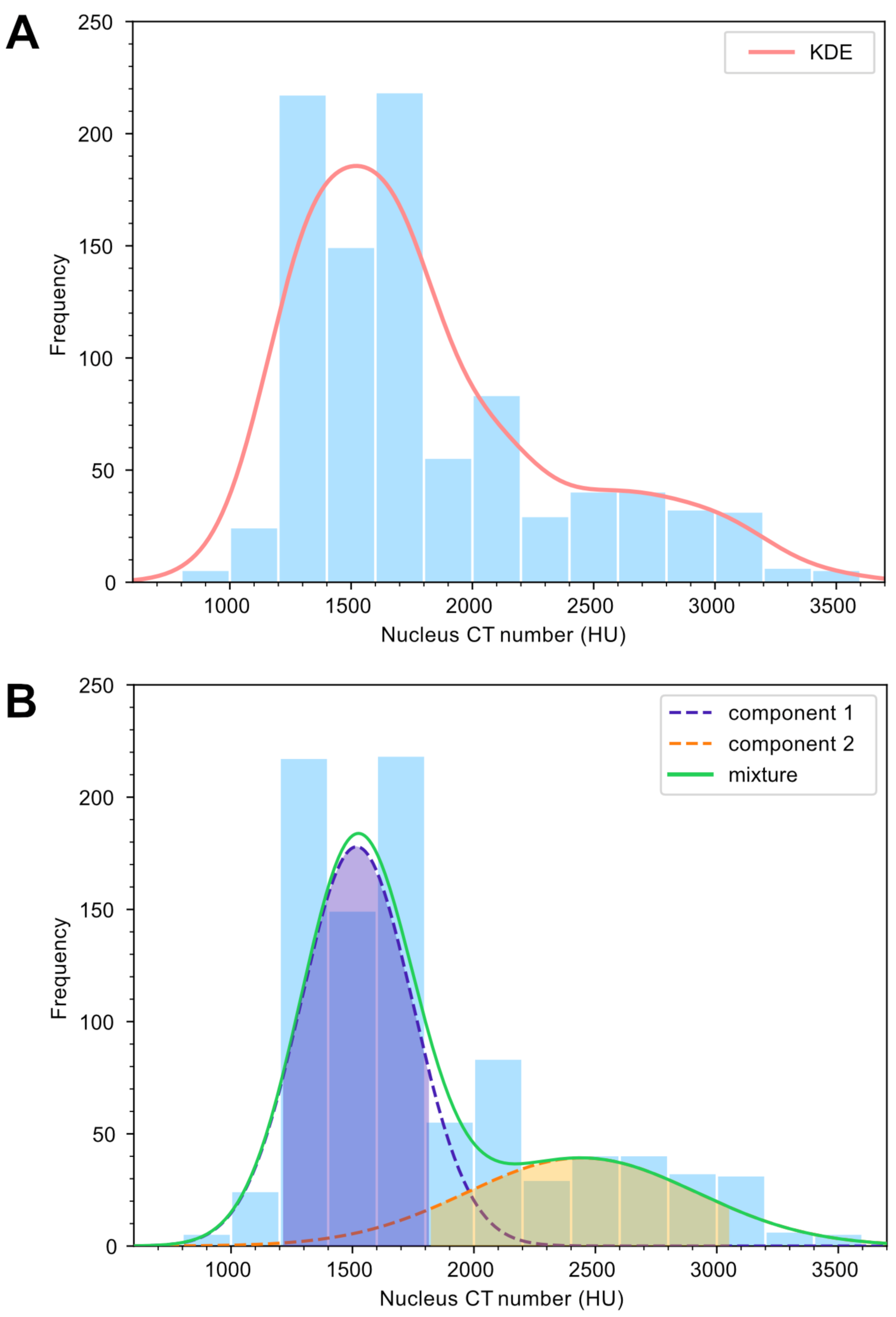
Various materials have been suggested as nodule nuclei in previous studies, including volcanic rock fragments, pumice, both consolidated and soft seafloor sediments, and shark teeth [19,20,21]. Consistently, we observed a wide distribution of nuclei CT numbers (Figure 4A). Because the CT number depends on density and chemical composition, materials with essentially the same density and composition show identical CT numbers. Thus, the multi-modal distribution of CT numbers in Figure 4A suggests that various materials constitute nuclei with different CT numbers.
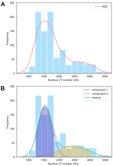
Figure 4.
(A) The distribution of nucleus CT numbers from ferromanganese nodules collected at all dive sites and the corresponding kernel density estimate (KDE). (B) A Gaussian mixture model (GMM) fitted to the CT number histogram. The GMM components and the overall mixture are shown in different colors and overlaid on the histogram. Shaded areas represent 1.31 standard deviations on either side of the mean of each component (i.e., the central 81% of the distribution of each component), which we used to delimit the boundary between the two components (see text for details).
A notable proportion of our samples had CT numbers lower than 1800 HU, particularly in the range 1200–1800 HU, whereas many had broadly higher CT numbers in the range 1800–3600 HU (Figure 4A). Kernel density estimation of the histogram showed two peaks in the CT number distribution (Figure 4A), and Gaussian mixture modelling reasonably explained the histogram as the mixture of two Gaussian components (Figure 4B). Considering the central 81% of each component′s distribution (1.31 standard deviations; shaded in Figure 4B), these two areas touch at approximately 1800 HU (1821 HU). Therefore, we consider that nuclei with CT numbers above and below 1800 HU are essentially different materials; accordingly, we classified nuclei with CT numbers above and below 1800 HU as Type I and Type II, respectively.
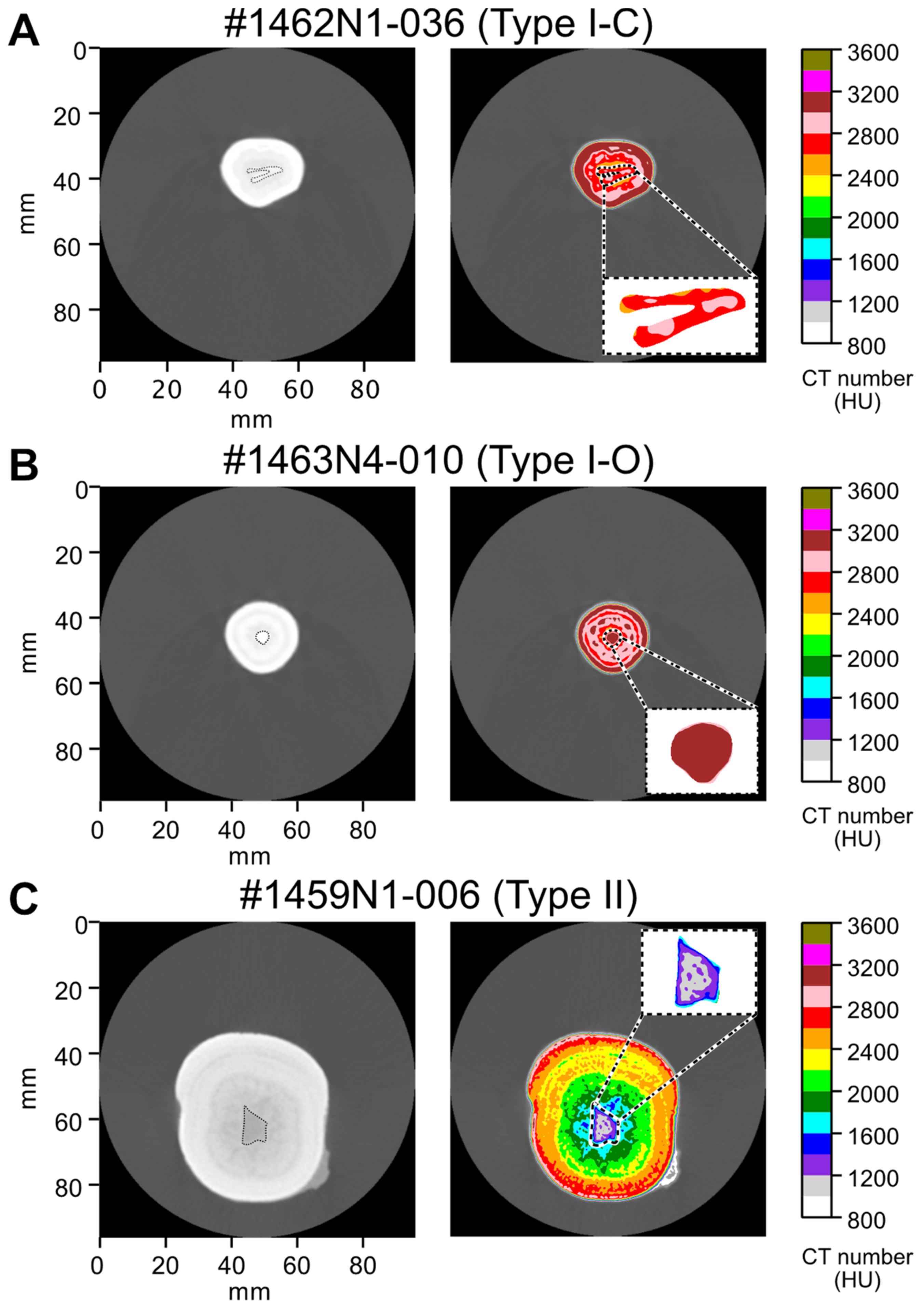
We noted that some Type I nuclei showed a characteristic conical morphology (i.e., V-shaped in cross section; Figure 5A). Therefore, we further subdivided Type I nuclei into the following two groups: Type I-C (conical) and Type I-O (others). Type I-C samples accounted for 12.8% of the Type I nuclei. Types I-O and II nuclei did not show any characteristic shape (Figure 5B,C).
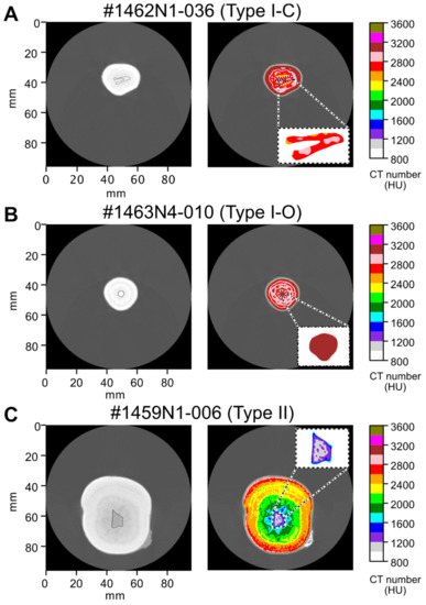
Figure 5.
X-ray CT images (left) and CT number contour plots (right) of representative nuclei classified as (A) Type I-C, (B) Type I-O, and (C) Type II.
3.2. Identification of the Nuclei of Each Type
For each type of nucleus, representative samples with sufficiently large nuclei were analyzed by µ-XRF elemental mapping, and the materials comprising the nuclei were determined based on their chemical characteristics in the µ-XRF elemental maps and any other identifying features. We performed µ-XRF analyses of one Type I-C, three Type I-O, and three Type II nuclei.
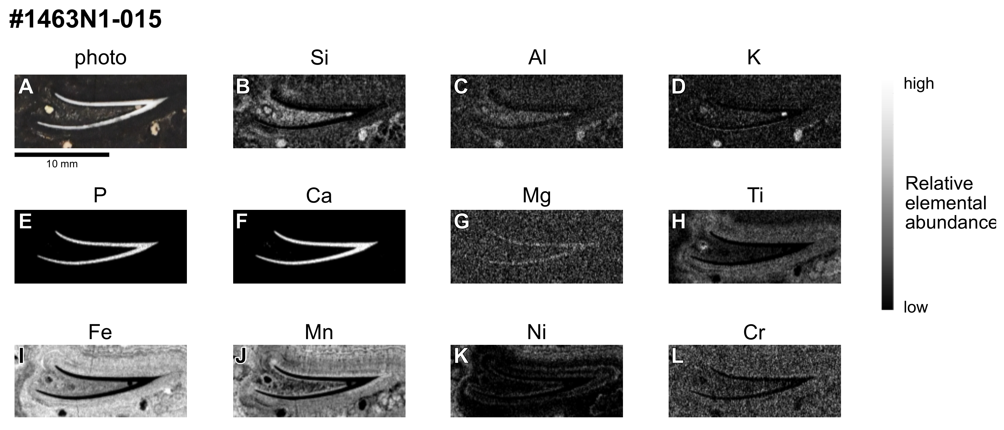
Type I-C nuclei are V-shaped and white in color (Figure 6A). In µ-XRF elemental maps, only P and Ca are concentrated in the nuclei (Figure 6E,F). These results clearly suggest that these nuclei are fish teeth. Indeed, biogenic calcium phosphate (BCP), mainly comprising P and Ca and known to include fish teeth, is ubiquitously found in seafloor sediments (e.g., [22,23]).
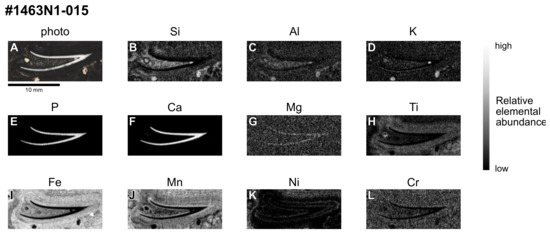
Figure 6.
(A) Photograph and (B–L) μ-XRF elemental maps of the cross section of a representative Type I-C nucleus (#1463N1-015) interpreted to be a fish tooth.
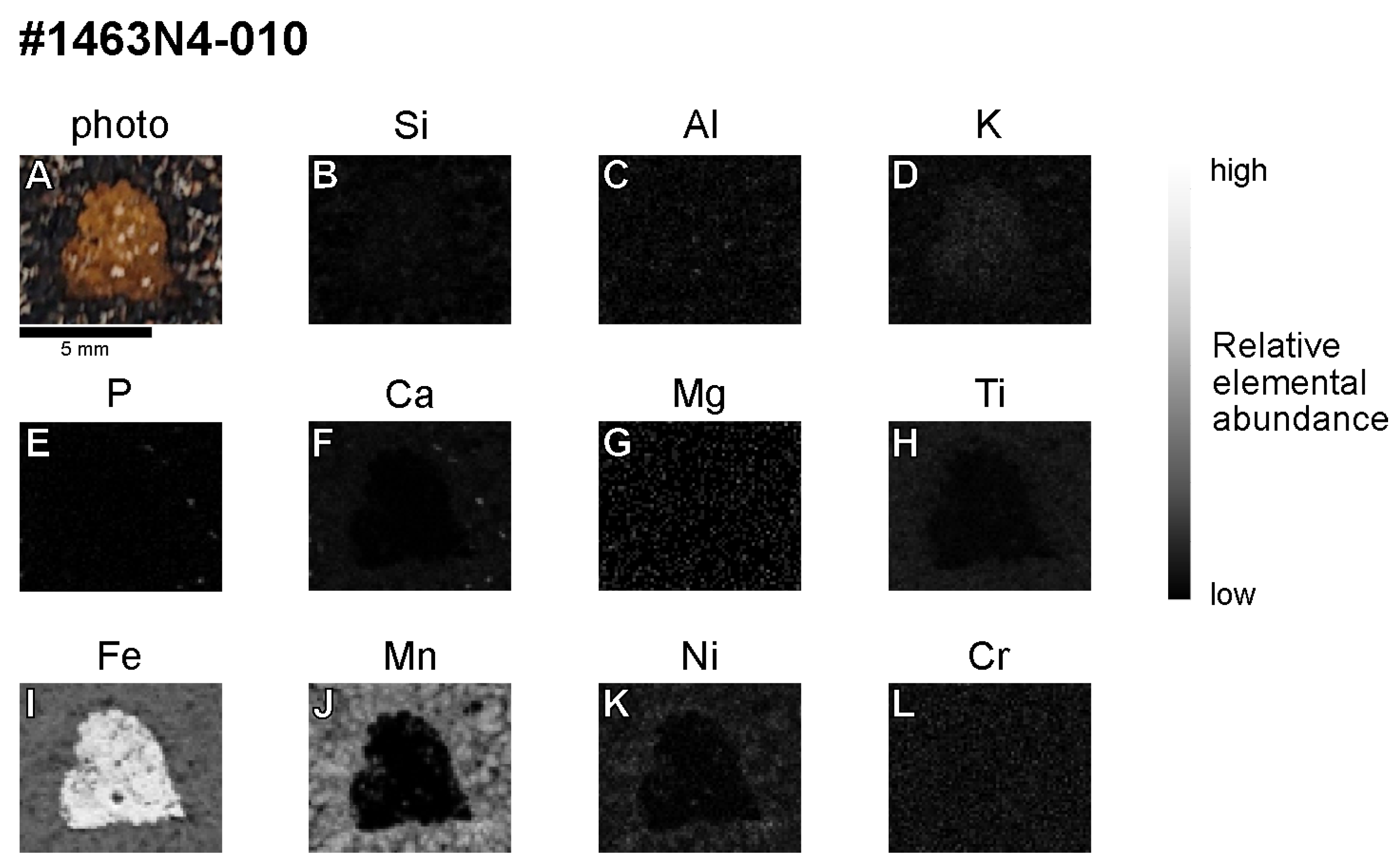
The three Type I-O nuclei were markedly different. The first is reddish-brown in color (Figure 7A) and is only enriched with Fe (Figure 7I). Previous studies have reported Fe-rich hydrothermal materials of a similar brown color, known as ironstones, that originated from pelagic seamounts [24,25], and we accordingly interpret this nucleus to be ironstone.
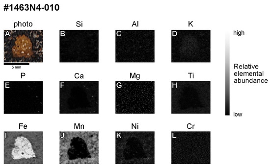
Figure 7.
(A) Photograph and (B–L) µ-XRF elemental maps of the cross section of a representative Type I-O nucleus (#1463N4-010) interpreted to be an ironstone.
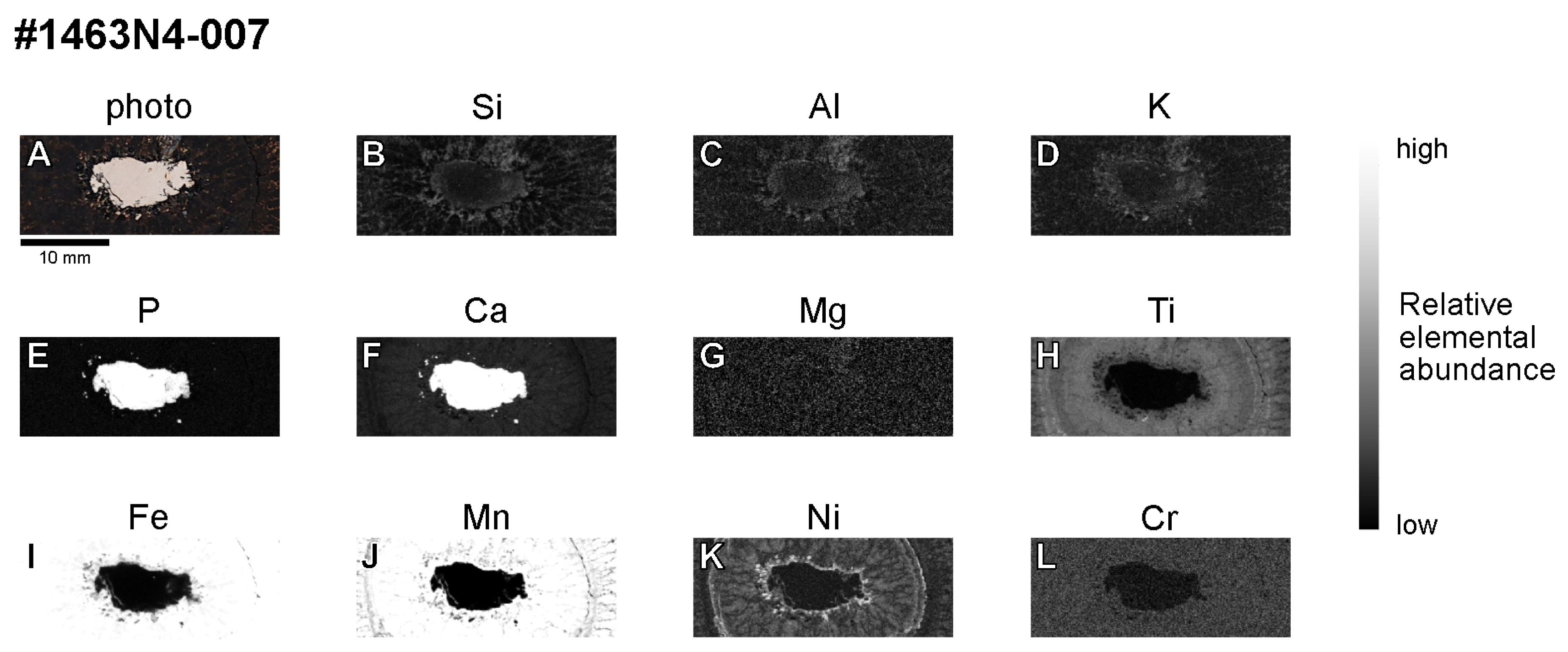
The second Type I-O nucleus is white to yellow in color (Figure 8A) and rich in P and Ca (Figure 8E,F). Although this chemical characteristic might suggest calcium phosphate and/or BCP, this particular nucleus shows massive texture and is unlike the tooth or bone fragments of marine vertebrates. Thus, we interpret this nucleus not to be BCP, but a phosphorite, known to form when carbonate rocks on seamounts are phosphatized by P-rich seawater [26,27].
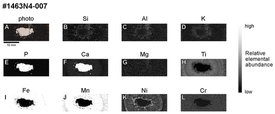
Figure 8.
(A) Photograph and (B–L) µ-XRF elemental maps of the cross section of a representative Type I-O nucleus (#1463N4-007) interpreted to be a phosphorite.
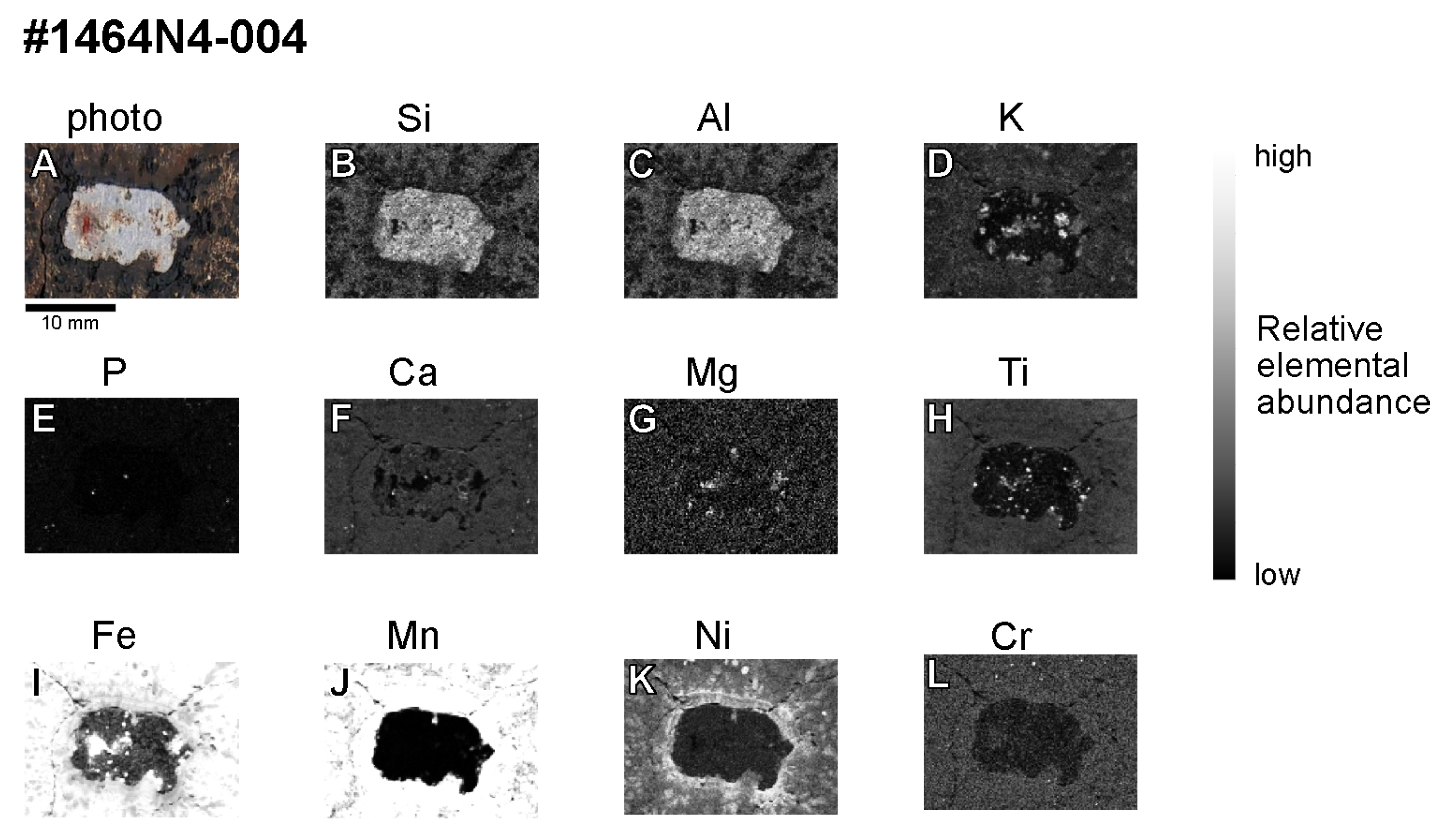
The third Type I-O nucleus is generally gray in color (Figure 9A), is rich in Si and Al, and locally rich in K, Mg, Ti, and Fe (Figure 9). These elements are consistent with the main components of igneous rocks that form seamounts (e.g., [28]). Therefore, according to its gray color, we interpret this nucleus to be an igneous rock.
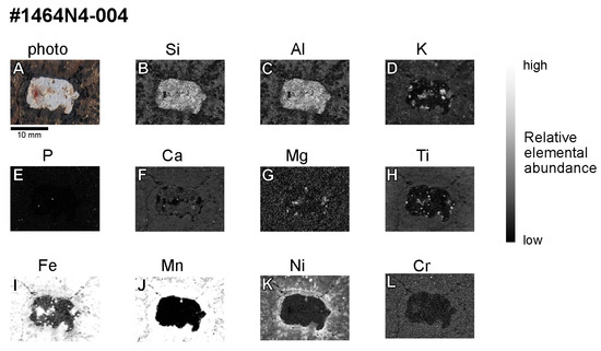
Figure 9.
(A) Photograph and (B–L) µ-XRF elemental maps of the cross section of a representative Type I-O nucleus (#1464N4-004) interpreted to be an igneous rock.
Although the Type I-O nuclei identified in this study are of different origins, they are all hard rocks that occur on seamounts [24,27,28]. This conclusion is consistent with their high CT numbers that are indicative of their high densities. The CT numbers of the ironstone (#1463N4-010), phosphorite (#1463N4-007), and igneous rock (#1464N4-004) nuclei were 3000–3200 HU, 2800–3000 HU, and 2000–2200 HU, respectively. These CT numbers correspond to the order of density of constituent minerals. From these results, the wide range of CT numbers above 1800 HU reflects the presence of several rock types with different CT numbers.
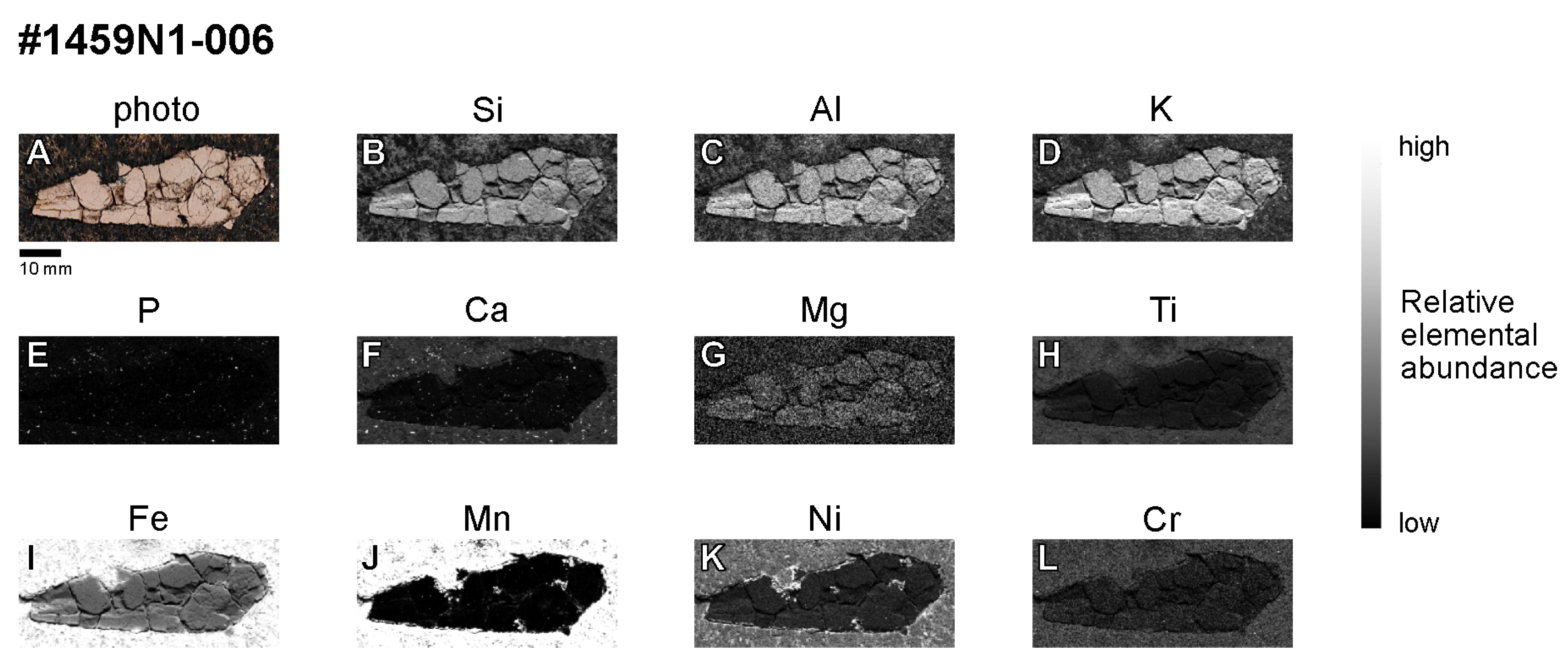
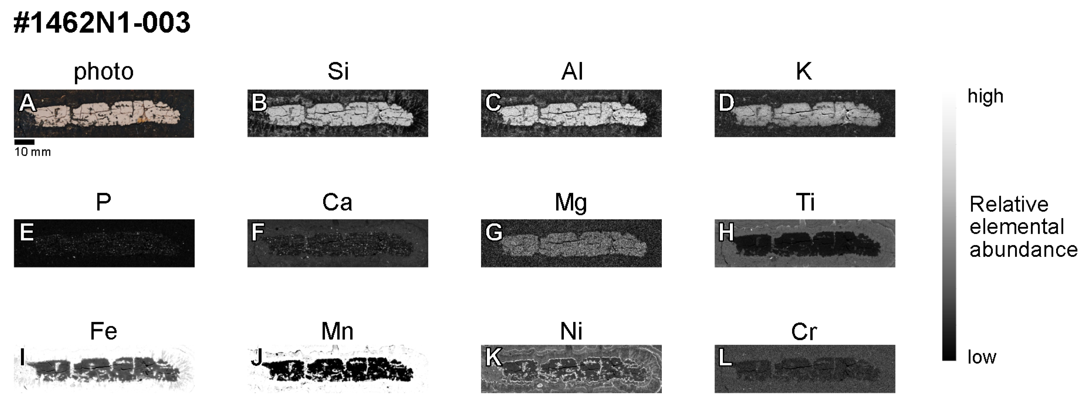
All three Type II samples were light brown in color and consistently rich in Si, Al, and K (Figure 10 and Figure 11). These characteristics are similar to pelagic clays composed of aluminosilicates [29], suggesting that Type II nuclei are solidified pelagic clay. We note that nucleus #1462N1-003 shows local concentrations of P and Ca (Figure 11E,F). Small BCP grains constitute an important host of rare-earth elements and Y (REY) in deep-sea sediments [30], and a certain type of sediment known to concentrate BCP, and thus REY, is called REY-rich mud [31,32]. Therefore, we interpret this nucleus to be REY-rich mud containing a substantial amount of BCP, which is widely distributed around Minamitorishima Island [30,33,34].
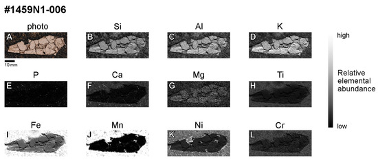
Figure 10.
(A) Photograph and (B–L) µ-XRF elemental maps of the cross section of a representative Type II nucleus (#1459N1-006) interpreted to be pelagic clay.
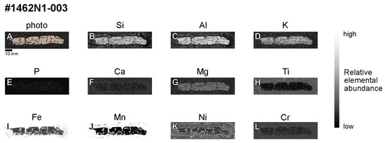
Figure 11.
(A) Photograph and (B–L) µ-XRF elemental maps of the cross section of a representative Type II nucleus (#1462N1-003) interpreted to be REY-rich mud containing a substantial amount of BCP.
3.3. Nuclei Proportions
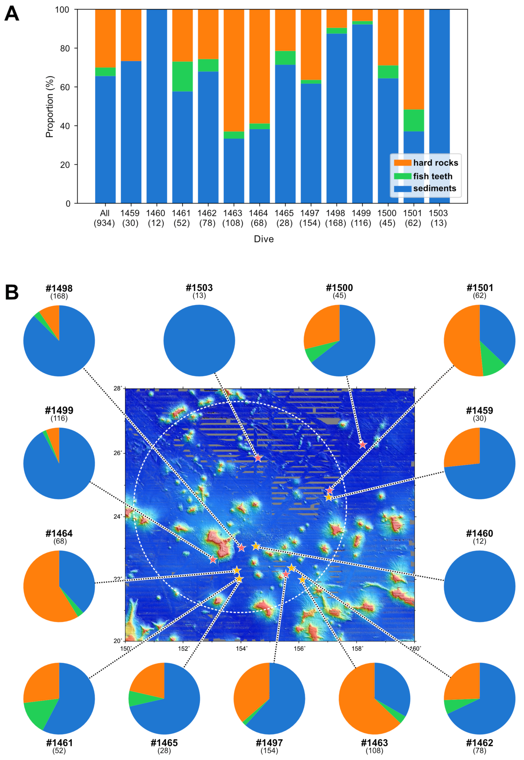
As described above, we identified three materials (fish teeth, hard rocks, and sediments) as ferromanganese nodule nuclei around Minamitorishima Island. Figure 12A shows the observed proportions of each nucleus type at each dive site. All three nucleus types were observed at all dive sites, except 6K#1459, 6K#1460, and 6K#1503 (Figure 12A), indicating that these materials are commonly supplied to the seafloor over a wide area around Minamitorishima Island.
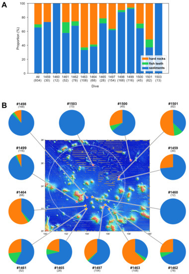
Figure 12.
(A) Stacked column charts indicating the relative amounts of the three nodule nucleus types observed overall (left column) and at each dive site (other columns). Numbers in brackets under the dive sites indicate the total number of nodules collected at each site. (B) Pie charts of the column data from (A) at each dive site are linked to the site locations to indicate the relative geographical distributions of the nodule nucleus types. In (B), areas in which no bathymetric data are available are shown in gray.
It is unclear whether the observed proportions of the three materials accurately reflect their true proportions, especially at sites where few samples (<50) were obtained. Nonetheless, fish-tooth nuclei were observed at all except three sites, but in small proportions, consistent with the reported ubiquity yet infrequency of teeth and bone fragments on the deep seafloor (e.g., [23,35]). Notably, these nuclei were not observed at the three sites where we sampled the fewest nodules, and their observed absence at those sites may represent a sampling bias. Therefore, we interpret fish teeth to be ubiquitous but minor constituents of nodule nuclei, and thus only a minor influence on the distribution of ferromanganese nodules in the study area.
In contrast, hard-rock and sediment nuclei were major components of ferromanganese nodule nuclei (>30 samples observed) at all sites except 6K#1460 and 6K#1503, where we observed exclusively sediment nuclei. Hard-rock nuclei were the dominant nuclei type at only three sites (6K#1463, 6K#1464, 6K#1501), whereas sediment nuclei dominated at all other sites (Figure 12A).
Igneous rocks, ironstones, and phosphorites that we observed to compose hard-rock nuclei are known to be present on seamounts [24,27,28]. Because no hard rocks have been reported in sediment cores recovered from the study area [33,34,36] and no signs of geologically recent major volcanic activity have been observed in the surrounding areas, we infer that these nuclei were supplied directly to the seafloor from their seamounts of origin after volcanic and hydrothermal activity had subsided. We note that we observed hard-rock nuclei in nodules collected far from seamounts (e.g., sites 6K#1461, 6K#1465; Figure 12B). Although the specific process of transporting these nuclei to such sites is beyond the scope of this study, we speculate that such rock fragments can be transported up to ~50 km from their source seamounts. We note that the proportion of hard-rock nuclei may not necessarily correlate with distance to the nearest seamount because the amount of hard rocks supplied to a given site depends on which seamount collapsed and on which scale a collapse of the seamount occurred. Recently, based on geophysical surveys, it was suggested that seamount collapses may supply the debris that forms ferromanganese nodule nuclei [37]; accordingly, our findings suggest that some, but not all, nodule nuclei may derive from seamount collapses.
Because sediment nuclei are the most common nodule nuclei around Minamitorishima Island, determining their origins is of paramount importance in elucidating the factors that control the ferromanganese nodule distribution there. Sediments are ubiquitous on both seamounts and seabeds, but our data do not allow us to determine the seamount vs. seabed provenance of these nuclei. Therefore, a more detailed characterization of sediment (i.e., Type II) nuclei using µ-XRF is an important goal for future studies, and X-ray CT analysis will help identify target nuclei.
4. Conclusions
We performed X-ray CT analysis of the nuclei of 934 ferromanganese nodules collected from the seafloor around Minamitorishima Island in the western North Pacific Ocean. Based on those results, we performed µ-XRF elemental mapping of selected samples. We drew the following conclusions.
- We identified two groups (Types I and II) of nodule nuclei based on their CT numbers. We further subdivided Type I into Type I-C (conical) and Type I-O (other) based on nucleus shape.
- Based on macroscopic observations and elemental maps, we identified Type I-C, Type I-O, and Type II nuclei as fish teeth, hard rocks (igneous rocks, ironstones, or phosphorites), and sediments (pelagic clays or REY-rich muds containing substantial amounts of BCP), respectively.
- Fish-tooth (Type I-C) nuclei were observed at all sites where a sufficient number of nodules was collected. Fish teeth, therefore, represent a ubiquitous but minor nodule nucleus type in the study area.
- Hard-rock (Type I-O) nuclei represented a major proportion of nodule nuclei at most sites, but were most often subordinate to sediment nuclei. We interpret that hard-rock nuclei were supplied from seamounts, consistent with recent geophysical data [36].
- Sediment (Type II) nuclei dominated nodule nuclei overall, but we could not determine their seamount vs. seabed provenance. Therefore, to better understand the ferromanganese nodule distribution in the study area, it is essential to determine the provenance of the sediments in Type II nuclei.
Supplementary Materials
The following supporting information can be downloaded at: https://www.mdpi.com/article/10.3390/min13060710/s1, Table S1: CT numbers and shapes of ferromanganese nodule nuclei collected during cruises YK16-01 and YK17-11C.
Author Contributions
Conceptualization, K.N.; methodology, K.N., D.T. and R.S.; formal analysis, D.T., R.S. and K.N.; investigation, D.T., R.S. and K.N.; resources, K.N., K.Y. and Y.K.; data curation, D.T. and K.N.; writing—original draft preparation, D.T., K.N. and R.S.; writing—review and editing, all authors; visualization, D.T., R.S. and K.N.; supervision, K.N. and Y.K.; project administration, K.N.; funding acquisition, K.N., S.M. and Y.K. All authors have read and agreed to the published version of the manuscript.
Funding
This research was funded by the cross-ministerial Strategic Innovation Promotion Program (SIP) “Innovative Technology for Exploration of Deep-Sea Resources” (Lead agency: JAMSTEC) and Japan Society for the Promotion of Science (JSPS) through the Grant-in-Aid Scientific Research (S) No. 15H05771, (A) No. 17H01361, and (A) No. 21H04667.
Data Availability Statement
Data are shown in all figures and tables of the main text and in the Supplementary Materials. Raw data of X-ray CT can be provided from the corresponding author upon request.
Acknowledgments
We thank the DSV Shinkai 6500 operation team and the crew of the R/V Yokosuka for their skillful support during the YK16-01 and YK17-11C cruises. The research cruises were conducted in the SIP of Japan. We are also grateful to N. Ahagon, R. Yamaoka, T. Yabuki, and K. Yoshida for their assistance with the X-ray CT scanning, and T. Kogiso for his assistance with the µ-XRF analysis.
Conflicts of Interest
The authors declare no conflict of interest. The funders had no role in the design of the study; in the collection, analyses, or interpretation of data; in the writing of the manuscript, or in the decision to publish the results.
References
- Hein, J.R.; Mizell, K.; Koschinsky, A.; Conrad, T.A. Deep-Ocean Mineral Deposits as a Source of Critical Metals for High- and Green-Technology Applications: Comparison with Land-Based Resources. Ore Geol. Rev. 2013, 51, 1–14. [Google Scholar] [CrossRef]
- Hein, J.R.; Koschinsky, A.; Kuhn, T. Deep-Ocean Polymetallic Nodules as a Resource for Critical Materials. Nat. Rev. Earth Environ. 2020, 1, 158–169. [Google Scholar] [CrossRef]
- Halbach, P.; Friedrich, G.; von Stackelberg, U. The Manganese Nodule Belt of the Pacific Ocean: Geological Environment, Nodule Formation and Mining Aspects; F. Enke: Stuttgart, Germany, 1988. [Google Scholar]
- Machida, S.; Fujinaga, K.; Ishii, T.; Nakamura, K.; Hirano, N.; Kato, Y. Geology and Geochemistry of Ferromanganese Nodules in the Japanese Exclusive Economic Zone around Minamitorishima Island. Geochem. J. 2016, 50, 539–555. [Google Scholar] [CrossRef]
- Machida, S.; Sato, T.; Yasukawa, K.; Nakamura, K.; Iijima, K.; Nozaki, T.; Kato, Y. Visualisation Method for the Broad Distribution of Seafloor Ferromanganese Deposits. Mar. Georesour. Geotechnol. 2021, 39, 267–279. [Google Scholar] [CrossRef]
- Josso, P.; Pelleter, E.; Pourret, O.; Fouquet, Y.; Etoubleau, J.; Cheron, S.; Bollinger, C. A New Discrimination Scheme for Oceanic Ferromanganese Deposits Using High Field Strength and Rare Earth Elements. Ore Geol. Rev. 2017, 87, 3–15. [Google Scholar] [CrossRef]
- Kashiwabara, T.; Takahashi, Y.; Tanimizu, M.; Usui, A. Molecular-Scale Mechanisms of Distribution and Isotopic Fractionation of Molybdenum between Seawater and Ferromanganese Oxides. Geochim. Cosmochim. Acta 2011, 75, 5762–5784. [Google Scholar] [CrossRef]
- Koschinsky, A.; Hein, J.R. Marine Ferromanganese Encrustations: Archives of Changing Oceans. Elements 2017, 13, 177–182. [Google Scholar] [CrossRef]
- Machida, S.; Shimomura, R.; Nakamura, K.; Kogiso, T.; Kato, Y. Intermittent Beginning to the Formation of Hydrogenous Ferromanganese Nodules in the Vast Field: Insights from Multi-Element Chemostratigraphy Using Microfocus X-ray Fluorescence. Minerals 2021, 11, 1246. [Google Scholar] [CrossRef]
- González, F.J.; Somoza, L.; Lunar, R.; Martínez-Frías, J.; Martín Rubí, J.A.; Torres, T.; Ortiz, J.E.; Díaz del Río, V.; Pinheiro, L.M.; Magalhães, V.H. Hydrocarbon-Derived Ferromanganese Nodules in Carbonate-Mud Mounds from the Gulf of Cadiz: Mud-Breccia Sediments and Clasts as Nucleation Sites. Mar. Geol. 2009, 261, 64–81. [Google Scholar] [CrossRef]
- Hein, J.R.; Spinardi, F.; Okamoto, N.; Mizell, K.; Thorburn, D.; Tawake, A. Critical Metals in Manganese Nodules from the Cook Islands EEZ, Abundances and Distributions. Ore Geol. Rev. 2015, 68, 97–116. [Google Scholar] [CrossRef]
- Mukhopadhyay, R.; Ghosh, A.K. Dynamics of Formation of Ferromanganese Nodules in the Indian Ocean. J. Asian Earth Sci. 2010, 37, 394–398. [Google Scholar] [CrossRef]
- Azami, K.; Yasukawa, K.; Kato, Y. Geochemistry of Ferromanganese Nodules in the Soil of Okinawa Island, Japan: Paleoclimatic Implications and Discrimination Scheme of the Nodule Origins. J. Asian Earth Sci. X 2022, 8, 100127. [Google Scholar] [CrossRef]
- Benites, M.; Millo, C.; Hein, J.; Nath, B.N.; Murton, B.; Galante, D.; Jovane, L. Integrated Geochemical and Morphological Data Provide Insights into the Genesis of Ferromanganese Nodules. Minerals 2018, 8, 488. [Google Scholar] [CrossRef]
- Nakamura, K.; Terauchi, D.; Shimomura, R.; Machida, S.; Yasukawa, K.; Fujinaga, K.; Kato, Y. Three-Dimensional Structural Analysis of Ferromanganese Nodules from the Western North Pacific Ocean Using X-ray Computed Tomography. Minerals 2021, 11, 1100. [Google Scholar] [CrossRef]
- Keller, A. High Resolution, Non-Destructive Measurement and Characterization of Fracture Apertures. Int. J. Rock Mech. Min. Sci. 1998, 35, 1037–1050. [Google Scholar] [CrossRef]
- Ohtani, T.; Nakashima, Y.; Muraoka, H. Three-Dimensional Miarolitic Cavity Distribution in the Kakkonda Granite from Borehole WD-1a Using X-Ray Computerized Tomography. Eng. Geol. 2000, 56, 1–9. [Google Scholar] [CrossRef]
- Machida, S.; Nakamura, K.; Kogiso, T.; Shimomura, R.; Horinouchi, K.; Okino, K.; Kato, Y. Fine-Scale Chemostratigraphy of Cross-Sectioned Hydrogenous Ferromanganese Nodules from the Western North Pacific. Isl. Arc 2021, 30, e12395. [Google Scholar] [CrossRef]
- Sarkar, C.; Iyer, S.D.; Hazra, S. Inter-Relationship between Nuclei and Gross Characteristics of Manganese Nodules, Central Indian Ocean Basin. Mar. Georesour. Geotechnol. 2008, 26, 259–289. [Google Scholar] [CrossRef]
- Vineesh, T.C.; Nagender Nath, B.; Banerjee, R.; Jaisankar, S.; Lekshmi, V. Manganese Nodule Morphology as Indicators for Oceanic Processes in the Central Indian Basin. Int. Geol. Rev. 2009, 51, 27–44. [Google Scholar] [CrossRef]
- Park, K.; Jung, J.; Park, J.; Ko, Y.; Lee, Y.; Yang, K. Geochemical-Mineralogical Analysis of Ferromanganese Oxide Precipitated on Porifera in the Magellan Seamount, Western Pacific. Front. Mar. Sci. 2023, 9. [Google Scholar] [CrossRef]
- Maisch, H.M.; Becker, M.A.; Chamberlain, J.A. Macroborings in Otodus Megalodon and Otodus Chubutensis Shark Teeth from the Submerged Shelf of Onslow Bay, North Carolina, USA: Implications for Processes of Lag Deposit Formation. Ichnos 2020, 27, 122–141. [Google Scholar] [CrossRef]
- Toyoda, K.; Tokonami, M. Diffusion of Rare-Earth Elements in Fish Teeth from Deep-Sea Sediments. Nature 1990, 345, 607–609. [Google Scholar] [CrossRef]
- Hein, J.R.; Hsueh-Wen, Y.; Gunn, S.H.; Gibbs, A.E.; Chung-ho, W. Composition and Origin of Hydrothermal Ironstones from Central Pacific Seamounts. Geochim. Cosmochim. Acta 1994, 58, 179–189. [Google Scholar] [CrossRef]
- Benites, M.; Hein, J.R.; Mizell, K.; Farley, K.A.; Treffkorn, J.; Jovane, L. Geochemical Insights into Formation of Enigmatic Ironstones from Rio Grande Rise, South Atlantic Ocean. Mar. Geol. 2022, 444, 106716. [Google Scholar] [CrossRef]
- Bau, M.; Koschinsky, A.; Dulski, P.; Hein, J.R. Comparison of the Partitioning Behaviours of Yttrium, Rare Earth Elements, and Titanium between Hydrogenetic Marine Ferromanganese Crusts and Seawater. Geochim. Cosmochim. Acta 1996, 60, 1709–1725. [Google Scholar] [CrossRef]
- Hein, J.R.; Yeh, H.-W.; Gunn, S.H.; Sliter, W.V.; Benninger, L.M.; Wang, C.-H. Two Major Cenozoic Episodes of Phosphogenesis Recorded in Equatorial Pacific Seamount Deposits. Paleoceanography 1993, 8, 293–311. [Google Scholar] [CrossRef]
- Humphreys, E.R.; Niu, Y. On the Composition of Ocean Island Basalts (OIB): The Effects of Lithospheric Thickness Variation and Mantle Metasomatism. Lithos 2009, 112, 118–136. [Google Scholar] [CrossRef]
- Yasukawa, K.; Ohta, J.; Miyazaki, T.; Vaglarov, B.S.; Chang, Q.; Ueki, K.; Toyama, C.; Kimura, J.-I.; Tanaka, E.; Nakamura, K.; et al. Statistic and Isotopic Characterization of Deep-Sea Sediments in the Western North Pacific Ocean: Implications for Genesis of the Sediment Extremely Enriched in Rare Earth Elements. Geochem. Geophys. Geosystems 2019, 20, 3402–3430. [Google Scholar] [CrossRef]
- Takaya, Y.; Yasukawa, K.; Kawasaki, T.; Fujinaga, K.; Ohta, J.; Usui, Y.; Nakamura, K.; Kimura, J.-I.; Chang, Q.; Hamada, M.; et al. The Tremendous Potential of Deep-Sea Mud as a Source of Rare-Earth Elements. Sci. Rep. 2018, 8, 5763. [Google Scholar] [CrossRef]
- Kato, Y.; Fujinaga, K.; Nakamura, K.; Takaya, Y.; Kitamura, K.; Ohta, J.; Toda, R.; Nakashima, T.; Iwamori, H. Deep-Sea Mud in the Pacific Ocean as a Potential Resource for Rare-Earth Elements. Nat. Geosci. 2011, 4, 535–539. [Google Scholar] [CrossRef]
- Yasukawa, K.; Nakamura, K.; Fujinaga, K.; Iwamori, H.; Kato, Y. Tracking the Spatiotemporal Variations of Statistically Independent Components Involving Enrichment of Rare-Earth Elements in Deep-Sea Sediments. Sci. Rep. 2016, 6, 29603. [Google Scholar] [CrossRef] [PubMed]
- Fujinaga, K.; Yasukawa, K.; Nakamura, K.; Machida, S.; Takaya, Y.; Ohta, J.; Araki, S.; Liu, H.; Usami, R.; Maki, R.; et al. Geochemistry of REY-Rich Mud in the Japanese Exclusive Economic Zone around Minamitorishima Island. Geochem. J. 2016, 50, 575–590. [Google Scholar] [CrossRef]
- Iijima, K.; Yasukawa, K.; Fujinaga, K.; Nakamura, K.; Machida, S.; Takaya, Y.; Ohta, J.; Haraguchi, S.; Nishio, Y.; Usui, Y.; et al. Discovery of Extremely REY-Rich Mud in the Western North Pacific Ocean. Geochem. J. 2016, 50, 557–573. [Google Scholar] [CrossRef]
- Sibert, E.C.; Rubin, L.D. An Early Miocene Extinction in Pelagic Sharks. Science 2021, 372, 1105–1107. [Google Scholar] [CrossRef]
- Tanaka, E.; Nakamura, K.; Yasukawa, K.; Mimura, K.; Fujinaga, K.; Iijima, K.; Nozaki, T.; Kato, Y. Chemostratigraphy of Deep-Sea Sediments in the Western North Pacific Ocean: Implications for Genesis of Mud Highly Enriched in Rare-Earth Elements and Yttrium. Ore Geol. Rev. 2020, 119, 103392. [Google Scholar] [CrossRef]
- Li, Z.; Li, H.; Hein, J.R.; Dong, Y.; Wang, M.; Ren, X.; Wu, Z.; Li, X.; Chu, F. A Possible Link between Seamount Sector Collapse and Manganese Nodule Occurrence in the Abyssal Plains, NW Pacific Ocean. Ore Geol. Rev. 2021, 138, 104378. [Google Scholar] [CrossRef]
Disclaimer/Publisher’s Note: The statements, opinions and data contained in all publications are solely those of the individual author(s) and contributor(s) and not of MDPI and/or the editor(s). MDPI and/or the editor(s) disclaim responsibility for any injury to people or property resulting from any ideas, methods, instructions or products referred to in the content. |
© 2023 by the authors. Licensee MDPI, Basel, Switzerland. This article is an open access article distributed under the terms and conditions of the Creative Commons Attribution (CC BY) license (https://creativecommons.org/licenses/by/4.0/).

