Article

Experimental Investigation on Hydrophobic Alteration of Mining Solid Waste Backfill Material

1
School of Mines, China University of Mining and Technology, Xuzhou 221116, China
2
Key Laboratory of Xinjiang Coal Resources Green Mining (Xinjiang Institute of Engineering), Ministry of Education, Urumqi 830032, China
3
State Key Laboratory of Mining Response and Disaster Prevention and Control in Deep Coal Mines, Anhui University of Science and Technology, Huainan 232001, China
4
Department of Geology and Geophysics, College of Science, King Saud University, P.O. Box 2455, Riyadh 11451, Saudi Arabia
*
Authors to whom correspondence should be addressed.
Minerals 2024, 14(6), 580; https://doi.org/10.3390/min14060580
Submission received: 8 April 2024 / Revised: 28 May 2024 / Accepted: 29 May 2024 / Published: 30 May 2024
(This article belongs to the Special Issue Cemented Mine Waste Backfill: Experiment and Modelling: 2nd Edition)

Abstract

:
To address the issues of corrosion weakening of solid-waste-based backfill material caused by mine water, a novel hydrophobic solid waste backfill (HSBF) material was developed using polydimethylsiloxane (PDMS) and a silane coupling agent (SCA) as hydrophobic modification additives, and NaOH (SH) and sodium silicate (SS) as alkali activators. Fly ash and slag were chosen as the primary raw solid waste materials. The rheological properties of the hydrophobic-treated backfill slurries were measured, and the resulting physicochemical properties were compared with the unmodified reference group. This study reveals that the fresh HSBF slurry follows a Modified Bingham (M-B) model with shear-thinning characteristics. The addition of PDMS causes an increase in the water contact angle of the hardened HSBF material with F8S2 to up to 134.9°, indicating high hydrophobicity. Morphological observations indicated that PDMS mainly attaches to the inorganic particles’ surface through the bridging action of SCA for the hydrophobic modification of the backfill material. The overall strength of the HSBF materials was further ensured via fly ash–slag ratio optimization, and was found to be enhanced up to 98% by increasing slag content from 20% to 50%. This is mainly attributed to the hydration of slag, forming C-S(A)-H gel, which contributes to the increased strength. The novel HSBF material enables the elimination of cement in mine backfilling applications, demonstrating good economic benefits. Its excellent mechanical and hydrophobic properties can not only prevent overburden displacement in goaf areas, but can also mitigate water resource loss from overlying strata and simultaneously reduce the safety risks associated with long-term mine water deterioration.

1. Introduction

In China, 90% of existing coal mines face challenges such as subsidence in the goaf after mining, structural damage to underground rock layers, and contamination of underground water resources. This significantly impacts human activities and disrupts the natural ecological environment [1]. Concurrently, the coal-fired power generation process generates a substantial amount of fly ash, with a cumulative volume of approximately 4 billion tons and an annual increase of 600 million tons [2,3]. China’s blast furnace slag industry research and investment evaluation report (2023 Edition) shows that China’s annual blast furnace slag output is 60 million tons, but only 50% of the slag has been effectively utilized. A large number of solid wastes not only occupy ground resources, but also cause environmental pollution. Utilizing coal mine solid waste to prepare low-cost underground backfill materials is an essential approach to immediately address these issues [4,5,6,7].
At present, the research work on mine backfill materials mainly focuses on the basic mechanical properties, solid waste replacing cement as the cementitious material, and the optimal ratio design [8]. By controlling the proportion of fly ash, cement, and soft soil, Ding et al. [9] found that fly ash can give full play to the volcanic ash reaction and significantly improve the material strength under the condition of a certain cement content. Shao et al. [10] pointed out that under the action of lime, blast furnace slag can improve the hydration reaction and increase the strength of concrete. Luo HG et al. [11] found that the compressive strength of backfill prepared with cement, fly ash, and mountain sand in the ratio of 1:4:15 was 8.88 MPa when the age reached 28 d, which met the requirements of filling technology. Furthermore, the inclusion of fly ash in backfill material as the secondary binder gave a promising performance. However, the utilization rate is limited. Most developed materials still rely on cement, resulting in low economic viability and environmental friendliness. Further research is needed on how to improve the utilization rate of solid waste and reduce filling costs while meeting engineering application conditions.
In addition, as a porous hydrophilic medium, the backfill body is vulnerable to erosion by the free water in the goaf and the water flow in the upper aquifer, resulting in damage to the internal structure and a decline in strength [12,13]. Hou et al. [14] found that the seepage water has a significant weakening effect on the compressive strength and elastic modulus of the fractured gangue fly ash cemented backfill. Ngo et al. [15] addressed the effects of various cations in mine water on the deterioration of backfill material. Cations damage the microstructure of backfill material through the ion exchange phenomenon, causing the ejection of tetrahedral calcium. Guo et al. [16] studied the strength characteristics of backfill in acidic mine water environments. The results indicate that under the long-term erosion of acidic mine water, the hydration products inside the material are decomposed, resulting in internal damage. This led to a decrease in strength, affecting the bearing capacity of the filling body, which cannot achieve the goal of long-term control of surface settlement. Therefore, it is necessary to carry out hydrophobic modification on the filling body to solve the aforementioned issues.
Numerous scholars have conducted in-depth research on the hydrophobic modification of building concrete. For building concrete, the most commonly used hydrophobic modification methods are surface coating, hydrophobic treatment, and the addition of hydrophobic agents. [17] Sobolev and Batrakov [18] have shown that polyethylhydrosiloxanes and polymethylhydrosiloxane groups can form hydrophobic voids in concrete by releasing hydrogen. Wong et al. [19] performed hydrophobic modification of cement mortar by PDMS, and the results showed that the concrete surface modified by PDMS was superhydrophobic, with a contact angle of 157.3° and a sliding angle of 8.7°. Wang et al. [20] coated SiO2 nanoparticles by introducing a siloxane monomer to form a complex network particle structure to achieve hydrophobic modification of SiO2 nanoparticles, and then mixed them with polymethylhydrosiloxane to prepare a superhydrophobic coating to improve the hydrophobic performance of concrete. Flores Vivian et al. [21] synthesized a superhydrophobic coating using polymethylhydrosiloxane, kaolin, and polyvinyl alcohol fibers, with a water contact angle of 156°, which significantly improved the hydrophobicity of concrete. The above studies show that silane is a potential additive for the hydrophobic modification of cement concrete. To the best of our knowledge, there are still few studies on the hydrophobic modification of mine filling materials. Wang et al. [22] used silicone rubber (RTV) as a hydrophobic additive for the interior of concrete, and the modified concrete surface and all sections exhibited superhydrophobicity.
Therefore, this paper is the first to study the hydrophobic backfill material in mines. A hydrophobic backfill material was developed using fly ash–slag as the raw materials and activated by alkali additives. PDMS and SCA were chosen as the hydrophobic agents. The effects of PDMS hydrophobic modification and fly ash–slag ratio optimization on rheological and mechanical properties were equally measured. The underlying mechanisms were investigated using morphological analyses. The success of this work then provides a promising method to mitigate mine water deterioration, and simultaneously improves the economic viability of the backfill application.

2. Materials and Methods

2.1. Experimental Raw Materials

The Class F fly ash used in this study was sourced from a coal-fired power plant in Zhengzhou, Henan Province, China. The S95 slag used in the experiments was acquired from Gongyi City, Henan Province. The particle size distribution tests were carried out on fly ash and slag, respectively, and the results are shown in Figure 1 and Table 1. The average particle size of both slag and fly ash is less than 20 μm. The test results of the oxide composition of fly ash and slag are shown in Table 2. The results show that fly ash is mainly composed of SiO2 and Al2O3 (the total content is greater than 85%), and the slag is mainly composed of CaO, SiO2, and Al2O3 (the total content is more than 80%). Because the hydration reaction of fly ash and slag is similar to that of cement, they were chosen as aggregates for the filling material [23].
Polydimethylsiloxane (PDMS, purity 99%), obtained from Jiangsu Suqian, and silane coupling agent (SCA, Irvine, CA, USA, model KBM-403, purity 99%), from Shin-Etsu Chemical Co., Ltd., Tokyo, Japan, were used as hydrophobic modification additives. Silicate additive (SA, purity 99.9%) was purchased from Tianjin Hengxing Chemical Reagent Co., Ltd. PDMS is a polymer composed of small organic siloxane molecules, which has good thermal stability and hydrophobicity. The hydrolyzable group X in the coupling agent only serves as a bridge transition, bonding organic polymers (PDMS) with inorganic materials such as slag and fly ash, with little impact on the properties of the material itself [24]. Therefore, PDMS and SCA were chosen as hydrophobic agents.

2.2. Preparation

To investigate the mechanisms of the hydrophobicity and hydration evolution of the high-strength hydrophobic solid waste backfill (HSBF) material, various mixtures of fly ash and slag were formulated under predetermined concentrations of SS, SH, and hydrophobic agents PDMS and SCA. The formulation details are presented in Table 3. The preparation of mortar samples followed the Chinese standard (GB/T17671-2021) [25]. Prior to formulation, the dry components of fly ash and slag were thoroughly mixed. Subsequently, SS and SH were dissolved in tap water and mechanically stirred at 500 rpm for 10 min at room temperature to form a 10 wt% SS and 5 wt% SH mixed solution. The fly ash–slag mixture with the prepared solution was transferred to the reactor and stirred at 1000 rpm for 5 min. Simultaneously, the PDMS base solution and curing agent were mixed at a ratio of 10:1, and 2% of SCA based on the mass of the PDMS was added. This mixture underwent a thorough mixing and reaction at 500 rpm for 3 min at room temperature. The obtained hydrophobic solution was added to the mortar and stirred at 1000 rpm for 5 min to achieve the hydrophobic mortar.

2.3. Experimental Methods

The performance of HSBF as a backfilling material was investigated through systematic experiments. The entire experimental process is illustrated in Figure 2.

2.3.1. Rheological Test

The rheological properties of fresh HSBF paste were measured by NJ-1 viscometer. The tests were carried out in two approaches: (1) Yield stress and viscosity were determined in a controlled mode, where shear rate increased linearly from 1 to 100 s−1. After that, the paste was allowed to stand for 2 min. (2) Thixotropy was determined in descending mode, where shear rate first increased linearly from 1 to 100 s−1. Then, shear rate decreased linearly from 100 to 1 s−1.

2.3.2. Setting Time Test

According to ASTM C150 standards [26], the setting times of the HSBF material was tested using an ISO Vicat apparatus. For the initial setting time test, measurements were taken every 5 min. The initial setting state was achieved when the initial setting needle sank to a depth of 4 ± 1 mm from the bottom plate. After completing the initial setting time measurement, the test mold was flipped 180° for the final setting time test. During the approach to the final setting, measurements were taken every 15 min. The final setting state was reached when the final setting needle penetrated the specimen by 0.5 mm.

2.3.3. Uniaxial Compressive Strength (UCS) Test

The backfill material used in mine goaf requires a specific strength to support the overburden and prevent the overlying strata from sinking. The uniaxial compressive strength of the specimens at curing ages of 7 d and 28 d was tested using a WDW-300 electronic universal testing machine with a loading speed of 0.1 mm/min, as outlined in reference [27]. All experiments were repeated 3 times, and the average value of the three tests was recorded as the final strength of the backfilling material at the respective age.

2.3.4. XRD and SEM Analyses

X-ray diffraction (XRD) and scanning electron microscopy (SEM) experiments were conducted on the HSBF material to discover the mechanisms of hydrophobicity and hydration evolution. After UCS experiments, the broken samples were collected and soaked in anhydrous ethanol for 12 h, followed by drying and grinding into powder with a particle size below 200 mesh. A Rigaku Ultimate IV X-ray diffractometer was employed for the XRD experiment, with a scanning range from 5° to 90° and a scanning speed of 5°/min. For SEM testing (Instrument Model: Hitachi Regulus 8100, Tokyo, Japan), the same samples were used, but surface gold spraying was performed to reduce the interference of negative charges on imaging [28].

2.3.5. Water Contact Angle Test

The water contact angle test was carried out to evaluate the hydrophobicity of the HSBF material. The contact angle between the sample surface and a water droplet was measured using 2 cm × 2 cm specimens from the samples collected in the UCS experiments. The water contact angle tests were conducted using the contact angle measurement instrument (Instrument Model: Shengding SDC350K, Dongguan, China). A high contact angle reflects the hydrophobic nature of the material, while a low contact angle indicates hydrophilicity [29]. The contact angle provides valuable insights into the wetting properties of the backfill material surface.

2.3.6. FTIR Spectroscopy Analysis

The samples obtained after the UCS experiment were dried and ground into a powder of less than 200 meshes. The experiment was carried out using a FTIR spectrometer (Instrument Model: Thermo Scientific™ Nicolet™ iS50, Waltham, MA, USA) in the scanning range of 4000~400 cm−1, with an optical resolution of 4 cm−1.

3. Results and Discussion

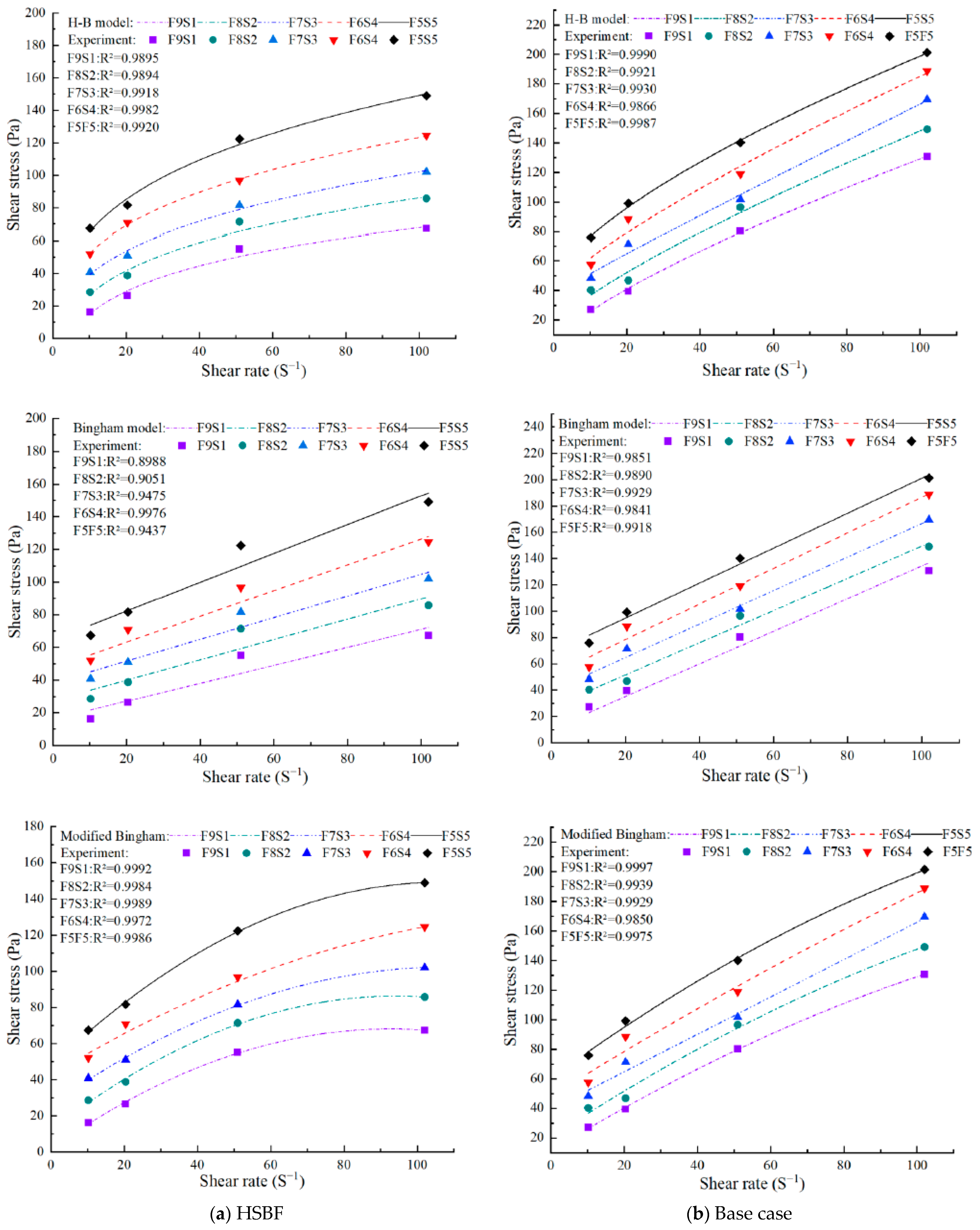
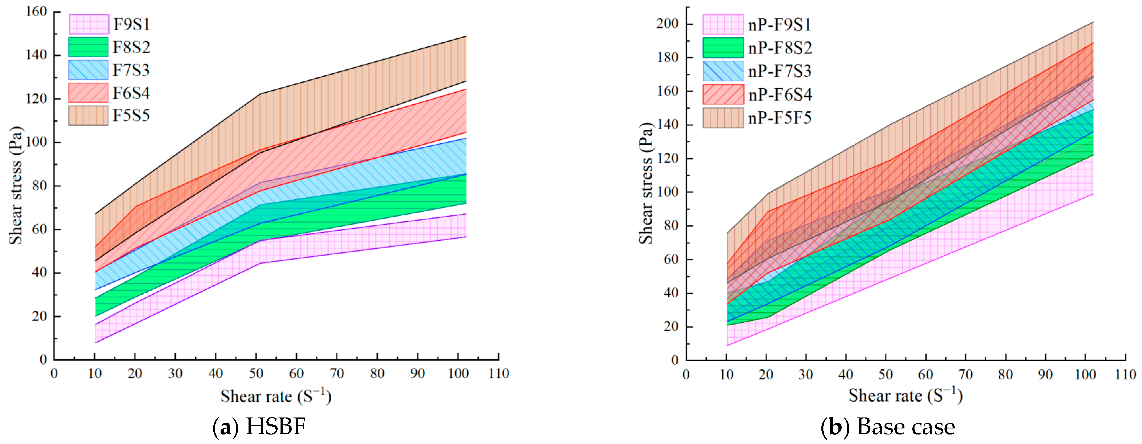
3.1. Rheological Properties

3.1.1. Yield Stress and Viscosity

The backfill material prepared with fly ash and slag essentially belongs to non-Newtonian fluids, similar to mortar and cementitious materials. Typically, their rheological properties can be characterized by representative models such as the Bingham model, the Modified Bingham (M-B) model, and the Herschel–Bulkley (H-B) model [30,31]. The experimental measurements were fitted to the mentioned models, and the fitting results are shown in Figure 3. The rheological curves of the fresh slurry agreed with the H-B and M-B models. The formula for the H-B model is given as follows [32]:
τ = τ 0 + K γ ˙ n , τ τ o
In the equation, τ represents shear stress; τ0 is the yield stress; K is the consistency index; and n is the flow behavior index. When n > 1, the material exhibits shear-thickening characteristics, known as an expansive plastic fluid; when n < 1, the material shows shear-thinning characteristics, referred to as pseudoplastic fluid; and when n = 1, the material follows the Bingham model [33]. The regression equation and rheological parameters for the fitted H-B model are shown in Table 4.
Table 4 shows that the flow behavior index (n) for the backfill slurry is less than 1, indicating that the backfill slurry essentially exhibits shear-thinning characteristics. However, the fitted yield stress is negative for the PDMS-modified backfill slurry, which contradicts the nature of yield stress. Therefore, the H-B model is not suitable for describing the rheological properties of the hydrophobic backfill slurry.
The equation and fitting results of the M-B model are shown in Equation (2) [34] and Figure 3, respectively. It can be observed that the shear stress is positively correlated with the applied shear rate. At the same shear rate, the shear stress gradually increased with the concentrated slag. Compared to the spherical and granular shape of fly ash, slag has a more irregular particle shape. The addition of slag increased the specific surface area and interactions between particles, leading to particle aggregation and adversely affecting the rheological properties of the slurry [35]. After the addition of PDMS, the rheological performance of the slurry still showed a positive correlation. However, the increase in shear stress became less significant when the shear rate exceeded 51 s−1. Compared to the reference group, PDMS inclusion led to a better flowability of the fresh backfill slurry at higher shear rates. This was plausibly due to the surface action of PDMS between slurry particles.
τ = τ 0 + η γ ˙ + c γ ˙ 2
In the equation, η is the rheological index, Pa·s; c is the correction factor. The regression equation and rheological parameters of the fitted M-B model are shown in Table 5. When using the M-B model, the fitting coefficients of the rheological curves for each group of samples were above 0.98. The fitting coefficients of the samples with added PDMS were above 0.99, indicating a high correlation. Therefore, the M-B model is more suitable for describing the rheological characteristics of hydrophobic backfill materials.
The yield stress is the minimum shear stress required for the slurry to flow. A comparison reveals that the yield stress of the backfill slurry increased with the addition of slag. For example, the yield stress of nP-F9S1 and nP-F5S5 increases from 11.25 Pa to 60.23 Pa. The increase in yield stress was attributed to the larger specific surface area and irregular particle shape of the slag, allowing it to absorb more free water. As described in the document in [36], the adsorption of water molecules leads to particle stacking, resulting in an increase in inter-particle interactions. Thus, yield stress increases.
The addition of PDMS significantly reduces the yield stress of the backfill slurry. For instance, the yield stress of nP-F5S5 decreased from 60.23 Pa to 47.81 Pa, and nP-F9S1 decreased from 11.25 Pa to 1.76 Pa when compared to F5S5 and F9S1, respectively. The reduction might be attributed to PDMS forming as a barrier between particles, reducing intermolecular interactions. The respected yield stress was thus decreased. As discussed in the literature [37], the strong chemical bonding inherent within siloxane (-Si-O-) networks, as well as their thermal stability, promotes inertness against chemical attack. Hence, PDMS works as a protective coating on fly ash and slag particles. Another reason is that during the alkali activation of fly ash and slag, C-S(A)-H gel is formed [38,39]. The forming gel binds the surrounding particles, causing particle aggregation and an increase in slurry viscosity [40]. The addition of PDMS suppressed the early formation of C-S(A)-H gel, resulting in lower viscosity and a significant reduction in yield stress [41].
To ensure the slurry transportation in pipeline, the yield stress of the fresh backfill slurry should be controlled within 200 Pa [42]. The yield stress of the hydrophobic backfill slurry was below 50 Pa, indicating good pumpability.

3.1.2. Thixotropy Analysis
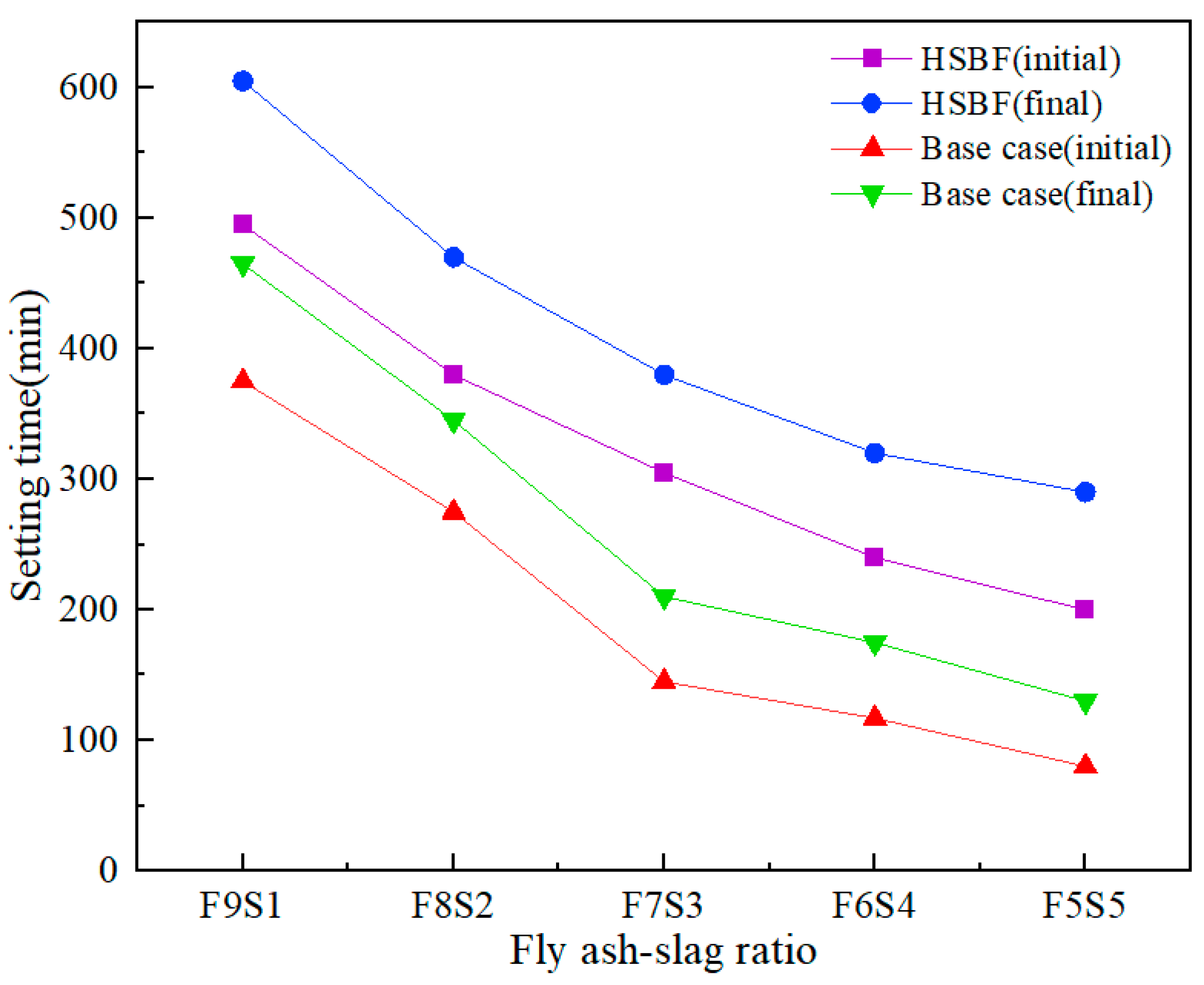
Thixotropy refers to the property of a material where its internal structure undergoes destruction after shear but rebuilds when shear stops or slows down [43]. The thixotropic hysteresis loop typically consists of ascending and descending curves. The ascending curve represents the process of reduced internal viscosity during shear, while the descending curve represents the rebuilding of the internal structure. The thixotropic properties of materials are often evaluated by calculating the area between the ascending and descending curves [44]. The thixotropic study of hydrophobic backfilling materials is shown in Figure 4.
As observed, regardless of the addition of hydrophobic agents, the thixotropic loop gradually increases with the addition of slag, indicating that slag has a significant effect on the thixotropic properties of the material. This is because the activity of slag is greater than that of fly ash [45], the hydration products are physically wrapped, and there is surface adsorption, chemical precipitation, etc. [46,47], so heavy metal ions are bound in the solidified body of slag, which promotes the interaction between particles. The internal structure of the high-slag-content slurry was more likely to undergo destruction and rebuilding during the shearing process, leading to an increase in thixotropic behavior.
With the addition of PDMS, the thixotropic behavior significantly decreased. Due to the bridging effect of SCA, PDMS can be connected to inorganic molecules such as slag and fly ash [7]. PDMS then reduces molecular aggregation, lowering interactions between molecules. Therefore, the destruction and rebuilding of particles are reduced during shearing, resulting in decreased thixotropic behavior.

3.2. Setting Time

The setting times were measured, and the results are shown in Figure 5.
It can be observed that the slag content and the addition of hydrophobic agents significantly influenced the setting times. The initial setting times of nP-F9S1 and nP-F5S5 are 375 min and 80 min, with final setting times of 465 min and 130 min, respectively. The addition of slag led to a significant reduction in the setting time. This is attributed to the higher reactivity of slag compared to fly ash [48]. The early hydration reactions involving slag result in the formation of C-S(A)-H colloids and calcium aluminate phases (Aft), creating a dense skeleton structure. This not only effectively enhances the strength of the specimens but also shortens the setting time. The setting time for samples with PDMS decreased. The initial setting times for F9S1 and F5S5 are 495 min and 200 min, with final setting times of 605 min and 290 min, respectively.
For the reference group, without adding hydrophobic agents, the setting time undergoes a turning point around nP-F7S3, and the rate of reduction slows down after nP-F7S3. This is due to the lower reactivity of fly ash in nP-F9S1 and nP-F9S1. So, a longer reaction time is required. This phenomenon significantly weakens after the addition of PDMS, because PDMS hinders the hydration reaction, which inhibits the aggregation of molecules and the adsorption of molecules by gels [49]. Due to the action of PDMS, the interval between the initial and final setting times of the hydrophobic slurry increased by 2 h on average compared to the reference group.
Considering the impact of transportation distance, the setting time should not be too short. Generally, the transportation distance from the mixing station to the void filling area exceeds 2 km, with a transportation duration over 2 h [50]. The hydrophobic backfill materials can meet these requirements.

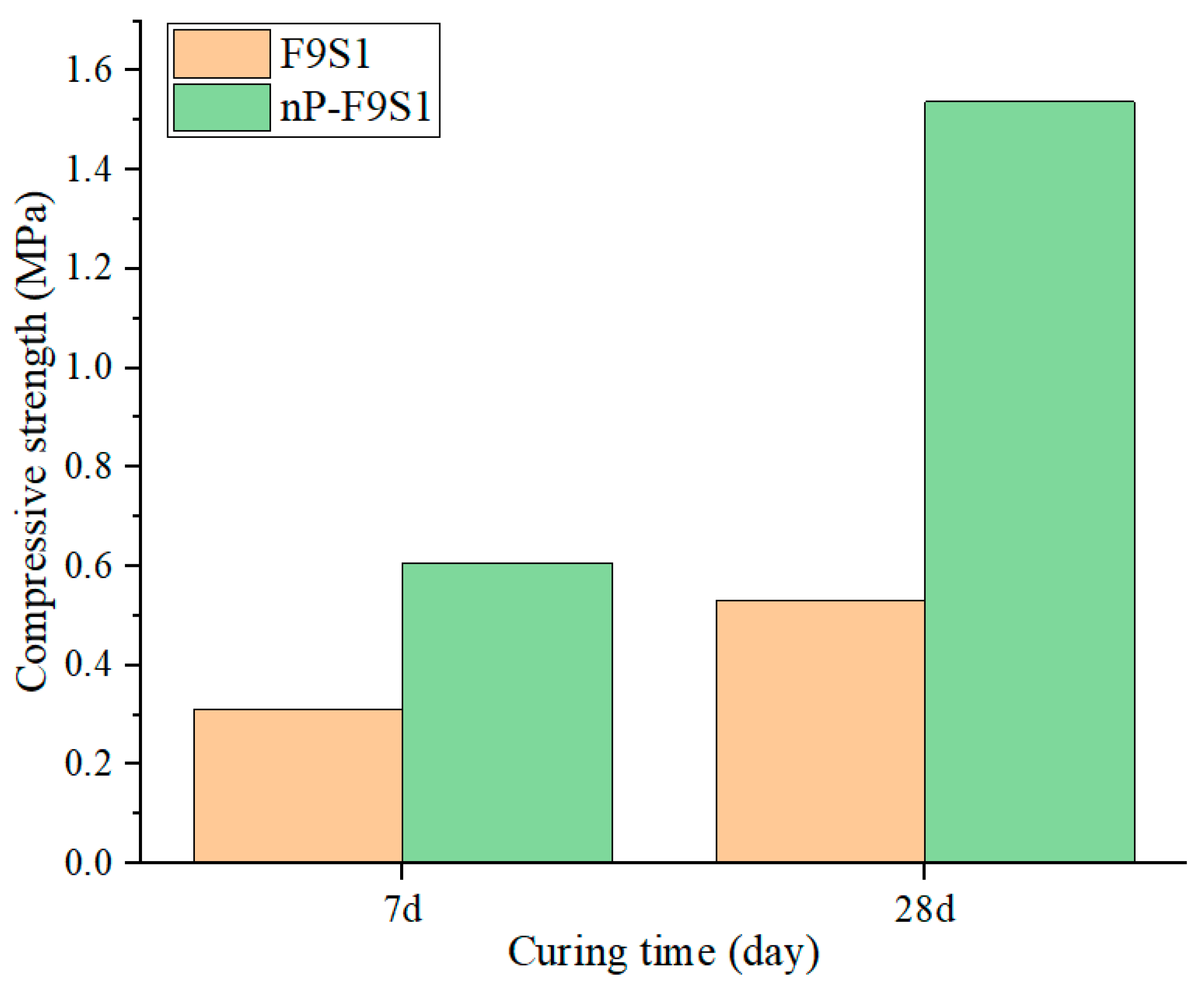
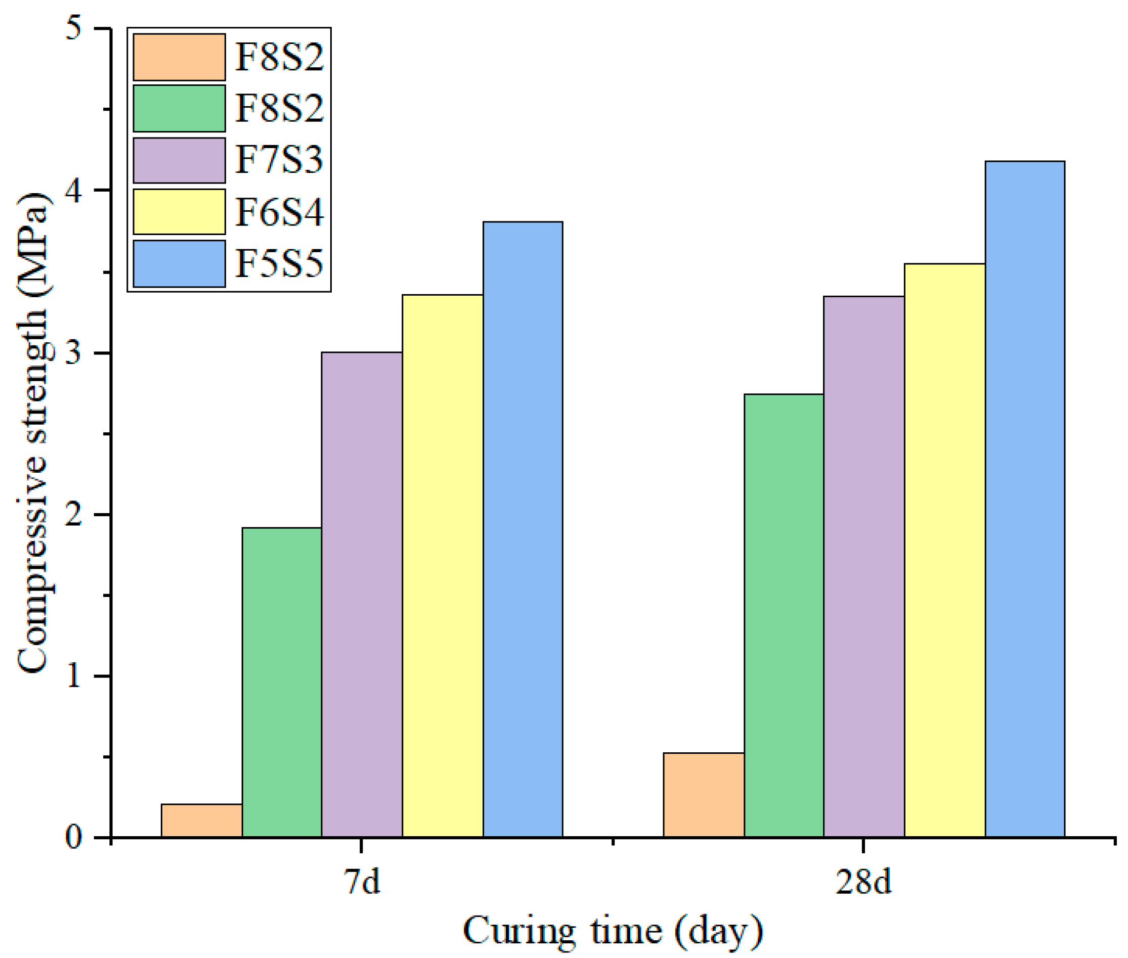
3.3. UCS Development of the Backfill Samples

The UCSs of HSBF materials were plotted against the reference sample, as shown in Figure 6.
As expected, the mechanical properties of the backfill material increased with curing time. The hydration reaction is a continuous process, and as the curing time extends, the gel material produced by the hydration reaction continues to increase, aggregating the particles together and enhancing the mechanical performance.
The introduction of PDMS weakens the strength of hydrophobic samples compared to the control group. As shown in Figure 6, the UCS of hydrophobic samples is reduced by approximately 50% compared to the control group after 7 d of curing. After 28 d of curing, the UCS is reduced by around 65%. In the control group without PDMS, hydration reactions continue, and the UCS of the samples steadily increases with prolonged curing time. PDMS in hydrophobic samples chemically couples to the molecular surfaces of slag and fly ash through the SCA, inhibiting subsequent hydration reactions. Therefore, the strength of hydrophobic samples is weakened compared to the control group, and the degree of reduction increases with extended curing time.
From Figure 7, it can be observed that the UCS of the samples increases with the increasing slag content. The UCSs of F9S1 were 0.21 MPa and 0.53 MPa after 7 d and 28 d of curing, respectively. The F9S1 sample carried a higher fly ash content, which was mainly composed of illite and quartz. Since illite crystals are generally less reactive, they thus make fly ash less effective for producing binding agents than slag [51], resulting in lower mechanical performance. The addition of slag improves the mechanical properties of the hydrophobic backfill material. The UCS at 28 d for F8S2 was 2.75 MPa, while that of F5S5 was 4.19 MPa. This improvement is attributed to the alkali-activated reaction of slag, forming a dense Si-O-Al three-dimensional network structure. Furthermore, a large amount of Ca2+ accompanies the formation of a substantial amount of hydrated calcium silicate, enhancing the mechanical performance of the binder material [30,52].
Backfill materials for goaf support must have a particular strength to support the overlying strata. Generally, it is required that the minimum UCS of backfill material samples after 28 d of curing should be between 0.7 and 2 MPa [53]. The UCS of the hydrophobic samples is above 2.7 MPa, satisfying the strength requirements.

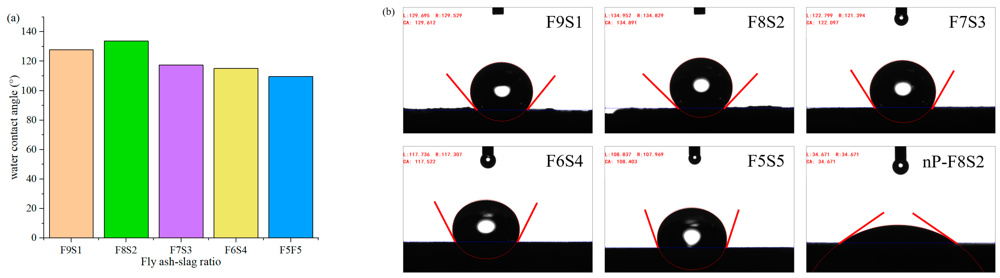
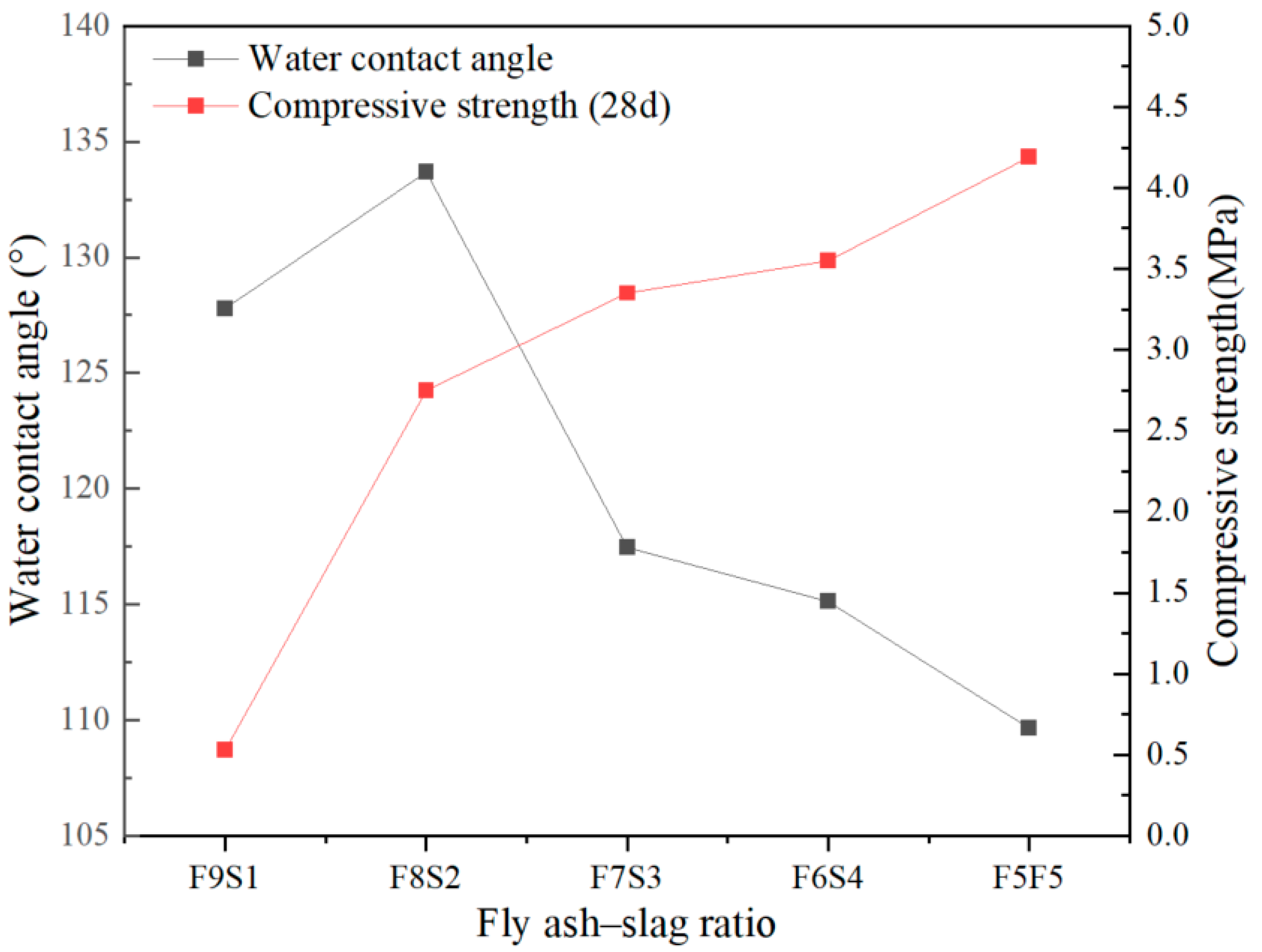
3.4. Water Contact Angle

To validate the hydrophobic performance of the HSBF material, water contact angle tests were conducted on samples cured for 28 d, and the results are shown in Figure 8. The material’s hydrophilic or hydrophobic properties are defined based on the range of the contact angle. If the contact angle formed by a water droplet on a solid surface is greater than 90°, indicating that the water droplet cannot adhere well to the solid surface (forming a bead), and there is a smaller contact area, it suggests that the solid surface is hydrophobic. If the formed contact angle is less than 90°, the water droplet will spread on the solid surface, indicating that the solid surface is hydrophilic [54]. According to the measurement results, F8S2 possessed the highest water contact angle at 134.9°. As the slag content increased, the contact angles of F7S3, F6S4, and F5S5 gradually decreased. This is because the C-S(A)-H gel formed in the early reaction of slag is not conducive to the adhesion of PDMS [55]. However, C-S(A)-H gel can effectively improve the strength of HSBF. Therefore, for HSBF with 20% to 50% slag content, hydrophobicity is inversely proportional to UCS.
Notably, the smallest water contact angle was 108.4° in the F5S5 sample. It was still greater than 90°, indicating hydrophobicity. To confirm that the hydrophobic property of the material is not determined by the inherent properties of slag and fly ash, the contact angle of nP-F8S2 was tested as a control case. The water contact angle of nP-F8S2 is 34.7°, indicating hydrophilicity. The control test of the reference group indicates that PDMS mainly confers the hydrophobic performance and is not related to the inherent properties of slag and fly ash.
It can be seen from Figure 9 that when the slag content increased from 20% to 50%, the change in the water contact angle of the hydrophobic backfill body was negatively correlated to that of UCS. In terms of hydrophobicity, the five groups of backfill materials with different fly ash–slag ratios have good hydrophobic responses. When considering the mechanical properties of HSBF, the 28 d UCS strength of HSBF with 10% slag content does not meet the requirements. HSBF with a fly ash content between 20% and 50% has good hydrophobic properties and mechanical properties, which can be flexibly selected in practical applications.

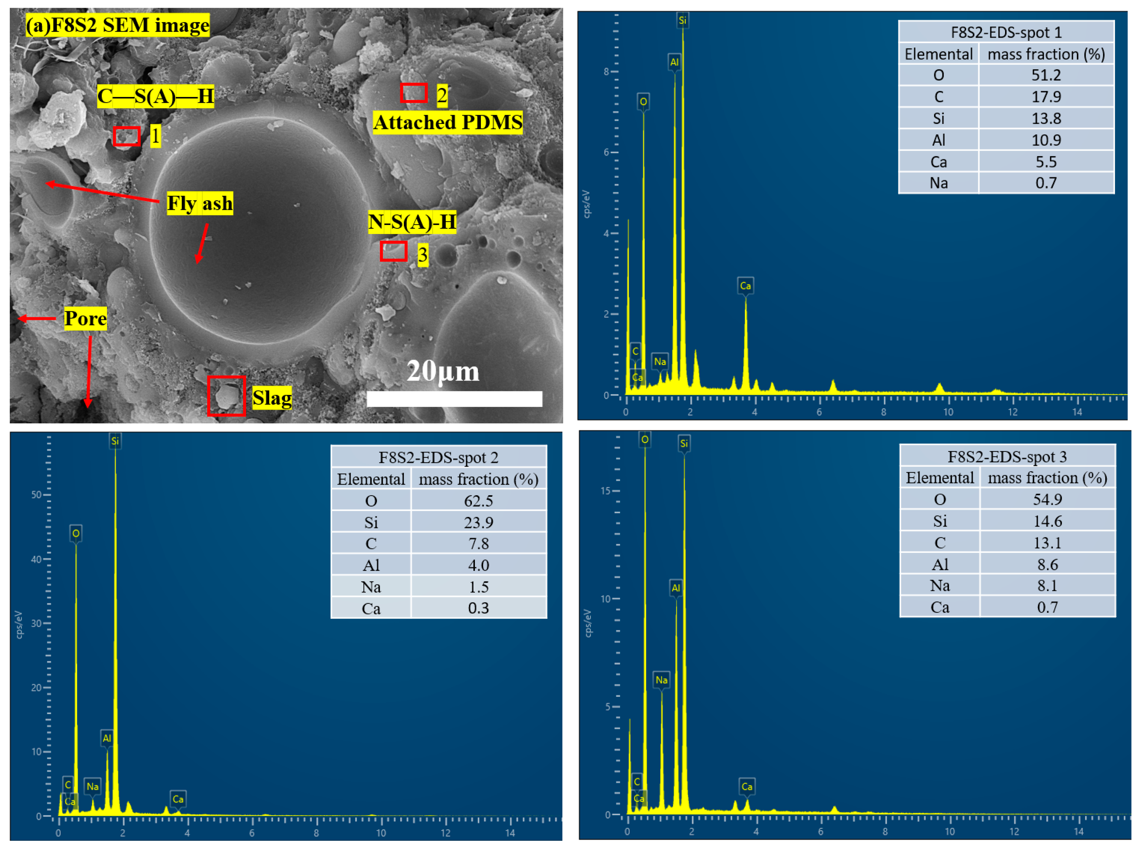
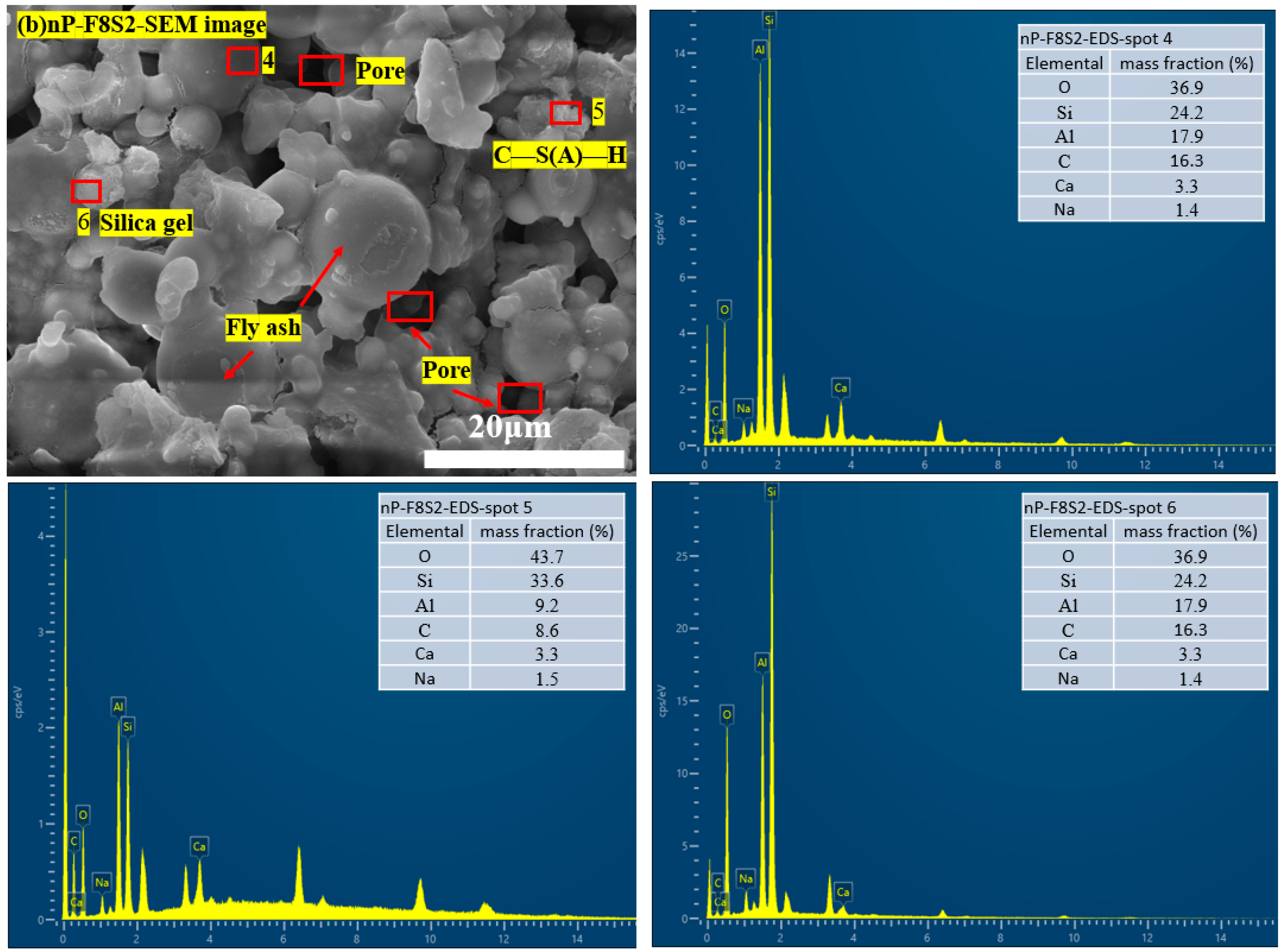
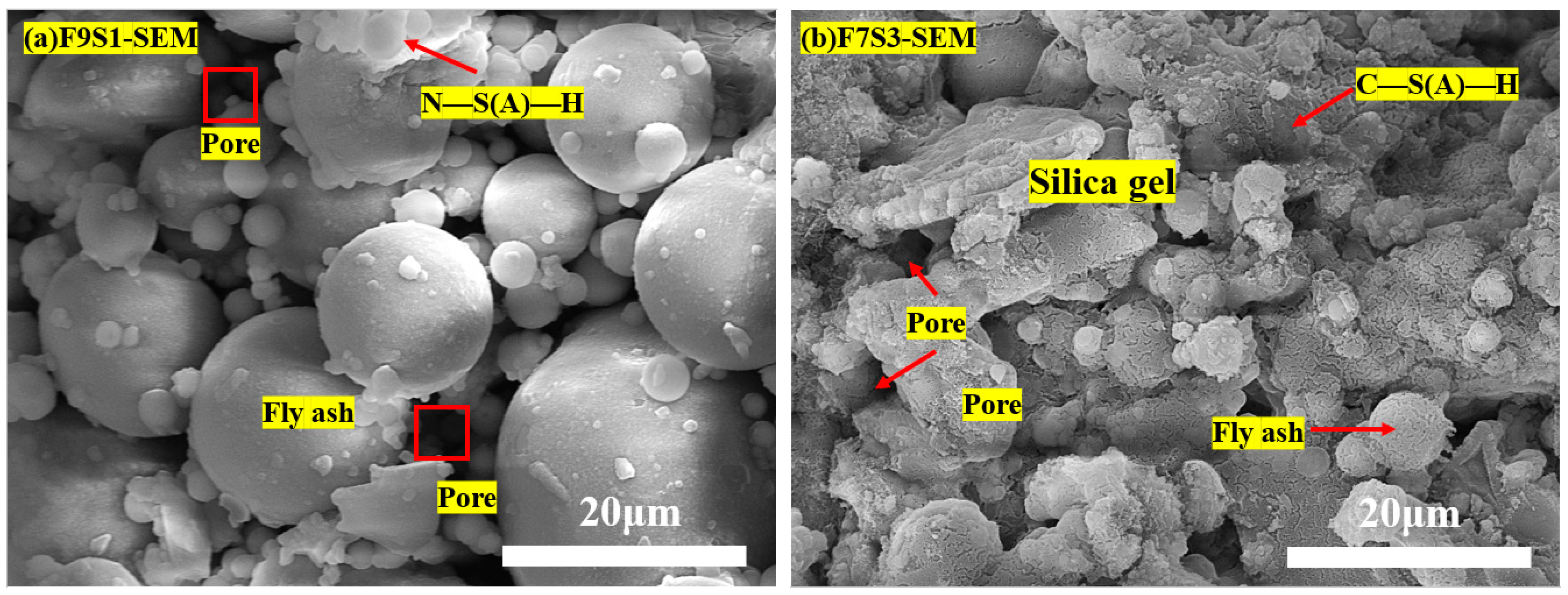
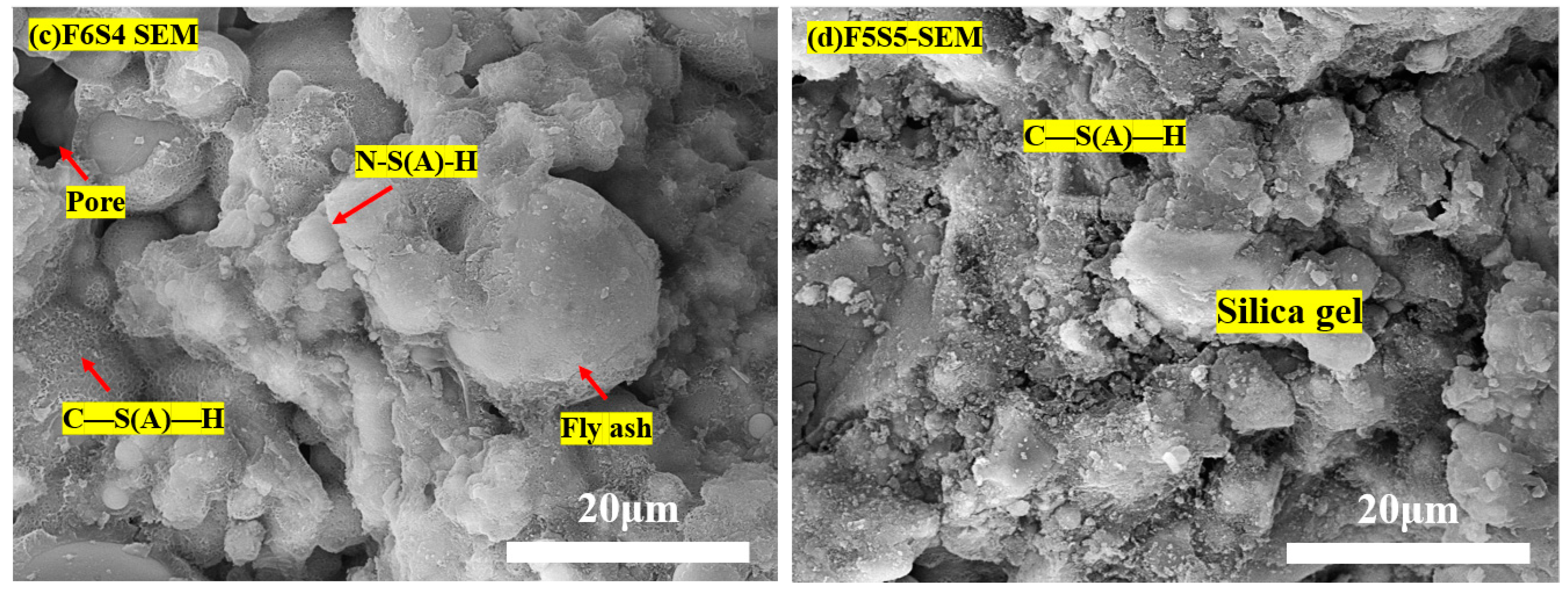
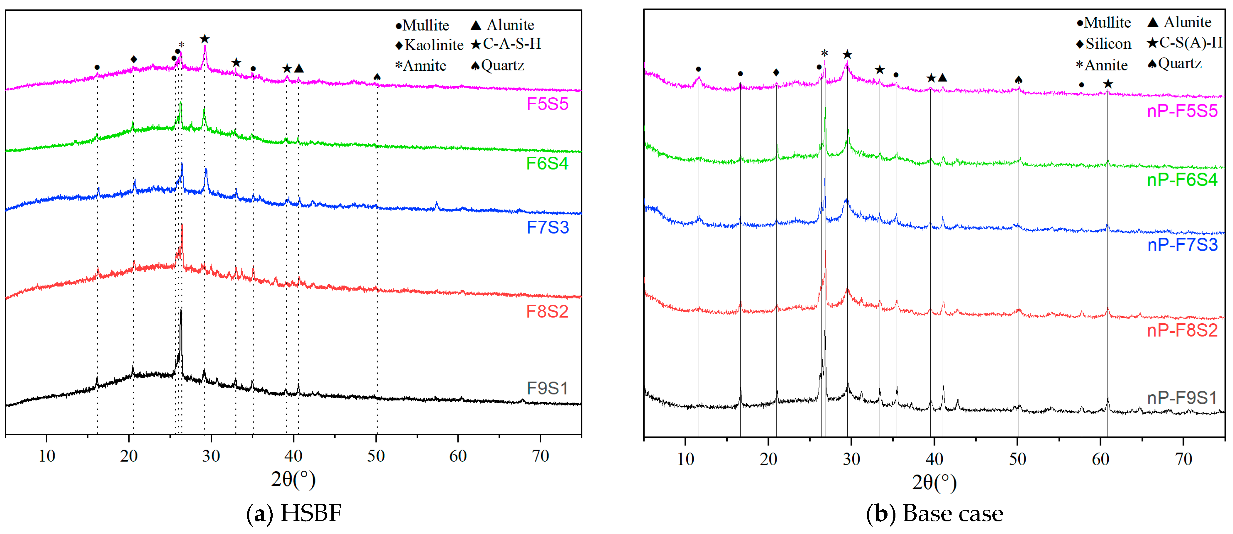
3.5. Microstructure and Hydration Products

Figure 10 shows the SEM images and EDS element analysis results of F8S2 and nP-F8S2 at 28 d.
The results indicated that the hydration products of slag and fly ash are mainly gel-like substances. At measurement point 1, a large amount of Si, Al, O, and Ca can be observed. Combined with the morphological analysis, it is identified that the C-S(A)-H gel rapidly formed in the early hydration reaction of slag [56]. The reaction of CaO in the slag produces Ca(OH)2, which combines with sufficient Al2O3 to form C-S(A)-H, as shown in Equations (3) and (4). Similarly, due to a large amount of Si, Al, and Ca, the gel substance at measurement point 5 is also identified as C-S(A)-H gel. Since F8S2 has a lower slag content, a large amount of fly ash failed to participate in the development of C-S(A)-H gel; thus, more unreacted fly ash can be seen in Figure 10a. Comparing the elemental content of Si, Al, Ca, and Na, it can be determined that measurement point 6 is silica gel [57]. Measurement points 2 and 4 are both fly ash surfaces. Both points have relatively low Ca and Na elemental contents, which plausibly resulted from the attachment of C-S(A)-H and N-S(A)-H. The fly ash at measurement point 4 is smooth, while the Si content at measurement point 2 is much higher than the Al content. PDMS (molecular formula: (CH3)3Si-O-[Si(CH3)2-O]n-Si(CH3)3) is a polymer composed of Si, O, and methyl (CH3) groups, containing a large amount of C, Si, and O elements. This matches the EDS element characteristics of measurement point 2. Therefore, measurement point 2 is identified as PDMS attached to the surface of fly ash. The main elements at measurement point 3 are O, Si, Al, and Na. The substance is in a gel state, and the Ca content is relatively low, identifying it as N-S(A)-H gel formed by the hydration of fly ash [58]. When fly ash reacted with sodium hydroxide solution, the alkaline environment led to the reaction of silicon oxide in the slag with sodium hydroxide, forming sodium silicate gel, as shown in Equation (5).
C a O + H 2 O C a ( O H ) 2
A l 2 O 3 + S i O 2 + C a ( O H ) 2 + H 2 O y C a O A l 2 O 3 S i O 2 n H 2 O
2 S i O 2 A l 2 O 3 + 3 O H + 3 H 2 O 2 A l ( O H ) 4 + [ S i O 2 ( O H ) 2 ] 2
By comparing the EDS information of F8S2 and nP-F8S2, it can be observed that the addition of PDMS does not significantly alter the products of the hydration reaction, and the main generated substances are still C-S(A)-H and N-S(A)-H gels.
To investigate the influence of different fly ash–slag ratios on the HSBF, the morphological characteristics of HSBF under four other slag ratios were compared. The results are shown in Figure 11.
When the fly ash–slag ratio is F9S1, a large number of free fly ash particles can be observed, leaving many voids between them, with only a tiny amount aggregating into clusters under the action of the gel. The loose particle structure gave F9S1 higher fluidity but led to a decrease in strength. As the slag content increased, there was almost no smooth fly ash surface in F7S3 compared to F8S2, but the fly ash was still relatively dispersed. With the continued increase in slag content, more blocky colloids can be observed. When the slag–fly ash ratio was 5:5, the C-S(A)-H gel generated by the slag wraps the fly ash, and almost no noticeable fly ash particles are observed.
To explore the mechanism of PDMS, SEM tests with resolutions of 5 μm and 1 μm were conducted on F8S2 and nP-F8S2, and the results are shown in Figure 12.
It can be seen from the results that a PDMS connection can be seen between the fly ash particles in the F8S2 (Figure 11a). PDMS is connected to inorganic substances such as fly ash and slag through the bridging effect of the SCA coupling agent.
The silane functional groups in the silane coupling agent reacted with the active sites (such as OH groups) on the PDMS surface to form a silicon–oxygen–silicon bond [59]. The formation of this covalent bond made the silane coupling agent firmly adhere to the PDMS surface. At the same time, the organic groups of the silane coupling agent can also react with the active sites on the surface of the slag and fly ash to form Si-O-inorganic surface bonds [44]. In this way, the originally inert PDMS is attached to the surface of inorganic molecules such as fly ash and slag through the bridging effect of the coupling agent to form a uniform and dense capillary structure (Figure 11b), which makes the backfill body hydrophobic. The addition of PDMS inhibited the activation reaction and reduced gel formation and fly ash molecule aggregation. The increase in slag content then generated a large number of dense and compact gel structures, which improve the strength characteristics. The test results match the rheological and strength properties of the slurry.

3.6. Hydration and Carbonation Products in the HSBF Sample

The results of XRD analysis of the HSBF samples after 28 d of curing are shown in Figure 13.
The graph shows that the XRD spectra of samples with added PDMS are similar in peak shape to those without PDMS, mainly containing diffraction peaks of mullite, SiO2, annite, and C-S(A)-H, which is consistent with previous studies [29,30]. Several shorter peaks can be observed in the XRD spectrum without PDMS, indicating that adding PDMS may have some adverse effects on XRD testing [49]. The observed annite peak gradually decreases with the addition of slag, and the corresponding C-S(A)-H peak gradually increases. Annite is generated from Al2O3 and SiO2 in fly ash in an alkaline environment. With the addition of slag, the CaO in the slag reacts to form C-S(A)-H gel, which adheres to the surface of fly ash, inhibiting the subsequent hydration of fly ash [47].
Overall, the XRD test results of the material after adding PDMS show no significant difference, indicating that no new substances are generated after adding PDMS, and PDMS does not participate in the hydration reaction.

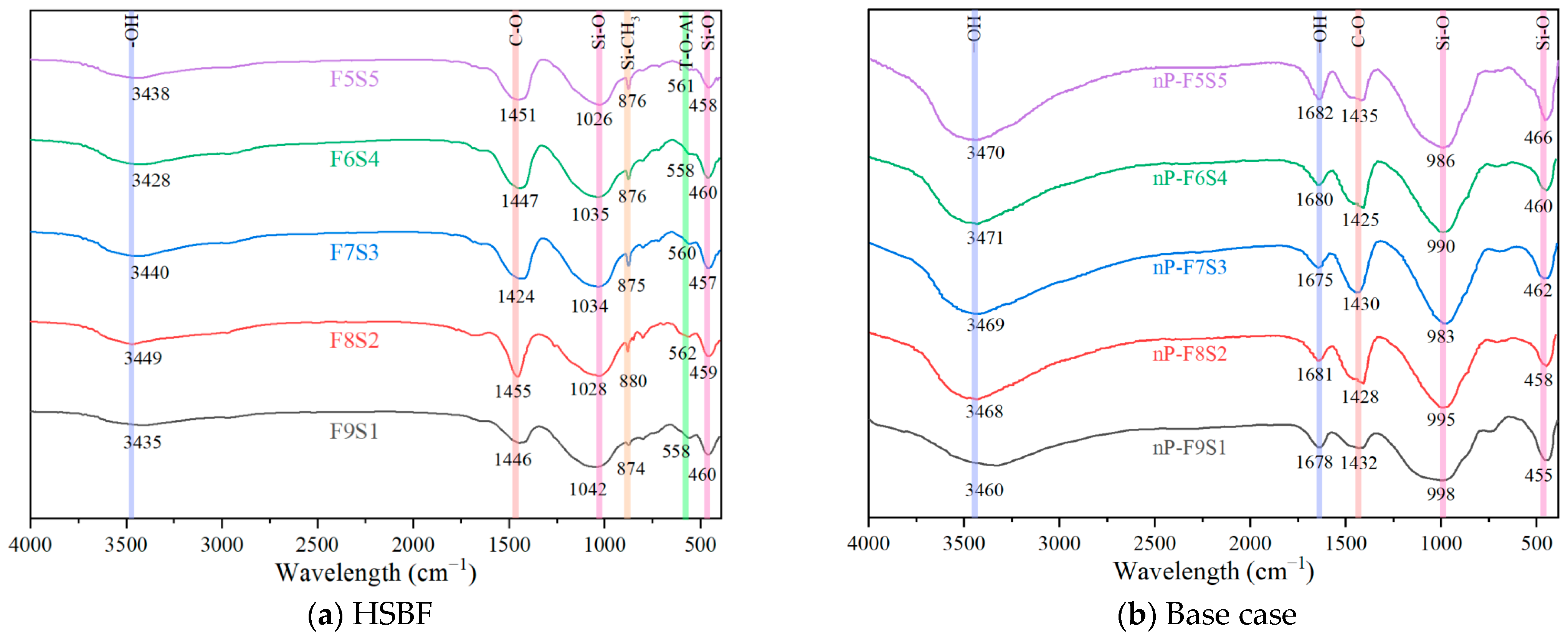
3.7. Infrared Spectroscopy Analysis

The results of the FTIR analysis are shown in Figure 14. The characteristic peaks at 1035 cm−1 and 990 cm−1 observed in the spectrum belong to the stretching vibration absorption peaks of Si-O. The peak at a low wavenumber of 460 cm−1 corresponds to the deformation vibration of Si-O. The intensity and position of the principal peak depend on the length and angle of the chemical bond [60]. The characteristic peak at 990 cm−1 was more considerable, indicating that more Si-O bonds were generated in the reference group [61] and the hydration reaction was sufficient, which confirmed that the addition of PDMS inhibited the hydration reaction to a certain extent. OH stretching vibration generates peaks at 3470 cm−1 and 3440 cm−1 [62]. Compared with the hydrophobic sample with PDMS, the OH stretching vibration peak of the reference group was more prominent and produced an additional OH stretching vibration peak at 1680 cm−1. Since the sample was dried before the test, this result indicated that the reference group contained more bound water. This is because the hydration reaction of the reference group is sufficient, and more hydration products are generated. The test results are consistent with the microstructure and mechanical properties tests.
The signal peak from 1400 cm−1 to 1450 cm−1 was produced by C-O bond vibration, which may be produced by sodium carbonate and calcium carbonate [63,64]. After adding PDMS, compared with the reference group, new characteristic absorption peaks appeared at 875 cm−1 and 562 cm−1: the narrow peak at 875 cm−1 was generated by the stretching vibration of the Si-CH3 bond of PDMS [65]. Because less PDMS was added, the peak value formed was smaller. Si-O-T (T represents the active group on the surface of inorganic molecules) formed by the interaction between the coupling agent and inorganic substances such as fly ash and slag at 562 cm−1 [66,67]. The formation of Si-O-T indicates that PDMS was attached to the surface of inorganic molecules such as fly ash and slag by a coupling agent. The more Si-O-T bonds are formed, the better the adhesion effect of PDMS, resulting in better hydrophobic performance. The test results are consistent with the water contact angle test results.

3.8. Strengths and Applications

In the design of the novel HSBF, the use of cement is ultimately eliminated. So, the backfill cost is significantly reduced, the comprehensive utilization rate of solid waste is improved, and the construction of green mines is actively promoted. The hydrophobic backfill material shows superior hydrophobic properties, which not only effectively reduce groundwater seepage but also ensure the stability of groundwater around the mining area. It also helps the filling body resist the corrosion-weakening effect of mine water. In addition, the advantages of high early strength and short setting time of the hydrophobic filling body also help to improve the filling efficiency.

4. Conclusions

Utilizing fly ash and slag as the primary raw materials, a novel hydrophobic solid backfill (HSBF) material has been developed by employing PDMS and SCA as hydrophobic modification agents. Experimental studies were conducted to evaluate its feasibility from rheological and mechanical perspectives. Additionally, morphological analyses (XRD, SEM, FTIR) were carried out to discover the underlying mechanisms of PDMS in HSBF. The following conclusions can be drawn:
(1)
The HSBF paste conforms to the Modified Bingham model and exhibits shear-thinning behavior. The thixotropy of the HSBF paste was consistent with the yield stress.
(2)
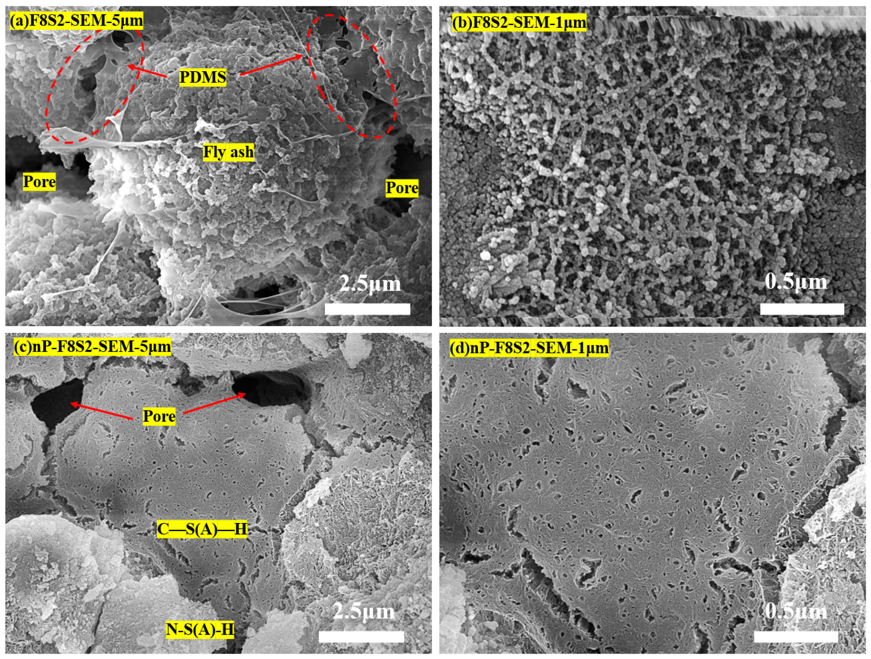
After PDMS hydrophobic modification, the water contact angle of the backfill material increased up to 134.9°, exhibiting excellent hydrophobic properties. SEM, XRD, and FTIR tests showed that the PDMS adhered to the surface of inorganic molecules such as fly ash and slag through the bridging action of the coupling agent to form a dense capillary structure, which gave the backfill a hydrophobic effect.
(3)
The overall strength of HSBF increased up to 98% by increasing the slag content from 20 to 50% through the fly ash–slag ratio optimization. The strength enhancement was obtained by the greater development in C-S(A)-H gel, which was achieved in the case of high slag content.
(4)
This research demonstrates that HSBF with various slag ratios (F8S2, F7S3, F6S4, F5F5) exhibits excellent mechanical performance and hydrophobic characteristics. The novel developed HSBF materials are feasible to implement in underground construction with active water interaction.

Author Contributions

Conceptualization, I.N. and L.M.; methodology, I.N. and Z.Z..; software, M.H.S.; validation, K.Y., C.P. and S.S.A.; formal analysis, I.N.; investigation, J.Z.; resources, Y.X.; data curation, Q.G.; writing—original draft preparation, Z.Z.; writing—review and editing, Z.Z.; visualization, D.W.; supervision, L.M.; project administration, I.N.; funding acquisition, I.N. All authors have read and agreed to the published version of the manuscript.

Funding

This research was funded by the National Natural Science Foundation of China grant number 52250410338 (Ichhuy Ngo), the Research and Engineering Demonstration of Low Cost Large Scale Purification and Cascade Utilization Technology for Mining Brackish Water in the Zhundong Region grant number 2023B03009 (Liqiang Ma), Foundation Research Funds of the Central Universities grant number 2021ZDY0211 (Liqiang Ma), the Key Laboratory of Xinjiang Coal Resources Green Mining of Ministry of Education (Xinjiang Institute of Engineering, grant number KLXGY-KA2403 (Ichhuy Ngo),the National Natural Science Foundation of China grant number 51874280 (Liqiang Ma), the Scientific Research Foundation for High-level Talents of Anhui University of Science and Technology grant number 2023yjrc89 (Yujun Xu), the Postgraduate Research & Practice Innovation Program of Jiangsu Province grant number KYCX23_2811 (Qiangqiang Gao), the Graduate Innovation Program of China University of Mining and Technology 2023WLKXJ046 (Qiangqiang Gao), and the Researchers Supporting Project number RSP2024R496, King Saud University, Riyadh, Saudi Arabia (Saad S. Alarifi).

Data Availability Statement

The data presented in this study are available on request from the corresponding author due to privacy and ethical restrictions to ensure lawful use of the data.

Conflicts of Interest

The authors declare no conflict of interest.

References

  1. Zhou, L.B.; Sun, X.H.; Liu, Z.; Wang, D.M.; Zhu, L. Study on preparation, working performance and microstructure of coal mine filling material with large amount of fly ash. J. China Coal Soc. 2023, 48, 4536–4548. [Google Scholar] [CrossRef]
  2. Yang, Y.X.; Wang, K.Y.; Ren, L. Evaluation and coupling coordination analysis of high quality development of China’s coal industry: Empirical research based on data from 2000 to 2019. J. Min. Sci. Technol. 2021, 6, 764–776. [Google Scholar] [CrossRef]
  3. Jiang, L. Comprehensiveutilization situation of fly ash in coal—Fired power plants and its development suggestions. Clean Coal Technol. 2020, 26, 31–39. [Google Scholar] [CrossRef]
  4. Zhang, J.X.; Zhang, Q.; Zhou, N.; Li, M.; Huang, P.; Li, B. Research progress and prospect of coal based solid waste backfilling mining technology. J. China Coal Soc. 2022, 47, 4167–4181. [Google Scholar] [CrossRef]
  5. Yang, K.; Zhao, X.Y.; He, X.; Wei, Z. Basic theory and key technology of multi-source coal-based solid waste for green backfilling. J. China Coal Soc. 2022, 47, 4201–4216. [Google Scholar] [CrossRef]
  6. Yin, S.; Yan, Z.; Chen, X.; Yan, R.; Chen, D.; Chen, J.; Li, G. Active roof-contact: The future development of cemented paste backfill. Constr. Build. Mater. 2023, 370, 130657. [Google Scholar] [CrossRef]
  7. Feng, Y.; Qi, W.; Zhao, Q.; Huang, Y.; Ren, Q.; Qi, W.; Kong, F. Synthesis and characterization of cemented paste backfill: Reuse of multiple solid wastes. J. Clean. Prod. 2023, 383, 135376. [Google Scholar] [CrossRef]
  8. Wang, Y.Y. Study on Strengthening Mechanism and Application of CO2 Mineralized Solid Waste Backfill Materials; China University of Mining and Technology: Xuzhou, China, 2023. [Google Scholar] [CrossRef]
  9. Ding, J.; Feng, Z.; Sun, D.; You, K.; Yan, M.; Xun, Y. Analysis of Influencing Factors of Silt Solidified Soil in Flowing State. World J. Eng. Technol. 2019, 7, 455–464. [Google Scholar] [CrossRef]
  10. Shao, L.; Li, P.Q.; Wang, B.J. Analysis of the strength characteristics of soft soil reinforced by composite excited blast furnace slag. China Water Transp. 2021, 21, 154–156. [Google Scholar]
  11. Luo, H.G.; Liu, H.S.; Li, P.; Zhang, P.H.; Wu, R. Optimisation Test of Ratio of Sand-based Paste Filling Materials in Shendong Mine. Coal Tech-Nology 2023, 42, 45–49. [Google Scholar] [CrossRef]
  12. Peng, Y.; Zhao, G.; Qi, Y.; Zeng, Q. In-situ assessment of the water-penetration resistance of polymer modified cement mortars by μ-XCT, SEM and EDS. Cem. Concr. Compos. 2020, 114, 103821. [Google Scholar] [CrossRef]
  13. Song, J.; Li, Y.; Xu, W.; Liu, H.; Lu, Y. Inexpensive and non-fluorinated superhydrophobic concrete coating for anti-icing and anti-corrosion. J. Colloid Interface Sci. 2019, 541, 86–92. [Google Scholar] [CrossRef] [PubMed]
  14. Hou, J.; Guo, Z.; Liu, W.; Zhang, Y. Mechanical properties and meso-structure response of cemented gangue-fly ash backfill with cracks under seepage- stress coupling. Constr. Build. Mater. 2020, 250, 118863. [Google Scholar] [CrossRef]
  15. Ngo, I.; Ma, L.; Zhai, J.; Wang, Y.; Wei, T. Durability of CO2-fly ash-based backfill materials in cation water deterioration. Int. J. Min. Reclam. Environ. 2023, 1–24. [Google Scholar] [CrossRef]
  16. Guo, Y.X.; Ran, H.; Feng, G.; Wang, P. Strength and creep characteristics of cemented gangue backfill in acid environment. J. Min. Saf. Eng. 2021, 38, 361–369. [Google Scholar] [CrossRef]
  17. Sidhu, J.; Kumar, P. Comprehensive review on hydrophobic modification of concrete: Progress and perspectives. Adv. Civ. Arch. Eng. 2023, 14, 155–180. [Google Scholar] [CrossRef]
  18. Konstantin, G.S.; Batrakov, V.G. Effect of a polyethylhydrosiloxane admixture on the durability of concrete with supplementary cementitious materi-als. J. Mater. Civ. Eng. 2007, 19, 809–819. [Google Scholar]
  19. Wong, H.S.; Barakat, R.; Alhilali, A.; Saleh, M.; Cheeseman, C.R. Hydrophobic concrete using waste paper sludge ash. Cem. Concr. Res. 2015, 70, 9–20. [Google Scholar] [CrossRef]
  20. Wang, X.Y.; Zhang, C.; Sun, S.; Kalulu, M.; Chen, L.; Zhou, X.; Jiang, Y. Durable superhydrophobic coating based on inorgan-ic/organic double-network polysiloxane and functionalized nanoparticles. Colloids Surf. A Physicochem. Eng. Asp. 2019, 578, 123550. [Google Scholar] [CrossRef]
  21. Flores-Vivian, I.; Hejazi, V.; Kozhukhova, M.I.; Nosonovsky, M.; Sobolev, K. Self-assembling particle-siloxane coatings for superhydrophobic concrete. ACS Appl. Mater. Interfaces 2013, 5, 13284–13294. [Google Scholar] [CrossRef]
  22. Wang, F.; Lei, S.; Ou, J.; Xue, M.; Li, C.; Li, W. Superhydrophobic calcium aluminate cement with super mechanical stability. Ind. Eng. Chem. Res. 2019, 58, 10373–10382. [Google Scholar] [CrossRef]
  23. Shao, Y. Immobilization Mechanisms of Solidified Municipal Solid Waste Incineration Fly Ash Using Blast Furnace Slag Based Cementitious Material; Wu Han University: Wuhan, China, 2014. [Google Scholar]
  24. Zhou, W. Study of the Properties and Preparation of PDMS Coating Material; Wuhan University of Technology: Wuhan, China, 2007. [Google Scholar]
  25. GB/T 17671-2021; Test Method of Cement Mortar Strength (ISO Method). China Cement Standardization Technical Committee (SAC/TC 184): Beijing, China, 2021.
  26. ASTM C150; Standard Specification for Portland Cement. American Society for Testing and Materials (ASTM) International: West Conshohocken, PA, USA, 2017.
  27. Ma, L.; Zhai, J.; NGO Ichhuy. Experimental study on preparation of negative carbon filling material forwater protection mining by CO2mineralization of coal-based solid waste. J. China Coal Soc. 2022, 47, 4228–4236. [Google Scholar] [CrossRef]
  28. Ngo, I.; Ma, L.; Zhai, J.; Wang, Y. Enhancing fly ash utilization in backfill materials treated with CO2 carbonation under ambient conditions. Int. J. Min. Sci. Technol. 2023, 33, 323–337. [Google Scholar] [CrossRef]
  29. Kwok, D.Y.; Neumann, A.W. Contact angle measurement and contact angle interpretation. Adv. Colloid Interface Sci. 1999, 81, 167–249. [Google Scholar] [CrossRef]
  30. Ihle, C.F.; Tamburrino, A. Analytical solutions for the flow depth of steady laminar, Bingham plastic tailings down wide channels. Miner. Eng. 2018, 128, 284–287. [Google Scholar] [CrossRef]
  31. Ettehadi, A.; Altun, G. Functional and practical analytical pressure surges model through herschel bulkley fluids. J. Pet. Sci. Eng. 2018, 171, 748–759. [Google Scholar] [CrossRef]
  32. Saramito, P. A new elastoviscoplastic model based on the Herschel–Bulkley viscoplastic model. J. Non-Newton. Fluid Mech. 2009, 158, 154–161. [Google Scholar] [CrossRef]
  33. de Larrard, F.; Ferraris, C.F.; Sedran, T. Fresh concrete: A Herschel-Bulkley material. Mater. Struct. 1998, 31, 494–498. [Google Scholar] [CrossRef]
  34. Zhaidarbek, B.; Tleubek, A.; Berdibek, G.; Wang, Y. Analytical predictions of concrete puming: Extending the Khatib–Khayat model to Herschel–Bulkley and modified Bingham fluids. Cem. Concr. Res. 2023, 163, 107035. [Google Scholar] [CrossRef]
  35. Palacios, M.; Banfill, P.; Puertas, F. Rheology and setting of alkali-activated slag pastes and mortars: Effect of organ admixture. ACI Mater. J. 2008, 105, 140–148. [Google Scholar]
  36. Kashani, A.; Provis, J.L.; Qiao, G.G.; van Deventer, J.S. The interrelationship between surface chemistry and rheology in alkali activated slag paste. Constr. Build. Mater. 2014, 65, 583–591. [Google Scholar] [CrossRef]
  37. Eduok, U.; Faye, O.; Szpunar, J. Recent developments and applications of protective silicone coatings: A review of PDMS func-tional materials. Prog. Org. Coat. 2017, 111, 124–163. [Google Scholar] [CrossRef]
  38. Puertas, F.; Palacios, M.; Manzano, H.; Dolado, J.S.; Rico, A.; Rodríguez, J. A model for the CASH gel formed in alkali-activated slag cements. J. Eur. Ceram. Soc. 2011, 31, 2043–2056. [Google Scholar] [CrossRef]
  39. Fernández-Jiménez, A.; Puertas, F.; Sobrados, I.; Sanz, J. Structure of calcium silicate hydrates formed in alkaline-activated slag: Influence of the type of alkaline activator. J. Am. Ceram. Soc. 2003, 86, 1389–1394. [Google Scholar] [CrossRef]
  40. Gonzalez-Taboada, I.; Gonzalez-Fonteboa, B.; Martinez-Abella, F.; Seara-Paz, S. Thixotropy and interlayer bond strength of self-compacting recycled concrete. Constr. Build. Mater. 2018, 161, 479–488. [Google Scholar] [CrossRef]
  41. Ruan, S.; Chen, S.; Lu, J.; Zeng, Q.; Liu, Y.; Yan, D. Waterproof geopolymer composites modified by hydrophobic particles and polydimethylsiloxane. Compos. Part B Eng. 2022, 237, 109865. [Google Scholar] [CrossRef]
  42. Sellgren, A.; Addie, G.; Whitlock, L. Technical-economical feasibility of using centrifugal pumps in high-density thickened tailings slurry systems. In Proceedings of the Paste2005: Proceedings of the International Seminar on Paste and Thickened Tailings, Santiago, Chile, 20–22 April 2005; Australian Centre for Geomechanics: Crawley, Australia, 2005; pp. 195–204. [Google Scholar] [CrossRef]
  43. Khayat, K.H.; Saric-Coric, M.; Liotta, F. Influence of thixotropy on stability characteristics of cement grout and concrete. Mater. J. 2002, 99, 234–241. [Google Scholar]
  44. Khayat, K.H.; Omran, A.; Magdi, W.A. Evaluation of thixotropy of self-consolidating concrete and influence on concrete per-formance. In Proceedings of the 3rd Iberian Congress on Self Compacting Concrete, Madrid, Spain, 8–10 December 2012; pp. 3–16. [Google Scholar]
  45. Wardhono, A.; Gunasekara, C.; Law, D.W.; Setunge, S. Comparison of long term performance between alkali activated slag and fly ash geopolymer concretes. Constr. Build. Mater. 2017, 143, 272–279. [Google Scholar] [CrossRef]
  46. Long, L. Mechanism Study on Solidification and Stabilization of Municipal Solid Waste Incineration Fly Ash via Coal Gangue and Blast Furnace Slag; Zhejiang University: Hangzhou, China, 2023. [Google Scholar]
  47. Huseien, G.F.; Mirza, J.; Ismail, M.; Ghoshal, S.; Hussein, A.A. Geopolymer mortars as sustainable repair material: A comprehensive review. Renew. Sustain. Energy Rev. 2017, 80, 54–74. [Google Scholar] [CrossRef]
  48. Qin, Z.; Dong, Z.; Pu, J.; Zeng, Y.; Lan, X. Study and Application of a Fly Ash-slag Bonding Reinforcement Material. Drill. Fluid Complet. Fluid 2023, 40, 527–534. [Google Scholar]
  49. Zhu, Z.; Wang, Z.; Zhou, Y.; Wei, Y.; She, A. Synthesis and structure of calcium silicate hydrate (CSH) modified by hydroxyl-terminated polydime-thylsiloxane (PDMS). Constr. Build. Mater. 2021, 267, 120731. [Google Scholar] [CrossRef]
  50. Jang, K.P.; Kwon, S.H.; Choi, M.S.; Kim, Y.J.; Park, C.K.; Shah, S.P. Experimental observation on variation of rheological properties during concrete pumping. Int. J. Concr. Struct. Mater. 2018, 12, 79. [Google Scholar] [CrossRef]
  51. Giergiczny, Z. Fly ash and slag. Cem. Concr. Res. 2019, 124, 105826. [Google Scholar] [CrossRef]
  52. Li, C.; Sun, H.; Li, L. A review: The comparison between alkali-activated slag(Si + Ca) and metakaolin(Si + Al) cements. Cem. Concr. Res. 2010, 40, 1341–1349. [Google Scholar] [CrossRef]
  53. Wang, X.-M.; Li, J.-X.; Fan, P.-Z. Applied technique of the cemented fill with fly ash and fine-sands. J. Cent. South Univ. Technol. 2001, 8, 189–192. [Google Scholar] [CrossRef]
  54. De Vries, J.; Polder, R.B. Hydrophobic treatment of concrete. Constr. Build. Mater. 1997, 11, 259–265. [Google Scholar] [CrossRef]
  55. Zhang, D.; Zhu, H.; Wu, Q.; Yang, T.; Yin, Z.; Tian, L. Investigation of the hydrophobicity and microstructure of fly ash-slag geopolymer modified by polydimethylsiloxane. Constr. Build. Mater. 2023, 369, 130540. [Google Scholar] [CrossRef]
  56. Saha, S.; Rajasekaran, C. Enhancement of the properties of fly ash based geopolymer paste by incorporating ground granulated blast furnace slag. Constr. Build. Mater. 2017, 146, 615–620. [Google Scholar] [CrossRef]
  57. Ruan, S.; Chen, S.; Zhu, X.; Zeng, Q.; Liu, Y.; Lai, J.; Yan, D. Matrix wettability and mechanical properties of geopolymer cement-polydimethylsiloxane (PDMS) hybrids. Cem. Concr. Compos. 2021, 124, 104268. [Google Scholar] [CrossRef]
  58. Mosquera, M.J.; de los Santos, D.M.; Rivas, T. Surfactant-synthesized ormosils with application to stone restoration. Langmuir 2010, 26, 6737–6745. [Google Scholar] [CrossRef]
  59. Feng, H.; Le, H.T.N.; Wang, S.; Zhang, M.-H. Effects of silanes and silane derivatives on cement hydration and mechanical properties of mortars. Constr. Build. Mater. 2016, 129, 48–60. [Google Scholar] [CrossRef]
  60. Zhang, P.; Wang, K.; Wang, J.; Guo, J.; Ling, Y. Macroscopic and microscopic analyses on mechanical performance of metakaolin/fly ash based geopolymer mortar. J. Clean. Prod. 2021, 294, 126193. [Google Scholar] [CrossRef]
  61. Ngo, I.; Ma, L.; Zhai, J.; Wang, Y.; Xu, Y.; Wei, T.; Yu, K. Effect of the co-activation of sodium silicate and CO2 on setting and mechanical properties of coal gangue-fly ash backfill (CGFB). Environ. Earth Sci. 2023, 82, 190. [Google Scholar] [CrossRef]
  62. Ozer, I.; Soyer-Uzun, S. Relations between the structural characteristics and compressive strength in metakaolin based geopolymers with different molar Si/Al ratios. Ceram. Int. 2015, 41, 10192–10198. [Google Scholar] [CrossRef]
  63. Sun, X.; Liu, J.; Qiu, J.; Wu, P.; Zhao, Y. Alkali activation of blast furnace slag using a carbonate-calcium carbide residue alkaline mixture to prepare cemented paste backfill. Constr. Build. Mater. 2022, 320, 126234. [Google Scholar] [CrossRef]
  64. Kapeluszna, E.; Kotwica, Ł.; Różycka, A.; Gołek, Ł. Incorporation of Al in CASH gels with various Ca/Si and Al/Si ratio: Microstructural and structural characteristics with DTA/TG, XRD, FTIR and TEM analysis. Constr. Build. Mater. 2017, 155, 643–653. [Google Scholar] [CrossRef]
  65. Wang, J.; Wang, T. How to Interpret Infrared (IR) Spectra. Univ. Chem. 2016, 31, 90–97. [Google Scholar] [CrossRef]
  66. Partyka, J.; Leśniak, M. Raman and infrared spectroscopy study on structure and microstructure of glass–ceramic materials from SiO2–Al2O3–Na2O–K2O–CaO system modified by variable molar ratio of SiO2/Al2O3. Spectrochim. Acta Part A Mol. Biomol. Spectrosc. 2016, 152, 82–91. [Google Scholar] [CrossRef]
  67. Mozgawa, W.; Sitarz, M.; Rokita, M. Spectroscopic studies of different aluminosilicate structures. J. Mol. Struct. 1999, 511, 251–257. [Google Scholar] [CrossRef]
Figure 1. Particle size distribution of fly ash and slag.
Minerals 14 00580 g001
Figure 2. Experimental flow chart.
Minerals 14 00580 g002
Figure 3. Shear stress against the shear rate (a) HSBF (b)Base case.
Minerals 14 00580 g003
Figure 4. Thixotropy characteristics of the backfill slurry (a) HSBF (b) Base case.
Minerals 14 00580 g004
Figure 5. Setting time of backfill samples.
Minerals 14 00580 g005
Figure 6. UCS control of 10% slag parameters at different ages.
Minerals 14 00580 g006
Figure 7. UCS of HSBF at different curing times.
Minerals 14 00580 g007
Figure 8. The measurement results of the water contact angle of HSBF (a) Water contact angle test results (b) Comparison of HSBF and base case test results.
Minerals 14 00580 g008
Figure 9. The relationship between UCS and water contact angle of HSBF.
Minerals 14 00580 g009
Figure 10. SEM of 20 μm images and representative energy spectrum of F8S2 and nP-F8S2.
Minerals 14 00580 g010aMinerals 14 00580 g010b
Figure 11. SEM results of HSBF with different fly ash–slag ratios at 20 μm, (a) F9S1 SEM test results (b) F7S3 SEM test results (c) F6S4 SEM test results (d) F5S5 SEM test results.
Minerals 14 00580 g011aMinerals 14 00580 g011b
Figure 12. SEM results of F8S2 and nP-F8S2 at 5 μm and 1 μm, (a) 5μm SEM test of F8S2, (b) 1μm SEM test of F8S2, (c) 5μm SEM test of nP-F8S2, (d) 1μm SEM test of nP-F8S2.
Minerals 14 00580 g012
Figure 13. XRD spectra of backfill samples,(a) HSBF, (b) Base case.
Minerals 14 00580 g013
Figure 14. FTIR spectra of backfill samples, (a) HSBF, (b) Base case.
Minerals 14 00580 g014
Table 1. Physical properties of raw materials.
PropertyFly AshSlag
D10 a31.7333.9
D3067.5491.68
D5077.7899.46
D6081.8399.86
D9086.93100
Cu b2.582.95
Cc c1.762.48
U d0.120.001
Specific surface area0.880.99
Notes: a Dx represents the percentage of x% volume of particles with a diameter less than Dx in μm; b coefficient of uniformity ( C u = D 60 / D 10 ) ; c coefficient of curvature ( C c = D 30 2 / ( D 60 × D 10 ) ; and d uniformity of graduation ( U = ( D 90 D 60 ) / D 50 ) .
Table 2. Chemical composition of raw materials.
OxidesFly AshSlag
CaO2.0839.99
SiO253.4326.92
Al2O331.9316.26
Fe2O33.360.99
K2O1.290.51
TiO21.181.14
MgO0.539.93
SO30.532.12
P2O30.180.05
Others5.162.62
MineralsMullite, quartz,
and hematite
Melilite, pyroxene,
and plagioclase
Table 3. Formulation of backfill material.
Solid-Liquid RatioSolid Ratio
(Fly Ash–Slag)
Na2SiO3 and
NaOH Solution
Concentration
PDMS Main AgentKBM-403 SCA
5:29:1SS 10 wt%/SH 5 wt%1 wt% of solid mass2 wt% of PMDS
8:2
7:3
6:4
5:5
Table 4. Fitting results of the Herschel–Bulkley model for backfill slurry.
ModelFitting Resultτ0 (Pa)KnR2
F9S1H-B τ = 125.88 + 102.09 γ ˙ 0.14 −125.88102.090.140.9895
F8S2 τ = 64.31 + 55.12 γ ˙ 0.22 −64.3155.120.220.9894
F7S3 τ = 24.51 + 31.84 γ ˙ 0.3 −24.5131.840.30.9918
F6S4 τ = 27.92 + 42.41 γ ˙ 0.28 −27.9242.410.280.9991
F5S5 τ = 32.77 + 52.5 γ ˙ 0.27 −32.7752.50.270.9920
nP-F9S1 τ = 3.99 + 3.8 γ ˙ 0.76 3.993.80.760.9990
nP-F8S2 τ = 15.8 + 3.29 γ ˙ 0.8 15.83.290.80.9921
nP-F7S3 τ = 37.22 + 1.57 γ ˙ 0.96 37.221.570.960.9930
nP-F6S4 τ = 38.57 + 3.7 γ ˙ 0.8 38.573.70.80.9866
nP-F5S5 τ = 45.1 + 6.5 γ ˙ 0.69 45.16.50.690.9987
Table 5. Fitting results of the Modified Bingham model for filling slurry.
ModelFitting Resultτ0 (Pa)η (Pa·s)cR2
F9S1M-B τ = 1.76 + 1.43 γ ˙ 0.008 γ ˙ 2 1.761.43−0.0080.9987
F8S2 τ = 12.09 + 1.57 γ ˙ 0.008 γ ˙ 2 12.091.57−0.0080.9972
F7S3 τ = 26.29 + 1.41 γ ˙ 0.007 γ ˙ 2 26.291.41−0.0070.9989
F6S4 τ = 40.37 + 1.44 γ 0.006 γ ˙ 2 40.371.44−0.0060.9932
F5S5 τ = 47.81 + 1.91 γ ˙ 0.009 γ ˙ 2 47.811.92−0.0090.9992
nP-F9S1 τ = 11.25 + 1.52 γ ˙ 0.003 γ ˙ 2 11.251.52−0.0030.9996
nP-F8S2 τ = 20.41 + 1.63 γ ˙ 0.004 γ ˙ 2 20.411.63−0.0040.9939
nP-F7S3 τ = 39.41 + 1.27 γ ˙ 0.005 γ ˙ 2 39.411.27−0.0050.9930
nP-F6S4 τ = 48.13 + 1.55 γ ˙ 0.002 γ ˙ 2 48.131.55−0.0020.9850
nP-F5S5 τ = 60.23 + 1.81 γ ˙ 0.004 γ ˙ 2 60.231.81−0.0040.9975
Disclaimer/Publisher’s Note: The statements, opinions and data contained in all publications are solely those of the individual author(s) and contributor(s) and not of MDPI and/or the editor(s). MDPI and/or the editor(s) disclaim responsibility for any injury to people or property resulting from any ideas, methods, instructions or products referred to in the content.

