Article

Stability Analysis of a Mine Wall Based on Different Roof-Contact Filling Rates

by
Jiang Guo
1,
Wenjun Yang
1,
Yan Zhao
1 and
Wanzhong Zhang
2,3,*
1
School of Resources and Safety Engineering, Central South University, Changsha 410083, China
2
Hongda Blasting Engineering Group Co., Ltd., Guangzhou 510623, China
3
Key Laboratory of Safety Intelligent Mining in Non-Coal Open-Pit Mines, National Mine Safety Administration, Guangzhou 510623, China
*
Author to whom correspondence should be addressed.
Minerals 2024, 14(7), 673; https://doi.org/10.3390/min14070673
Submission received: 26 May 2024 / Revised: 25 June 2024 / Accepted: 27 June 2024 / Published: 28 June 2024
(This article belongs to the Section Mineral Processing and Extractive Metallurgy)

Abstract

:
This study takes the mine wall of the isolated mine pillar in the Dongguashan Copper Mine as the research object. Based on the mechanical model of the mine wall under the trapezoidal loading of the backfill, the expressions for calculating the safety factor of the mine wall were derived by considering the load-bearing conditions of the backfill–mine-wall system under different roof-contacted filling rates. On this basis, the variation law of the safety factor of the mine wall with the roof-contacted filling rate was obtained, and the calculation result was verified by a numerical simulation and a field test. The research shows that for the same mine wall width, when the roof-contacted filling rate exceeds 9.53%, the safety factor of the mine wall exhibits a “trapezoidal” variation pattern with the increase in the roof-contacted filling rate. Moreover, the comprehensive benefits of isolated pillar recovery are made more credible by maintaining a wall width of 3 m and a filler jointing rate between 30% and 74.49%. This study analyzes the effect of the roof-contacted filling rate on the stability of the mine wall, which can provide a theoretical basis for mining isolated pillars by the filler method in deep mines.

1. Introduction

Mineral resources, which are essential energy sources, provide a solid foundation for economic development. At the present stage, with the rapid development of the economy, the demand for mineral resources is increasing [1,2]. To alleviate the increasingly prominent contradiction between the supply and demand of mineral resources, deep and large-span mining methods have become a meaningful way to solve the problem of resource scarcity [3,4]. With the increase in mining depth and working surfaces, the difficulty of resource extraction also increases gradually. Generally, the filling method not only reduces the environmental damage caused by mining activities on the surface, prevents surface subsidence and collapse, and provides necessary measures for aquifer protection, but also effectively controls the stress–strain behavior of the rock mass, reduces the risk of geological disasters, and plays an increasingly important role in underground mining operations [5,6,7]. As an essential structure in infill mining, the pillar or mine wall supports the roof and protects the backfill. Once destabilized, it can easily cause accidents such as roof falls and backfill collapse [8]. Therefore, the stability of the mine wall affects the safety and efficiency of mining activities directly.
In recent years, scholars have conducted extensive research on the stability of mine pillars or mine walls [9,10,11]. To determine mine wall instability, the traditional method is the engineering analogy method. Carter [12] collected more than 500 cases of mine face collapses and proposed an empirical scale-span method to assist in pillar design. Qin [13] studied the optimization of horizontal pillar parameters using a specific iron mine’s middle section as the research object. Moreover, the form of instability of mine walls is mainly related to the design dimensions of pillars. Idris [14], using artificial neural network algorithms, studied the effects of overburden thickness and pillar size on the failure probability and reliability index of pillars. Xia [15] improved the high-level pillar strength estimation formula, addressing the effects of field size and shape. Fakhimi [16] proposed a scaling model based on size analysis, finding that pillar diameter and its uniaxial compressive strength significantly affect the induced energy. Li [17], through SHPB tests, studied the process of stress–strain curve variation for different pillar sizes under dynamic and static loads. By calculating the stress limits from stress and displacement data and analyzing pillar deformation and instability processes, the critical conditions for mine wall instability can be intuitively reflected, providing valuable guidance [18,19,20]. However, when solving for mine wall instability conditions, most cases only calculate stress or strain limits, considering mine wall instability modes under one condition such as tensile or shear failure.
Over time, scholars have developed many pillar instability models, which have proved effective in predicting pillar instability [21]. Hauquin [22] established a kinetic explicit model to calculate and locate the damping of kinetic energy during pillar failure, predicting the burst risk of pillars in underground mines. Zhang [23] used the Voronoi breakable block model (VBBM) based on the finite discrete element method (FDEM) to study pillar failure mechanisms and rock–bolt interactions. Sinha [24], using the bonded block model (BBM), found that increasing support density can improve pillar stability, but the effect depends on the width-to-height ratio. Ahmad [25] proposed a random number and C4.5 decision tree prediction model, improving the accuracy of predicting pillar instability conditions. Mohanto [26] established a predictive model for the plastic damage index (ETA) based on artificial neural networks, studying the impact of mining sequence, working depth, rock material type, and pillar thickness on pillar stability. Therefore, by analyzing the stress conditions of mine walls and establishing instability models under multi-load conditions, the stability of mine walls can be effectively assessed [27]. However, in actual engineering, mine wall stability is influenced by multiple factors, and the forms of instability vary when the level of influencing factors changes. Thus, theoretical solutions and numerical simulations have gradually become mainstream research methods.
In terms of research methods, theoretical studies on pillar stability are mature and effective. For example, Das [28] et al. determined coefficients (R2), variance explanation (VAF), and root mean square error (RMSE) as detection indicators for model prediction performance, studying the impact of inclination and angle values on the stability of inclined pillars. Solving for the stress–strain relationship under mine wall stability conditions often involves establishing mechanical models. For example, Huang [29] established a mechanical model for the buckling failure of mine walls, determining the instability conditions for mine wall buckling. Furthermore, the instability conditions of pillars are related to the vertical stress, deformation, plastic zone, safety factor, and permeability pressure distribution between adjacent chambers [30,31]. Simultaneously, Reed [32] pointed out that pillar design usually allocates safety factors (FoS) or stability factors (SF) based on the estimated strength and assumed overlying load. However, significant discrepancies exist when using FoS and width-to-height ratios as part of the criteria for coal pillar system stability.
Besides the aforementioned theoretical analysis, with the advent of computers, numerical simulation research has also become an important means of analyzing pillar stability [33,34,35]. Ma [36] integrated numerical simulation results with field monitoring data, considering pillar stability, tunnel deformation, and resource recovery rates, determining the reasonable width of coal pillars. Han [37] proposed a quantitative index of pillar damage rate, correcting numerical parameters based on pillar stress measurement data and revealing the progressive failure mechanism of pillars under water intrusion. Combining traditional theoretical analysis with numerical simulations can be used not only to analyze the impact of design dimensions on pillar stability [38,39] but also to optimize filling materials to enhance pillar strength [40]. The roof-contacted filling rate (RCFR) can also affect the mechanical properties and crack propagation of the goaf surrounding rock (GSR) [41]. From the above studies, it is evident that scholars have analyzed the stability issues of pillars or mine walls from multiple perspectives, but most research results only analyze the stability of pillars or mine walls under constant loads, without considering the stress conditions under different bearing states.
Therefore, this study investigates the influence of the backfill’s bearing state on the mine wall’s stability under different roof-contacted filling rates, taking the Dongguashan Copper Mine as the engineering background. Numerical simulations and field tests prove that the variation law of the safety coefficient of the mine wall obtained from theoretical calculations is reliable.

2. Project Overview

Dongguashan Copper Mine has a main ore body with an assigned elevation of −690 to −1010 m, a typical deeply buried deposit. The exploration results show that the main ore body is 1820 m long, with an average width of about 500 m and an average thickness of 20–60 m. Furthermore, it has a strike direction of NE35-40°, with an average dip of 20°. The maximum dip of 40° was distributed at both ends of the ore body, but the central part has a gentle dip of less than 15°. The structure of the ore body is simple, and the joint development is not apparent. The surrounding rocks in the roof are mainly composed of dacite and smectite, and the floor is mainly siltstone and saprolite. The main components of the ore body are copper-bearing magnetic pyrite, copper-bearing pyrite, etc. On the whole, the lithology of the enclosing rocks is good, and the mechanical strength is high.
Considering the high-stress state of the deep deposit, the Dongguashan Copper Mine is mined by the “temporarily isolated pillar-staged empty areas and subsequent filling” mining method. An overview of the isolated ore pillars and mine walls is shown in Figure 1. In the figure, h is the height of the wall, lb is the width of the stope, and lp is the width of the isolation pillar.
Under the support of the isolated mine pillar, the stopes (room-stopes and pillar-stopes) were completed mining and filled. At this stage, mining isolated pillars enabled the full utilization of resources. Isolated pillar mining is operated in a backfill environment. Therefore, it is necessary to prevent the massive collapse of the backfill and the surrounding rock in the roof from bubbling down. The main initiative is to leave mine walls on both sides of the isolated pillar to support the roof and protect the backfill.

3. Mining Wall Mechanics Model

Based on the actual situation of the Dongguashan Copper Mine, it is known that the front and back sides of the mine wall have sufficient distance so that the mine wall can be considered as a plane problem for mechanical analysis, and the following assumptions are made.
  • The mine wall is a uniform and continuous isotropic body.
  • The deformation size of the mine wall is completely smaller than the size of the mine wall itself.
  • The width of the wall is equal along its length.
  • Only the roof-contacted filling rate is considered to influence the overburden load, and the influence of the shape change of the backfill is ignored.

3.1. Force Analysis of Mine Wall

After mining and backfilling, the backfill directly bears the load of the surrounding rock in the roof, generating lateral pressure on the mine wall. Meanwhile, the mine wall is subjected to the overlying surrounding rock’s vertical load and the backfill’s lateral load. Therefore, the joint influence of the two directional loads affects the wall’s stability. When the backfill has a lateral effect on the wall under vertical stress, the magnitude of the lateral stress at the top of the wall is related to the overlying backfill load. Hence, this paper considers the force situation of the mine wall under the action of lateral and vertical loads. Figure 2 shows the schematic diagram of the mechanical model of the mine wall. In the figure, b is the width of the mine wall; lt is the contact width between the backfill and the roof, the roof-contacted rate is defined as the ratio of the contact width to the width of the stopes; Fx is the vertical pressure on the mine wall, which is generated by the wall bearing the upper surrounding rock; and Fy is the total lateral pressure on the mine wall.
According to the analysis method in Rankine’s earth pressure theory, when the backfill surface is subjected to a uniform load, the lateral load on the mine wall is composed of two parts: the pressure generated by the self-weight of the backfill and the pressure generated by the overlying surrounding rock load, i.e., trapezoidal load, as shown in Equation (1).
F y = q h + 1 2 λ γ b h 2
where q is the overlying surrounding rock load, λ is the active lateral pressure coefficient, γ b is the backfill density, λ = tan 2 ( 45 ° φ b / 2 ) , φ b is the angle of internal friction of backfill, and h is the height of the mine wall.

3.2. Solving the Mine Wall Model Using the Energy Method

According to the forces on the mine wall shown in Figure 2 and the energy principle, we can obtain
= U W x W y W G
where Π is the total potential energy of the mine wall; U is the bending strain energy; Wx is the work performed by the vertical pressure; Wy is the work performed by the lateral pressure of the backfill; and WG is the self-gravity potential energy of the mine wall.
From the mining design of Dongguashan, it is known that the mine wall is a temporary support role rock. Consequently, the mine wall and the surrounding rock of the roof and floor can be considered fixed constraints with the following boundary conditions:
{ y ( x = 0 ) = 0 y ( x = h ) = 0 y ( x = 0 ) = 0 y ( x = h ) = 0
Due to the fixed constraints at the upper and lower ends of the mine wall, the deflection function of the mine wall can be defined as [42]
y ( x ) = A ( 1 cos 2 π x h )
where A is the deflection coefficient.
For the bending strain energy of the mine wall,
U = D 2 0 h ( y ) 2 d s
where D is the flexural stiffness, whose calculation formula is D = Eb3/12(1 − μ 2); E is the elastic modulus of the mine wall; and μ is Poisson’s ratio of the mine wall.
Since y is a higher degree differential compared to y , it can be neglected [43]. Therefore, Equation (5) can be reduced to
U = D 2 0 h ( y ) 2 d x
Bringing Equation (3) into Equation (5) yields a formula for calculating the bending strain energy of the mine wall:
U = D 2 ( 8 A 2 π 4 h 3 )
The corresponding work performed by the external force and the potential energy of the self-gravity of the mine wall can be found as follows:
W x = F x 2 0 h ( y ) 2 d x = F x 2 ( 2 A 2 π 2 h )
W y = F y 0 h y d x = F y A h
W G = 1 2 m g h
where Fx is the vertical pressure; Fy is the lateral pressure; m is the mass of the mine wall; and g is the acceleration of gravity.
Substituting Equations (5) to (8) into Equation (1) yields the expression for the total potential energy of the mine wall as
= 4 D π 4 F x π 2 h 2 h 3 A 2 F y h A 1 2 m g h
According to the principle of minimum potential energy, the critical load on the mine wall can be obtained as
F x c r = 4 E b 3 π 2 3 h 2 ( 1 μ 2 ) 2 F y h 2 A + m g h 2 2 π 2 A 2
From the potential energy standing principle Π / A = 0 , we have
8 D π 4 2 F x π 2 h 2 h 3 A F y h = 0
From Equation (13), the deflection coefficient A can be found as
A = 3 F y h 4 ( 1 μ 2 ) 2 E b 3 π 4 6 F x h 2 π 2 ( 1 μ 2 )

4. Influence of the Roof-Contacted Filling Rate on the Initial Load of the Mine Wall

According to Pratt’s ground pressure theory, the initial stress state of the surrounding rock is destroyed after the excavation of the underground chamber, and a pressure arch, i.e., Pratt’s arch, is formed in the upper part of the mining area [43]. If not supported in time, the rock in the arch will collapse. The complete tailing sand cemented filling is used to backfill the goaf after mining of the stopes, and the backfill typically achieves a strength that meets the bearing requirements of supporting the surrounding rock, lateral exposure self-supporting, and resisting dynamic impacts through the mining design [44]. However, the roof-contacted filling rate affects the bearing of the filling body on the overlying surrounding rock stress [45]. At the end of mining in the isolated pillar and before backfilling, the self-weight of the overlying surrounding rock is shared by the backfill and the mine wall. Therefore, it is necessary to consider the bearing of the backfill on the overlying surrounding rock when analyzing the initial loading of the mine wall, especially when there are different roof-contacted filling rates with respect to the designed backfill strength.
When the design value of the backfill strength is specific, the lower roof-contacted filling rate means that it is difficult for the backfill to bear the self-weight of the overlying surrounding rock, and the surrounding rock will gradually fall and form a small plastic arch. At this time, the backfill will only bear the self-weight of the surrounding rock in the small plastic arch. The force state of the backfill–mine-wall system is shown in Figure 3a. With the improvement of the roof-contacted filling rate, the ability of the backfill to bear the load of the surrounding rock is increased. In addition to bearing the self-weight of the surrounding rock in the small plastic arch, the backfill will also bear part of the self-weight of the overlying surrounding rock. These stress conditions of the backfill–mine-wall system are shown in Figure 3b. When the roof-contacted filling rate is high enough, the self-weight of the overlying rock in the backfill–mine-wall system can be regarded as uniformly distributed, and its force state is shown in Figure 3c. In the figure, RT represents the equivalent radius of the plastic zone in the upper region of the whole span, and Rb is the equivalent radius of the plastic zone in the upper region of the backfill.
For the convenience of analysis, the three cases shown in Figure 4 are noted as State I, State II, and State III. The total weight of the overlying surrounding rock of the backfill-mine-wall system is set to GT, the weight of the upper surrounding rock borne by the backfill is set to Gb, the weight of the upper surrounding rock borne by the mine wall is set to Gw, and GT is composed of Gb and Gw.
From Pratt’s theory, the radius of the plastic zone under unsupported conditions can be calculated as follows:
R = ξ ( h / 2 ) 2 + ( l / 2 ) 2
The plastic zone radius correction factor is given as
ξ = [ ( γ r H 0 + C r cot φ r ) ( 1 sin φ r ) C r cot φ r ] 1 sin φ r 2 sin φ r
where l is the span of the mining area; γ r is the density weight of the roof; H0 is the mining depth; Cr is the roof cohesion; and φ r is the roof internal friction angle.

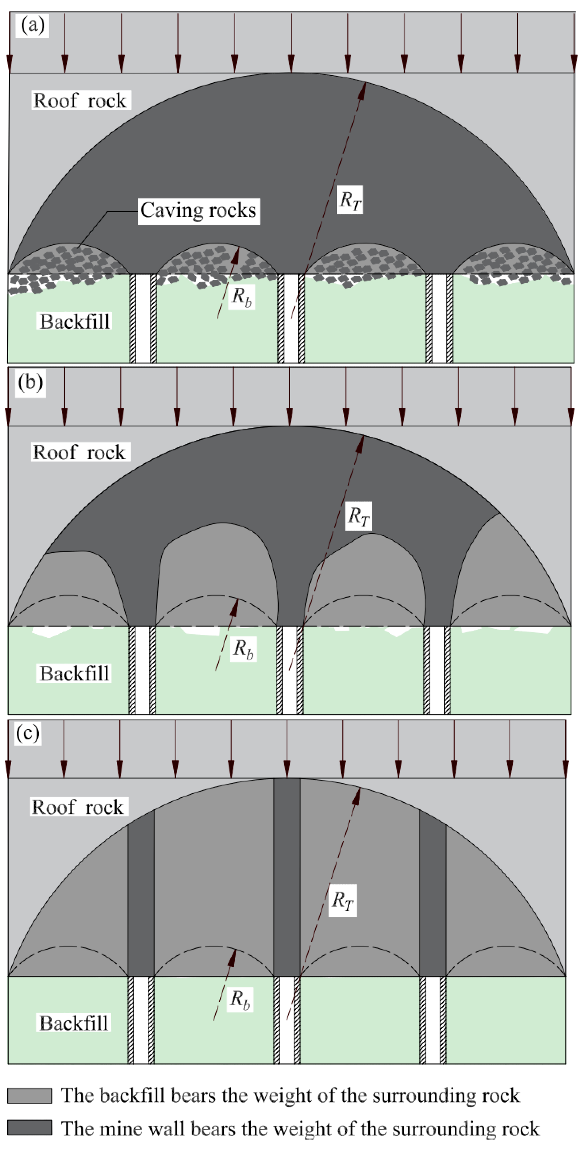
4.1. Initial Load on the Mine Wall under State I

Equations (15) and (16) show that the backfill–mine-wall system bears the total weight of the upper surrounding rock as
G T = ( R T h / 2 ) ( l b + l p ) γ r
where lb is the width of the backfill body (equal to the width of the stopes) and lp is the width of the isolated ore pillar.
When the backfill–mine-wall system is in State I, the force state of the backfill is the same as that of the unconnected roof, and the self-weight of the fallen surrounding rock in the upper part of the backfill, i.e., Gb1 is
G b 1 = ( R b h / 2 ) l b γ r
The vertical pressure (Fx1) on a single mine wall is the self-weight of the upper surrounding rock (Gw1) borne by the wall. Let the number of pressure-bearing mine wall is N, according to Gw1 = (GT Gb1)/N, combined with Equations (17) and (18) to obtain the calculation formula:
F x 1 = ( R T h / 2 ) ( l b + l p ) γ r ( R b h / 2 ) l b γ r N
The equation for calculating the initial lateral load at the top of the ore wall is determined from Rankine’s earth pressure theory and yields
q 1 = tan 2 ( 45 ° φ b / 2 ) G b 1 l b
where φ b is the friction angle within the backfill.
The total lateral pressure (Fy1) on the mine wall is
F y 1 = q 1 h + 1 2 λ γ b h 2

4.2. Initial Load on the Mine Wall in State II

When the backfill–mine-wall system is in State II, the backfill bears the self-weight of the upper surrounding rock (Gb2) and is determined by the compressive strength of the backfill and the roof-contacted filling rate, which is calculated by the formula
G b 2 = η σ b l b
where σ b is the compressive strength of the backfill and η is the roof-contacted filling rate.
The vertical pressure on a single wall is generated by the wall bearing the self-weight of the upper surrounding rock, and according to Gw2 = (GT Gb2) /N and Equations (17) and (22), the formula for calculating Fx2 is obtained as follows:
F x 2 = ( R T h / 2 ) ( l b + l p ) γ r η σ b l b N
The initial lateral load (q2) at the top of the mine wall is
q 2 = tan 2 ( 45 ° φ b / 2 ) G b 2 l b
The total lateral pressure on the mine wall is given as
F y 2 = q 2 h + 1 2 λ γ b h 2

4.3. Initial Load on the Mine Wall under State III

When the backfill–mine-wall system is in State III, the upper load of the backfill–mine-wall system can be regarded as uniformly distributed, and the uniform load set is Q = GT/(lb + lp) , which can be obtained from Equation (17):
Q = ( R T h / 2 ) γ r
The backfill bears the self-weight of the upper surrounding rock, and substituting Equation (26) yields:
G b 3 = ( R T h / 2 ) l b γ r
The vertical pressure on a single wall is generated by the wall bearing the self-weight of the upper surrounding rock, and from Gw3 = Qlp/N and Equation (26), Fx3 is calculated as follows:
F x 3 = ( R T h / 2 ) l p γ r N
The initial lateral load (q3) at the top of the mine wall is
q 3 = tan 2 ( 45 ° φ b / 2 ) G b 3 l b
The total lateral pressure on the mine wall is
F y 3 = q 3 h + 1 2 λ γ b h 2

5. Stability Analysis of the Mine Wall and Stope Design

5.1. Calculation of Safety Factor

For the stability analysis of the mine wall, scholars have proposed various research methods, including the factor of safety solving, theoretical analysis, and numerical simulation [46,47,48]. Among them, the safety coefficient, as an assessment index of the mine wall stability, can quantitatively reflect the stability state of the mine wall and is practical and widely used. This paper uses the safety factor to measure the stability of the mine wall, and its calculation formula is the ratio of the critical load to the actual load [49]. When the safety coefficient of the mine wall is greater than 1, the mine wall can be considered to be in a stable state; when the safety coefficient is equal to 1, the mine wall is in a critical state; when the safety coefficient is less than 1, the mine wall is in a destabilized state.
According to the critical load on the mine wall shown in Equation (12) and the force on the mine wall under the different filling states in Section 4.1, Section 4.2 and Section 4.3, the formula for calculating the safety coefficient of the mine wall under different roof-contacted filling rates can be obtained. The corresponding safety coefficients (K1, K2, K3) of the mine wall under loading States I, II, and III are as follows:
K 1 = F x c r F x 1 = N ( 8 D π 6 A 2 - F y h 4 A m g h 4 ) 2 π 2 h 2 A 2 [ r r ( l b + l p ) ( R T h / 2 ) l b r r ( R b h / 2 ) ]
K 2 = F x c r F x 2 = N ( 8 D π 6 A 2 - F y h 4 A m g h 4 ) 2 π 2 h 2 A 2 [ r r ( l b + l p ) ( R T h / 2 ) l b σ b t ]
K 3 = F x c r F x 3 = N ( 8 D π 6 A 2 - F y h 4 A m g h 4 ) 2 π 2 h 2 A 2 l p r r ( R T h / 2 )

5.2. Analysis of Factors Influencing the Stability of the Mine Wall

From calculation Equations (31)–(33) of the safety coefficient for the mine wall, it can be seen that the factors affecting the stability of the mine wall include three categories: one is the mechanical parameters of the ore body and the ore rock, including the modulus of elasticity E, the density of the mine wall γ p , the density of the roof γ r , the cohesion of the roof c r , and the angle of internal friction of the roof φ r . One category is the stope parameters (lp, lb, h, H0). The last category is the backfill parameters, including the roof-contacted filling rate and physical properties of the backfill ( φ b , γ b , σ b ). It is known that the mechanical parameters of the ore body and the overlying surrounding rock, the mining depth, and the height of the mine wall are determined by the geological conditions of the mine, and their values are generally fixed [49,50,51]. Therefore, the stability of the mine wall is mainly related to six factors: the width of the mine wall, the width of the stopes, the roof-contacted filling rate, the friction angle within the backfill, the density of the backfill, and the compressive strength of the backfill.
According to the mining sequence of the three-step method, the overlying surrounding rocks are supported by backfill after mining the room and pillar, and the stopes width and backfilling mechanics parameters ( σ b , γ b , φ b , etc.) can be considered as constant values when mining the isolated pillar. From the spatial and temporal sequence of mining, the width of the mine wall becomes the critical parameter for the safe mining of the isolated pillar. In addition, the effectiveness of the contact roof of the backfill is influenced by the nature of the backfill, the slurry concentration, and the shape of the roof. Thus, the roof-contacted filling rate is often difficult to control precisely, and the actual rate tends to differ in different stopes.
Therefore, this paper analyzes the stability of the mine wall by taking the width of the mine wall and the roof-contacted filling rate as variables in conjunction with the engineering example.

5.3. Backfill Components

Currently, the Dongguashan Copper Mine employs a full tailings stope backfilling process, using tailings produced by the mine’s concentrator as the backfill material. The chemical composition of the tailings is shown in Table 1, and this is also the backfill material used in this study. To ensure that the backfill material achieves the required strength in the stope or minimizes dewatering, it is generally necessary to add cement and other binders to the tailings in a certain ash-to-sand ratio and mix them to prepare a backfill slurry of a certain concentration.
Research on stope backfilling technology aims to select appropriate backfill ratios and concentrations, employing economical dewatering methods and backfill wall structures to achieve the goals of safe mining and backfilling. Table 2 shows the strength of test blocks under different ash-to-sand ratios and concentration conditions, as well as the curing time [52]. Due to the varying degrees of force on the stope structure, its stress state also differs, necessitating matching backfill ratio requirements according to the different stress conditions. The test blocks with different ash-to-sand ratios in this study were able to harden normally, and the backfill strength meets the requirements of the mining method.

5.4. Mining Design Plan Based on Backfilling Method

The main ore body of Dongguashan is divided into several panels along the strike direction, with a span of 100 m for each panel. It is vital to leave isolated pillars between each pan area to achieve independent mining for each pan area in this mining method. Within each panel, the 18 m wide area is taken as the stopes along the vertical ore body trend in turn, and the room-stopes and the pillar-stopes are arranged alternately. The first four panels (50–58 lines) were identified, as shown in Figure 4.
Ore body mining is carried out in three steps. Firstly, the stopes (room stopes) are mined and filled according to the ‘interval mining’ principle. Secondly, the remaining stopes (pillar stopes) are returned to mine and backfill. Finally, after the mining and backfilling of the stopes on both sides of the isolated pillar are completed, the isolated pillar will be mined and filled to realize the full utilization of resources.

6. Results and Discussion

According to the measured data of Dongguashan Mine, the mining height is about 60 m, the mining depth is 700 m, the mining width is 82 m, the isolation column is 18 m, and the number of mine walls left in the single disk area is 2. After mining, the stopes are filled with complete tailing sand cemented backfill, and the compressive strength of the backfill is about 5 MPa. The physical parameters of the surrounding rock and backfill are shown in Table 3.

6.1. Theoretical Calculation

According to the actual measurement data of Donggua Mountain, the critical roof-contacted filling rate can be obtained by Equation (22), Equation (18), and Equation (27). That is, when the roof-contacted filling rate is lower than 6.36%, it is difficult for the backfill to bear the self-weight of the upper surrounding rock, and the surrounding rock will collapse, which is the same as the backfill without capping. The loading of the backfill–mine-wall system is State I. When the roof-contacted filling rate is kept at 6.36–74.49%, the backfill bearing the self-weight of the upper surrounding rock depends on the roof-contacted filling rate and the compressive strength of the backfill. The loading of the backfill–mine-wall system is State II. When the roof-contacted filling rate exceeds 74.49%, the backfill–mine-wall force is State III. According to Equations (31)–(33), when the other factors affecting the stability of the mine wall are constant, the correlation between the roof-contacted filling rate and the safety factor of the mine wall under different conditions of the mine wall width is shown in Figure 5.
As shown in Figure 5, the width of the mine wall is a significant factor affecting its stability, and the safety coefficient of the mine wall increases with the increase of the width of the mine wall. At the same wall width level, there is a “stepwise” variation law between the roof-contacted filling rate and the safety factor.
As can be seen from Figure 5, under the above factors, when the width of the wall is less than 2.5 m, and the roof-contacted filling rate is less than 20%, the safety factor of the wall is lower than the critical value of 1, and the wall is in a state of instability. Combined with the actual situation of the project, the fluidity of the backfilling material resulted in a significant change in the capping rate of the goaf. Therefore, to ensure the stability of the mine wall in the actual project, the safety factor of the mine wall needs to be maintained at a higher level. Further, considering the influence of resource recovery rate and wall stability factors, the 3 m wall reserved in the design of isolated pillar mining could meet the requirements of safe mining. In addition, from the variation of the safety coefficient and the filling cost of the stopes, the safety coefficient of the mine wall width of 3 m has a more significant incremental rate when the roof-contacted filling rate is in the range of 30% to 78.94%, which means better stability.

6.2. Numerical Simulation

In order to improve the accuracy of the theoretical calculation results, this paper uses FLAC3D software (5.0, ITASCA, Minneapolis, MN, USA) to simulate and verify them. A four-pan mining model was built to analyze the stresses at a mine wall width of 3 m. To improve the simulation accuracy and eliminate the influence of boundary conditions on the results, three times the excavation size was selected along the strike direction of the ore body, and five times the excavation size was selected in the vertical ore body strike direction. The unit size is selected for modeling in the direction of the front and back sides of the mine wall, and the model size is 1200 m × 300 m × 1 m. Furthermore, the cell division follows the stress concentration principle, and the study area grid is encrypted. The numbers of model cells and nodes are 41,094 and 58,703, respectively. According to the actual mining situation of Dongguashan Mine, the simulation includes the initial stress field, excavation and backfill of the stopes, and the whole process of isolated pillar mining. Mohr–Coulomb was chosen for this structural model, and the surrounding rock and backfill mechanical parameters were referred to in Table 1. Figure 6 shows the main stress clouds in the initial state after backfilling the goaf (when filling rate is 50%) and after mining the isolated pillar.
According to the theoretical calculation, the safety factor of the mine wall of a 3 m width is greater than the critical value when the roof-contacted filling rates(η) vary. Therefore, eight sets of roof-contacted filling rates were taken at 10% intervals for numerical simulation to analyze whether the stresses in the mine wall were within the allowable values. Figure 7 shows the main stress cloud of the mine wall under different roof-contacted filling rates.
As shown in Figure 4, when the roof-contacted filling rate is low, the surrounding rock collapses and forms a small plastic arch. This is because the material used for filling only bears the weight of the surrounding rock in the small plastic arch, resulting in minimal lateral force acting on the mine wall. Consequently, the force exerted on the wall of the mine, as depicted in Figure 7a, is mainly in the form of compressive stress. As the roof-contacted filling rate increases, the self-weight of the surrounding rock also increases, leading to enhanced support of the mine wall through lateral action. When the roof-contacted filling rate reaches 15%, the force exerted on the mine wall takes the form shown in Figure 7b. This force induces tensile stress near the end of the mine wall on the side of the filling body and the hollow area side of the mine wall in the middle of the tensile stress zone. The mine wall experiences a consistent situation of lateral bending damage stress. When the roof-contacted filling rate reaches 75%, the weight of the overlying peripheral rock on the filling-body–mine-wall system can be assumed to be uniformly distributed. At this point, Figure 7h displays the mine wall force exerted, with the tensile stress on the mine wall peaking at a maximum of 2.34 MPa. On the side close to the goaf, stress concentration zones appear at the top and bottom of the wall, and the stress value increases with the increase in the roof-contacted filling rate, and the maximum value is about 89.7 MPa.
According to the data measured by the mine, the mine wall’s tensile strength and compressive strength are 3.04 MPa and 104.5 MPa, respectively, and the maximum tensile and compressive stresses on the mine wall are smaller than the tensile and compressive strengths, respectively. At the level of the above factors, the mine wall is stable, which is consistent with the theoretical calculation results.

6.3. Field Test

According to the theoretical analysis and numerical simulation results, the mining design of the Dongguashan Copper Mine is reserved for 3 m of ore wall, and the backfill method is complete tailing sand colluvial filling. Influenced by the fluidity of the backfill, the effect of roof-contacted filling is better in some areas and worse after the backfilling of the stopes. According to the mine monitoring and statistical data, the overall roof-contacted filling rate of the stopes is maintained at about 40%. The formula for calculating the safety factor in State II of the backfill–mine-wall system can be used. Therefore, from the calculation of Equation (30), it can be obtained that the safety factor of the mine wall is about 5.41, which is much larger than the critical safety factor of the mine wall. Hence, the mine wall is stable under this design condition.
The theoretical analysis and numerical simulation results were used to mine the G6 isolated pillar of Line 50. After mining, the goaf contour was scanned using the CMS empty zone detection technology to evaluate the mining effect of the isolated pillar. Figure 8 shows the results of the goaf scanning.
As can be seen from Figure 8, the backfilling effect of the stopes on both sides of the isolated pillar is better, with the total roof-contacted filling rate higher than 40%. It is difficult to avoid the possibility that both sides of the mine wall have different degrees of over-mining, and the maximum span of the empty area reaches 14.8 m. However, the integrity of the empty area is acceptable; the mine wall on both sides did not bend significantly during the mining process, and the end is firmly connected to the surrounding rock. Meanwhile, the backfill remained intact after mining, with no significant area collapse or obvious roof deformation. In addition, the maximum value measured by the displacement meter of the mine wall was 32 mm, and the deformation was within the controllable range. Therefore, the field test shows that the mine wall is not damaged and has good stability, which is consistent with the theoretical calculation results.

7. Conclusions

This paper establishes the critical load calculation formula for the mine wall through theoretical derivation, discusses the load bearing of the backfill–mine-wall system under different filler jointing rates, and gives the calculation formula for the safety factor of the mine wall. The stability of the mine wall was analyzed by the example of the Dongguashan Copper Mine, and the calculation results were verified by numerical simulation and field tests. The main conclusions are as follows:
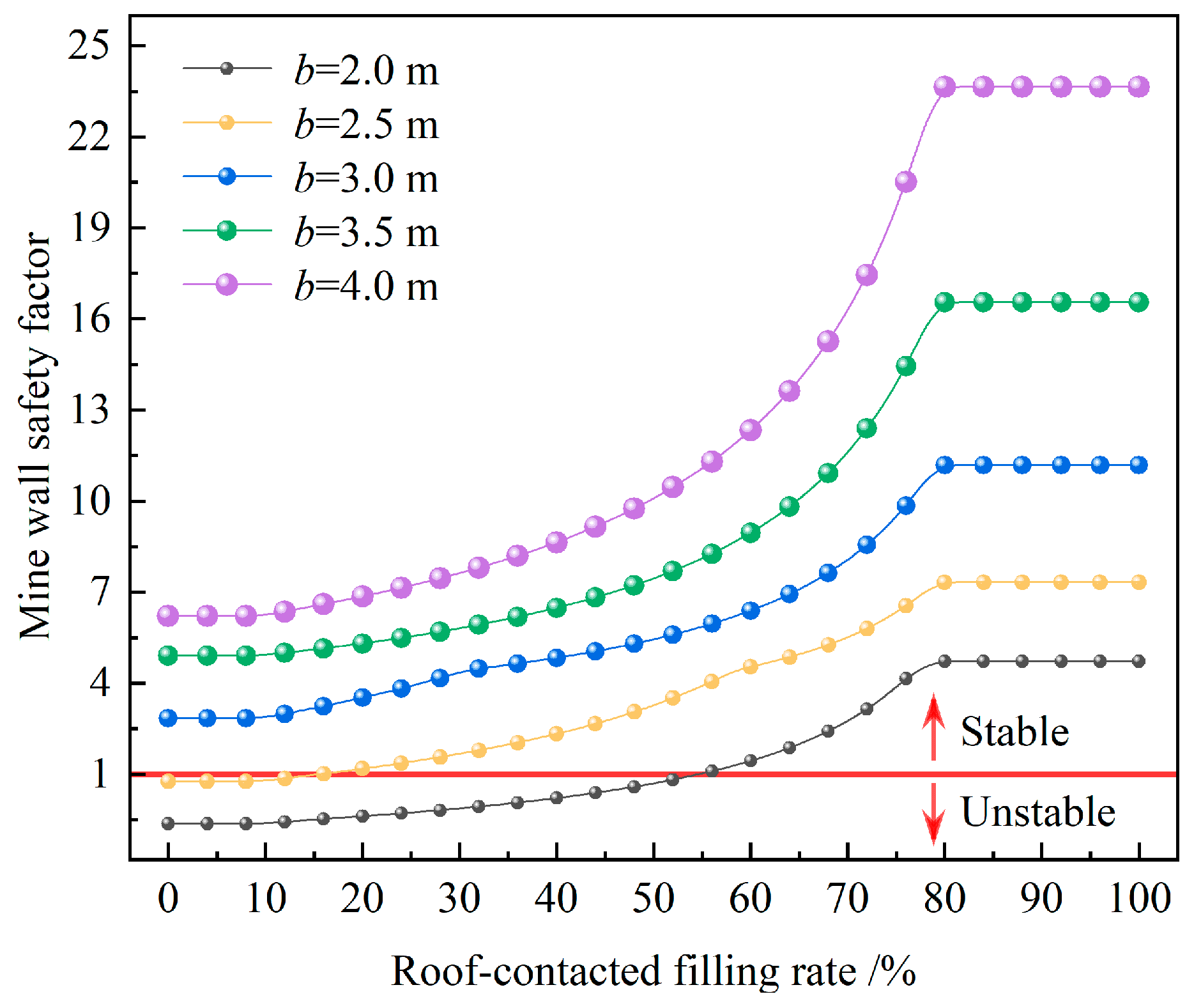
  • When the stopes parameters, rock, and backfill mechanical parameters are specific, the safety coefficient of the wall was calculated to vary with the roof-contacted filling rate under different wall width conditions; i.e., the safety coefficient of the wall and the roof-contacted filling rate under the same wall width showed a “trapezoidal” variation law. Considering the cost of stope backfilling and the variation pattern of the stope wall safety factor, when the roof-contacted filling rate is maintained within the range of 30% to 78.94%, the safety factor increases at a higher rate, resulting in better stope wall stability and higher overall benefits.
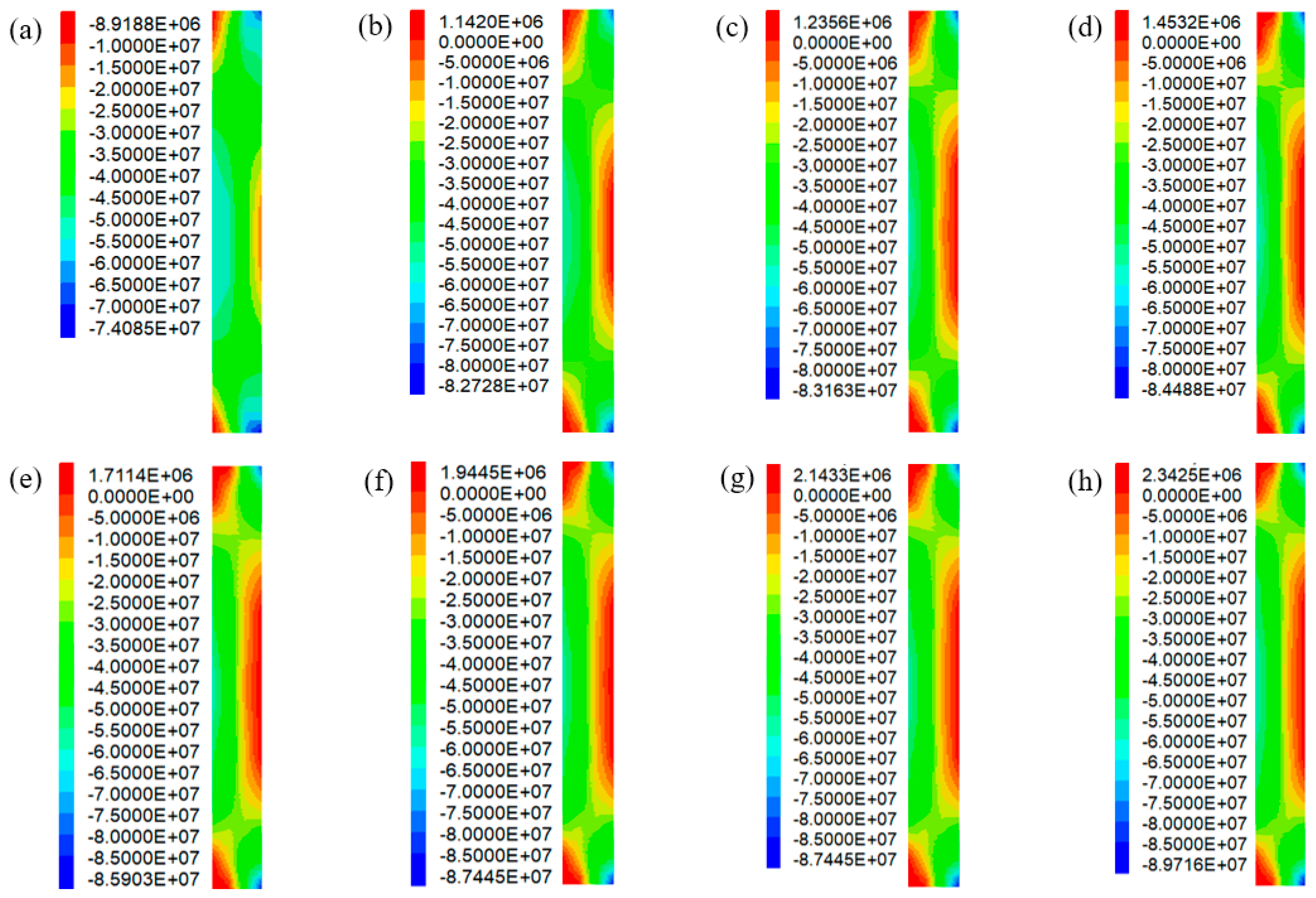
  • The numerical simulation of isolated pillar mining and the width of the mine wall was set to 3 m, which revealed that the lateral force on the wall increased with rising roof-contacted filling rates. This confirmed that the self-weight of the backfill-bearing rock grows with increased filling rates. Meanwhile, simulations with different roof-contacted filling rates showed stresses lower than measured values, for the 3 m wide wall, maximum tensile stress at 2.34 MPa, and maximum compressive stress at 89.7 MPa. This indicates the wall’s stability, aligning with theoretical calculations.
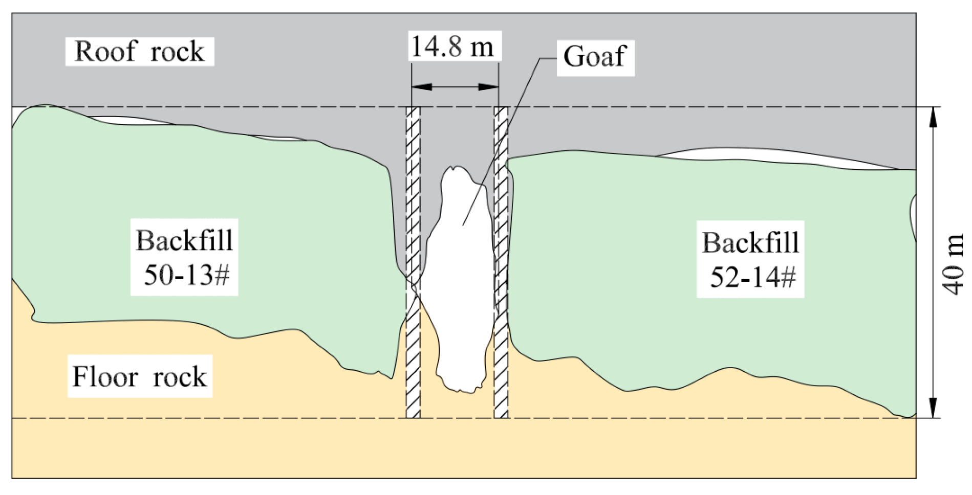
  • A mining field test was conducted on the G6 isolated mine pillar of Line 50. The final detection results showed that the mine wall with a width of 3 m was not damaged, the maximum displacement monitoring was 32 mm, and the deformation was within the controllable range. The field test is consistent with the theoretical calculation and numerical simulation. Consequently, the mine wall is stable.

Author Contributions

Conceptualization, J.G. and Y.Z.; methodology, W.Y.; validation, W.Z.; writing—original draft preparation, W.Y. and Y.Z.; writing—review and editing, W.Y., J.G. and W.Z. All authors have read and agreed to the published version of the manuscript.

Funding

This project was supported by the National Natural Science Foundation of China (52174140), Project supported by the Postgraduate Innovative Project of Central South University (2023XQLH103).

Acknowledgments

The team of authors express their gratitude to the editors and reviewers for valuable recommendations that have been taken into account to significantly improve the quality of this article.

Conflicts of Interest

Wanzhong Zhang was employed by the company Hongda Blasting Engineering Group Co., Ltd. The remaining authors declare that the research was conducted in the absence of any commercial or financial relationships that could be construed as a potential conflicts of interest.

References

  1. Wang, Y.M.; Wu, A.X.; Chen, X.S.; Yang, B.H.; Su, Y.D. New mining technique with big panels and stopes in deep mine. Trans. Nonferr. Metal. Soc. 2008, 18, 183–189. [Google Scholar] [CrossRef]
  2. Yu, W.; Zhai, S.; Gao, Q. Stability evaluation indexes of deep stope pillar and roadway surrounding rock. Disaster. Adv. 2012, 5, 120–126. [Google Scholar]
  3. Chen, S.H.; Zhang, Z.H. Determination of coal pillar width and support parameters in deep coal mines—A case study. J. Test. Eval. 2018, 47, 3160–3173. [Google Scholar] [CrossRef]
  4. Tuncay, D.; Tulu, I.B.; Klemetti, T. Re-analysis of abutment angle method for moderate and deep cover retreat room and pillar mines and investigation of loading mechanics using finite volume modeling. Rock Mech. Rock Eng. 2021, 54, 3447–3468. [Google Scholar] [CrossRef]
  5. Kongar-Syuryun, C.B.; Kovalski, E.R. Hardening backfill at potash mines: Promising materials regulating stress-strain behavior of rock mass. Geologiya I Geofizika Yuga Rossii. 2023, 13, 177–187. [Google Scholar]
  6. Li, Y.L.; Lu, B.; Yang, R.S.; Lin, H.; Xu, B.; Wang, S.S.; Liu, C.H. Coal mining technology and typical engineering cases of coal mining by continuous mining with coal-filled colluvial filling. J. Coal. 2022, 47, 1055–1071. [Google Scholar]
  7. Kovalski, E.R.; Kongar-Syuryun, C.B.; Petrov, D.N. Challenges and prospects for several-stage stoping in potash minining. Sustain. Dev. Mt. Territ. 2023, 15, 349–364. [Google Scholar] [CrossRef]
  8. Li, C.; Zhou, J.; Armaghani, D.J.; Li, X. Stability analysis of underground mine hard rock pillars via combination of finite difference methods, neural networks, and Monte Carlo simulation techniques. Undergr. Space 2021, 6, 379–395. [Google Scholar] [CrossRef]
  9. Ding, H.X.; Li, G.H.; Dong, X.; Lin, Y. Prediction of pillar stability for underground mines using the stochastic gradient boosting technique. IEEE Access 2018, 6, 69253–69264. [Google Scholar] [CrossRef]
  10. Jiang, S.Y.; Fan, G.W.; Li, Q.Z.; Zhang, S.Z.; Chen, L. Effect of mining parameters on surface deformation and coal pillar stability under customized shortwall mining of deep extra-thick coal seams. Energy Rep. 2021, 7, 2138–2154. [Google Scholar] [CrossRef]
  11. Basarir, H.; Sun, Y.; Li, G. Gateway stability analysis by global-local modeling approach. Int. J. Rock Mech. Min. Sci. 2019, 113, 31–40. [Google Scholar] [CrossRef]
  12. Carter, T.G. Guidelines for Use of the Scaled Span Method for Surface Crown Pillar Stability Assessment. Available online: https://static.rocscience.cloud/assets/verification-and-theory/CPillar/Trevor_Carter_2014.pdf (accessed on 26 June 2024).
  13. Qin, X.S.; Cao, H.; Wang, Z.X.; Zheng, Z.J. Analysis on safe thickness of the horizontal separation pillar in the upward horizontal slicing and filling method. IOP Conf. Ser. Earth Environ. Sci. 2021, 861, 052051. [Google Scholar] [CrossRef]
  14. Idris, M.A.; Saiang, D.; Nordlund, E. Stochastic assessment of pillar stability at Laisvall mine using artificial neural network. Tunn. Undergr. Sp. Technol. 2015, 49, 307–319. [Google Scholar] [CrossRef]
  15. Xia, K.Z.; Chen, C.X.; Liu, X.T.; Liu, X.M.; Yuan, J.H.; Dang, S. Assessing the stability of high-level pillars in deeply-buried metal mines stabilized using cemented backfill. Int. J. Rock Mech. Min. Sci. 2023, 170, 105489. [Google Scholar] [CrossRef]
  16. Fakhimi, A.; Hosseini, O.; Theodore, R. Physical and numerical study of strain burst of mine pillars. Comput. Geotech. 2016, 74, 36–44. [Google Scholar] [CrossRef]
  17. Li, Q.H.; Li, J.K.; Wang, Z.Q.; Li, K.X.; Zhang, C.Z. Study on coal pillar size design based on non-integral contact structure of coal and rock under static and dynamic loads. Front. Mater. 2021, 8, 721713. [Google Scholar] [CrossRef]
  18. Kortnik, J.; Nwaubani, S.; Kos, A. High safety pillars stability control using EL beam displacement sensors in Lipica II quarry. Acta Geotech. Slov. 2014, 11, 41–48. [Google Scholar]
  19. Waclawik, P.; Ptacek, J.; Konicek, P.; Kukutsch, R.; Nemcik, J. Stress-state monitoring of coal pillars during room and pillar extraction. J. Sustain. Min. 2016, 15, 49–56. [Google Scholar] [CrossRef]
  20. Walton, G.; Diederichs, M.; Punkkinen, A.; Whitmore, J. Back analysis of a pillar monitoring experiment at 2.4 km depth in the Sudbury Basin, Canada. Int. J. Rock Mech. Min. Sci. 2016, 85, 33–51. [Google Scholar] [CrossRef]
  21. Das, A.J.; Mandal, P.K.; Bhattacharjee, R.; Tiwari, S.; Kushwaha, A.; Roy, L.B. Evaluation of stability of underground workings for exploitation of an inclined coal seam by the ubiquitous joint model. Int. J. Rock Mech. Min. Sci. 2017, 93, 101–114. [Google Scholar] [CrossRef]
  22. Hauquin, T.; Gunzburger, Y.; Deck, O. Predicting pillar burst by an explicit modelling of kinetic energy. Int. J. Rock Mech. Min. Sci. 2018, 107, 159–171. [Google Scholar] [CrossRef]
  23. Zhang, S.R.; Qiu, S.L.; Jiang, Q.; Jia, L.X.; Li, S.J.; Xie, Z.K. Effect of fully-grouted bolts on the failure behaviors of mine pillars: Insights from block-based FDEM modeling. Constr. Build. Mater. 2024, 419, 135468. [Google Scholar] [CrossRef]
  24. Sinha, S.; Walton, G. Investigation of pillar damage mechanisms and rock-support interaction using Bonded Block Models. Int. J. Rock Mech. Min. Sci. 2021, 138, 104652. [Google Scholar] [CrossRef]
  25. Ahmad, M.; Al-Shayea, N.A.; Tang, X.-W.; Jamal, A.; Al-Ahmadi, H.M.; Ahmad, F. Predicting the pillar stability of underground mines with random trees and C4.5 decision trees. Appl. Sci. 2020, 10, 6486. [Google Scholar] [CrossRef]
  26. Mohanto, S.; Deb, D. Prediction of Plastic Damage Index for Assessing Rib Pillar Stability in Underground Metal Mine Using Multi-variate Regression and Artificial Neural Network Techniques. Geotech. Geol. Eng. 2020, 38, 767–790. [Google Scholar] [CrossRef]
  27. Du, X.; Feng, G.; Zhang, M.; Wang, Z.; Liu, W. Influence of backfilling rate on the stability of the “backfilling body-immediate roof” cooperative bearing structure. Int. J. Min. Sci. Techno 2022, 32, 1197–1206. [Google Scholar] [CrossRef]
  28. Das, A.J.; Mandal, P.K.; Paul, P.S.; Sinha, R.K.; Tewari, S. Assessment of the strength of inclined coal pillars through numerical modelling based on the ubiquitous joint model. Rock Mech. Rock Eng. 2019, 52, 3691–3717. [Google Scholar] [CrossRef]
  29. Huang, Z.G.; Dai, X.G.; Dong, L.J. Buckling failures of reserved thin pillars under the combined action of in-plane and lateral hydrostatic compressive forces. Comput. Geotech. 2017, 87, 128–138. [Google Scholar] [CrossRef]
  30. Wang, X.R.; Guan, K.; Yang, T.H.; Liu, X.G. Instability mechanism of pillar burst in asymmetric mining based on cusp catastrophe model. Rock. Mech. Rock. Eng. 2021, 54, 1463–1479. [Google Scholar] [CrossRef]
  31. Wang, T.T.; Yang, C.H.; Yan, X.Z.; Daemen, J.J.K. Allowable pillar width for bedded rock salt caverns gas storage. J. Petrol. Sci. Eng. 2015, 127, 433–444. [Google Scholar] [CrossRef]
  32. Reed, G.; McTyer, K.; Frith, R. An assessment of coal pillar system stability criteria based on a mechanistic evaluation of the interaction between coal pillars and the overburden. Int. J. Min. Sci. Technol. 2017, 27, 9–15. [Google Scholar] [CrossRef]
  33. Behera, B.; Yadav, A.; Singh, G.S.P.; Sharma, S.K. Numerical Modeling Study of the Geo-mechanical Response of Strata in Longwall Operations with Particular Reference to Indian Geo-mining Conditions. Rock Mech. Rock Eng. 2020, 53, 1827–1856. [Google Scholar] [CrossRef]
  34. Das, A.J.; Mandal, P.K.; Ghosh, C.N.; Sinha, A. Extraction of locked-up coal by strengthening of rib pillars with FRP—A comparative study through numerical modelling. Int. J. Min. Sci. Technol. 2017, 27, 261–267. [Google Scholar] [CrossRef]
  35. Jawed, M. Design of rhombus coal pillars and support for Roadway Stability and mechanizing loading of face coal using SDLs in a steeply inclined thin coal seam. Arab. J. Geosci. 2018, 11, 415–426. [Google Scholar] [CrossRef]
  36. Ma, Z.; Chen, C.; Liang, X.; Chen, A.; Song, W. Field and numerical investigation on the stability of coal pillars of gob-side entry driving with top coal. Arab. J. Geosci. 2020, 13, 1193. [Google Scholar] [CrossRef]
  37. Han, P.H.; Zhang, C.; Wang, W. Failure analysis of coal pillars and gateroads in longwall faces under the mining-water invasion coupling effect. Eng. Fail. Anal. 2022, 131, 105912. [Google Scholar] [CrossRef]
  38. Ibishi, G.; Genis, M.; Yavuz, M. Post-pillars design for safe exploitation at Trepca hard rock mine (Kosovo) based on numerical modeling. Geomech. Eng. 2022, 28, 463–475. [Google Scholar]
  39. Prakash, A.; Kumar, B.A.; Paul, A. MultiState assessment of post-mining effect on railway structures: A case study of Jharia Coalfield. J. Earth Syst. Sci. 2023, 132, 0154. [Google Scholar] [CrossRef]
  40. Kumar, S.; Sinha, R.K.; Jawed, M.; Murmu, S. Assessment of coal pillar strength under the influence of sand stowing in deep coal mines. Geotech. Geol. Eng. 2024, 42, 2815–2831. [Google Scholar] [CrossRef]
  41. Wang, J.; Huang, K.F.; Fu, J.X.; Song, W.D. Mechanical Behavior and Crack Evolution of Goaf Surrounding Rock with Different Roof-Contacted Filling Rates. Materials 2023, 16, 4435. [Google Scholar] [CrossRef]
  42. Guo, J.; Feng, Y.F. Cusp catastrophe theory analysis and width optimization on instability of pillar in deep mining. J. Saf. Sci. Technol. 2017, 13, 111–116. [Google Scholar]
  43. Zhao, K.; Yan, H.B.; Feng, X.; Wang, X.J.; Zhang, J.P.; Zhao, K. Stability analysis of pillar based on energy law. Chin. J. Theor. Appl. Mech. 2016, 48, 976–983. [Google Scholar]
  44. Guo, J.; Zhao, Y.; Zang, W.X.; Dai, X.G.; Xie, X.B. Stress analysis of mine wall in panel barrier pillar-stope under multi-directional loads. J. Cent. South Univ. (Sci. Technol.) 2018, 49, 3020–3028. [Google Scholar]
  45. Wu, A.C.; Shen, H.M.; Jiang, L.C.; Jiao, H.J.; Wang, Y.M. Arch effect of narrow and long filler and its effect on target strength. Chin. J. Nonferrous Met. 2016, 26, 648–654. [Google Scholar]
  46. Jiang, L.C.; Chen, P.; Wu, A.X. Self-stabilization effect of roof arch in mining area based on different filling jointing rates. Chin. J. Nonferrous Met. 2019, 29, 187–193. [Google Scholar]
  47. Ghasemi, E.; Ataei, M.; Shahriar, K. Prediction of global stability in room and pillar coal mines. Nat. Hazards 2014, 72, 405–422. [Google Scholar] [CrossRef]
  48. Zhang, J.X.; Huang, P.; Zhang, Q.; Meng, L.; Chen, Z.W. Stability and control of room mining coal pillars—Taking room mining coal pillars of solid backfill recovery as an example. J. Cent. South Univ. 2017, 24, 1121–1132. [Google Scholar] [CrossRef]
  49. Jessu, K.V.; Spearing, A.J.S. Direct strain evaluation method for laboratory-based pillar performance. J. Rock Mech. Geotech. 2019, 11, 860–866. [Google Scholar] [CrossRef]
  50. He, Y.; Huang, Q.; Wei, Y.; Du, J. Research on roof load transfer by passing coal pillar of working face in shallow buried closely multiple-seam. Minerals 2023, 13, 118. [Google Scholar] [CrossRef]
  51. Qiu, H.; Huang, M.; Weng, Y. Stability evaluation and structural parameters optimization of stope based on area bearing theory. Minerals 2022, 12, 808. [Google Scholar] [CrossRef]
  52. Kongar-Syuryun, C.; Klyuev, R.; Golik, V.; Oganesyan, A.; Solovykh, D.; Khayrutdinov, M.; Adigamov, D. Principles of Sustainable Development of Georesources as a Way to Reduce Urban Vulnerability. Urban Sci. 2024, 8, 44. [Google Scholar] [CrossRef]
Figure 1. Schematic diagram of mining of isolated ore pillars.
Minerals 14 00673 g001
Figure 2. Schematic diagram of the mechanics model of the mine wall.
Minerals 14 00673 g002
Figure 3. Load-bearing situation of the backfill–mine-wall system: (a) State I; (b) State II; (c) State III.
Minerals 14 00673 g003
Figure 4. Schematic of mining design in Dongguashan Copper Mine.
Minerals 14 00673 g004
Figure 5. Relationship between the safety factor and the roof-contacted filling rate.
Minerals 14 00673 g005
Figure 6. Main stress cloud: (a) initial state; (b) stopes backfilling; (c) isolated pillar mining.
Minerals 14 00673 g006
Figure 7. Main stress cloud of the mine wall under different roof-contacted filling rates: (a) η = 5%; (b) η = 15%; (c) η = 25%; (d) η = 35%; (e) η = 45%; (f) η = 55%; (g) η = 65%; (h) η = 75%.
Minerals 14 00673 g007
Figure 8. Illustration of the goaf of the G6 isolated pillar at line 50.
Minerals 14 00673 g008
Table 1. The chemical composition of tailings from Donggua Mountain.
Chemical CompositionSiO2Al2O3CaOMgOTFeSCu
Mass Fraction/%30.163.3714.925.8714.066.060.14
Table 2. Strength of test blocks under different cement–sand ratios and concentrations.
Test NumberFA/S RatioConcentration/%Strength/MPa
3 d7 d28 d60 d
1-11:4660.450.821.642.04
1-2680.571.011.712.45
1-3700.741.231.823.17
1-4720.771.491.983.66
1-5741.041.732.274.93
2-11:6660.300.740.901.45
2-2680.320.771.091.46
2-3700.350.801.171.47
2-4720.370.831.281.67
2-5740.390.861.381.98
3-11:8660.220.360.630.76
3-2680.240.380.660.79
3-3700.250.420.720.96
3-4720.280.470.830.98
3-5740.350.551.061.23
4-11:12660.210.270.380.52
4-2680.200.280.400.53
4-3700.20.300.430.57
4-4720.220.320.470.63
4-5740.230.340.510.67
The cement–sand ratio in the table is calculated based on the proportion of cement to tailings sand, with a tailings sand density (ρ) of 3.07 t/m3 and cement density (ρ) of 3.1 t/m3.
Table 3. Surrounding rock and backfilling mechanics parameters.
NameE/GPa μ c/MPa φ σ t ¯ /MPa γ /KN·m−3
Roof rock6.8350.32912.0050.281.7027.5
Mine wall6.5290.31211.6945.073.0432.2
Floor rock6.4870.25711.1440.022.2427.2
Backfill0.5700.2001.5535.700.1020.0
E is the effective modulus, μ is the friction coefficient, c is the cohesion, φ is the internal friction angle, σ t ¯ is the tensile strength, and γ is the density.
Disclaimer/Publisher’s Note: The statements, opinions and data contained in all publications are solely those of the individual author(s) and contributor(s) and not of MDPI and/or the editor(s). MDPI and/or the editor(s) disclaim responsibility for any injury to people or property resulting from any ideas, methods, instructions or products referred to in the content.

