Article

Effect of Fiber Types and Dosages on the Properties of Modified Aluminum Dross–Coal Gangue-Based Foam Filling Materials

by
Keyuan Yin
1,
Kai Wang
1,*,
Xiaoqiang Zhang
1,
Yulong Jiang
1 and
Shiyu Zhang
1,2
1
School of Mining Engineering, Taiyuan University of Technology, Taiyuan 030024, China
2
Holdings Coal Industry Group Co., Ltd., Datong 037000, China
*
Author to whom correspondence should be addressed.
Minerals 2025, 15(2), 106; https://doi.org/10.3390/min15020106
Submission received: 19 November 2024 / Revised: 30 December 2024 / Accepted: 15 January 2025 / Published: 22 January 2025
(This article belongs to the Special Issue Metallurgy Waste Used for Backfilling Materials)

Abstract

:
Fiber reinforcement offers a promising solution to improve the mechanical performance and durability of cement-based foam backfill (CFB), addressing critical issues such as brittleness and poor crack resistance under high-stress conditions. This study investigates the effects of polypropylene and polyacrylonitrile fibers, at varying contents and lengths, on the mechanical and flow properties of CFB. A series of experiments, including slump tests, rheology analysis, uniaxial compressive strength (UCS) tests, pore structure analysis, and scanning electron microscopy (SEM), were conducted to comprehensively evaluate fiber reinforcement mechanisms. The results show that increasing fiber content and length reduced fluidity due to fiber entanglement, while significantly enhancing mechanical properties through anchoring effects and network formation. After 28 days of curing, UCS increased by 208.2% with 2 wt% polypropylene fibers and 215.3% with 1 wt% polyacrylonitrile fibers (both at 6 mm length). Fiber-reinforced CFB demonstrated improved structural integrity and crack resistance, with failure modes transitioning from brittle to ductile. These findings highlight the potential of fiber-reinforced CFB to deliver durable, crack-resistant, and efficient mine backfill solutions, contributing to enhanced safety and sustainability in underground mining operations.

1. Introduction

The rapid growth of the global economy has driven increased demand for mineral resources, necessitating deeper and more intensive mining operations. However, these advancements have introduced significant challenges, including the accumulation of surface solid waste (e.g., tailings and waste rock) and the formation of large underground voids, known as goafs, which present critical risks such as ground subsidence, roof collapse, and seismic activity, thereby endangering both safety and operational efficiency [1,2]. Backfill mining methods have emerged as a reliable solution, enhancing resource recovery, mitigating surface waste accumulation, and improving underground stability [3,4,5].
Traditional backfill materials, composed primarily of cement and tailings sand, exhibit limitations such as excessive shrinkage during solidification due to high free water content. This shrinkage reduces stope roof contact and stability, hindering large-scale mining operations [6,7]. To address these limitations, cemented foam backfill (CFB) has been developed, which introduces a porous structure through controlled bubble incorporation. This innovation improves stope roof stability, absorbs blast-induced shock waves, and accommodates deformation [8,9,10]. However, the inclusion of air bubbles often reduces overall strength, restricting its application under high-load conditions and necessitating further reinforcement [10].
The integration of fibers into cementitious materials has been extensively explored in civil engineering to enhance mechanical performance, including toughness, crack resistance, and impact strength. Fibers such as polypropylene and glass have demonstrated significant potential in mitigating crack propagation and improving ductility, though often at the expense of reduced workability [11,12,13,14,15,16,17]. In mining, fiber-reinforced backfills have shown promise in reducing cement usage, improving ductility, and enhancing long-term durability under complex underground conditions [18,19,20,21,22,23,24]. Despite these advancements, a comprehensive understanding of how varying fiber parameters, such as type, length, and content, jointly influence the mechanical, rheological, and microstructural properties of cemented foam backfill (CFB) remains underexplored.
This study distinguishes itself by systematically investigating the effects of polypropylene and polyacrylonitrile fibers on a novel cemented foam backfill incorporating modified aluminum dross and coal gangue. Unlike conventional studies that focus on single fiber types or fixed dosages, this research evaluates multiple fiber parameters and their combined influence on the uniaxial compressive strength (UCS), rheological behavior, and microstructural integrity of foam backfill materials. Additionally, the innovative use of modified aluminum dross as a sustainable foaming agent not only transforms industrial waste into a functional material but also aligns with global efforts toward environmental sustainability. These advancements provide a novel framework for enhancing material performance and addressing key challenges in underground mining stability.
The findings presented in this study are based on the specific experimental conditions, including the use of polypropylene (PP) and polyacrylonitrile (PAN) fibers, and the modified aluminum foam–coal gangue matrix. While the results show promising improvements in compressive strength and crack resistance, these outcomes are specific to the tested materials and conditions. Further investigations under industrial-scale conditions are required before making any generalizations about their practical applicability.

2. Materials and Methods

2.1. Materials

Cemented foam backfill (CFB) samples were prepared from a composite mixture of modified aluminum dross, coal gangue, general-purpose Portland cement, and fiber reinforcement.

2.1.1. Aluminum Dross (AD)

The aluminum dross used in this study was sourced from an electrolytic aluminum plant in Taiyuan, China. The chemical composition of the aluminum dross is presented in Table 1, while its elemental composition is detailed in Table 2 [25,26]. As indicated by these tables, the primary component of the aluminum dross is alumina (Al2O3), accompanied by a significant amount of silica (SiO2). The high alumina content imparts excellent refractory properties, durability, and chemical stability to the material. Meanwhile, silica, which originates from mineral impurities during the aluminum oxidation process, enhances the mechanical properties of the dross. When used as a filling material, silica contributes to improved strength and compressive performance [27,28].

2.1.2. Ordinary Portland Cement (OPC)

The Ordinary Portland Cement (OPC) used in this study is classified as 42.5-grade and is widely employed in engineering applications due to its high early strength and excellent volumetric stability. To evaluate its influence on the experimental results, the chemical composition of the cement was analyzed using X-ray fluorescence (XRF) spectroscopy. X-ray fluorescence (XRF) spectroscopy for elemental analysis was conducted using an instrument from Olympus Corporation, Beijing, China. The detailed compound contents are presented in Table 3.
The results indicate that CaO and SiO2 are the primary components, accounting for 65.544% and 18.691% of the total composition, respectively. The high CaO content facilitates the formation of C3S and C2S, the main hydration products, which contribute significantly to the early strength and long-term durability of the cement matrix. SiO2, on the other hand, plays a critical role in providing structural strength. Additionally, moderate amounts of Al2O3 and Fe2O3 enhance the cement’s crack resistance and stability under various environmental conditions.
In terms of physical properties, the specific surface area of the OPC is approximately 350–380 m2/kg, ensuring fine particle distribution that improves hydration efficiency and workability. The bulk density is around 3.1 g/cm3, making it suitable for high-performance cementitious systems. The 28-day compressive strength exceeds 42.5 MPa, demonstrating its excellent mechanical properties.
In summary, the OPC used in this study serves as the primary binder, providing both early strength and enhanced durability. The high contents of CaO and SiO2 enable effective reactions with aluminum dross and coal gangue, further improving the overall performance of the backfill materials [29,30].

2.1.3. Coal Gangue (CG)

The coal gangue used in this study was sourced from the environmental protection building materials market. This market combines the demand for environmental protection with the sustainable growth trends of the construction materials industry. Its chemical composition is outlined in Table 4, while its elemental composition is detailed in Table 5. Predominantly composed of silica, the coal gangue exhibits strong siliceous characteristics, making it suitable for applications requiring such properties. This high silicon content renders CG samples particularly suitable for use as aggregates in construction materials. While the high silica content in coal gangue offers significant advantages for its use as aggregates in construction materials, including enhanced mechanical performance and chemical stability, potential risks must also be acknowledged. Notably, in alkaline environments, high silica content can trigger alkali–silica reactions (ASRs), which may compromise the long-term durability of the material. To mitigate these effects in practical applications, the incorporation of inhibitors or optimization of material proportions is recommended.
The coal gangue used in this study exhibits several notable physical characteristics that support its application in construction materials. The material has a bulk density of approximately 2.1 g/cm3, reflecting its compact structure and low porosity. These properties contribute to its high compressive strength, making it suitable for use as a load-bearing aggregate. The coal gangue particles demonstrate relatively low water absorption, ensuring durability under wetting–drying and freeze–thaw cycles, which are critical in harsh environmental conditions. In addition, the angular shape and rough surface of the particles enhance their interlocking capability within cementitious matrices, improving the overall mechanical performance of composites. The particle size distribution, which predominantly falls within the fine aggregate range, further facilitates its integration into cement-based materials. These observed physical properties, combined with its chemical composition, reinforce its potential as a sustainable and effective material for engineering applications.
The presence of alumina in the coal gangue may facilitate its broader application as a cement substitute or in other composite materials, particularly in engineering contexts with stringent strength requirements. The elemental analysis of the CG samples indicates that their high silicon content contributes to robust compressive properties, while the inclusion of aluminum and iron further enhances their mechanical strength, making them well suited for applications in the building materials sector.

2.1.4. Fiber

Two types of fibers, polypropylene (PP) and polyacrylonitrile (PAN), were chosen as reinforcement materials. Their key physical and mechanical properties are summarized in Table 6, highlighting their suitability for enhancing the performance of the composite.
Tensile Strength: The tensile strength of polyacrylonitrile fiber (759 MPa) is nearly double that of polypropylene fiber (368 MPa), indicating a superior load-carrying capacity under tensile loads. This characteristic makes polyacrylonitrile fiber more suitable for high-strength applications.
Young’s Modulus: The Young’s modulus of polyacrylonitrile fiber (4.89 GPa) is significantly greater than that of polypropylene fiber (3.66 GPa), indicating superior rigidity and resistance to deformation.
Elongation: The elongation properties of the two fibers exhibit minimal variation, with polyacrylonitrile fiber displaying a slightly higher elongation of 32%. Both fibers demonstrate commendable toughness, allowing them to withstand a degree of tensile deformation without failure.
Polypropylene fibers are widely utilized in concrete reinforcement, civil engineering materials, geotextiles, and various composite materials where weight reduction and specific toughness are required [31,32]. Owing to their excellent toughness and low density, polypropylene fibers exhibit notable performance in crack and impact resistance, making them particularly suitable for applications such as foundation reinforcement, tunnel support, and seepage prevention [33]. In contrast, polyacrylonitrile fibers offer superior strength and rigidity [34,35]. The selection of an appropriate fiber should be guided by specific engineering requirements and material performance criteria to ensure an informed decision. The lengths of polypropylene fibers used in this study were 3, 6, and 12 mm, while polyacrylonitrile fibers were available in lengths of 6 and 12 mm. SEM micrographs reveal distinct microscopic differences between the two fiber types. Polypropylene fibers exhibit relatively smooth surfaces, which facilitate better dispersion within the matrix, leading to a more uniform distribution. In contrast, polyacrylonitrile fibers display rougher surface morphologies, which may enhance interfacial bonding with the matrix but could also result in fiber entanglement, potentially affecting uniformity. These microstructural characteristics underscore the differing mechanisms through which the two fiber types contribute to the reinforcement of composite materials. The characteristics of both PP and PAN fiber materials are illustrated in Figure 1.

2.2. Preparation of Blowing Agent and CFB Sample

In the preliminary experiments, the utilization efficiency of aluminum dross (AD) was improved by modifying its nitrogen content and enhancing its volcanic dross activity [27]. In this study, aluminum dross was co-calcined with quicklime to optimize the performance of foaming agents, primarily by reducing the aluminum nitride (AlN) content. During the calcination process, AlN undergoes oxidation, producing alumina (Al2O3) and nitrogen gas (N2). The addition of quicklime enhances the denitrification efficiency by acting as a dispersing medium, while the formation of active phases such as C12A7 and CA2 improves the pozzolanic activity of the material. These characteristics contribute to the enhanced pore structure and mechanical properties of the foam backfill, making it suitable for engineering applications [27]. Raw AD was calcined with quicklime at a mass ratio of 0.4 under 950 °C, with a heating rate of 15 °C/min and a 2 h holding time (denoted as M2). After natural cooling, the material was ground in a planetary ball mill for 20 min and sealed for later use. The X-ray diffraction (XRD) patterns of the raw and calcined aluminum dross are shown in Figure 2.
Before Calcination: The XRD analysis of the raw material revealed prominent peaks corresponding to phases such as aluminum nitride (AlN), aluminum (Al), calcium carbonate (CaCO3), corundum (Al2O3), spinel (MgAl2O4), magnesium oxide (MgO), silicon (Si), silicon dioxide (SiO2), sodium chloride (NaCl), sphene (CaTiSiO5), calcium oxide (CaO), and titanium oxide (TiO2). AlN emerged as one of the primary phases, with its characteristic diffraction peak distinctly visible in the XRD pattern, indicating a substantial presence of aluminum nitride within the sample. The pronounced diffraction peak of aluminum suggests that a portion of the aluminum remained unoxidized prior to the calcination process.
After Calcination: Following calcination at 950 °C, the diffraction peak corresponding to AlN is significantly diminished or absent, indicating that AlN decomposes or undergoes chemical reactions during high-temperature calcination. AlN is known to readily react with oxygen or water at elevated temperatures, forming alumina (Al2O3) or related compounds. This accounts for the substantial reduction in the AlN peak in the XRD pattern after calcination, as well as the near disappearance of the aluminum peak, suggesting that aluminum underwent oxidation. At high temperatures, aluminum readily reacts with oxygen to form stable alumina (Al2O3), leading to a weakened or absent diffraction peak for aluminum and a pronounced alumina peak in the post-calcination XRD pattern. Additionally, calcite (CaCO3) present in the quicklime decomposes to form calcium oxide (CaO), which subsequently reacts with components in the aluminum dross, forming new calcium aluminate phases such as CaAl4O7 and calcium–aluminous oxide (Ca3Al2O6).
The use of 10% modified aluminum dross as a foaming agent in CFB has been identified as the optimal ratio for engineering applications, with a solid concentration of 75% in the fresh CFB mixture. In this study, the modified aluminum dross served as the foaming agent for producing FCFB samples, providing an effective balance between mechanical performance and practical workability.
During the preparation of fiber-reinforced cemented foam backfill (FCFB), polypropylene (PP) and polyacrylonitrile (PAN) fibers with lengths of 3, 6, and 12 mm were incorporated at contents of 0.5%, 1%, and 2%. Detailed mixing ratios are shown in Table 7. A “dry first, then wet mixing” method was employed to ensure uniform fiber dispersion, mixing the dry components for 3 min before adding water and continuing for another 3 min. The slurry was divided for slump and rheological tests, each repeated three times, while the remaining mixture was molded into 50 mm × 100 mm cylindrical samples for uniaxial compressive strength (UCS) testing at 3, 7, and 28 days. Samples were demolded after 24~48 h and cured at 20 ± 1 °C and 95% ± 1% humidity. The curing period before demolding was chosen to range between 24 and 48 h, depending on the specific conditions of the composite. This extended curing time was selected to ensure complete hydration and optimal strength development, particularly for the modified aluminum foam and coal gangue matrix, whose foaming characteristics necessitate additional time to achieve adequate strength. Three specimens per group were tested to ensure reliability, and the average results were recorded. Figure 3 shows the fresh CFB samples of different fiber types and contents, including (a) N, (b) PP3-1.0, (c) PP6-0.5, (d) PP6-1.0, (e) PP6-2.0, (f) PP12-1.0, (g) PAN6-0.5, (h) PAN6-1.0, (i) PAN6-2.0, and (j) PAN12-1.0.

2.3. Experimental Methods

A series of laboratory tests were conducted to examine the impact of fiber type, content, and length on the flowability and strength properties of CFB [36,37,38]. These experiments aimed to clarify how variations in fiber parameters influence the mechanical and rheological performance of CFB mixtures, providing insights into their behavior under different conditions.

2.3.1. Slump Test

Preliminary experimental data reveal that fiber type, content, and length significantly influence the strength and fluidity of CFB. To evaluate flow characteristics, the micro-cone slump test, adhering to the GB/T 50080 standard of the China National Standardization Committee, was employed [39]. This test utilized a micro-slump cone with dimensions of 150 mm in height, 100 mm in bottom diameter, and 50 mm in top diameter. Compared to standard methods, the micro-cone test offers material efficiency while maintaining reliability [36,39,40]. Each test was repeated thrice, with average values used for analysis.

2.3.2. Rheological Test

Rheometers play a crucial role in evaluating the rheological properties of backfill materials. In this study, the yield stress and thixotropy of CFB samples with different fiber types, contents, and lengths were measured using a rheometer. In this study, the yield stress and thixotropy of CFB samples with different fiber types, contents, and lengths were measured using a rheometer from Malvern Instruments, Shanghai, China. These parameters reveal the flow behavior and structural stability of CFB under varying conditions. The experimental data provide a foundation for understanding the influence of fiber reinforcement on CFB rheology and were recorded for comprehensive analysis.

2.3.3. UCS Test

Uniaxial compressive strength (UCS) tests were performed after the samples reached the specified curing age, following the GB/T17671-1999 standard. Uniaxial compressive strength (UCS) tests were performed after the samples reached the specified curing age, following the GB/T17671-1999 standard, using a testing machine from Instron Corporation, located in Taiyuan, China. A displacement loading method was applied at a rate of 1 mm/min, with stress and strain data recorded throughout the failure process. To ensure result reliability, three specimens were tested for each condition, and the average UCS values were calculated for further analysis.

2.3.4. Scanning Electron Microscopy Test

Post-UCS fractured samples were analyzed for microstructural characteristics. Central fragments were treated with anhydrous ethanol to halt hydration and dried at 50 °C. Scanning electron microscopy (SEM) analysis was performed using a TESCAN MIRA LMS SEM from TESCAN, Suzhou, China. Prepared samples were examined using a TESCAN MIRA LMS SEM under an accelerating voltage of 15 kV and a beam current of 10 nA. This provided insights into the micromorphology and fiber–matrix interactions.

2.3.5. Pore Test

According to the ASTM D4404-18 standard, the pore distribution of the cured foam filling material was measured using the Micromeritics AutoPore IV 9500 mercury porosimeter, manufactured in the United States. The instrument operates at a maximum pressure of 414 MPa, with a pore size detection range of 3 nm to 1000 μm. Post-UCS samples were taken away from the failure surface, soaked in isopropyl alcohol for 12 h to halt hydration, and dried to constant weight. Prepared specimens, cut into pieces smaller than 10 mm × 10 mm × 10 mm, were analyzed under controlled conditions. Factors such as sample size, pretreatment, surface tension, and contact angle during mercury intrusion influence the results. The relationship between mercury pressure and pore size is expressed as [41]
d p = 4 γ × cos θ p
γ: surface tension of mercury intrusion into pores; θ: contact angle between mercury and pore wall. In this experiment, γ = 485 dyn/cm, θ = 130°. d p refers to the pore diameter, a key metric used to characterize the distribution of voids within the material. p denotes the applied pressure during mercury intrusion.

3. Results and Discussion
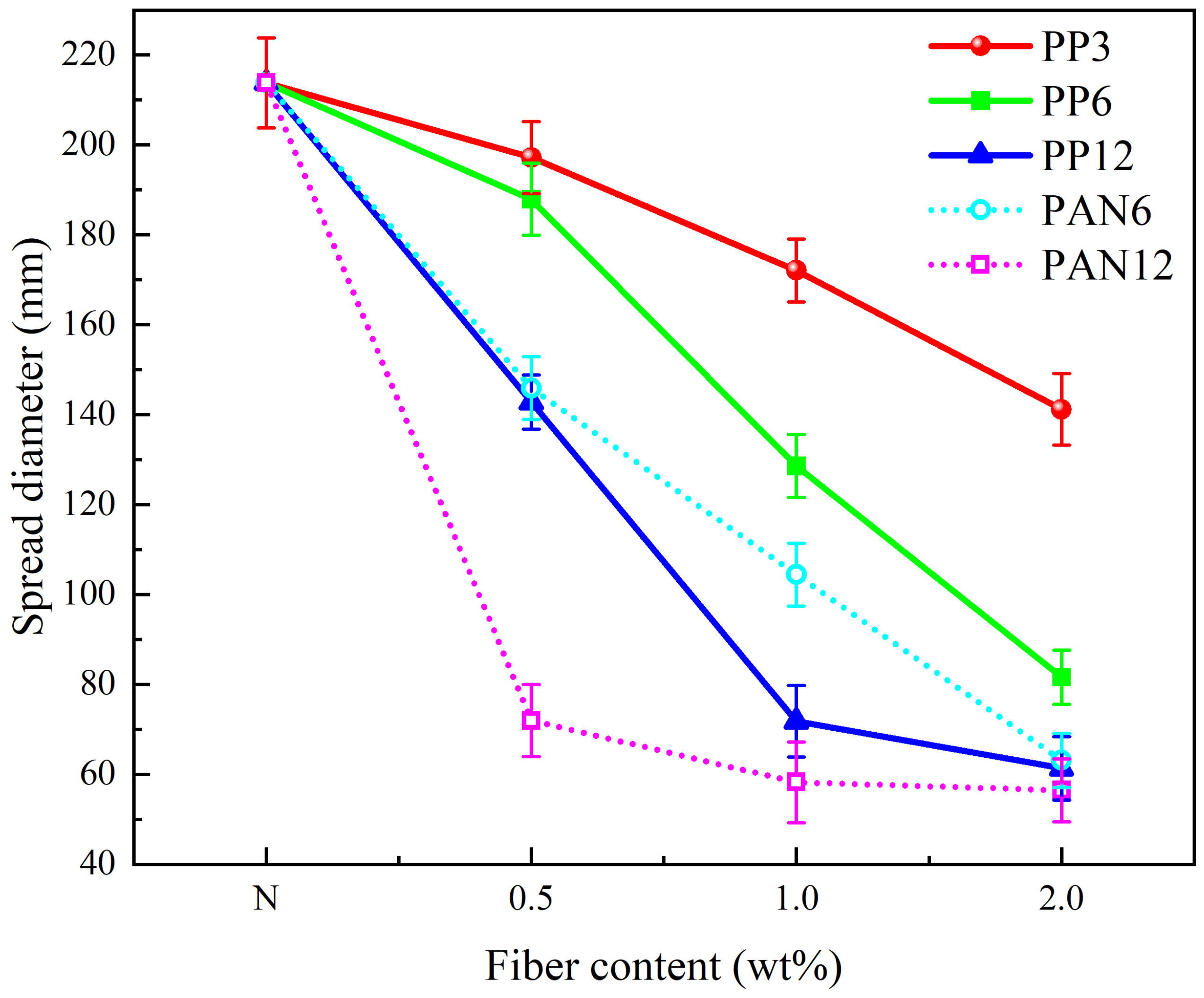
3.1. Slump Tests

The influence of fiber type, content, and length on the spread diameter fluidity of cemented foam backfill (CFB) is depicted in Figure 4. For CFB without fibers (N), the spread diameter is 213.8 mm. As polypropylene (PP) fiber content and length increase, the spread diameter decreases due to enhanced resistance from fiber entanglement and frictional interactions within the matrix. For example, the spread diameter for samples with 6 mm polypropylene fibers ranges from 187.9 mm for a content of 0.5 wt% (PP6-0.5) to 81.6 mm for a content of 2.0 wt% (PP6-2.0). Similarly, for samples with 6 mm polyacrylonitrile (PAN) fibers, the spread diameter ranges from 145.9 mm at 0.5 wt% (PAN6-0.5) to 60.1 mm at 2.0 wt% (PAN6-2.0).
Furthermore, increasing the fiber length also significantly reduces the spread diameter. For PP fibers, the spread diameter decreases from 172.1 mm at a 3 mm fiber length and 1.0 wt% content (PP3-1.0) to 71.8 mm at a 12 mm fiber length and 1.0 wt% content (PP12-1.0). For PAN fibers, the corresponding values range from 104.4 mm (PAN6-1.0) to 58.2 mm (PAN12-1.0). Notably, PAN fibers exhibit a more pronounced effect on the reduction in fluidity compared to PP fibers, particularly at higher fiber contents. This distinction is attributed to the higher tensile strength and surface friction of PAN fibers, which amplify the slurry’s internal resistance and restrict flow. Such behavior underscores the importance of selecting fiber types and parameters that balance fluidity and structural stability for specific backfill applications.
The addition of fibers significantly decreases the spread diameter of cemented foam backfill (CFB), primarily due to frictional resistance at the fiber–slurry interface [42]. As fiber content and length increase, resistance to slurry particle movement rises, reducing fluidity. Comparing the two fiber types, polypropylene (PP) fibers exert a relatively stable influence on flow characteristics, whereas polyacrylonitrile (PAN) fibers have a more pronounced impact, especially at higher contents, indicating their stronger effect on slurry behavior under these conditions.

3.2. Rheological Properties

3.2.1. Yield Stress

The influence of fiber type, content, and length on the shear stress–shear rate relationship of cemented foam backfill (CFB) is shown in Figure 5. Rheological test results reveal that these parameters significantly affect the material’s behavior.
Shear stress increases with higher fiber content and longer fiber length at a constant shear rate, demonstrating a strong dependence on fiber properties and their interactions within the matrix. For example, when polypropylene fibers of 6 mm length are added, the shear stress rises from 59.07 Pa at 0.5 wt% fiber content to 77.24 Pa at 2.0 wt%. Similarly, for polyacrylonitrile fibers of the same length, shear stress increases from 65.89 Pa to 98.83 Pa as the fiber content rises from 0.5 wt% to 2.0 wt%. This behavior is attributed to two primary factors. First, fibers become coated with the slurry matrix, enhancing interfacial frictional resistance [43]. Second, as fiber content and length increase, fiber entanglement becomes more pronounced, obstructing rotor movement during rheological tests and further raising shear stress. Additionally, longer fibers foster the formation of a network structure within the CFB, enhancing sample uniformity and continuity. As the network density grows with higher fiber content, its interaction with the rotor intensifies, contributing to the observed increase in shear stress [44].
Yield stress, a crucial indicator of the minimum shear stress needed for CFB to flow, was calculated using the Bingham model (Table 8). The data reveal that yield stress increases with fiber content, ranging from 10.85 Pa (PP6-0.5) to 24.25 Pa (PP6-2.0) for polypropylene fibers and from 19.37 Pa (PAN6-0.5) to 26.38 Pa (PAN6-2.0) for polyacrylonitrile fibers. This trend highlights the role of higher fiber content in enhancing interfacial friction and forming denser network structures within the matrix.
Additionally, yield stress was observed to rise with increasing fiber length, from 13.64 Pa (PP3-1.0) to 17.90 Pa (PP12-1.0). Longer fibers contribute to more pronounced network entanglement, which increases resistance to rotor movement during testing. These findings underscore the importance of carefully regulating fiber content and length to balance flowability and mechanical performance in CFB applications.

3.2.2. Apparent Viscosity

Figure 6 illustrates the relationship between the apparent viscosity of cemented foam backfill (CFB) and shear rate. The apparent viscosity decreases as the shear rate increases, consistent with the characteristics described by the plastic viscosity (η) in the Bingham model. With plastic viscosity values below 1 Pa·s, the slurry demonstrates low flow resistance, facilitating ease of processing and transport in industrial applications. Additionally, a lower plastic viscosity paired with increasing shear stress at higher shear rates aligns with the behavior of Bingham’s plastic model, indicating favorable fluidity.
In summary, the low plastic viscosity of CFB enhances its workability, as confirmed by all experimental groups in Table 8, where η remains under 1 Pa·s. However, fiber addition significantly increases apparent viscosity, with a gradual slowing in the rate of decrease as the shear rate rises. This phenomenon is attributed to the interaction and entanglement among fibers and between fibers and the rotor, which enhances structural resistance under shear.

3.3. Mechanical Properties

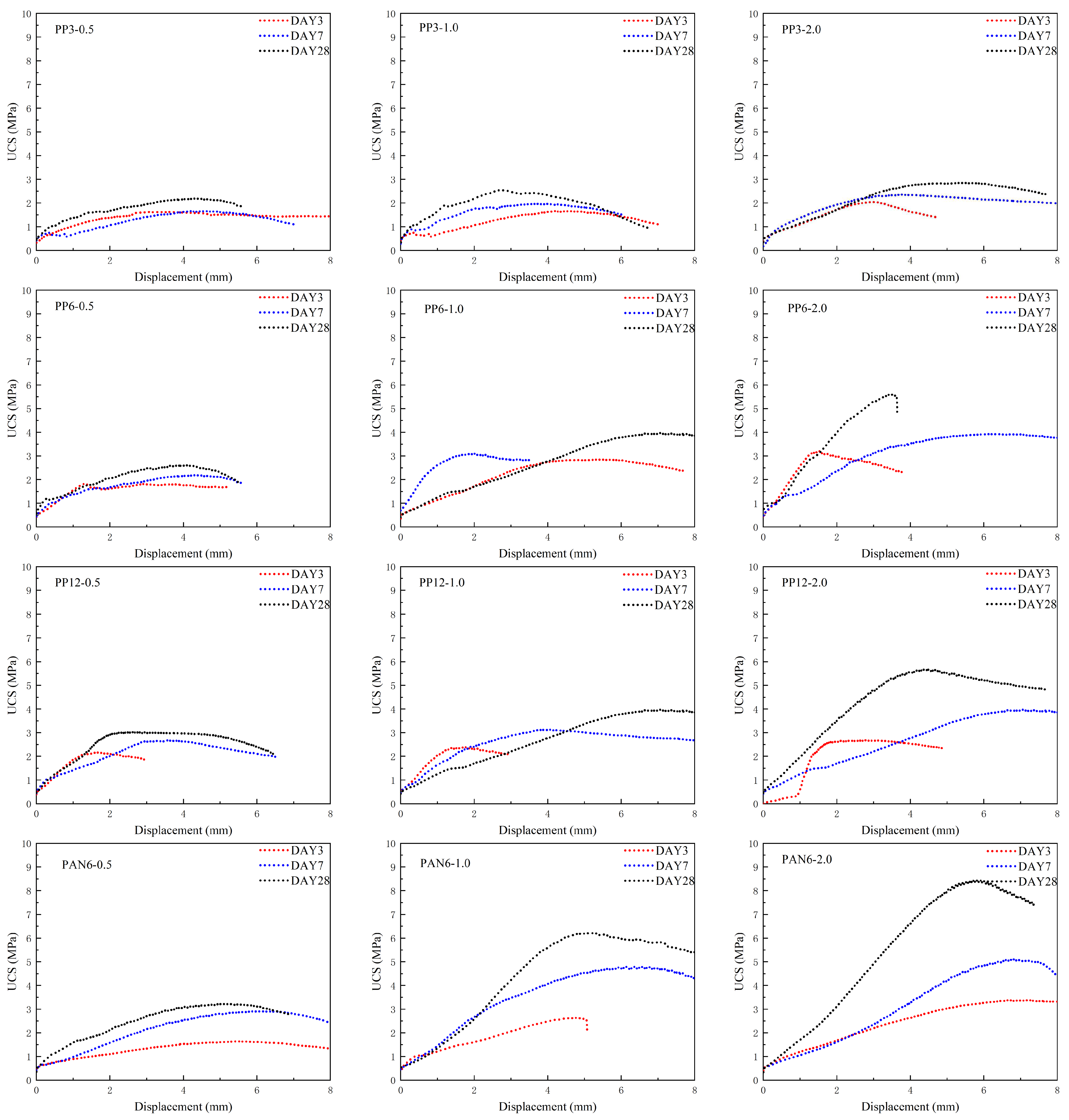
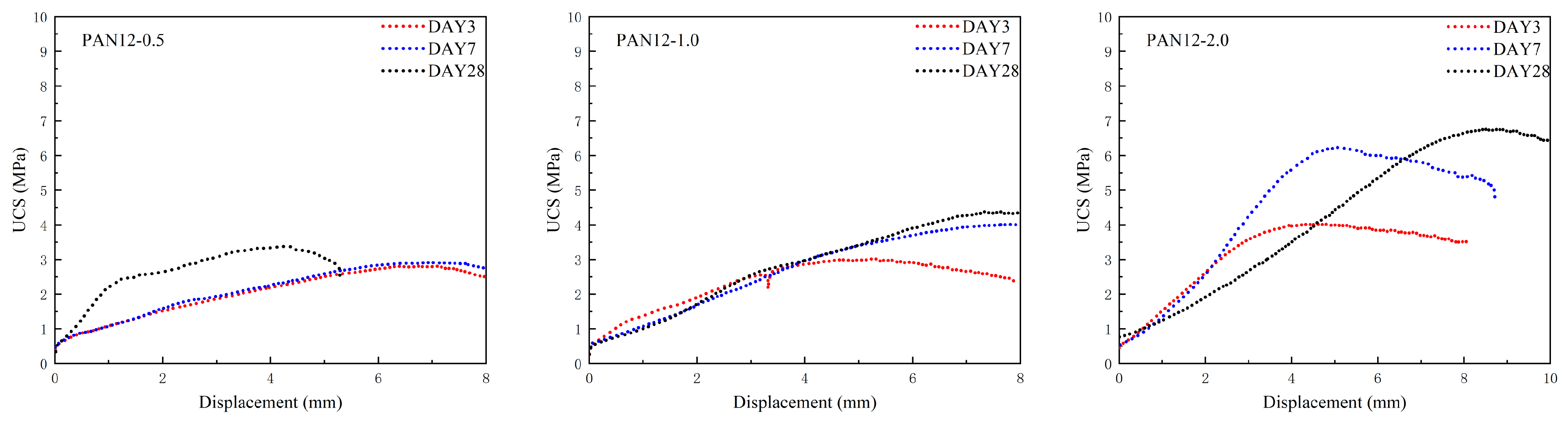
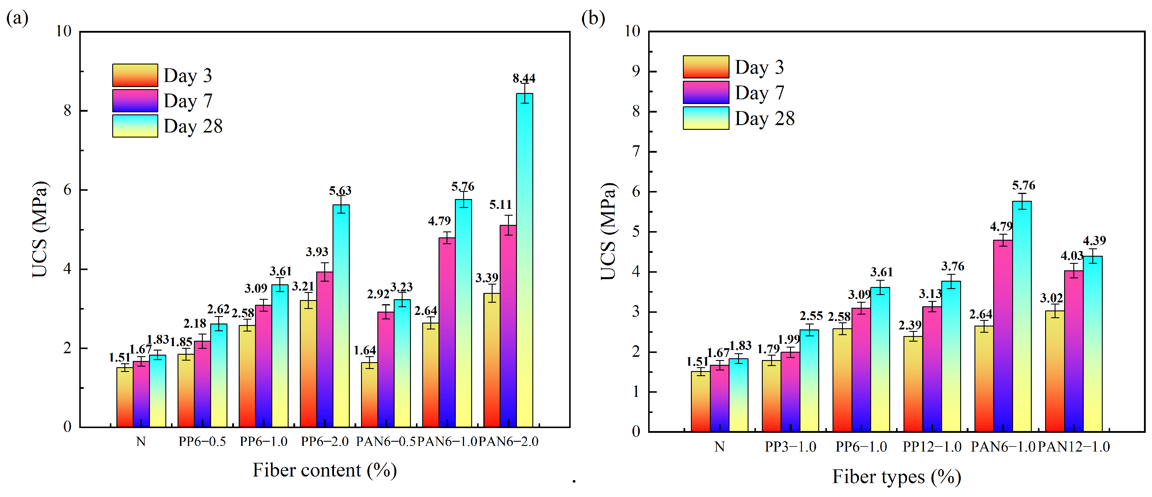
3.3.1. Uniaxial Compressive Strength Results

The strength and deformation behavior of cemented foam backfill (CFB) samples were examined at hydration ages of 3, 7, and 28 days. Figure 7 illustrates the force–displacement curves of fiber-reinforced CFB samples at these curing stages, providing insights into their mechanical response under compressive loading. The results reveal progressive changes in mechanical behavior, correlating with the evolution of hydration products over time. Figure 8a shows the relationship between UCS and fiber content, while Figure 8b highlights the effect of fiber type. For polypropylene (PP) fibers, UCS increased from 1.82 MPa (control group) to 5.63 MPa with 2 wt% PP fibers at 6 mm length, representing a 208% improvement. Polyacrylonitrile (PAN) fibers at 1 wt% and 6 mm length achieved the highest UCS of 5.75 MPa, corresponding to a 215% improvement. These results underscore the critical role of fiber reinforcement in mitigating brittleness and enhancing the load-bearing capacity of CFB.
Among all configurations, PAN fibers with 6 mm length and 2 wt% content exhibited the highest UCS, reaching 8.44 MPa, representing a 361% increase compared to the control group. However, this configuration showed extremely low fluidity, rendering it impractical for engineering applications and therefore excluded from further consideration.
The force–displacement curves in Figure 7 illustrate the deformation behavior of CFB samples at different curing ages. During early curing stages (3 days), UCS was limited by the initial formation of hydration products, providing only minimal structural support. By 7 days, the accumulation of C-S-H gels significantly enhanced the matrix integrity, leading to a marked increase in UCS. At 28 days, hydration reactions were nearly complete, and UCS reached its peak. Fiber-reinforced samples demonstrated superior performance compared to unreinforced controls, with PP6-2.0 and PAN6-1.0 samples showing UCS improvements of 208.2% and 215.3%, respectively. This highlights the critical role of fiber anchoring and bridging effects in suppressing crack propagation and enhancing matrix stability.
Figure 8b further elucidates the impact of fiber length and content on UCS. Shorter fibers (6 mm) outperformed longer fibers (12 mm) due to their uniform distribution and lower aggregation risk. Moreover, UCS increased significantly with fiber content up to 1 wt%. However, a plateau was observed at 2 wt%, where excessive fiber content led to non-uniform distribution and diminished improvements.
The findings of this study align with Chen et al., 2018, who demonstrated the significant role of fibers in enhancing the UCS of tailings backfill. However, while Chen reported a 90% increase in UCS with PP fibers, this study revealed a more pronounced 215.3% improvement with PAN fibers [45]. This discrepancy may result from the superior strength and rough surface morphology of PAN fibers. Additionally, consistent with the dynamic hydration model proposed by Haruna et al., 2010, this study highlights the role of fiber-induced pore refinement in increasing matrix density and load-bearing capacity [46].
Notably, the synergistic optimization of fiber content and pore distribution identified in this study complements findings by Hu et al., 2019, on the critical role of pore microstructure in determining backfill material performance [47]. Furthermore, this research uniquely quantifies the relationship between fiber length and pore evolution, filling a gap in the current literature.

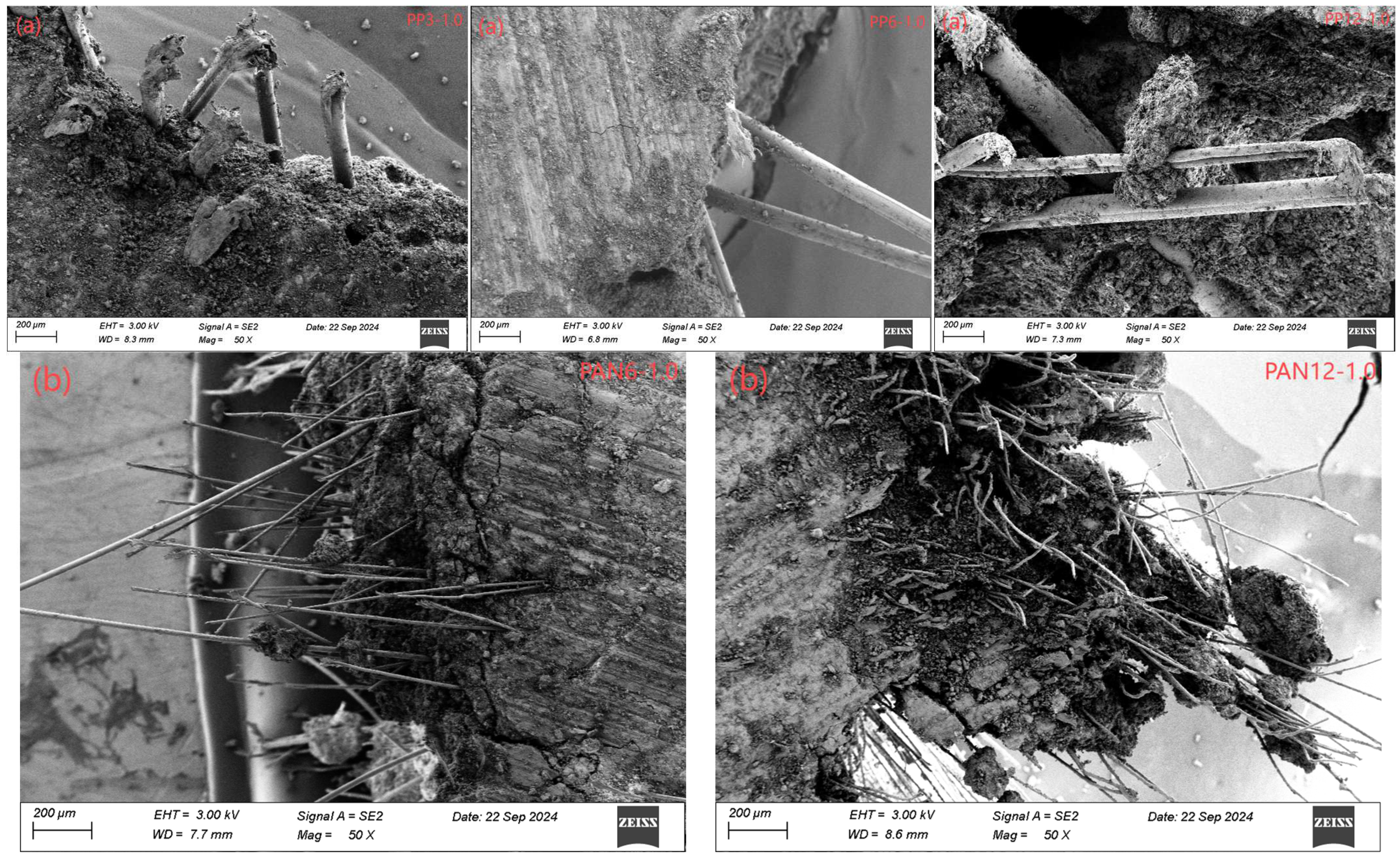
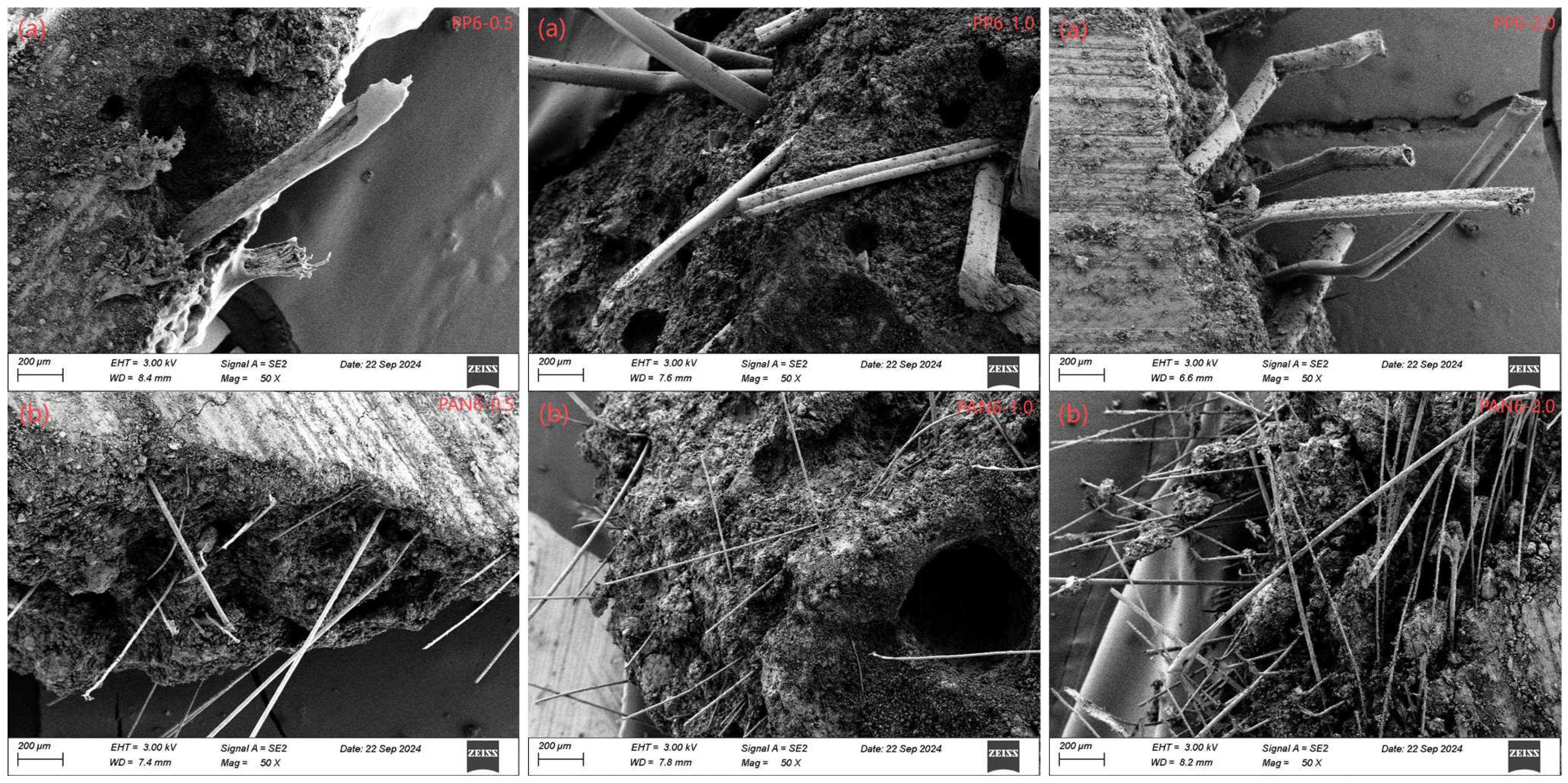
3.3.2. Analysis of Microstructure Behavior of Fiber-Reinforced CFB Samples

SEM images provide detailed insights into the microstructure of CFB samples, highlighting the mechanism of fiber reinforcement. The samples, cured for 28 days, were analyzed to examine the effects of fiber type, length, and content. Figure 9 presents the micromorphology of CFB samples reinforced with polypropylene fibers of 3 mm, 6 mm, and 12 mm, and polyacrylonitrile fibers of 6 mm and 12 mm. Figure 10 illustrates samples with polypropylene and polyacrylonitrile fibers at concentrations of 0.5 wt%, 1 wt%, and 2 wt%. The key findings are summarized below:
  • Microstructural Characteristics and Fiber–Matrix Interactions
PP fibers introduce coarse, uneven surfaces on the CFB matrix, which enhance interfacial friction and anchoring effects. In contrast, PAN fibers, characterized by their rougher surfaces and smaller cross-sectional diameters, form stronger interfacial bonds with the matrix, significantly improving stress transfer and structural stability. Both fiber types exhibit chemical inertness during hydration, reinforcing matrix continuity via interfacial friction [48].
2.
Fiber Pull-Out Mechanism
During compressive loading, fibers undergo pull-out behavior, dissipating applied stresses through interfacial friction and effectively delaying crack propagation. SEM images illustrate that PP fibers primarily exhibit sliding-induced wear, while PAN fibers demonstrate matrix penetration and robust anchoring effects. This bridging mechanism redistributes tensile stresses, reducing crack widths and transforming the failure mode from brittle to ductile.
3.
Impact of Fiber Content and Length
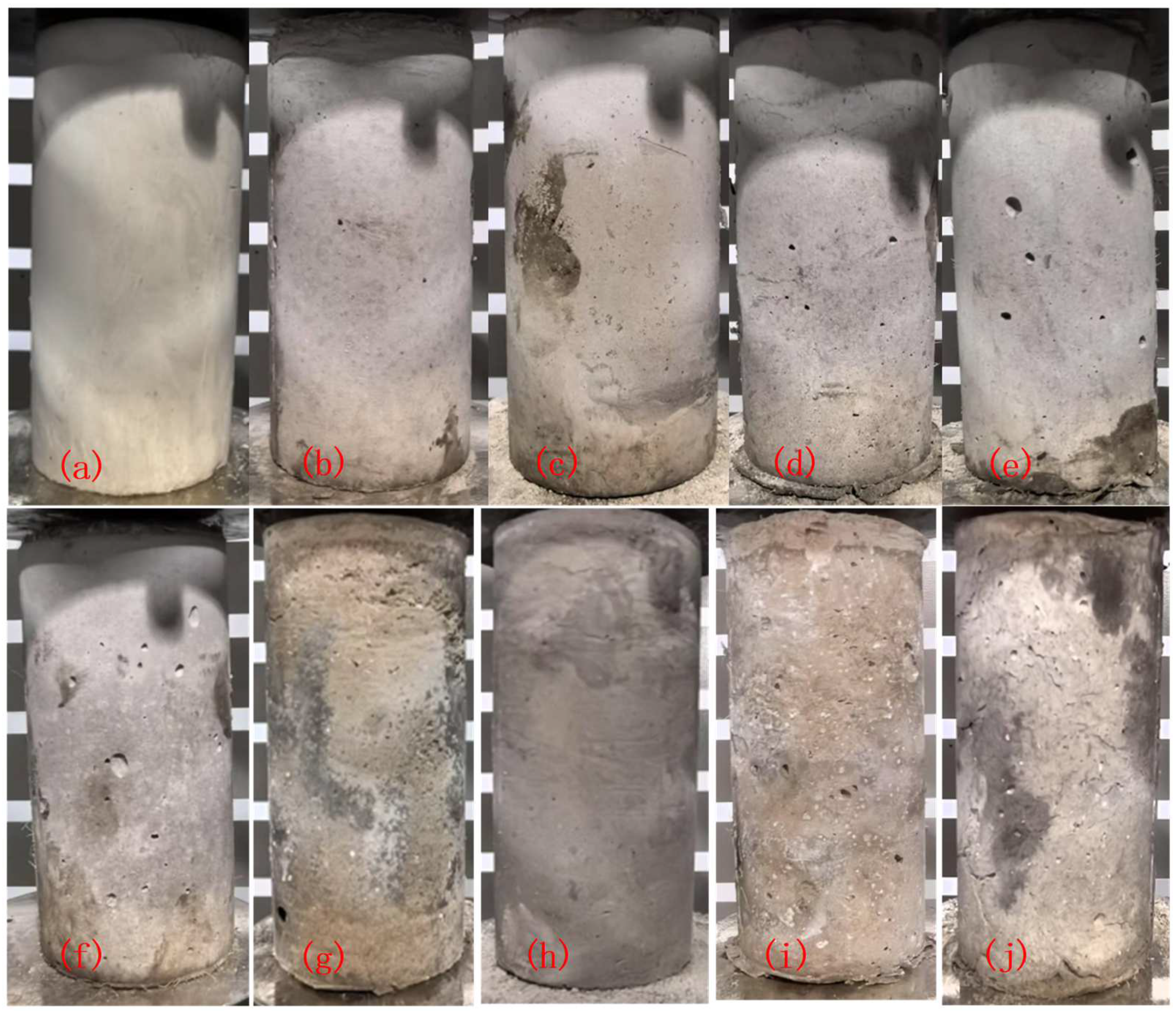
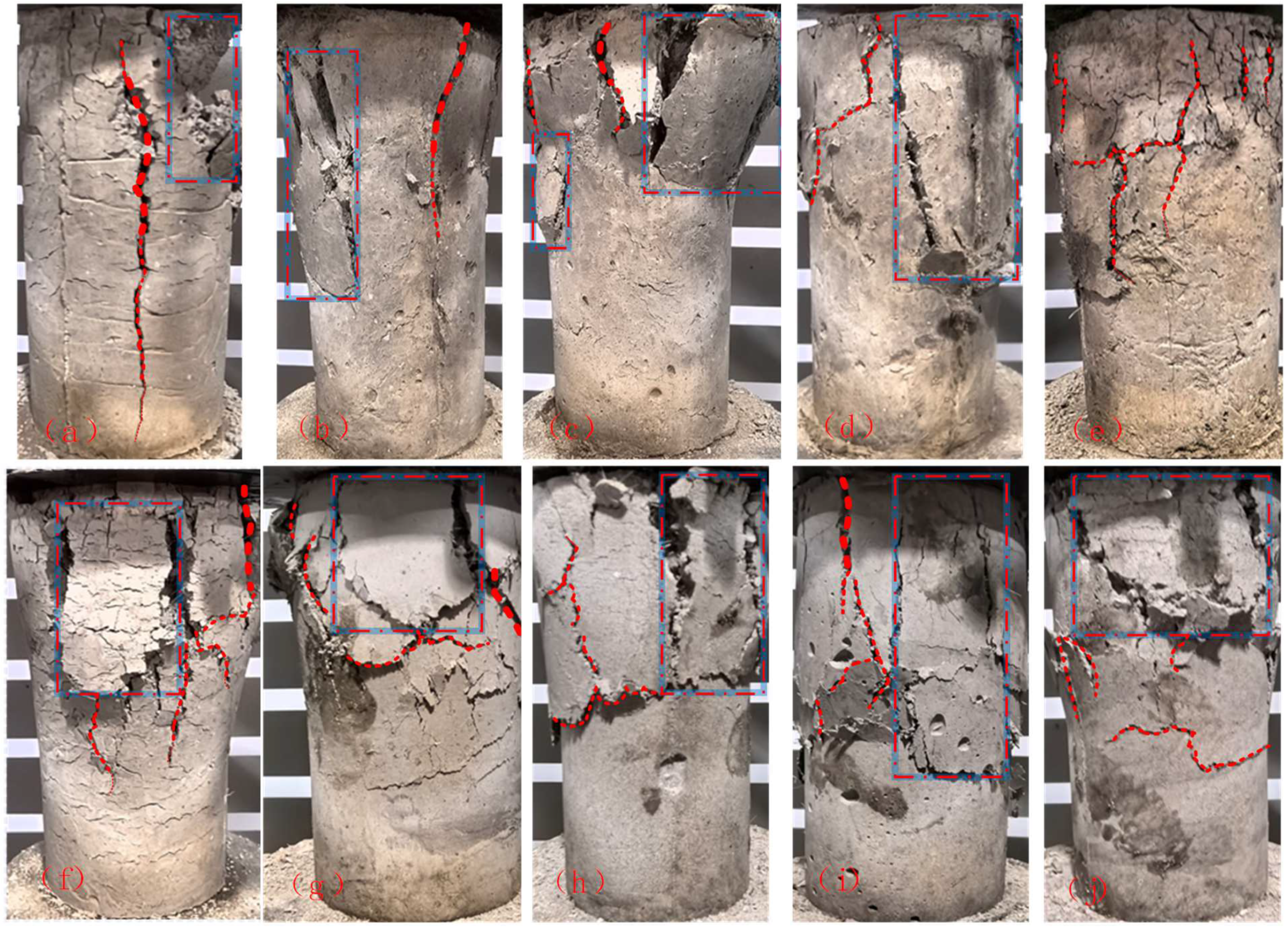
SEM observations reveal that increased fiber content enhances matrix connectivity, promoting energy dissipation during fracture. However, excessive fiber lengths (e.g., 12 mm) may lead to agglomeration, reducing uniform stress transfer and causing localized failures. Optimal performance was observed with 6 mm length and 2 wt% for PP fibers and 6 mm length and 1 wt% for PAN fibers.
SEM analysis provides critical insights into the fiber pull-out mechanism in cemented foam backfill (CFB). As shown in Figure 9 and Figure 10, polypropylene (PP) fibers generate coarse, uneven surfaces on the CFB matrix, enhancing interfacial friction and anchoring effects. Polyacrylonitrile (PAN) fibers, due to their rougher surface morphology and smaller cross-sectional diameter, establish a stronger interfacial bond with the matrix, further augmenting mechanical stability.
During the loading process, the fibers undergo a pull-out phenomenon, where the interfacial frictional force dissipates the applied stress, preventing sudden crack propagation. The SEM images reveal that PP fibers primarily exhibit sliding-induced wear at the fiber–matrix interface, while PAN fibers display surface abrasion and matrix penetration, indicating robust anchoring. The bridging effect of fibers reduces crack width, redistributing tensile stress across the matrix. This “bridging and anchoring synergy” transforms the failure mode from brittle fracture to a more ductile response, as evidenced by the gradual development of micro-cracks and delayed material failure.
The extent of fiber pull-out is influenced by fiber content and length. Higher fiber content increases matrix connectivity, while longer fibers enhance the energy dissipation capacity during fracture. However, excessive fiber length (e.g., 12 mm) can induce agglomeration, reducing the uniformity of stress transfer and leading to localized failure zones.
In the initial stages of CFB development, the impact of fibers on unconfined compressive strength (UCS) is minimal. This is attributed to the weak anchoring effect of the fibers during early hydration, which limits their contribution to overall performance. By 28 days, when hydration reactions are nearly complete, the interface friction between fibers and the hardened matrix increases significantly, enhancing the anchoring effect.
During loading and failure, fibers improve tensile and shear strength at crack tips, dissipating energy and reducing stress concentration. As loading progresses, micro-cracks form and extend, leading to gradual failure of the CFB sample.
As shown in Figure 8, the strength of the CFB increases with the incorporation of longer and more fibers. Observations of the surface hydration products of CFB (Figure 11) and their elemental composition (Figure 12) suggest that the superior strength performance of fiber-reinforced CFB, influenced by various fibers and their content, can be attributed to several factors.
During the initial stages of CFB preparation, the irregular distribution of fibers forms a network structure that prevents the sedimentation of larger particles within the slurry [49]. This network effect reduces material segregation and minimizes the volatilization of non-reactive water, thereby prolonging the hydration process. Sustained hydration enhances the structural integrity of the CFB, ultimately improving its strength.
Furthermore, preventing sedimentation contributes to a more uniform distribution of aggregates within the slurry, allowing them to function effectively as a skeletal framework and improving the overall strength of the sample. Additionally, from a microscopic perspective, while the inclusion of fibers generally increases the porosity of conventional backfill materials, this effect is relatively minor in foamed backfill materials due to their inherent characteristics.

3.3.3. Failure Mode

Figure 13 illustrates the failure modes of 10 specimen groups after 28 days of curing under compressive strength testing. The failure behavior of non-fiber-reinforced samples (N) revealed localized failure along the primary crack propagation path under loading. This resulted in poor structural continuity, as previously reported [50].
In contrast, the addition of fibers significantly altered the failure characteristics of the samples. Fiber reinforcement introduced anchorage effects that enhanced the linkage between fibers and the matrix. This “bridging effect” connected different regions of the CFB samples, redistributing the tensile and shear stresses to the matrix, which reduced the stress concentration at crack tips [43].
The random distribution of fibers formed a complex network structure within the matrix. This network, through anchorage and bridging effects, counteracted significant loads and improved the structural continuity and integrity of the samples. Before reaching the maximum anchorage force, the interactions prevented fiber slippage within the matrix, effectively transforming the failure mode of CFB from brittle to ductile [51].
Additionally, fiber type and content influenced the failure modes:
Polypropylene fibers (PP) exhibited superior flexibility, allowing the network to absorb and dissipate stress more effectively. Samples such as PP6-1.0 and PP6-2.0 showed delayed crack propagation and higher ductility.
Polyacrylonitrile fibers (PAN) demonstrated stronger interfacial bonding due to their rougher surface morphology. This improved the anchoring capability, leading to more cohesive failure modes in PAN6-1.0 and PAN6-2.0 samples.
These observations confirm that fiber reinforcement improves both the mechanical performance and failure behavior of FCFB samples, making them more suitable for practical engineering applications.

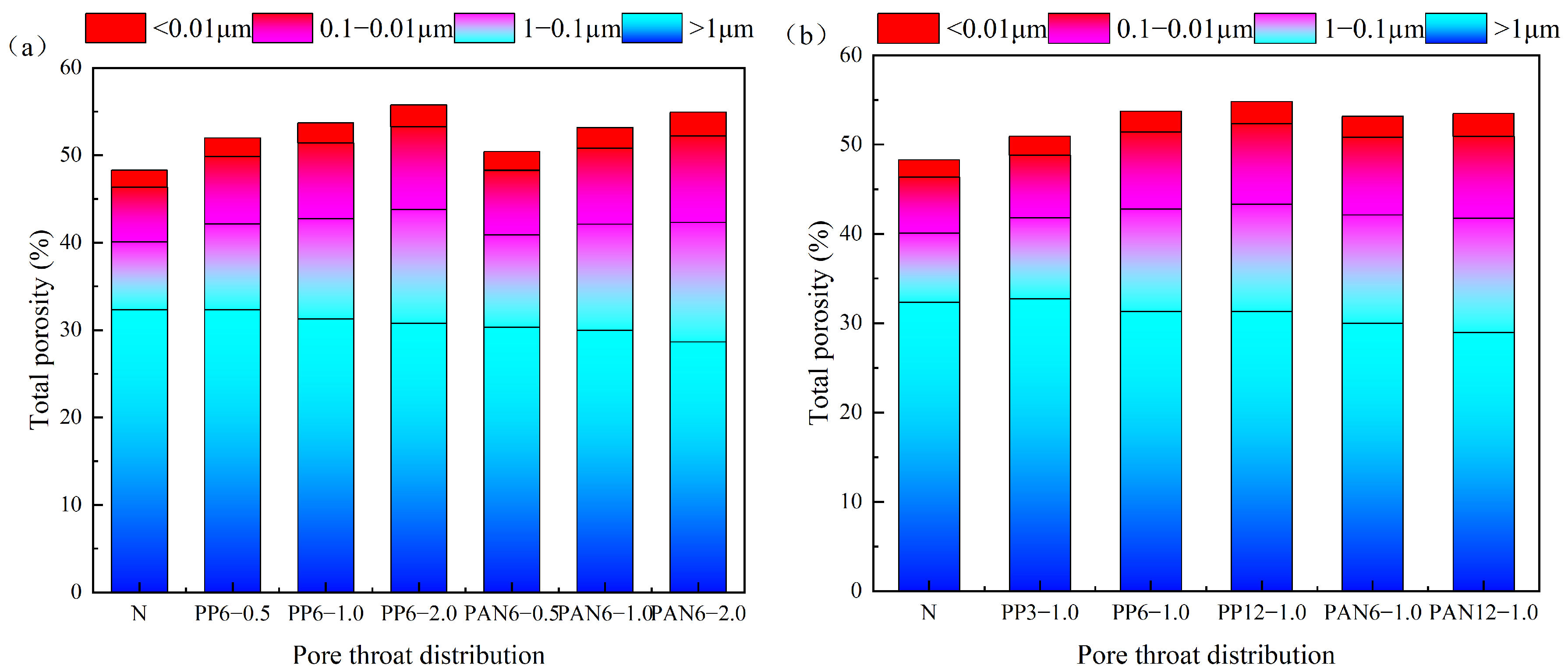
3.3.4. Pore Distribution

According to the literature, the compressive strength of backfill is influenced by both pore microstructure and hydration degree [41]. To investigate the mechanism by which foaming dose affects the strength of foamed backfill, the micro-pore structure of the 28-day solidified foamed backfill was analyzed. In this study, the pores were classified into four categories: (1) large pores (r > 1 μm); (2) capillary pores (1 μm–0.1 μm); (3) transitional pores (0.1 μm–0.01 μm); and (4) gel pores (r < 0.01 μm). The calculated results for each pore type are presented in Figure 14.
Figure 14a illustrates the porosity variations in CFB samples with different fiber contents, while Figure 14b presents the porosity changes in samples with varying fiber types. The results demonstrate significant differences in the pore characteristics between foamed backfill and ordinary backfill. Specifically, the primary pore size of ordinary backfill ranges from 0.01 to 1 μm, whereas foamed backfill exhibits a dominant pore size distribution between 1 and 500 μm. Moreover, larger pores are more prone to stress-induced damage, highlighting their susceptibility under load-bearing conditions.
Compared to the control group (N), the total porosity of specimens increased with higher fiber content. Gel pores, transitional pores, and capillary pores showed a rising trend, while macropore porosity decreased. This indicates that fibers effectively fill larger pores, reducing their size from >1 μm to smaller ranges (1 μm to 0.1 μm and 0.1 μm to 0.01 μm). Longer fibers were associated with a greater proportion of smaller-diameter pores. Notably, macropores did not increase, demonstrating that the matrix’s pore structure remained stable without deterioration.
The results show that total porosity increases with higher fiber content. When the fiber content reached 0.5 wt%, 1.0 wt%, and 2.0 wt%, the porosity of the polypropylene fiber-reinforced matrix increased by 3.41%, 5.17%, and 7.32%, respectively, while that of the polyacrylonitrile fiber-reinforced matrix increased by 2.01%, 4.48%, and 6.61%. This rise is primarily due to the formation of small bubbles during sample preparation, which are challenging to compact and remain trapped within the matrix.
Despite the increase in porosity, the overall mechanical properties of the CFB matrix were not significantly affected. Compared to the control group, the compressive strength still improved, indicating that the fibers’ reinforcing effect on mechanical properties outweighed the weakening impact of increased porosity.
Moreover, due to the hydrophobic nature of the surfaces of both polypropylene and polyacrylonitrile fibers, voids are created between the fibers and the binding surface of the matrix, resulting in pore formation during the curing process of the backfill. This phenomenon is further corroborated by the SEM images of CFB surfaces presented in Section 3.3.2. Analysis revealed that the effect is more pronounced with longer fibers, leading to the generation of more bubbles upon their addition. Consequently, when the fiber length was 12 mm, the porosity of the polypropylene and polyacrylonitrile fiber-reinforced samples increased by 7.32% and 6.61%, respectively, compared to the control group.
The pore distribution of CFB samples cured for 28 days was analyzed in conjunction with the uniaxial compressive strength (UCS) data presented in Figure 8. The results demonstrate that the characteristics of pore distribution directly influence the mechanical properties of CFB, with a notable negative correlation between the proportion of macropores (>1 μm) and compressive strength.
  • Relationship Between Pore Size Distribution and Strength
As shown in Figure 14, the proportion of macropores decreases with increasing fiber content, while the proportion of smaller pores (0.1–1 μm) and gel pores (<0.1 μm) significantly increases. Compared to the control group (N), the macropore proportion in samples reinforced with 6 mm, 1 wt% PAN fibers decreased from 67.12% to 56.92%, while UCS increased markedly from 1.825 MPa to 5.755 MPa. This indicates that pore size refinement plays a critical role in enhancing the density and mechanical strength of CFB.
2.
Impact of Pore Evolution on Load-Bearing Capacity
Under compressive loading, smaller pores facilitate uniform stress distribution, reducing stress concentrations and delaying crack propagation and sample failure. In contrast, macropores are prone to becoming stress concentration points, leading to localized failures. SEM observations reveal that smaller pores are predominantly distributed around fibers, synergizing with fiber bridging and anchoring effects to further enhance compressive performance.
3.
Fiber Reinforcement and Pore Structure Optimization
PAN fibers outperform PP fibers in optimizing pore structures, as their superior anchoring capacity effectively reduces macropore proportions and improves matrix connectivity and density. The optimal performance is observed in samples with 6 mm, 1 wt% PAN fibers, where compressive strength increases by over 200%.
In summary, the inclusion of fibers significantly enhances the mechanical performance of CFB by regulating pore distribution. Pore size refinement and uniformity are key drivers of strength improvements in fiber-reinforced CFB.

3.3.5. Comparison with Conventional Filling Materials

Traditional cement-based filling materials, commonly composed of cement and tailings sand, are widely used in mining backfill applications. These materials offer good compressive strength and workability, which are essential for providing structural support in mining operations. However, cement-based backfills face several limitations that hinder their large-scale adoption in harsh mining environments.
One of the main issues with traditional cement-based materials is the high free water content, which is necessary for the hydration process of cement. This results in significant shrinkage during the setting and hardening stages. The excessive shrinkage not only reduces the contact between the backfill and the stope roof but also leads to potential instability in the mining cavity, which compromises the overall stability of the excavation. This shrinkage is particularly problematic in large-scale mining operations, as it can result in surface cracking, reduced backfill integrity, and the need for frequent repairs or reapplications of fill material.
Furthermore, the high water content in cement-based materials increases their susceptibility to cracking over time, particularly under fluctuating environmental conditions such as thermal cycles and humidity changes. The crack propagation in cement-based backfills negatively affects their long-term durability and resistance to corrosion. Despite these drawbacks, cement-based filling materials remain the standard due to their cost-effectiveness and ease of use in certain environments.
In contrast, the fiber-reinforced foam filling material based on modified aluminum foam and coal gangue, as explored in this study, offers several advantages over conventional cement-based backfills. The incorporation of polypropylene (PP) and polyacrylonitrile (PAN) fibers significantly improves the compressive strength, crack resistance, and ductility of the filling material. These fibers play a key role in reducing shrinkage by improving the cohesion between the components of the backfill. Additionally, the use of aluminum foam and coal gangue as primary materials not only mitigates the environmental impact but also reduces the reliance on cement, which is associated with high energy consumption and carbon emissions.
Compared to traditional cement-based materials, the fiber-reinforced foam backfill exhibits a much lower risk of shrinkage-related issues. The addition of fibers prevents excessive crack formation by enhancing the material’s ductility, which leads to better crack bridging and resistance to crack propagation. This not only enhances the material’s mechanical performance but also improves the stability and contact between the backfill and the stope roof, ensuring long-term support during mining operations.
Furthermore, this alternative backfill material is more environmentally sustainable, as it utilizes industrial waste products like coal gangue and aluminum dross, which are otherwise problematic for disposal. The cost of these waste materials is significantly lower than that of cement, making the fiber-reinforced foam filling a more cost-effective solution for large-scale applications.
In summary, while traditional cement-based filling materials are commonly used in the mining industry, they suffer from limitations such as high shrinkage, crack propagation, and environmental impact. The fiber-reinforced foam filling material developed in this study provides a promising alternative, offering enhanced mechanical properties, better stability, and a more sustainable approach to mining backfill applications.

4. Conclusions

This study comprehensively evaluated the effects of polypropylene and polyacrylonitrile fibers on the mechanical and flow properties of cemented foam backfill (CFB) prepared using modified aluminum dross as the foaming agent. Experiments included slump, rheological, unconfined compressive strength (UCS), pore structure analysis, and scanning electron microscopy (SEM) tests. The main conclusions are as follows:
  • Influence on Flow and Pore Structure:
Fiber reinforcement significantly reduced the slump and fluidity of CFB samples, with slump values decreasing from 213.82 mm (control group N) to 58.21 mm (PAN12-1.0). The addition of fibers increased yield stress and apparent viscosity, particularly at higher fiber contents and lengths. Pore structure analysis revealed that foamed backfill exhibited a dominant pore size distribution of 1–500 μm, in contrast to 0.01–1 μm for ordinary backfill. Larger pores in fiber-reinforced CFB were more uniformly distributed, which contributed to improved load resistance and reduced stress-induced damage.
2.
Enhancement of Strength and Failure Behavior:
Fiber reinforcement significantly enhanced the UCS of CFB, with the optimal formulations achieving up to 5.755 MPa (PAN6-1.0) and 5.625 MPa (PP6-2.0), representing over 200% improvement compared to the control group (1.825 MPa). Fiber-reinforced CFB displayed a “cracking without breaking” failure mode, where fibers inhibited crack initiation and propagation, maintaining structural integrity under compressive stress.
3.
Optimization of Fiber Parameters:
Fiber properties, including type, length, and content, played a critical role in the mechanical performance of CFB. While longer fibers generally enhanced structural integrity, excessive lengths, such as 12 mm in polyacrylonitrile fibers, led to reduced strength due to agglomeration and stress concentration. This study highlights the necessity of tailoring fiber dimensions to achieve an optimal balance between strength and workability.
4.
Economic Viability and Durability Considerations for Industrial Applications
This study demonstrates the significant potential of fiber-reinforced foam filling materials, composed of polypropylene (PP) and polyacrylonitrile (PAN) fibers combined with aluminum dross and coal gangue. These waste materials provide clear economic advantages, reducing raw material and transportation costs by approximately 15%–20% compared to conventional cement-based filling materials. While the addition of fibers increases material costs, this is offset by substantial improvements in mechanical performance, durability, and the environmental benefits of utilizing industrial by-products.
Despite the promising mechanical properties, further research is essential to assess the long-term durability of these materials under real-world conditions. Specifically, their resistance to thermal cycling, corrosion, and other environmental stresses, such as freeze–thaw conditions and chemical exposure, must be thoroughly evaluated. These durability studies are crucial for determining the suitability of fiber-reinforced foam filling materials for large-scale industrial applications, especially in mining and construction, where materials are exposed to harsh environments. Therefore, future work should focus on the long-term environmental resistance and durability of these materials to ensure their practical viability and reliability for industrial use. This will enable the broader adoption of these materials, offering both sustainable and economically viable solutions for demanding applications.

Author Contributions

Conceptualization, K.W.; validation, S.Z.; formal analysis, X.Z.; data curation, Y.J.; writing—original draft, K.Y. All authors have read and agreed to the published version of the manuscript.

Funding

The authors gratefully acknowledge the financial support from the National Natural Science Foundation of China (grant no. 52304148), Youth Project of Shanxi Basic Research Program (grant no. 202203021212262), and the National Science Foundation of China (grant no. 51974194).

Data Availability Statement

Data are contained within the article.

Conflicts of Interest

The coauthor Shiyu Zhang is affiliated with the company Holdings Coal Industry Group Co., Ltd. The remaining authors declare that the research was conducted in the absence of any commercial or financial relationships that could be construed as a potential conflict of interest.

References

  1. Li, Y.; Liu, H.; Su, L.; Chen, S.; Zhu, X.; Zhang, P. Developmental Features, Influencing Factors, and Formation Mechanism of Underground Mining–Induced Ground Fissure Disasters in China: A Review. Int. J. Environ. Res. Public Health 2023, 20, 3511. [Google Scholar] [CrossRef] [PubMed]
  2. Gao, R.; Bai, D.; Yu, B.; Tai, Y.; Meng, X.; Zhang, W. Ground fracturing of multi-strata for strong ground pressure control in extra-thick coal seams with hard roofs: Numerical simulation and case study. Eng. Fract. Mech. 2024, 303, 110129. [Google Scholar] [CrossRef]
  3. Chen, Q.; Zhang, Q.; Qi, C.; Fourie, A.; Xiao, C. Recycling phosphogypsum and construction demolition waste for cemented paste backfill and its environmental impact. J. Clean. Prod. 2018, 186, 418–429. [Google Scholar] [CrossRef]
  4. Kesimal, A.; Yilmaz, E.; Ercikdi, B. Evaluation of paste backfill mixtures consisting of sulphide-rich mill tailings and varying cement contents. Cem. Concr. Res. 2004, 34, 1817–1822. [Google Scholar] [CrossRef]
  5. Belem, T.; Benzaazoua, M. Design and application of underground mine paste backfill technology. Geotech. Geol. Eng. 2008, 26, 147–174. [Google Scholar] [CrossRef]
  6. Karaca, O.; Cameselle, C.; Reddy, K.R. Mine tailing disposal sites: Contamination problems, remedial options and phytocaps for sustainable remediation. Rev. Environ. Sci. Bio/Technol. 2018, 17, 205–228. [Google Scholar] [CrossRef]
  7. Fall, M.; Célestin, J.; Pokharel, M.; Touré, M. A contribution to understanding the effects of curing temperature on the mechanical properties of mine cemented tailings backfill. Eng. Geol. 2010, 114, 397–413. [Google Scholar] [CrossRef]
  8. Zhang, S.; Yang, L.; Ren, F.; Qiu, J.; Ding, H. Rheological and mechanical properties of cemented foam backfill: Effect of mineral admixture type and dosage. Cem. Concr. Compos. 2020, 112, 103689. [Google Scholar] [CrossRef]
  9. Zhao, J.-W.; Wang, X.-M.; Peng, K.; Li, S. Utilization of Foaming Technology in Cemented Paste Backfill of High-Mud Superfine Unclassified Tailings. Adv. Mater. Sci. Eng. 2017, 2017, 6157869. [Google Scholar] [CrossRef]
  10. Hefni, M.; Hassani, F.; Nokken, M.; Kermani, M.; Vatne, D. Investigation into the development of foam mine fill. In Mine Fill 2014: Proceedings of the Eleventh International Symposium on Mining with Backfill; Australian Centre for Geomechanics: Perth, Australia, 2014; pp. 49–59. [Google Scholar]
  11. Tiberti, G.; Minelli, F.; Plizzari, G. Reinforcement optimization of fiber reinforced concrete linings for conventional tunnels. Compos. Part B Eng. 2014, 58, 199–207. [Google Scholar] [CrossRef]
  12. Meng, W.; Khayat, K.H. Improving flexural performance of ultra-high-performance concrete by rheology control of suspending mortar. Compos. Part B Eng. 2017, 117, 26–34. [Google Scholar] [CrossRef]
  13. Chun, B.; Yoo, D.-Y. Hybrid effect of macro and micro steel fibers on the pullout and tensile behaviors of ultra-high-performance concrete. Compos. Part B Eng. 2019, 162, 344–360. [Google Scholar] [CrossRef]
  14. Fu, C.; Ye, H.; Wang, K.; Zhu, K.; He, C. Evolution of mechanical properties of steel fiber-reinforced rubberized concrete (FR-RC). Compos. Part B Eng. 2019, 160, 158–166. [Google Scholar] [CrossRef]
  15. Bolat, H.; Şimşek, O.; Çullu, M.; Durmuş, G.; Can, Ö. The effects of macro synthetic fiber reinforcement use on physical and mechanical properties of concrete. Compos. Part B Eng. 2014, 61, 191–198. [Google Scholar] [CrossRef]
  16. Ateş, A. Mechanical properties of sandy soils reinforced with cement and randomly distributed glass fibers (GRC). Compos. Part B Eng. 2016, 96, 295–304. [Google Scholar] [CrossRef]
  17. Junior, A.N.; Ferreira, S.R.; Toledo Filho, R.D.; Fairbairn, E.d.M.R.; Dweck, J. Effect of early age curing carbonation on the mechanical properties and durability of high initial strength Portland cement and lime-pozolan composites reinforced with long sisal fibres. Compos. Part B Eng. 2019, 163, 351–362. [Google Scholar] [CrossRef]
  18. Consoli, N.C.; Thomé, A.; Girardello, V.; Ruver, C.A. Uplift behavior of plates embedded in fiber-reinforced cement stabilized backfill. Geotext. Geomembr. 2012, 35, 107–111. [Google Scholar] [CrossRef]
  19. Festugato, L.; Fourie, A.; Consoli, N.C. Cyclic shear response of fibre-reinforced cemented paste backfill. Géotech. Lett. 2013, 3, 5–12. [Google Scholar] [CrossRef]
  20. Chen, X.; Shi, X.; Zhou, J.; Chen, Q.; Li, E.; Du, X. Compressive behavior and microstructural properties of tailings polypropylene fibre-reinforced cemented paste backfill. Constr. Build. Mater. 2018, 190, 211–221. [Google Scholar] [CrossRef]
  21. Yi, X.; Ma, G.; Fourie, A. Centrifuge model studies on the stability of fibre-reinforced cemented paste backfill stopes. Geotext. Geomembr. 2018, 46, 396–401. [Google Scholar] [CrossRef]
  22. Yi, X.; Ma, G.; Fourie, A. Compressive behaviour of fibre-reinforced cemented paste backfill. Geotext. Geomembr. 2015, 43, 207–215. [Google Scholar] [CrossRef]
  23. Qi, C.; Fourie, A. Cemented paste backfill for mineral tailings management: Review and future perspectives. Miner. Eng. 2019, 144, 106025. [Google Scholar] [CrossRef]
  24. Ma, G.; Li, Z.; Yi, X.; Guo, L. Macro-meso experiment of fiber-reinforced cement paste filling material. Beijing Gongye Daxue Xuebao/J. Beijing Univ. Technol. 2016, 42, 406–412. [Google Scholar] [CrossRef]
  25. Li, J.; Jia, A.; Hou, X.; Wang, X.; Mao, Y.; Wang, W. Thermal co-treatment of aluminum dross and municipal solid waste incineration fly ash: Mineral transformation, crusting prevention, detoxification, and low-carbon cementitious material preparation. J. Environ. Manag. 2023, 329, 117090. [Google Scholar] [CrossRef]
  26. David, E.; Kopac, J. Hydrolysis of aluminum dross material to achieve zero hazardous waste. J. Hazard. Mater. 2012, 209, 501–509. [Google Scholar] [CrossRef]
  27. Li, L.; Wang, K.; Zhang, S.; Zhang, X.; Yin, K. Resource utilisation of hazardous aluminium dross and coal gangue for fibre-reinforced cemented foam backfill. J. Build. Eng. 2024, 91, 109736. [Google Scholar] [CrossRef]
  28. Shen, H.; Liu, B.; Ekberg, C.; Zhang, S. Harmless disposal and resource utilization for secondary aluminum dross: A review. Sci. Total Environ. 2021, 760, 143968. [Google Scholar] [CrossRef] [PubMed]
  29. Belem, T.; El Aatar, O.; Bussière, B.; Benzaazoua, M. Gravity-driven 1-D consolidation of cemented paste backfill in 3-m-high columns. Innov. Infrastruct. Solut. 2016, 1, 37. [Google Scholar] [CrossRef]
  30. Ouattara, D.; Belem, T.; Mbonimpa, M.; Yahia, A. Effect of superplasticizers on the consistency and unconfined compressive strength of cemented paste backfills. Constr. Build. Mater. 2018, 181, 59–72. [Google Scholar] [CrossRef]
  31. Shen, X.; Li, X.; Liu, L.; Chen, X.; Du, J. Research on Mechanical Properties of Steel-Polypropylene Fiber-Reinforced Concrete after High-Temperature Treatments. Appl. Sci. 2024, 14, 3861. [Google Scholar] [CrossRef]
  32. Bei-Xing, L.; Ming-xiang, C.; Fang, C.; Lu-ping, L. The mechanical properties of polypropylene fiber reinforced concrete. J. Wuhan Univ. Technol. Mater. Sci. Ed. 2004, 19, 68–71. [Google Scholar] [CrossRef]
  33. Song, M.; Song, N.; Zhang, Y.; Wang, J. Mechanical Properties of Polypropylene-Fiber-Reinforced High-Performance Concrete Based on the Response Surface Method. Adv. Mater. Sci. Eng. 2022, 2022, 9802222. [Google Scholar] [CrossRef]
  34. Ahn, H.; Wee, J.-H.; Kim, Y.M.; Yu, W.-R.; Yeo, S.-Y. Microstructure and mechanical properties of polyacrylonitrile precursor fiber with dry and wet drawing process. Polymers 2021, 13, 1613. [Google Scholar] [CrossRef]
  35. Wang, P.H.; Liu, J.; Li, R.Y. Physical modification of polyacrylonitrile precursor fiber: Its effect on mechanical properties. J. Appl. Polym. Sci. 1994, 52, 1667–1674. [Google Scholar] [CrossRef]
  36. Guo, Z.; Qiu, J.; Jiang, H.; Xing, J.; Sun, X.; Ma, Z. Flowability of ultrafine-tailings cemented paste backfill incorporating superplasticizer: Insight from water film thickness theory. Powder Technol. 2021, 381, 509–517. [Google Scholar] [CrossRef]
  37. Zhang, S.; Yang, L.; Qiu, J.; Hou, C.; Guo, Z. Fluidity and strength behaviors of cemented foam backfill: Effect of particle size distribution and foaming agent dosage. Bull. Eng. Geol. Environ. 2021, 80, 3177–3191. [Google Scholar] [CrossRef]
  38. Xu, S.; Suorineni, F.T.; Li, K.; Li, Y. Evaluation of the strength and ultrasonic properties of foam-cemented paste backfill. Int. J. Min. Reclam. Environ. 2017, 31, 544–557. [Google Scholar] [CrossRef]
  39. Qiu, J.; Guo, Z.; Yang, L.; Jiang, H.; Zhao, Y. Effects of packing density and water film thickness on the fluidity behaviour of cemented paste backfill. Powder Technol. 2020, 359, 27–35. [Google Scholar] [CrossRef]
  40. Jiang, H.; Qi, Z.; Yilmaz, E.; Han, J.; Qiu, J.; Dong, C. Effectiveness of alkali-activated slag as alternative binder on workability and early age compressive strength of cemented paste backfills. Constr. Build. Mater. 2019, 218, 689–700. [Google Scholar] [CrossRef]
  41. Yilmaz, E.; Belem, T.; Bussière, B.; Benzaazoua, M. Relationships between microstructural properties and compressive strength of consolidated and unconsolidated cemented paste backfills. Cem. Concr. Compos. 2011, 33, 702–715. [Google Scholar] [CrossRef]
  42. Mohamed, O.; Zuaiter, H. Fresh properties, strength, and durability of fiber-reinforced geopolymer and conventional concrete: A review. Polymers 2024, 16, 141. [Google Scholar] [CrossRef] [PubMed]
  43. Xu, W.-B.; Li, Q.-L.; Tian, M.-M. Strength and deformation properties of polypropylene fiber-reinforced cemented tailings backfill. Chin. J. Eng. 2019, 41, 1618–1626. [Google Scholar] [CrossRef]
  44. Chowdhry, G.; Chang, Y.M.; Frampton, J.P.; Kreplak, L. Polymer entanglement drives formation of fibers from stable liquid bridges of highly viscous dextran solutions. Soft Matter 2021, 17, 1873–1880. [Google Scholar] [CrossRef] [PubMed]
  45. Chen, X.; Shi, X.; Zhang, S.; Chen, H.; Zhou, J.; Yu, Z.; Huang, P. Fiber-reinforced cemented paste backfill: The effect of fiber on strength properties and estimation of strength using nonlinear models. Materials 2020, 13, 718. [Google Scholar] [CrossRef]
  46. Haruna, S.; Fall, M. Strength development of cemented tailings materials containing polycarboxylate ether-based superplasticizer: Experimental results on the effect of time and temperature. Can. J. Civ. Eng. 2021, 48, 429–442. [Google Scholar] [CrossRef]
  47. Hu, J.; Ren, Q.; Ding, X.; Jiang, Q. Trans-scale relationship analysis between the pore structure and macro parameters of backfill and slurry. R. Soc. Open Sci. 2019, 6, 190389. [Google Scholar] [CrossRef]
  48. Odler, I.; Rößler, M. Investigations on the relationship between porosity, structure and strength of hydrated Portland cement pastes. II. Effect of pore structure and of degree of hydration. Cem. Concr. Res. 1985, 15, 401–410. [Google Scholar] [CrossRef]
  49. Zhang, P.; Li, Q.-F. Effect of polypropylene fiber on durability of concrete composite containing fly ash and silica fume. Compos. Part B Eng. 2013, 45, 1587–1594. [Google Scholar] [CrossRef]
  50. Xue, G.; Yilmaz, E.; Song, W.; Yilmaz, E. Influence of fiber reinforcement on mechanical behavior and microstructural properties of cemented tailings backfill. Constr. Build. Mater. 2019, 213, 275–285. [Google Scholar] [CrossRef]
  51. Xu, W.; Li, Q.; Zhang, Y. Influence of temperature on compressive strength, microstructure properties and failure pattern of fiber-reinforced cemented tailings backfill. Constr. Build. Mater. 2019, 222, 776–785. [Google Scholar] [CrossRef]
Figure 1. Polypropylene fiber and polyacrylonitrile fiber: (a) PP3; (b) PP6; (c) PP12; (d) PAN6; (e) PAN12.
Minerals 15 00106 g001
Figure 2. (a) XRD patterns of raw aluminum dross and (b) aluminum dross after calcination at 950 °C. Yobs represents the observed diffraction intensity as a function of the scattering angle (2θ). Ycal refers to the calculated diffraction intensity obtained through the Rietveld refinement process. Yobs-Ycal denotes the difference between the observed and calculated intensities, providing a visual representation of the fitting accuracy. Rwp (Weighted Profile R-factor) quantifies the goodness-of-fit in the Rietveld refinement. Calcium carbonate—CaCO3; calcium oxide—CaO; magnesium oxide—MgO; rhönite—Al4Ca2Mg4O20Si20Ti2; titanium oxide—TiO2; silica—Si; sodium chloride—NaCl; aluminum nitride—AlN; aluminum—Al; corundum—Al2O3; spinel—MgAl2O4; silicon—SiO2; gehlenite—Ca2AlSi2O7; calcium tetra aluminum oxide—CaAl4O7; calcium aluminum oxide—Ca12Al14O33.
Minerals 15 00106 g002
Figure 3. Fresh CFB samples: (a) N; (b) PP3-1.0; (c) PP6-0.5; (d) PP6-1.0; (e) PP6-2.0; (f) PP12-1.0; (g) PAN6-0.5; (h) PAN6-1.0; (i) PAN6-2.0; (j) PAN12-1.0.
Minerals 15 00106 g003
Figure 4. Relationship between the spread diameter of CFB slurry and fiber content.
Minerals 15 00106 g004
Figure 5. Relationship between shear stress and shear rate: (a) different fiber contents; (b) different fiber lengths.
Minerals 15 00106 g005
Figure 6. Relationship between apparent viscosity of CFB and shear rate. (a) Different fiber contents; (b) different fiber lengths.
Minerals 15 00106 g006
Figure 7. Force–displacement curves of FCFB samples at 3 d, 7 d, and 28 d hydration.
Minerals 15 00106 g007aMinerals 15 00106 g007b
Figure 8. The relationship between the strength characteristics of CFB and the curing age and fiber. (a) Different fiber contents; (b) different fiber types.
Minerals 15 00106 g008
Figure 9. SEM micrographs illustrating the microscopic effects of fiber types on CFB samples: (a) polypropylene fibers with lengths of 3 mm, 6 mm, and 12 mm; (b) polyacrylonitrile fibers with lengths of 6 mm and 12 mm.
Minerals 15 00106 g009
Figure 10. SEM micrographs showing the microscopic effects of fiber content on CFB samples: (a) fiber contents of 0.5 wt%, 1.0 wt%, and 2.0 wt% for polypropylene fibers; (b) fiber contents of 0.5 wt%, 1.0 wt%, and 2.0 wt% for polyacrylonitrile fibers.
Minerals 15 00106 g010
Figure 11. CFB surface hydration products.
Minerals 15 00106 g011
Figure 12. Map of elements of hydration products.
Minerals 15 00106 g012
Figure 13. Failure modes of 10 sample groups after 28-day compressive strength testing: (a) N; (b) PP3-1.0; (c) PP6-0.5; (d) PP6-1.0; (e) PP6-2.0; (f) PP12-1.0; (g) PAN6-0.5; (h) PAN6-1.0; (i) PAN6-2.0; (j) PAN12-1.0.
Minerals 15 00106 g013
Figure 14. Pore throat size distribution of CFB: (a) different fiber contents; (b) different fiber types.
Minerals 15 00106 g014
Table 1. Chemical composition of AD (%).
CompositionSiO2Al2O3Fe2O3CaOMgOTiO2Na2OSO3
Weight percentage (%)10.7868.461.505.906.831.932.891.70
Table 2. Elemental compositions of AD (%).
CompositionAlSiCaMgNaTiFeH
Weight percentage (%)64.789.017.547.363.842.071.873.53
Table 3. Chemical composition of OPC (%).
CompositionSiO2Al2O3Fe2O3CaOMgOTiO2Na2OK2O
Weight percentage (%)18.6917.3992.59765.5443.0370.6040.2960.576
Table 4. Chemical composition of CG (%).
CompositionSiO2Al2O3Fe2O3CaOMgOTiO2Na2OK2O
Weight percentage (%)62.8222.815.491.471.441.421.073.48
Table 5. Elemental compositions of CG (%).
CompositionSiAlFeKCaMgTiH
Weight percentage (%)56.5223.237.395.562.031.671.530.44
Table 6. The basic physical and mechanical properties of the fibers used.
Fiber TypeLength
(mm)
Density
(g/cm3)
Tensile
Strength
(MPa)
Young’s
Modulus
(GPa)
Elongation
Rate
(%)
Polypropylene120.943683.6626
Polyacrylonitrile120.947594.8932
Table 7. The detailed mix proportions of fresh CFB samples (%).
Test No.SampleOPCCGFoaming Agent Type and DosageFiber LengthFiber
Content
Water/Solid Ratio
1N6525M2 (10%)000.5
2PP3-0.56525M2 (10%)30.50.5
3PP3-16525M2 (10%)310.5
4PP3-26525M2 (10%)320.5
5PP6-0.56525M2 (10%)60.50.5
6PP6-16525M2 (10%)610.5
7PP6-26525M2 (10%)620.5
8PP12-0.56525M2 (10%)120.50.5
9PP12-16525M2 (10%)1210.5
10PP12-26525M2 (10%)1220.5
11PAN6-0.56525M2 (10%)60.50.5
12PAN6-16525M2 (10%)610.5
13PAN6-26525M2 (10%)620.5
14PAN12-0.56525M2 (10%)120.50.5
15PAN12-16525M2 (10%)1210.5
16PAN12-26525M2 (10%)1220.5
Note: N: blank group, without fiber; PP x-x: polypropylene fiber length and content. PAN x-x: polyacrylonitrile fiber length and content.
Table 8. Bingham model parameters.
Test No.Bingham Model a,bTest No.Bingham Model
Nτ = 8.95 + 0.48 · γ˙Nτ = 8.95 + 0.48 · γ˙
PP6-0.5τ = 10.85 + 0.52 · γ˙PP3-1.0τ = 12.64 + 0.68 · γ˙
PP6-1.0τ = 14.25 + 0.71 · γ˙PP6-1.0τ = 14.25 + 0.71 · γ˙
PP6-2.0τ = 24.25 + 0.76 · γ˙PP12-1.0τ = 17.90 + 0.82 · γ˙
PAN6-0.5τ = 19.37 + 0.60 · γ˙PAN6-1.0τ = 22.96 + 0.79 · γ˙
PAN6-1.0τ = 22.96 + 0.79 · γ˙PAN12-1.0τ = 28.52 + 0.98 · γ˙
PAN6-2.0τ = 26.38 + 0.91 · γ˙
Note: a. Bingham model fitting formula: τ = τ0 + η · γ˙. b. τ: shear stress; τ0: yield stress; η: plastic viscosity; γ˙: shear rate.
Disclaimer/Publisher’s Note: The statements, opinions and data contained in all publications are solely those of the individual author(s) and contributor(s) and not of MDPI and/or the editor(s). MDPI and/or the editor(s) disclaim responsibility for any injury to people or property resulting from any ideas, methods, instructions or products referred to in the content.

