Abstract
In this work, density functional theory (DFT) calculations, X-ray photoelectron spectroscopy (XPS) and electrochemistry analysis were combined to analyze the electrochemical dissolution process of bornite during bioleaching. DFT calculations showed that bornite was a conductor with metallic conductivity. The formula of bornite may be (Cu+)5Fe3+(S2−)4 and the surface reconstruction of (111)-S surface was discussed. Electrochemistry and XPS analysis showed that bornite tended to be directly oxidized with high conductivity when the potential was higher than 0.3 V vs. Ag/AgCl. Elemental sulfur (S0), FeOOH and CuS were the main intermediate species on the bornite surface during the oxidation process. The production of S0 and FeOOH on bornite surface can be significantly accelerated with increased redox potential, but no insoluble sulfate (SO42−) formed on bornite surface in 0.3–0.65 V vs. Ag/AgCl. The oxidative dissolution of bornite was significantly accelerated with increasing redox potential, which was one important reason why mixed culture was more effective than single strains of A. caldus and L. ferriphilum in bornite bioleaching. The insoluble SO42− was formed mainly through the chemical reactions in solution and then covered the bornite surface in bioleaching. Based on the obtained results, a model for interpreting the dissolution process of bornite in bioleaching was proposed.
1. Introduction
Bornite (Cu5FeS4) is a kind of copper resource that is relatively widespread on Earth. Bio-hydrometallurgy (bioleaching) is considered an economically promising technology for clean extraction of sulfide minerals such as chalcopyrite (CuFeS2), pyrite (FeS2) and chalcocite (Cu2S) [1]. Hence, bioleaching of bornite is an important research topic and the dissolution mechanisms of bornite during bioleaching should be firstly studied to enhance its bioleaching efficiency. Bornite is considered as an intermediate species in chalcopyrite bioleaching, and chalcopyrite was also reported as the intermediate species during bornite bioleaching [2,3,4,5]. Therefore, the study of dissolution mechanisms of bornite during bioleaching is also essential for interpreting the dissolution mechanisms of chalcopyrite bioleaching. Some publications have reported that bornite has non-ignorable effects on chalcopyrite dissolution [6,7,8]. The dissolution of sulfides during bioleaching sometimes can be regarded as a reverse biomineralization process. Therefore, the research on the surface transformation and dissolution process of bornite in the presence of microorganisms can not only help improve the bioleaching kinetics of bornite and chalcopyrite, but also enhance the geberal understanding of the biomineralization of Cu-sulfides and their geo-biological-chemical circulation on Earth.
Some studies on chemical leaching of bornite have been reported. Price et al. [9] analyzed the dissolution process of bornite in sulfuric acid by combining anodic constant current treatments, solution analysis, electron probe microanalysis and X-ray diffraction. They found that Cu2.5FeS4 was an intermediate species and the reaction was controlled by the solid state diffusion at 50 °C. Price and Chilton [10] also proposed that the optimum conditions for electroleaching of bornite included high temperature, low current density and the presence of chloride ions. Pesic et al. [5] studied the dissolution of bornite in sulfuric acid using oxygen as an oxidant, and they found that covellite (CuS) and Cu3FeS4 were the main intermediate species. In addition, the copper dissolution rate was controlled by the iron dissolution rate, and the initial preferential iron dissolution caused the formation of iron-deficient bornite which was further transformed to CuS and Cu3FeS4 due to the diffusion and depletion of labile Cu+ ions. Safarzadeh et al. [11] reported that the reactivity of sulfides in sulfuric acid solution followed the order of chalcocite, bornite, enargite, covellite, chalcopyrite and pyrite. Some efforts have also been made to study the dissolution mechanisms of bornite bioleaching. Bevilaqua et al. [12] investigated the oxidative dissolution of bornite by Acidithiobacillus ferrooxidans mainly through X-fray diffraction, and found that CuS, elemental sulfur and jarosite were detected as the secondary phases. Qin et al. [13] used electrochemical analysis to investigate the dissolution process of bornite in the presence of Acidithiobacillus ferrooxidans and Acidithiobacillus caldus, and put forward that CuS, chalcocite (Cu2S) and nonstoichiometric copper sulfides may be the possible intermediate species. Bevilaqua et al. [14] used electrochemical noise analysis to evaluate the oxidative dissolution of bornite in the absence and presence of Acidithiobacillus ferrooxidans, and found that bacterial activity induced an accelerated corrosion process. They further used electrochemical impedance spectroscopy to monitor bornite oxidation by Acidithiobacillus ferrooxidans, and inferred that CuS and nonstoichiometric compounds (CuxS) were the main intermediate species [15].
The dissolution mechanisms of bornite during bioleaching are extremely important and some studies have been conducted. However, the proposed mechanisms are different, and the specific mechanism is still under debate and not clear. Moderately thermophilic microorganisms are considered to be promising in the future industrial application due to their advantages over mesophilic microorganisms and extremely thermophilic microorganisms [16,17,18]. The dissolution processes of bornite in bioleaching systems consists of complicated oxidation-reduction reactions which are dependent on the redox potentials. Therefore, density functional theory (DFT) calculations, X-ray photoelectron spectroscopy (XPS) analysis and electrochemistry analysis were combined in this work to analyze the surface transformation and dissolution process of bornite at different applied potentials. Based on the obtained results, the dissolution mechanisms of bornite in the presence of moderately thermophilic microorganisms were further interpreted.
2. Materials and Methods
2.1. DFT Calculation
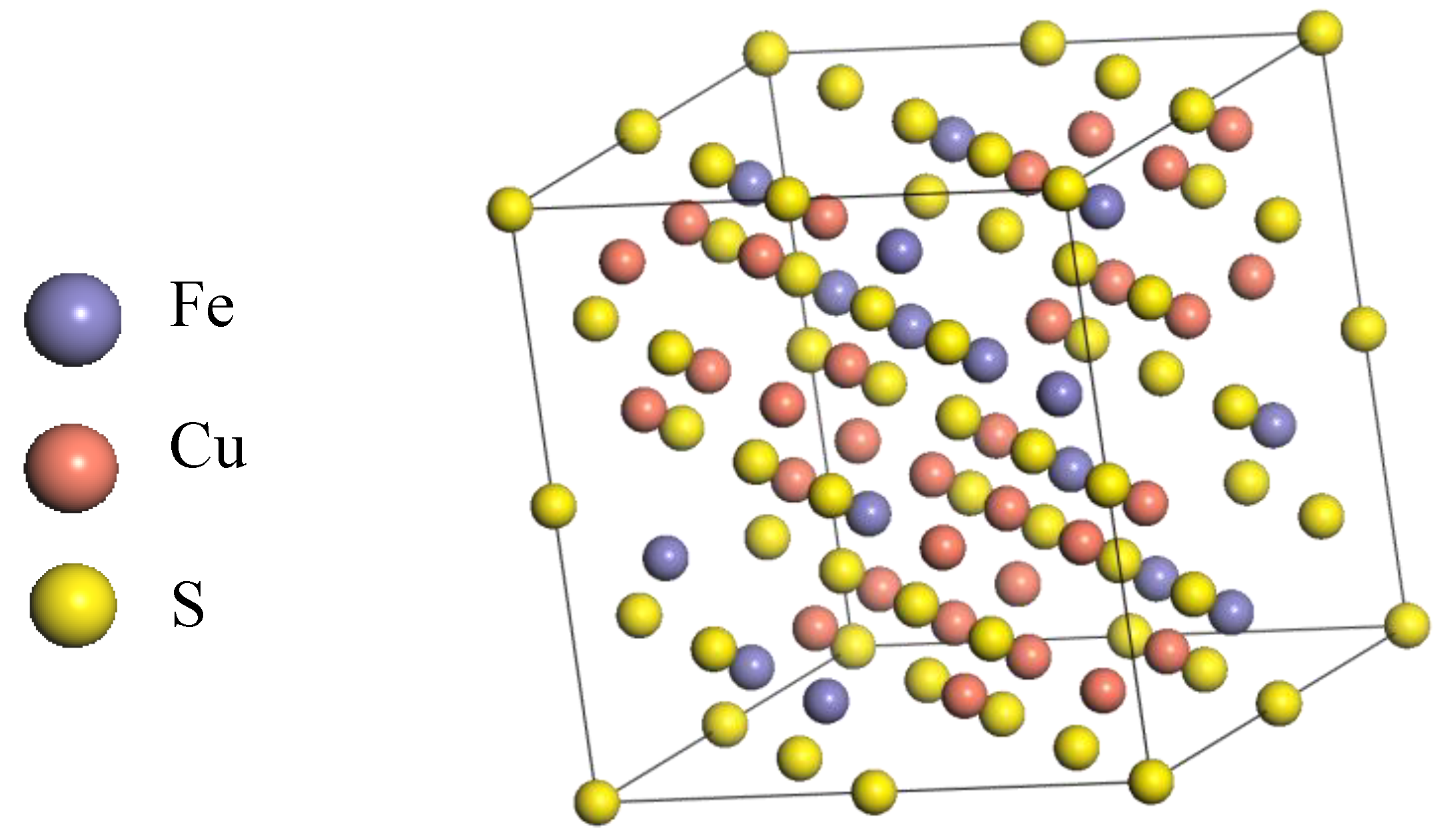
A cubic bornite unit cell with space group of F-43m was employed and its lattice parameters are shown in Figure 1 and Table 1, respectively. All DFT computations were performed using the CASTEP module in the Materials Studio 6.0 software package. The PBE density functional was chosen to account for the exchange-correlation potential [19,20]. To provide proper descriptions for the interactions between ions and their valence electrons, we adopted the ultrasoft pseudopotentials (USPP), where the valence shells were set to 3d64s2, 3d104s1 and 3s23p4 for Fe, Cu and S atoms, respectively. It is well known that the d and f electrons of transition metal atoms usually exhibit such strong correlations that an improper computation method often leads to irrational electron structures differing largely from experimental results. Accordingly, the Hubbard + U correction was usually employed [21,22,23]. In this work, the correction was employed in all energy, property and geometry optimization calculations. The U values for Cu and Fe were both 2.5, which were automatically set by CASTEP. Moreover, spin polarization was also taken into account with the initial spin obtained from the parameters of the aforementioned cubic unit cell model [24].
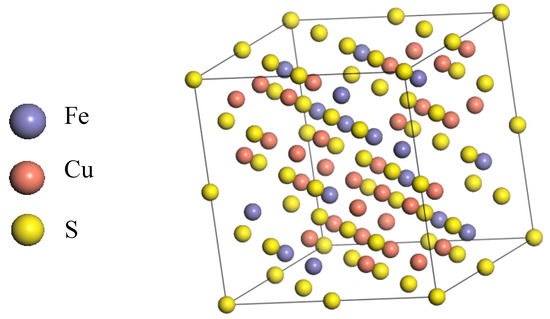
Figure 1.
The structure of F-43m bornite in DFT calculation.

Table 1.
Lattice constants of the bornite structure in DFT calculation (CASTEP module of Materials Studio 6.0 software package, PBE density function, Hubbard + U correction).
During geometry optimizations, the convergence thresholds were set to 1.0 × 10⁻⁵ eV/atom, 0.03 eV/Å and 0.001 Å for the total energies, the max force and the max displacement, respectively. The SCF convergence threshold was 1.0 × 10⁻⁶ eV/atom. A 3 × 3 × 3 k-point grid with a 400 eV kinetic energy cutoff was used. After structural relaxations, energy and property calculations were carried out using the same convergence thresholds, integration grids and cutoff.
To model the reconstruction of the (111)-S bornite surface, we adopted the lattice plane sliced from the optimized unit cell (the molar ratio of Cu: Fe: S within the plane was retained). Considering the symmetry properties and computational cost, finally we constructed a cell model which has half length of the a and b unit cell vectors and one unit length in the c axis (5 layers in total, the bottom 3 layers were fixed during modelling). To further eliminate the interactions between the top and bottom surface, a vacuum layer of 10 Å was added along the direction of the c axis. The convergence thresholds for modelling surface reconstruction were 2.0 × 10⁻⁵ eV/atom, 0.05 eV/Å and 0.002 Å for the total energies, the max force and the max displacement, respectively. The SCF convergence threshold was set to 2.0 × 10⁻⁶ eV/atom. A 3 × 3 × 1 k-point grid and a 400 eV cutoff were employed. After optimizations (i.e., reconstruction), energy and property calculations were performed using the same convergence thresholds, grids and cutoff.
2.2. Bioleaching Experiments
The moderately thermophilic microorganisms Acidithiobacillus caldus (A. caldus) (CCTC AB 206240) and Leptospirillum ferriphilum (L. ferriphilum) (CCTC AB 206239) were both initially acquired from the Key Lab of Bio-hydrometallurgy of the Ministry of Education, Central South University, Changsha, China. Bornite samples of high purity were obtained from Meizhou, Guangdong Province, China. The elements analysis indicates that the pure bornite samples contained 61.59% Cu, 10.04% Fe and 27.10% S (wt %), respectively. L. ferriphilum and A. caldus were sub-cultured into basal culture medium supplemented with 44.7 g/L ferrous sulfate (FeSO4·7H2O) and 10 g/L sulfur as energy source, respectively. Mixed culture consisting of L. ferriphilum and A. caldus was sub-cultured into basal culture medium supplemented with 44.7 g/L ferrous sulfate (FeSO4·7H2O) and 10 g/L sulfur as energy sources. When microorganisms grew to their exponential growth phase with cell density of higher than 1.0 × 10⁸ cells/mL, cells were harvested, centrifuged and washed. The obtained cells were inoculated into a 250-mL shake flask containing 100 mL of sterilized culture medium and 2 g of bornite samples. The shake flasks were placed into an orbital shaker at 170 rpm and 45 °C, pH was regulated around 1.70 with dilute sulfuric acid, and water lost through evaporation was supplemented with deionized water periodically.
2.3. Analytic Techniques
Metal ions concentrations were analyzed by inductively coupled plasma-atomic emission spectrometry (ICP-AES) (PS-6, Baird Co., Deford, MA, USA), meanwhile, pH and Oxidation-Reduction Potential (ORP) values were monitored with a pH meter (PHSJ-4A, Shanghai LEICI Co., Shanghai, China) and ORP meter (BPH-221, Dalian BELL Co., Dalian, China), respectively. Electrochemistry tests were conducted by conventional three-electrode system (Princeton Model 283 Potentiostat, EG&G of Princeton Applied Research, Princeton, NJ, USA). All the potential values mentioned were referred to the Ag/AgCl electrode (vs. Ag/AgCl) in this work. X-ray photoelectron spectroscopy (XPS) analysis was implemented on a model ESCALAB 250Xi instrument (Thermo Fisher Scientific Co., Waltham, MA, USA). The XPS spectra were recorded at a constant pass energy of 20 eV and 0.1 eV/step with Al Kα X-ray source. The Thermo Avantage 5.52 software (Thermo Fisher Scientific Co.) was used to fit the obtained XPS spectra, binding energies were referred to the C 1s level at 284.8 eV, the background of spectra was achieved by using the Shirley method, and the S 2p spectra were fitted by the Gaussian-Lorentzian line (SGL) function [25]. The S 2p spectra were fitted using a 2:1 peak area ratio and 1.2 eV splitting for S 2p3/2 and S 2p1/2. To investigate the surface transformation of bornite at different potentials, the bornite electrode was treated by different potentials for 3 h, and the treated bornite electrode was then analyzed by XPS. Bornite samples bioleached by different microorganisms for different numbers of days were analyzed by XPS to reveal the intermediate species on bornite surface during bioleaching.
3. Results and Discussions
3.1. DFT Calculations of the Bornite Surface
According to symmetry, we converted the unit cell into a primitive cell before our calculation. During our CASTEP calculation, we chose the following 3 parameters to check the convergence according to the energy cutoff and the results are shown in Table 2. The total energy of system changed slightly under 3 different settings of energy cut-off, and the value of dEtot/dElog (Ecut) also meets the requirements. It is noted that the number of SCF iterations under 400 eV decreased significantly. Based on the above, we can reach convergence fast and accurately by setting the energy cutoff at 400 eV.

Table 2.
Convergence test results of energy cut-off in DFT calculation (CASTEP module of Materials Studio 6.0 software package, PBE density function, Hubbard + U correction).
Table 3 shows the lattice parameters before and after optimization and the reference results. The relative error between the optimized lattice parameters and the reference results was 3.2% [24]. In combination with the results of convergence test, the optimization results were convincing. It can represent the actual structure of F-43m bornite. The consideration of spin and LDA + U corrections made our computations more reliable.

Table 3.
Results of cell parameters optimization in DFT calculation and reference (CASTEP module of Materials Studio 6.0 software package, PBE density function, Hubbard + U correction).
To analyze various kinds of properties of the F-43m bornite, we calculated the vacuum single point energy of the optimized structure. As shown in Table 4, we can get the analytical results of Cu, Fe, S atom orbital and total Mulliken population. From this table, we can see that the Fe atom transferred 0.46 electrons to the S atom (the electron cloud on Fe atom skewed to the S atom), part of the Cu atoms (Cu1-4) transferred 0.06 electrons to the S atom, while another part of the Cu atoms (Cu4-8) transferred 0.17 electrons to the S atom. These two different kinds of Cu atoms in different chemical environments suggested that the Cu atoms in F-43m bornite may exist in two different oxidation states.

Table 4.
Mulliken population of bornite in DFT calculation (CASTEP module of Materials Studio 6.0 software package, PBE density function, Hubbard + U correction).
Further analysis of the electronic structure of the whole cell of the F-43m bornite, especially the different oxidation states of the Cu atoms, as well as the bond population analysis is listed in Table 5. The value of the bond population reflects the degree of the bond covalence. The bond covalence increased with the increase of bond population value, and it’s completely a covalent bond when the value is equal to 1. When the value is equal to 0, it represents a completely ionic bond. The bonding between S and M (stand for metal) atoms in bornite was very complicated. The Cu1-4 not only bonded with the S atoms, but also had interactions with Fe atoms. (Cu1-4) transferred less electrons to the S atoms due to the covalency, thus causing Cu1-4 atoms existed in different chemical environments and with different oxidation states.

Table 5.
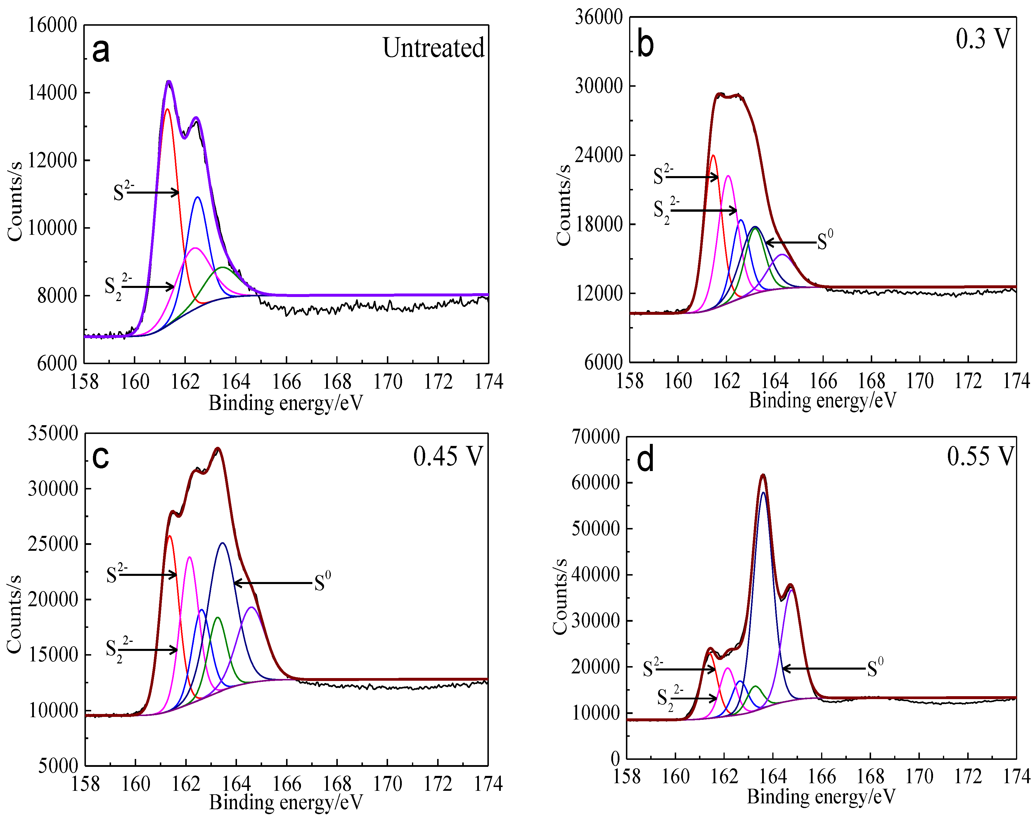
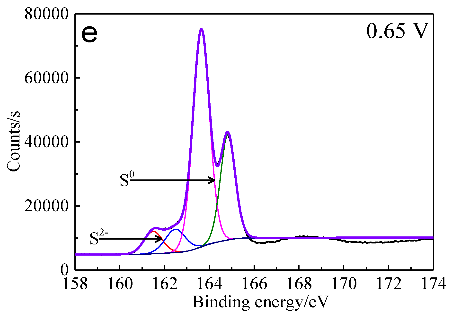
Binding energy and FWHM value for XPS spectra of S 2p3/2 peaks of bornite after treating by different potential of 0, 0.3, 0.45, 0.55, 0.65 V, respectively (Implemented on the model of ESCALAB 250Xi of Al Kα X-ray source with 20 eV constant pass energy and 0.1 eV/step; Fitted by Thermo Avantage 5.52, C 1s 284.8 eV as reference, Shirley method, Gaussian-Lorentzian function) (FWHM means full width at half maximum, B.E. means binding energy value).
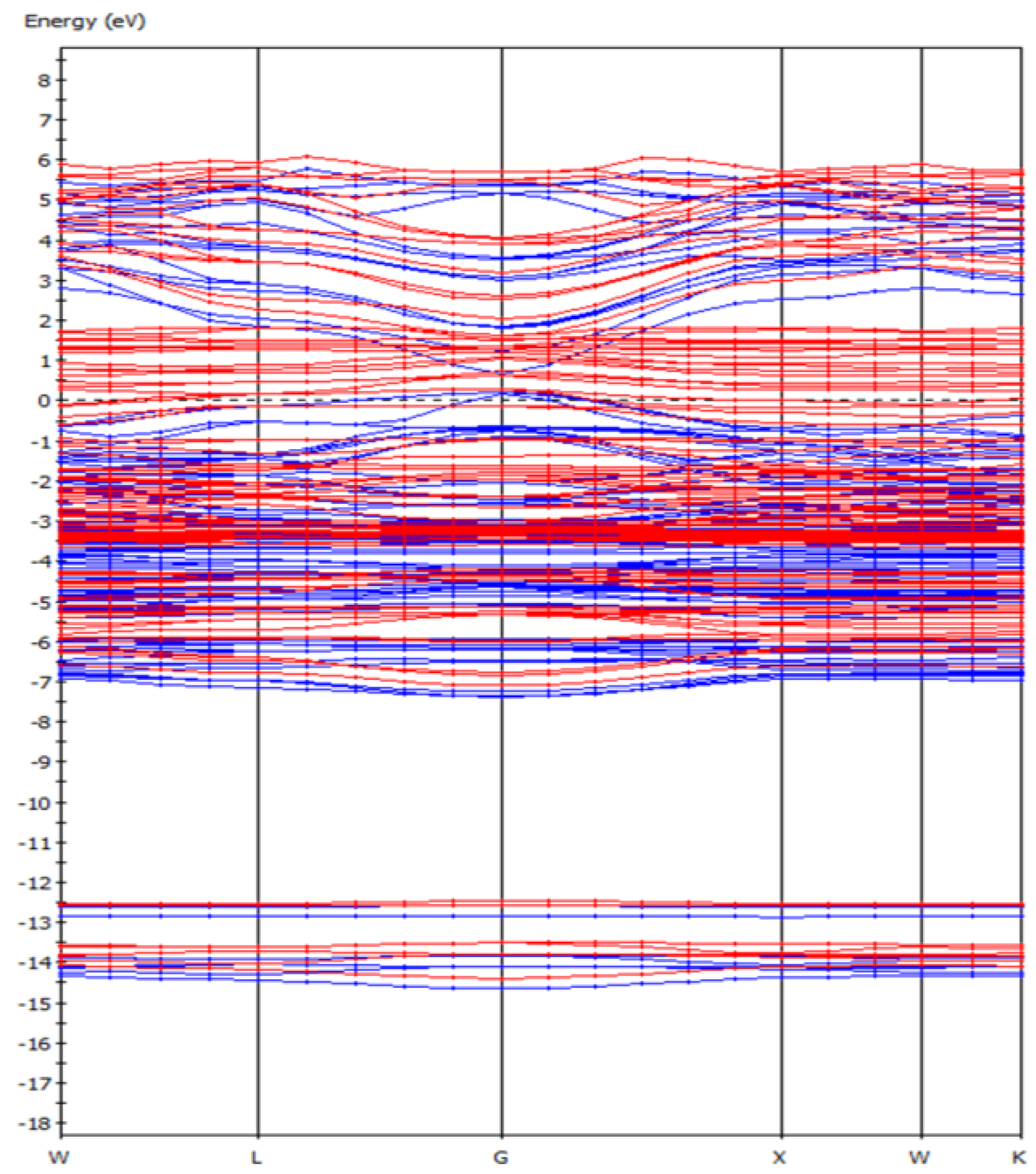
From the energy band diagram (Figure 2) of the F-43m bornite, we can find that the F-43m bornite is a conductor with metallic conductivity because its energy gap was almost 0 eV. This verified the Cu-Fe bonding effect in bond population analysis, whose behavior was similar to the electrons in metals.
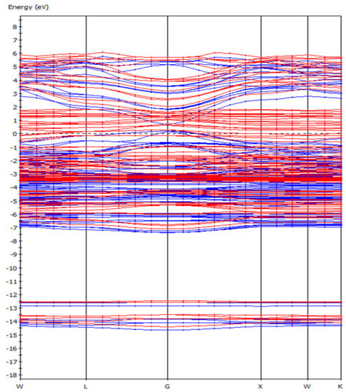
Figure 2.
The band structure of bornite (X-axis, High symmetry point; Y-axis, Energy/eV) in DFT calculation (CASTEP module of Materials Studio 6.0 software package, PBE density function, Hubbard + U correction).
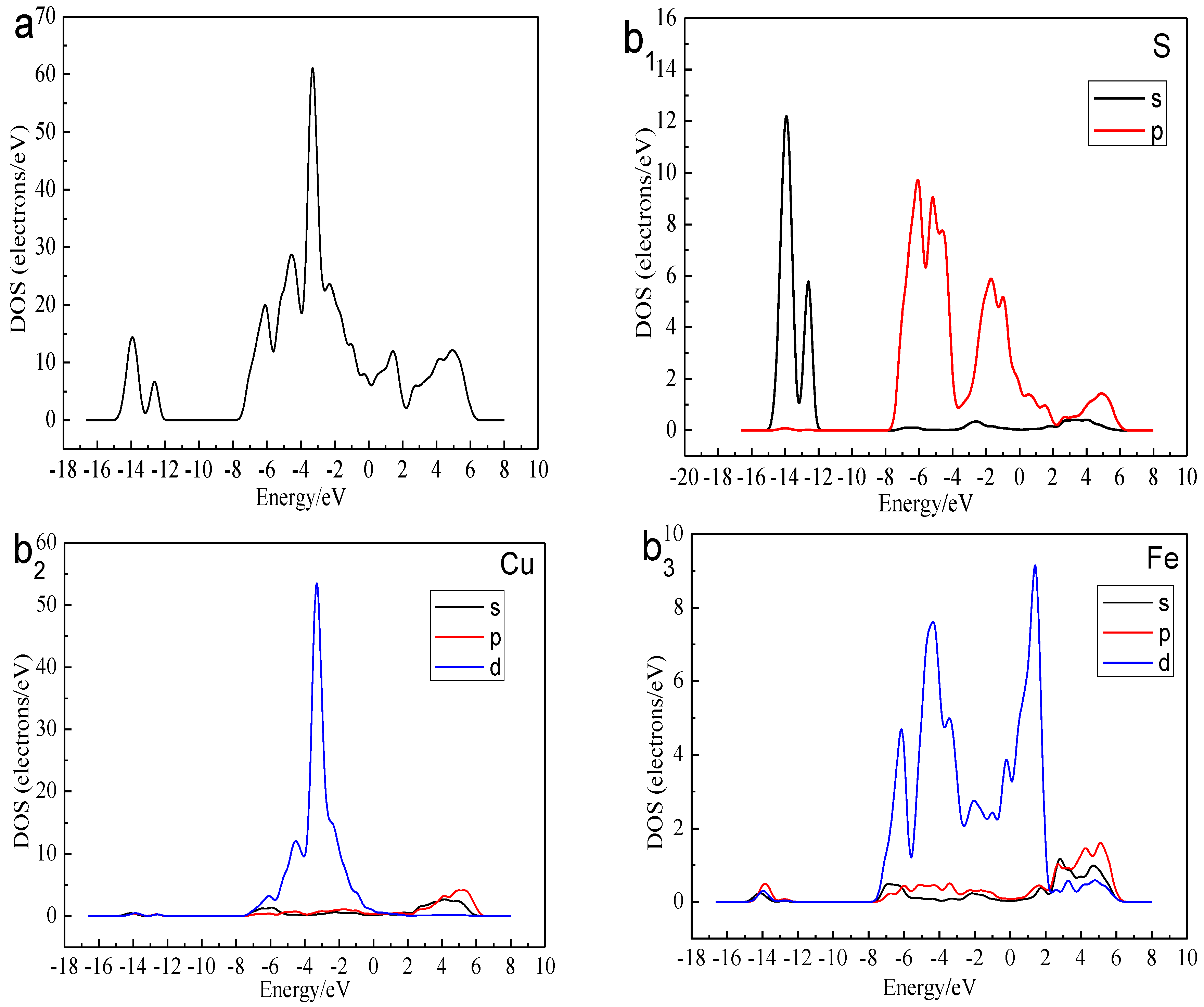
Figure 3 shows the total density of state (DOS) and the partial density of state (PDOS) of the Cu, Fe, and S atoms. We can find that the bottom of the valence bond band from −15.0 to −12.0 eV was mainly made up of the 3s orbital of S atoms. Lying between −8.0 and 0 eV were contributions of the combination of the 3d orbitals of Cu Atoms, 3d orbitals of Fe atom and 3p orbitals of S atoms. The conduction band between 0 and 2eV consisted of 3d orbitals of Fe atoms. The higher energy part was made up of the 4s orbital of Cu atom, 3p orbital of Cu atom, 4s orbital of Fe atom, 3p orbital of Fe atom and 3p orbital of S atom. The existence of the electrical conductivity was mainly due to the 3d orbitals of Fe atoms crossed over the Fermi level and interacted with the high-level orbitals of Cu atoms. Thus, the most active atoms in the F-43m bornite unit cell were the Fe atoms.
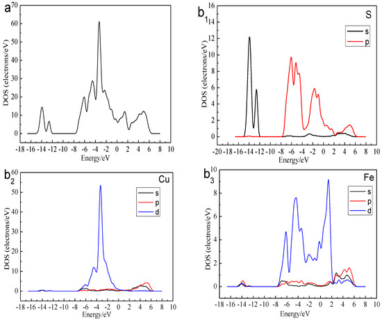
Figure 3.
DOS and PDOS of bornite in DFT calculation (CASTEP module of Materials Studio 6.0 software package, PBE density function, Hubbard + U correction): (a) Total; (b1) Cu; (b2) Fe; (b3) S.
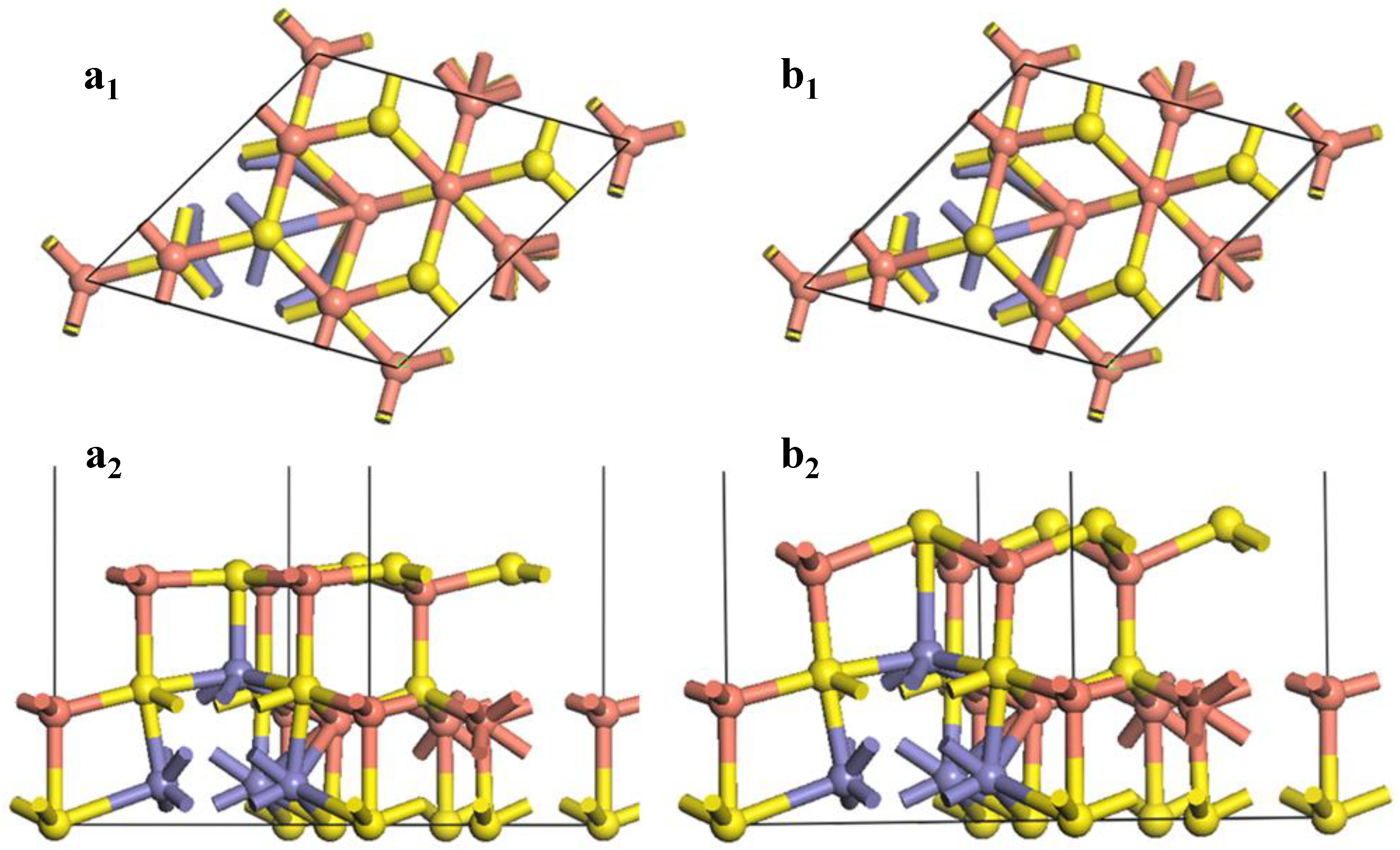
Figure 4 shows the changes of the (111)-S surface during the surface reconstruction.
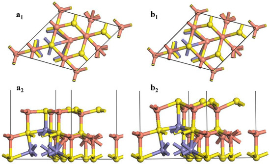
Figure 4.
Reconstruction of bornite (111)-S surface in DFT calculation (CASTEP module of Materials Studio 6.0 software package, PBE density function, Hubbard + U correction): (a1) Top and (a2) side views of optimized (111)-S surface; (b1) Top and (b2) side views of initial (111)-S surface.
At the F-43m bornite’s (111)-S surface, the first layer consisted of 4 S atoms, while the second layer was made up of 4 Cu atoms. After the surface relaxation, large variation occurred on the surface S-Cu bond. The bond length was reduced from 2.65696 Å to 2.33817 Å. The inter-layer angle of Cu-S-Cu changed from 109.471° to 119.785°. The original two layers were almost rearranged to be a new layer. The bond length of the S atom in the third layer and the Cu atom in the surface floor extended from 2.29674 Å to 2.59200 Å after optimization. Such a Cu-S bond was easier to break caused by surface reactions. The bond length of the Fe atom in the third layer and the S atom in the surface was reduced from 2.80266 Å to 2.33817 Å after optimization. Such a change of the surface morphology resulted in some variations of the reactivity of atoms. The inner core Cu atoms were exposed, making them easier to react with chemicals. The shortening of the Fe-S bond enhanced the Fe-S bond covalence, reducing the reaction activity of the Fe atoms.
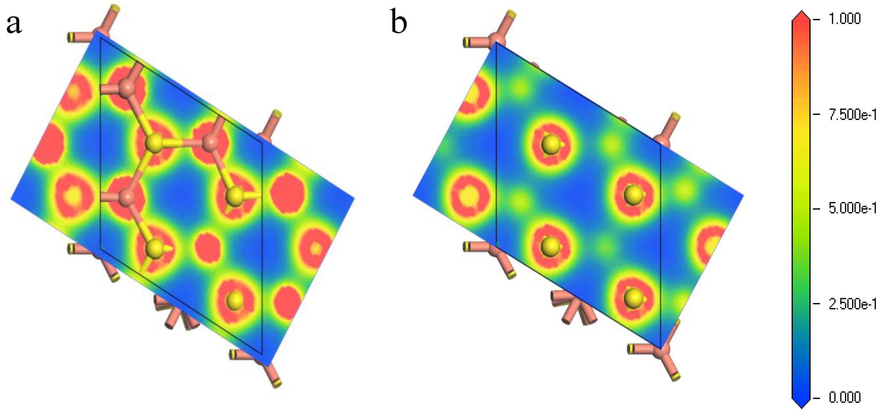
Figure 5 exhibits the electron density population of the first shell atoms of the (111)-S surface before and after optimization. The bonding overlap of Cu-S revealed that the inner Cu atoms were exposed to the surface after relaxation, leading to the increase of electron density on the surface. This facilitated the reaction between reactant and the bornite (111)-S surface. In other words, the (111)-S surface lost electrons and the reactant obtained electrons, making the bornite (111)-S surface oxidized.
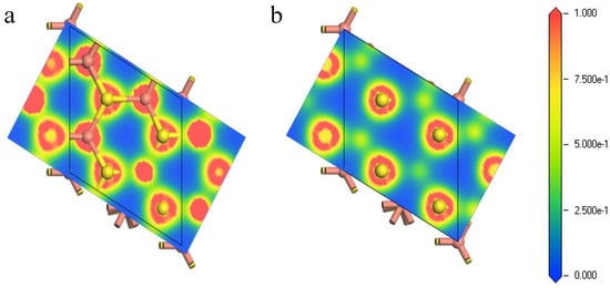
Figure 5.
Electron density of bornite (111)-S surface before and after reconstruction in DFT calculation (CASTEP module of Materials Studio 6.0 software package, PBE density function, Hubbard + U correction): (a) The first layer of optimized (111)-S surface; (b) The first layer of initial (111)-S surface.
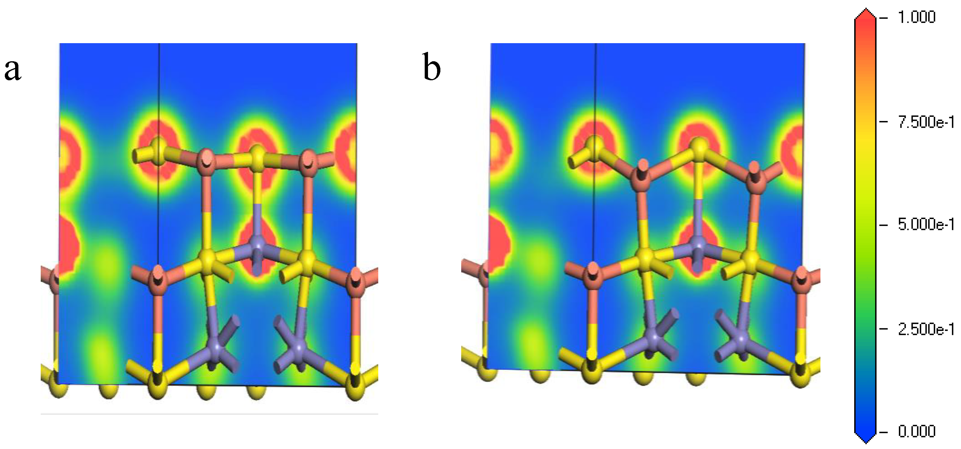
Figure 6 shows the electron density of the Fe-S bond from the core Fe atoms and the surface S atoms at (111)-S surface. It can be seen from Figure 6 that the bonding overlaps of the surface S atoms and inner Fe atoms became larger after relaxation, implying that tighter bonding occurred between the inner Fe atoms and the surface S atoms. Thus, the corresponding Fe-S bonds were relatively hard to break, causing that during the initial stages of chemical reactions on the (111)-S surface, and the inner irons can hardly participate.
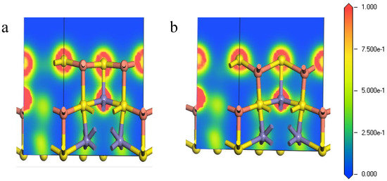
Figure 6.
Electron density of Fe-S bond of bornite (111)-S surface before and after reconstruction in DFT calculation (CASTEP module of Materials Studio 6.0 software package, PBE density function, Hubbard + U correction): (a) The optimized Fe-S bond; (b) The initial Fe-S bond.
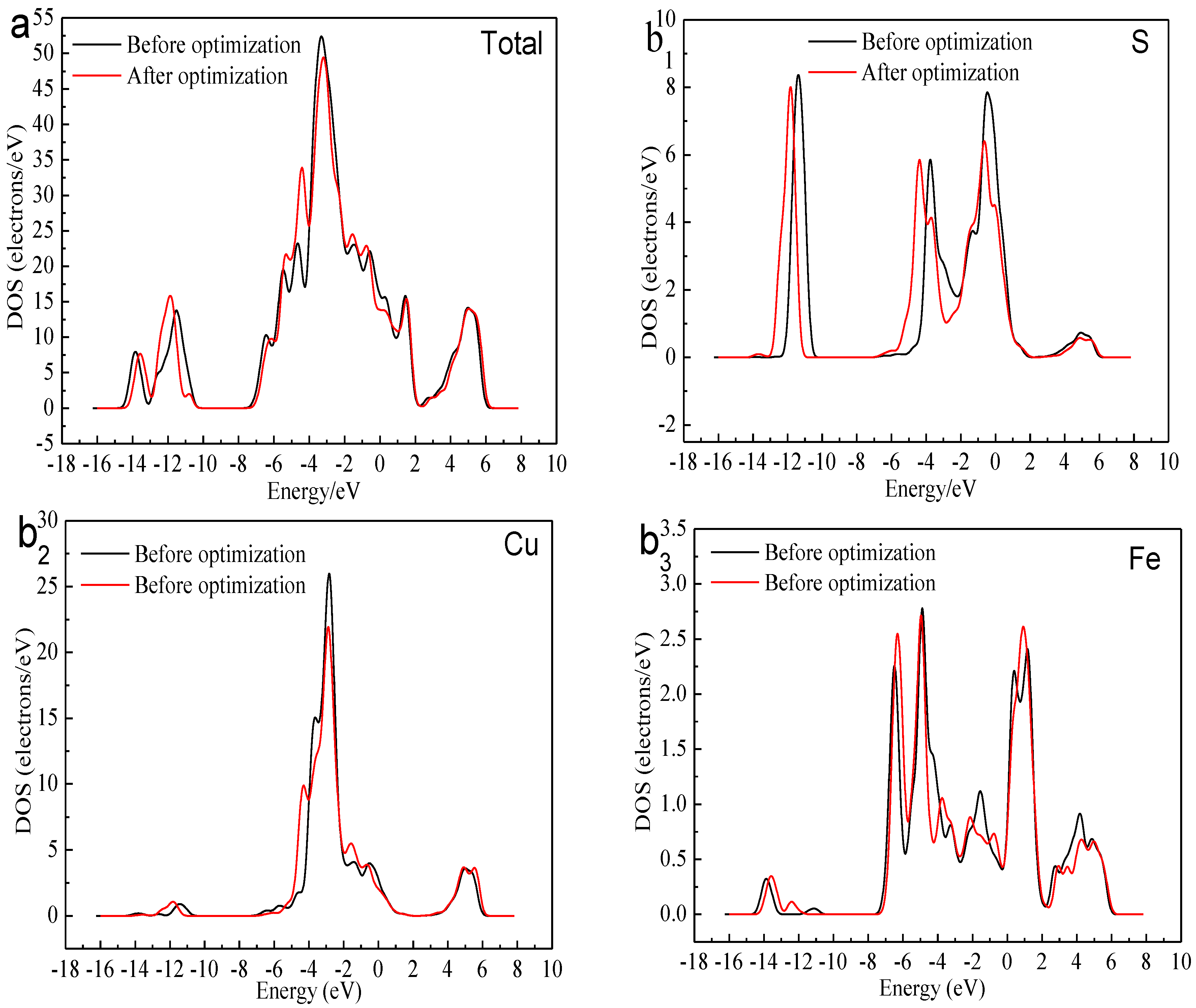
Analysis of the local density of states (LDOS) of the surface Cu and S atoms, and inner iron atoms is shown in Figure 7. By comparing the total values of LDOS before and after relaxation, we can see that the DOS of (111)-S plane decreased within the −1 to 0 eV energy range. This suggested an oxidation process occurred during relaxation. If we look more in detail into the DOS of various surface atoms (Cu, Fe and S), within the range of −1 to 0 eV: the DOS of iron atoms increased, copper atoms decreased slightly, and sulfur atoms diminished substantially. It clearly demonstrated that the Fe atoms obtained negative charges (i.e., electrons) from the S atoms and Cu atoms. In other words, the Cu and S atoms were oxidized while the Fe atoms were reduced. This corresponds well to the aforementioned analysis of electron densities.
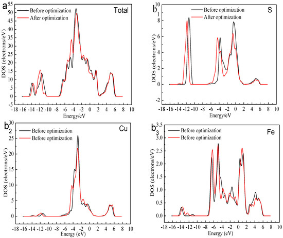
Figure 7.
Local DOS of bornite before and after optimization (CASTEP module of Materials Studio 6.0 software package, PBE density function, Hubbard + U correction): (a) Total; (b1) S; (b2) Cu; (b3) Fe in DFT calculation.
3.2. Surface Transformation of Bornite at Different Potentials
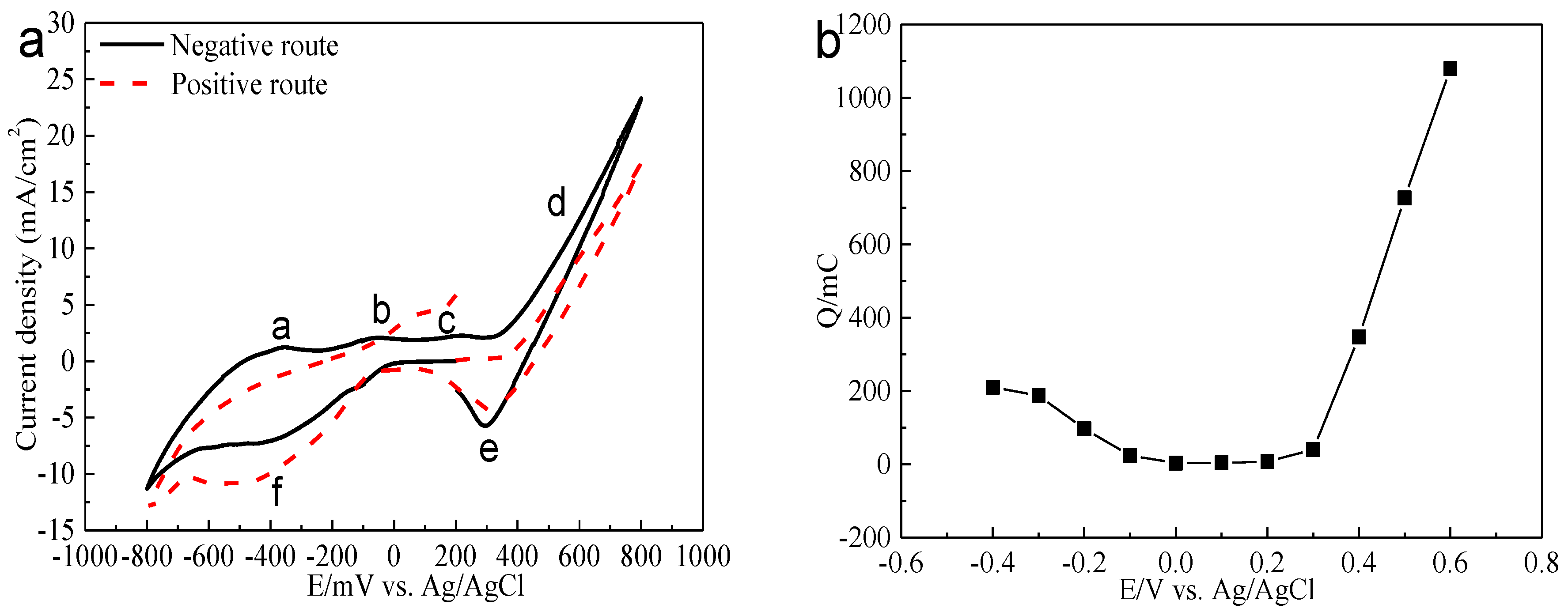
Electrochemistry analysis was carried out to interpret the electrochemical dissolution processes of bornite. The cyclic voltammograms of bornite in positive scan route and negative scan route are presented in Figure 8. Peaks a, b and c were considered as a continuous process composed of the formation and further oxidation of Cu2S [26,27,28,29]. Peak c can also represent the oxidation of hydrogen sulfide to elemental sulfur as shown in Equation (4) [27,30]. Peak d was the decomposition of bornite as shown in Equation (5) [26]. Peak e was considered to be the reduction of Fe3+ and bornite shown in Equations (6) and (7) [27,31,32]. Peak f should be the reduction of Cu2S to metal copper [31,33]:
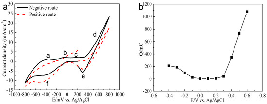
Figure 8.
Electrochemistry analysis of bornite in 9K bacterial culture medium (Conventional three-electrode system on a Princeton Model 283 Potentiostat, EG&G of Princeton Applied Research): (a) Cyclic voltammograms of bornite electrode (Scan rate 20 mV/s); (b) Relationship between the total charges (evaluated from the current-time curves with duration time of 240 s) and applied potentials.
The relationship between the total charge (Figure 8) and applied potential was calculated based on potentiostatic polarization testes. It was found that bornite has a high conductivity, especially at relatively high potentials. The oxidation rate was significantly higher than the reduction rate, indicating that bornite tended to be directly oxidized. This was different with chalcopyrite which was difficult to be oxidized and Ag+ is required to enhance the oxidation rate [34,35].
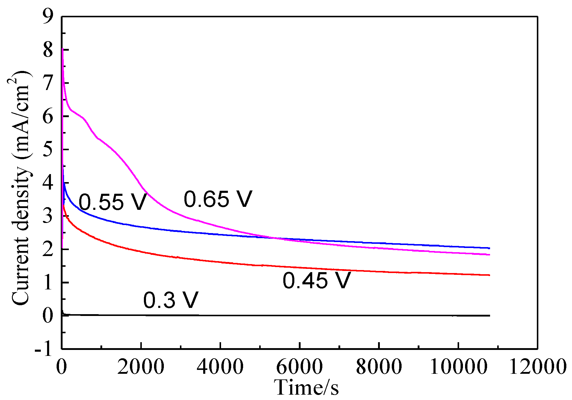
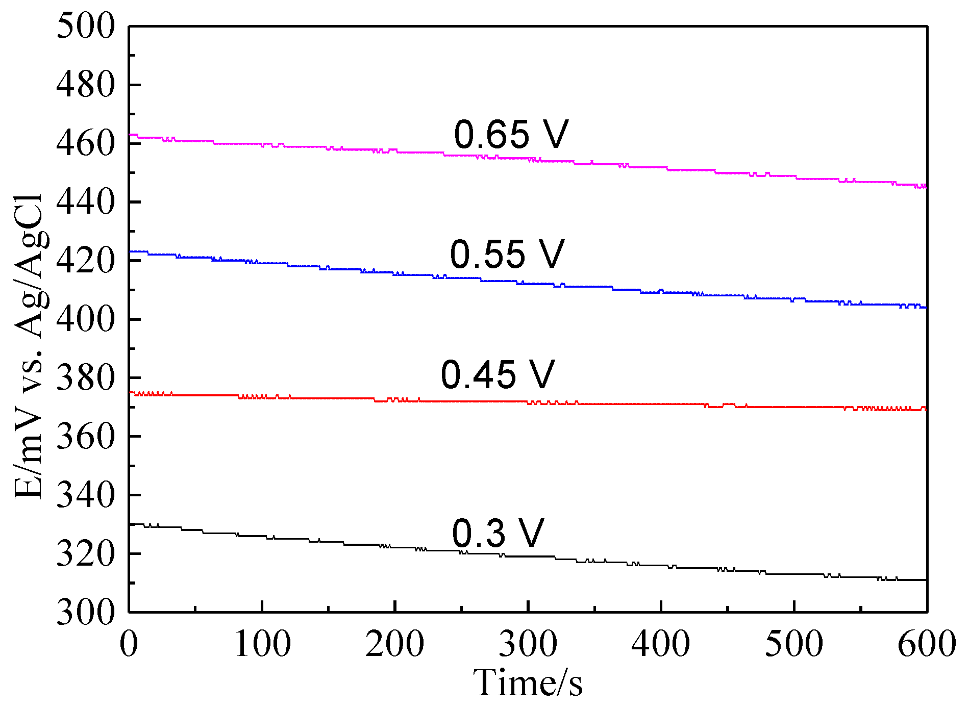
Bornite electrode was treated by different potentials for 3 h to further investigate the electrochemical dissolution process of bornite. Figure 9 shows the current-time curves of bornite electrode at different applied potentials for 3 h. The curves sharply declined and then kept steady, indicating that the oxidation reactions of bornite reached chemical equilibrium. Figure 10 presents the open circuit potentials (OCP) of bornite after treating by different potentials. The values of OCP significantly increased with the increase of applied potentials, indicating that higher potential was required to further oxidize the formed oxidation species on bornite surface. This may be mainly attributed to the accumulation of oxidation species on bornite species with the increase of potential.
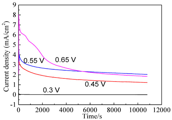
Figure 9.
Current-time curves of bornite electrode at different applied potentials for 3 h in 9K bacterial culture medium (Conventional three-electrode system on a Princeton Model 283 Potentiostat, EG&G of Princeton Applied Research).
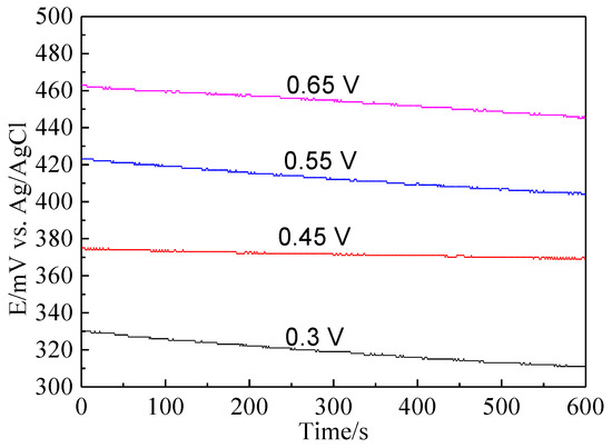
Figure 10.
The open circuit potential of bornite electrode after treating by different potentials for 3 h in 9K bacterial culture medium (Conventional three-electrode system on a Princeton Model 283 Potentiostat, EG&G of Princeton Applied Research).
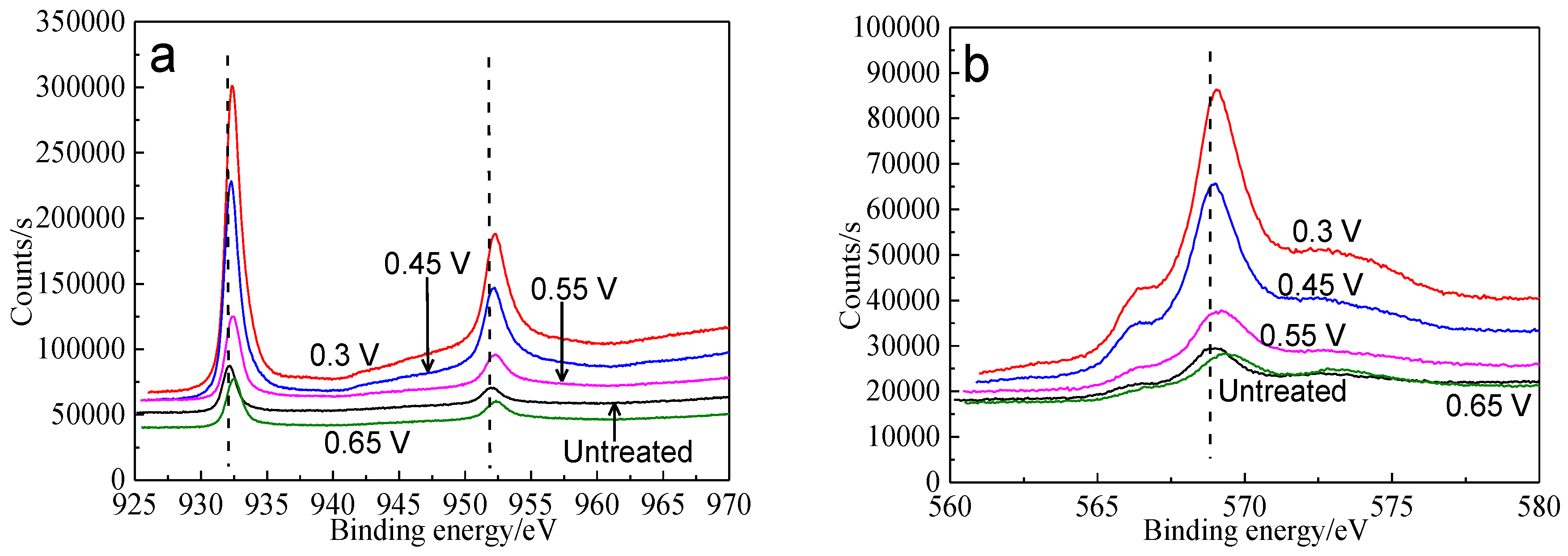
XPS was used to analyze the surface species of bornite after treating by different potentials, including copper-containing, iron-containing, sulfur-containing and oxygen-containing species. Figure 11 shows the XPS spectra of Cu peaks of bornite surface after treatment at different potentials, including Cu 2p peaks and Cu LMM peaks. It was reported that Cu 2p3/2 peak with a shake-up peak (at about 939–944 eV) was the major XPS characteristic of cupric species (Cu2+), and the Cu 2p3/2 peak without shake-up peak was the characteristics of cuprous species (Cu+) [36]. It can be found that all the Cu 2p3/2 peaks of bornite were centered at 932.2 eV without shake-up peak, which was in accordance with the reported value of bornite [36,37]. Therefore, the elemental Cu of bornite should mainly exist in the valence state of +1. The Cu 2p3/2 peaks of bornite surface after treating by different potentials were all centered at 932.2–932.4 eV, which were in accordance with the binding energy of CuS [38]. In addition, the values of binding energy increased with the increase of applied potentials, indicating that Cu element of bornite tended to be oxidized due to the increase of applied potentials. Cu LMM peaks of bornite after treating by different potentials were all centered at 568.5–569.0 eV, which agreed well with the reported value of CuS [39]. Hence, CuS should be the possible intermediate copper containing species on bornite surface during the oxidation process.
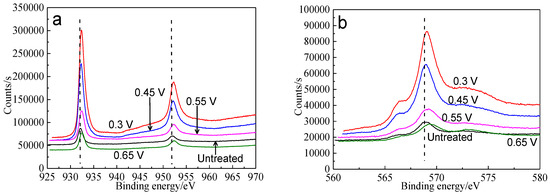
Figure 11.
XPS spectra of Cu peaks of bornite surface after treating by different potential of 0, 0.3, 0.45, 0.55, 0.65 V, respectively: (a) Cu 2p peak; (b) Cu LMM peak (Implemented on the model of ESCALAB 250Xi of Al Kα X-ray source with 20 eV constant pass energy and 0.1 eV/step; Fitted by Thermo Avantage 5.52, C 1s 284.8 eV as reference, Shirley method, Gaussian-Lorentzian function).
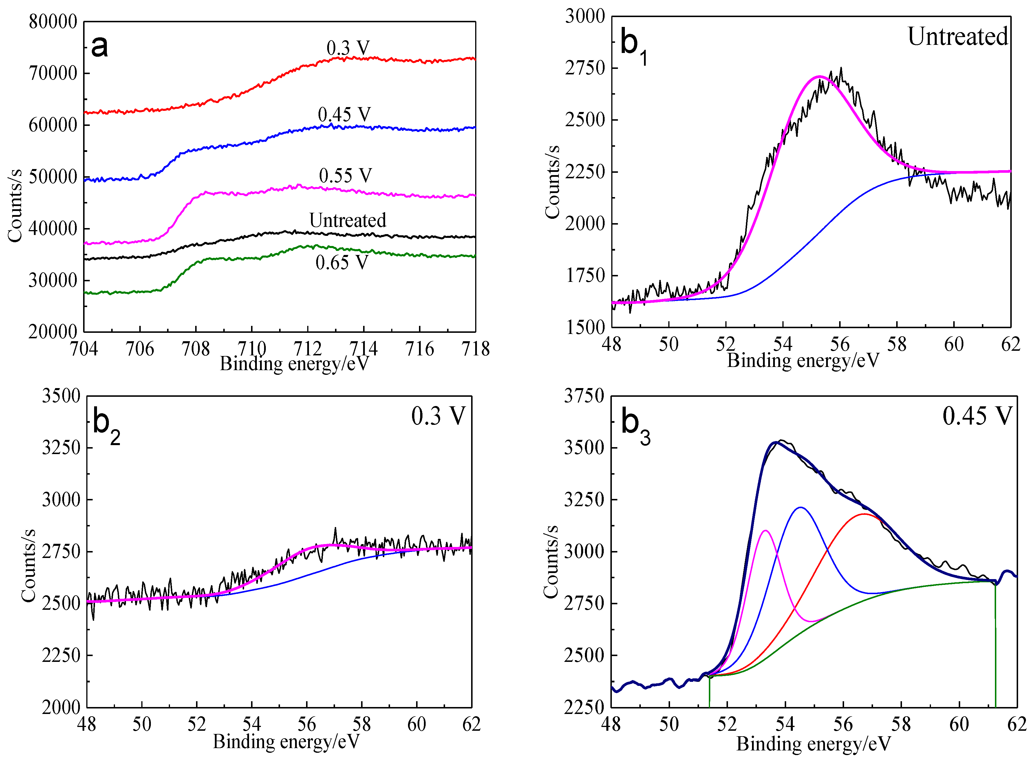
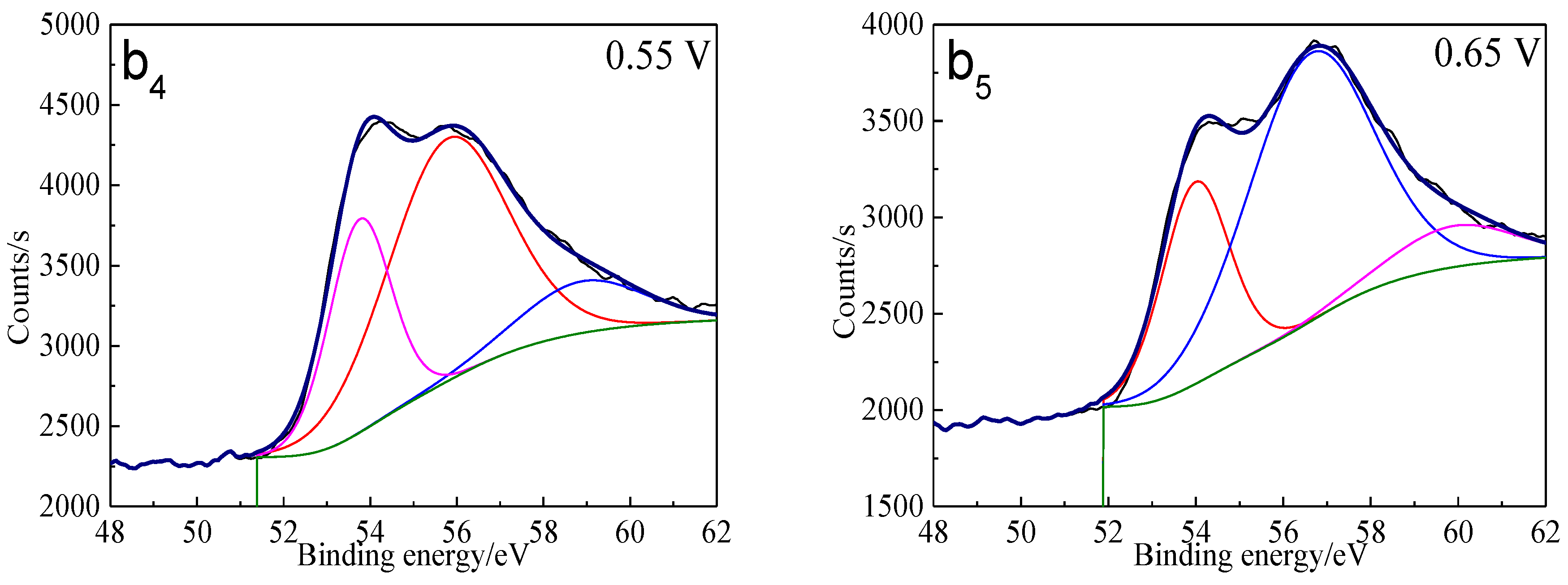
The Fe 3p spectra of bornite surface after treatment at different potentials are presented in Figure 12. Two main peaks can be detected at about 53.0–53.6 eV and 55.5–56.5 eV, respectively. The first peak centered at 53.0–53.6 eV can be assigned to Fe2+ bonded to sulfur in the species of FeS2 or FeS, while the second peak centered at 55.5–56.5 eV can be associated with Fe3+ in FeOOH [40]. Hence, Fe-S species and FeOOH should be the possible intermediate iron containing species during the oxidation process of bornite. Additionally, the percentage of FeOOH in iron containing species increased with the increase of applied potentials from analyzing the peak area.
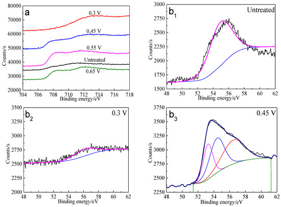
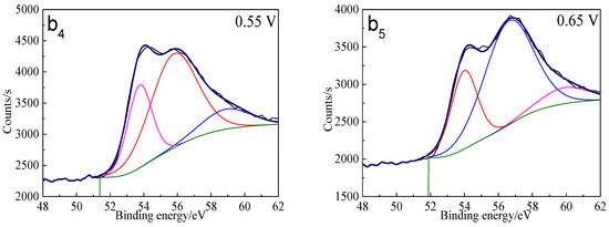
Figure 12.
XPS spectra of Fe peaks of bornite surface after treating by different potential of 0, 0.3, 0.45, 0.55, 0.65 V, respectively: (a) Fe 2p peak; (b1–b5): Fe 3p peak (Implemented on the model of ESCALAB 250Xi of Al Kα X-ray source with 20 eV constant pass energy and 0.1 eV/step; Fitted by Thermo Avantage 5.52, C 1s 284.8 eV as reference, Shirley method, Gaussian-Lorentzian function).
The S 2p peaks were fitted (Figure 13) and the S 2p3/2 values of binding energy and full width at half maximum (FWHM) are presented in Table 5. The types of sulfur containing species can be obtained by comparing with the references [41,42,43,44,45]. It can be found that monosulfide (S2−) and disulfide (S22−) were the main sulfur containing species on untreated bornite surface. S2−, S22− and elemental sulfur (S0) were the main sulfur containing species on bornite surface after treatment with different potentials, indicating that S2− and S22− can be oxidized to S0 when potential was higher than 0.3 V vs. Ag/AgCl.
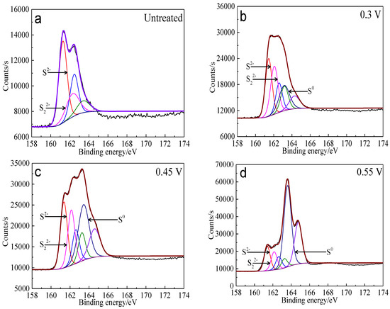
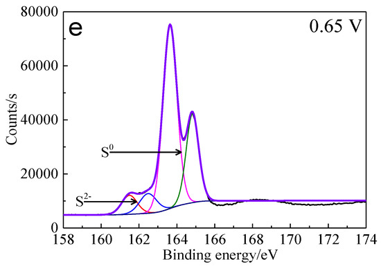
Figure 13.
XPS spectra of S 2p peaks of bornite surface after treating by different potential of 0, 0.3, 0.45, 0.55, 0.65 V, respectively: (a) Untreated; (b) 0.3 V; (c) 0.45 V; (d) 0.55 V; (e) 0.65V (Implemented on the model of ESCALAB 250Xi of Al Kα X-ray source with 20 eV constant pass energy and 0.1 eV/step; Fitted by Thermo Avantage 5.52, C 1s 284.8 eV as reference, Shirley method, Gaussian-Lorentzian function).
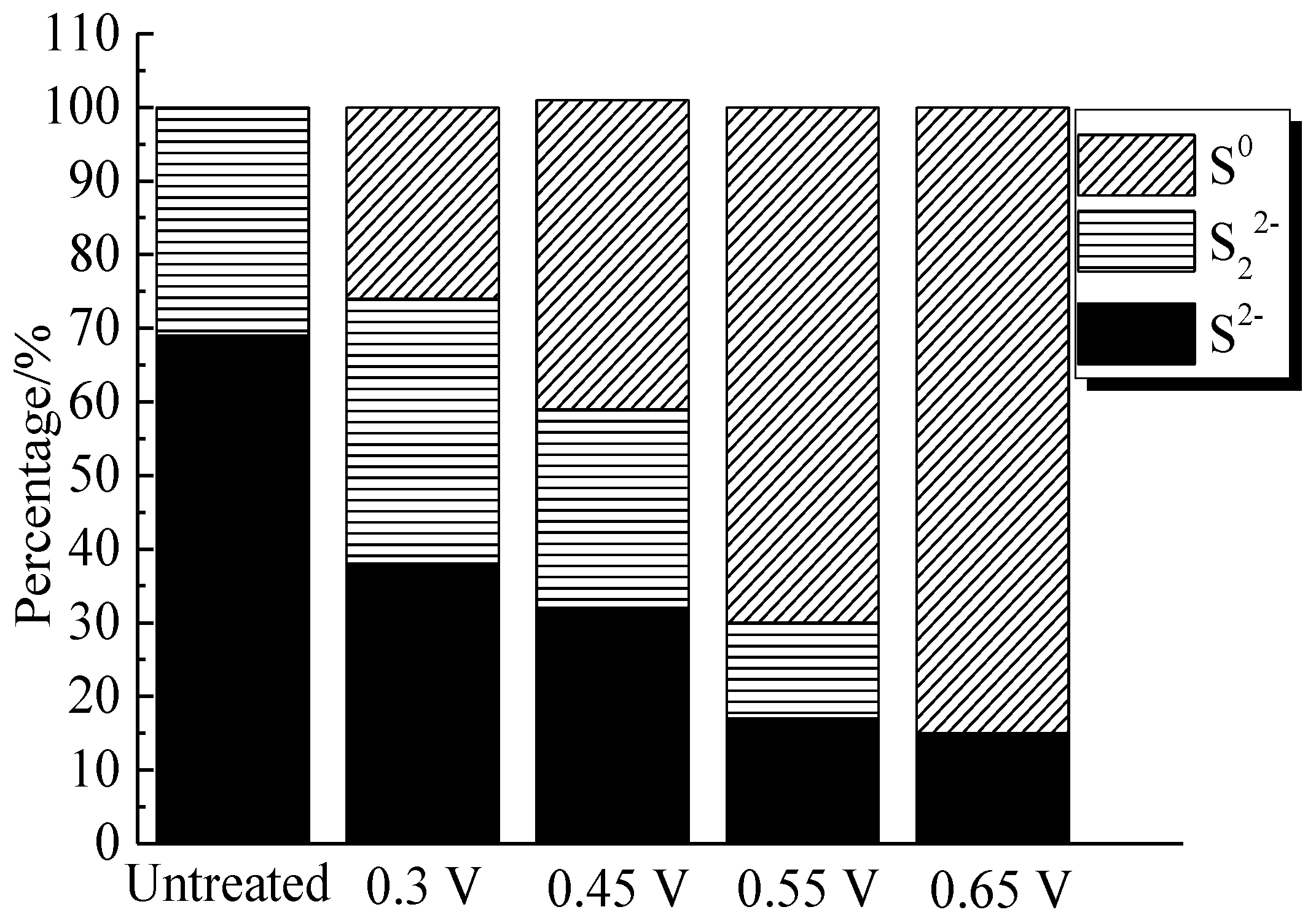
The percentages of sulfur containing species on bornite surface after treatment with different potentials were calculated from the peak areas, which are shown in Figure 14. It can be found that the total percentage of S2− and S22− decreased significantly from 100% to about 10%, and the proportion of S0 increased obviously from 0 to about 90% when the applied potentials increased from 0 to 0.65 V vs. Ag/AgCl. Hence, S0 was the main intermediate sulfur containing species on the bornite surface during the oxidation process and the production of S0 can be enhanced with the increase of applied potentials. In addition, no significant amount of insoluble sulfate (SO42−) formed on the bornite surface in 0.3–0.65 V vs. Ag/AgCl.
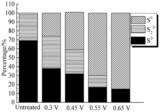
Figure 14.
Distribution of sulfur containing species on bornite surface after treating by different potential of 0, 0.3, 0.45, 0.55, 0.65 V, respectively (Implemented on the model of ESCALAB 250Xi of Al Kα X-ray source with 20 eV constant pass energy and 0.1 eV/step; Fitted by Thermo Avantage 5.52, C 1s 284.8 eV as reference, Shirley method, Gaussian-Lorentzian function).
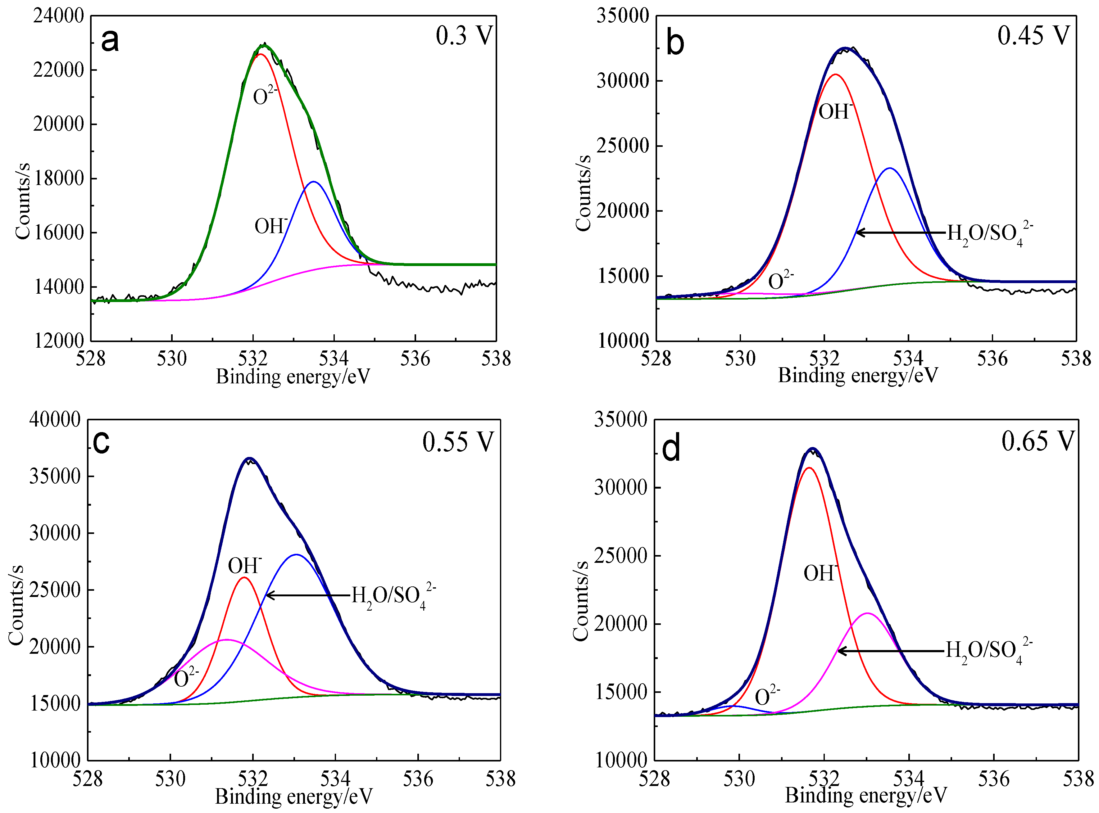
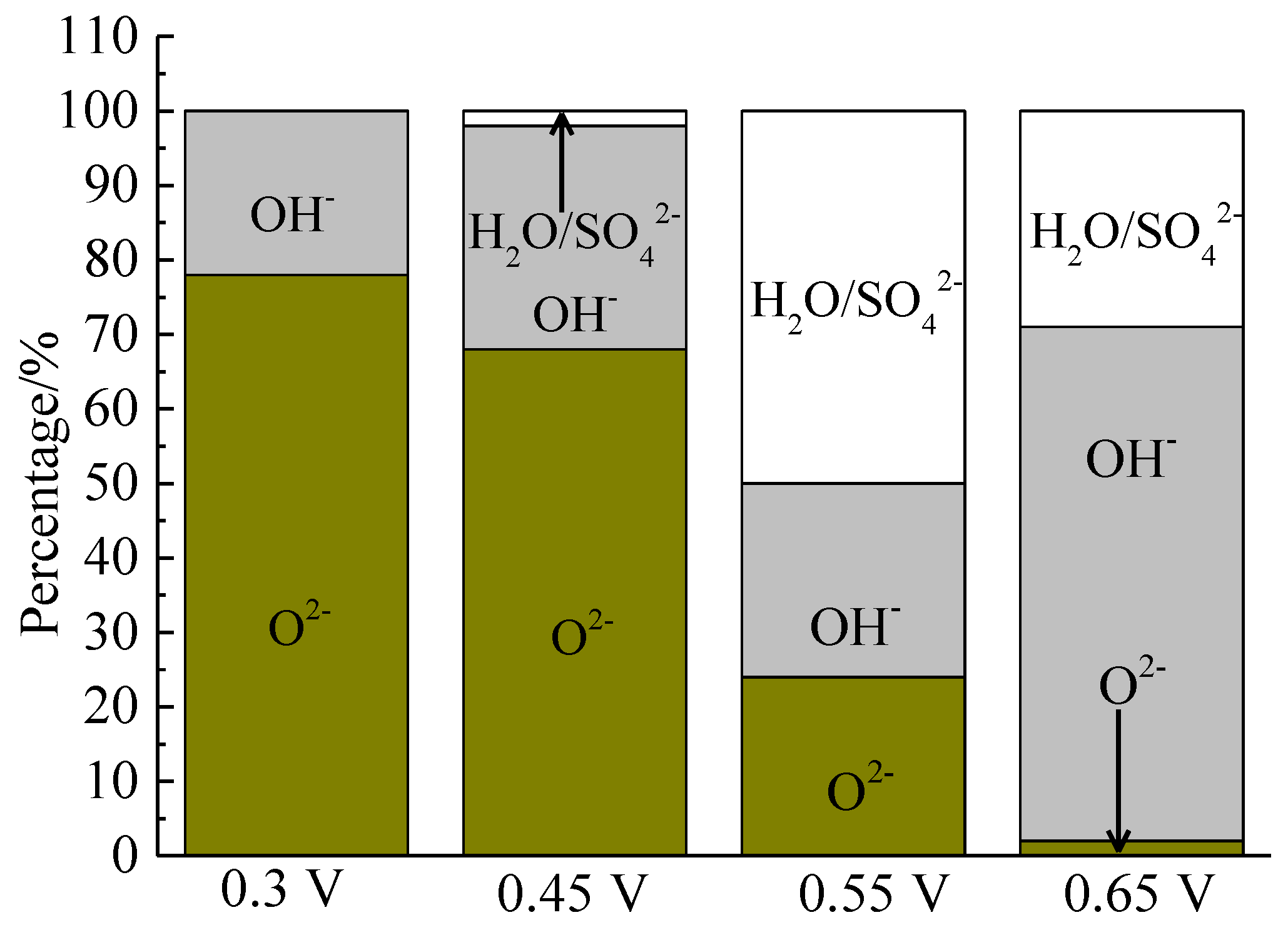
The XPS spectra of the O 1s peaks of the bornite surface after treatment with different potentials are shown in Figure 15. The binding energy of O 1s at 529.6 ± 0.1 eV, 531.5 ± 0.1 eV and 532.8 ± 0.1 eV can be mainly attributed to O2− in oxide phases, OH− in hydroxide species and oxygen in sulfate or/and water, respectively [36]. It can be found that O2− and OH− were the main oxygen containing species on bornite surface after treating at 0.3 V vs. Ag/AgCl, and sulfate or/and water formed at a higher potential. The percentage of oxygen containing species on bornite surface after treating by different potentials calculated from the peak area is shown in Figure 16. The percentages of O2− decreased significantly with the increase of applied potential, but the proportion of OH− increased with the increase of applied potential. This was consistent with the conclusion that the percentage of FeOOH in iron containing species increased with the increase of applied potentials from analyzing the Fe 3p peaks.
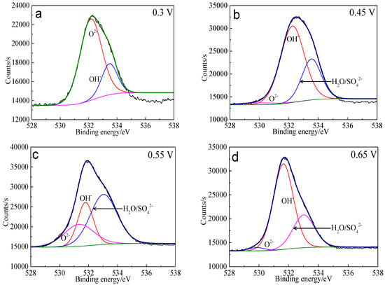
Figure 15.
XPS spectra of O 1s peaks of bornite surface after treating by different potential of 0, 0.3, 0.45, 0.55, 0.65 V, respectively: (a) 0.3 V; (b) 0.45 V; (c) 0.55 V; (d) 0.65 V (Implemented on the model of ESCALAB 250Xi of Al Kα X-ray source with 20 eV constant pass energy and 0.1 eV/step; Fitted by Thermo Avantage 5.52, C 1s 284.8 eV as reference, Shirley method, Gaussian-Lorentzian function).
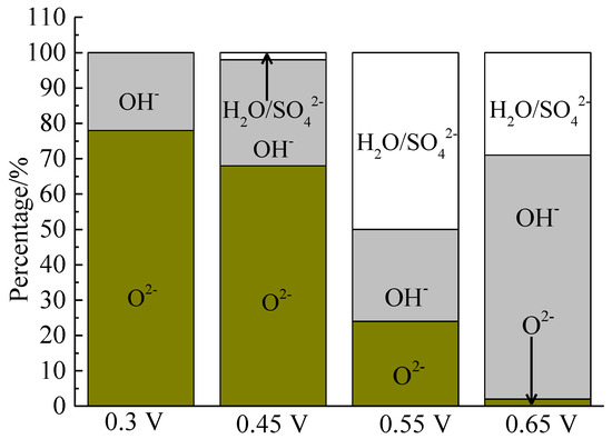
Figure 16.
Distribution of oxygen containing species on bornite surface after treating by different potential of 0, 0.3, 0.45, 0.55, 0.65 V, respectively (Implemented on the model of ESCALAB 250Xi of Al Kα X-ray source with 20 eV constant pass energy and 0.1 eV/step; Fitted by Thermo Avantage 5.52, C 1s 284.8 eV as reference, Shirley method, Gaussian-Lorentzian function).
3.3. Intermediate Species of Bornite Surface during Bioleaching
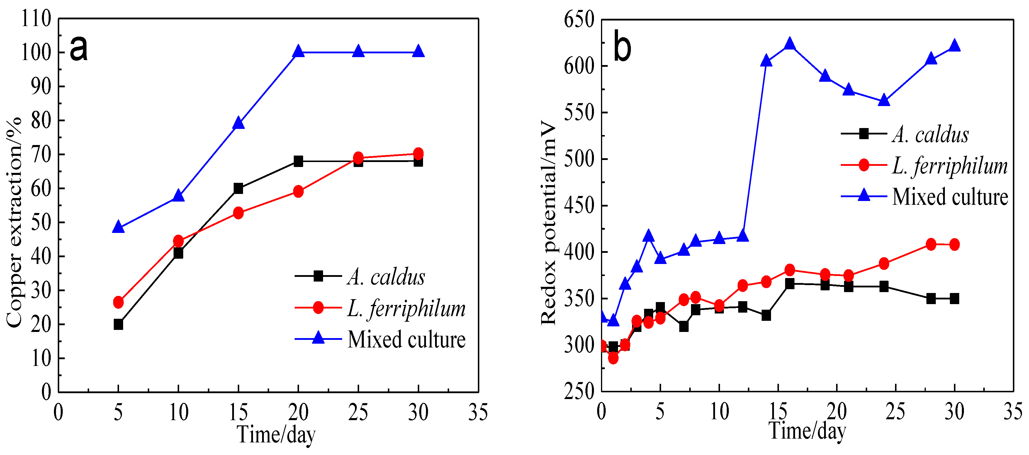
Bioleaching of bornite by A. caldus, L. ferriphilum and mixed culture was conducted. The variation of copper extraction and redox potential is presented in Figure 17. The redox potential during bornite bioleaching in the presence of mixed culture was higher than that in the presence of single strains of A. caldus and L. ferriphilum. Accordingly, the copper extraction of bornite bioleaching in the presence of mixed culture was also higher than that in the presence of single strains of A. caldus and L. ferriphilum. Redox potential during bornite bioleaching was in the range of 0.25–0.65 V vs. Ag/AgCl where bornite was mainly directly oxidized, and a high redox potential was beneficial for accelerating the oxidative dissolution of bornite. This was different with chalcopyrite bioleaching which can be accelerated at relatively low redox potential and passivated at high redox potential [46,47,48].
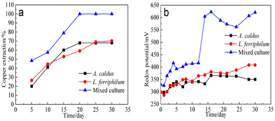
Figure 17.
Bioleaching of bornite by A. caldus, L. ferriphilum and mixed culture consisting of A. caldus and L. ferriphilum: (a) Copper extraction; (b) Redox potential.
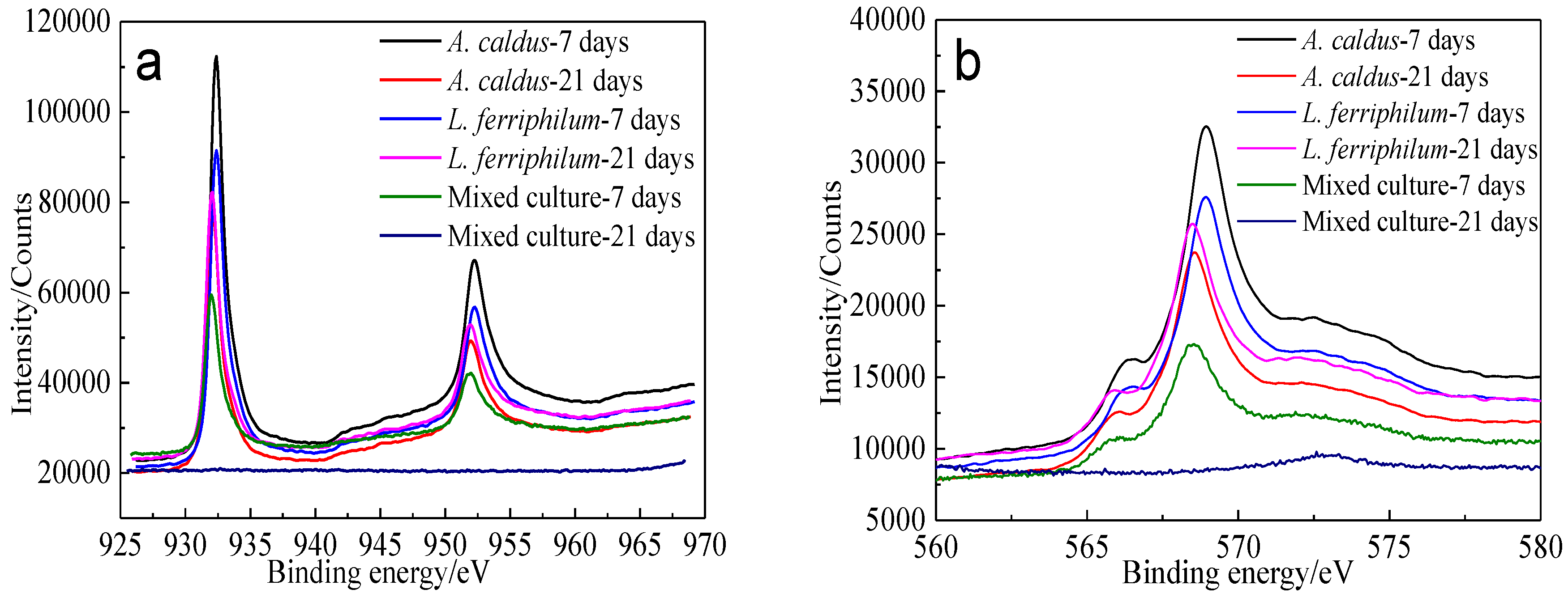
XPS spectra of Cu 2p peaks and Cu LMM peaks of bornite leached by different microorganisms for different numbers of days are shown in Figure 18.
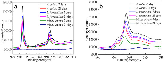
Figure 18.
XPS spectra of Cu peaks of bornite surface leached by A. caldus, L. ferriphilum and mixed culture consisting of A. caldus and L. ferriphilum for 7 and 21 days, respectively (Implemented on the model of ESCALAB 250Xi of Al Kα X-ray source with 20 eV constant pass energy and 0.1 eV/step; Fitted by Thermo Avantage 5.52, C 1s 284.8 eV as reference, Shirley method, Gaussian-Lorentzian function): (a) Cu 2p peak; (b) Cu LMM peak.
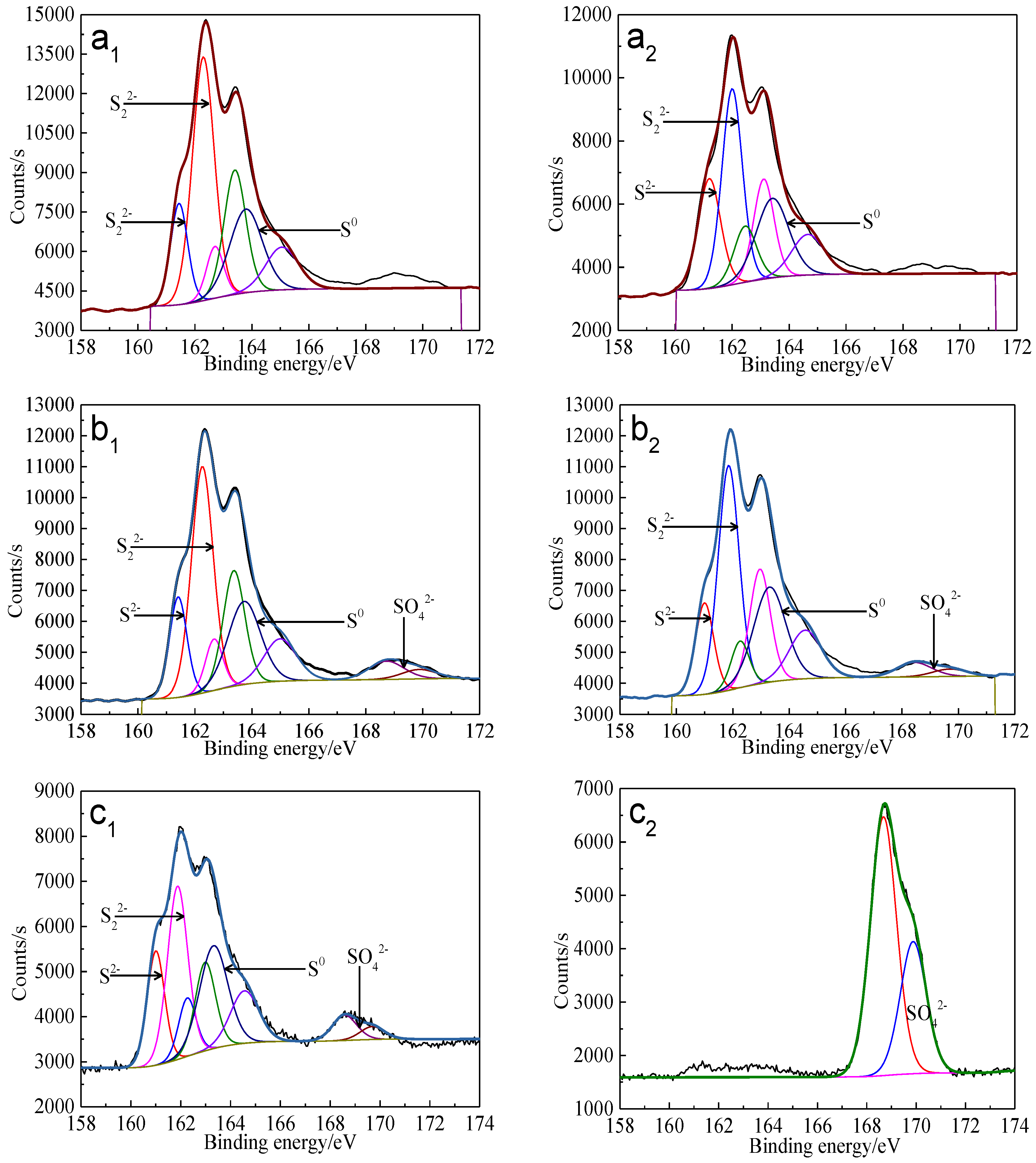
Cu 2p3/2 peaks of leached bornite samples were all centered at about 932.0–932.5 eV, and the Cu LMM peaks were all centered at about 568.0–568.7 eV, indicating that CuS should be the main intermediate copper containing species during bornite bioleaching [38,39]. The S 2p peaks were fitted (Figure 19) and the S 2p3/2 values of binding energy and full width at half maximum (FWHM) are presented in Table 6.
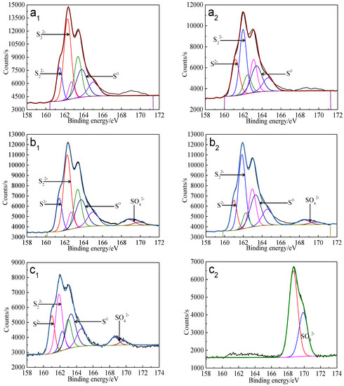
Figure 19.
XPS spectra of S 2p peaks of bornite surface leached by A. caldus, L. ferriphilum and mixed culture consisting of A. caldus and L. ferriphilum for 7 and 21 days, respectively (Implemented on the model of ESCALAB 250Xi of Al Kα X-ray source with 20 eV constant pass energy and 0.1 eV/step; Fitted by Thermo Avantage 5.52, C 1s 284.8 eV as reference, Shirley method, Gaussian-Lorentzian function): (a1)-A. caldus and 7 days; (a2)-A. caldus and 21 days; (b1)-L. ferriphilum and 7 days; (b2)-L. ferriphilum and 21 days; (c1)-mixed culture and 7 days; (c2)-mixed culture and 21 days.

Table 6.
Binding energy and FWHM value for XPS spectra of S 2p3/2 peaks of bornite leached by A. caldus, L. ferriphilum and mixed culture consisting of A. caldus and L. ferriphilum for 7 and 21 days, respectively (Implemented on the model of ESCALAB 250Xi of Al Kα X-ray source with 20 eV constant pass energy and 0.1 eV/step; Fitted by Thermo Avantage 5.52, C 1s 284.8 eV as reference, Shirley method, Gaussian-Lorentzian function) (FWHM means full width at half maximum, B.E. means binding energy).
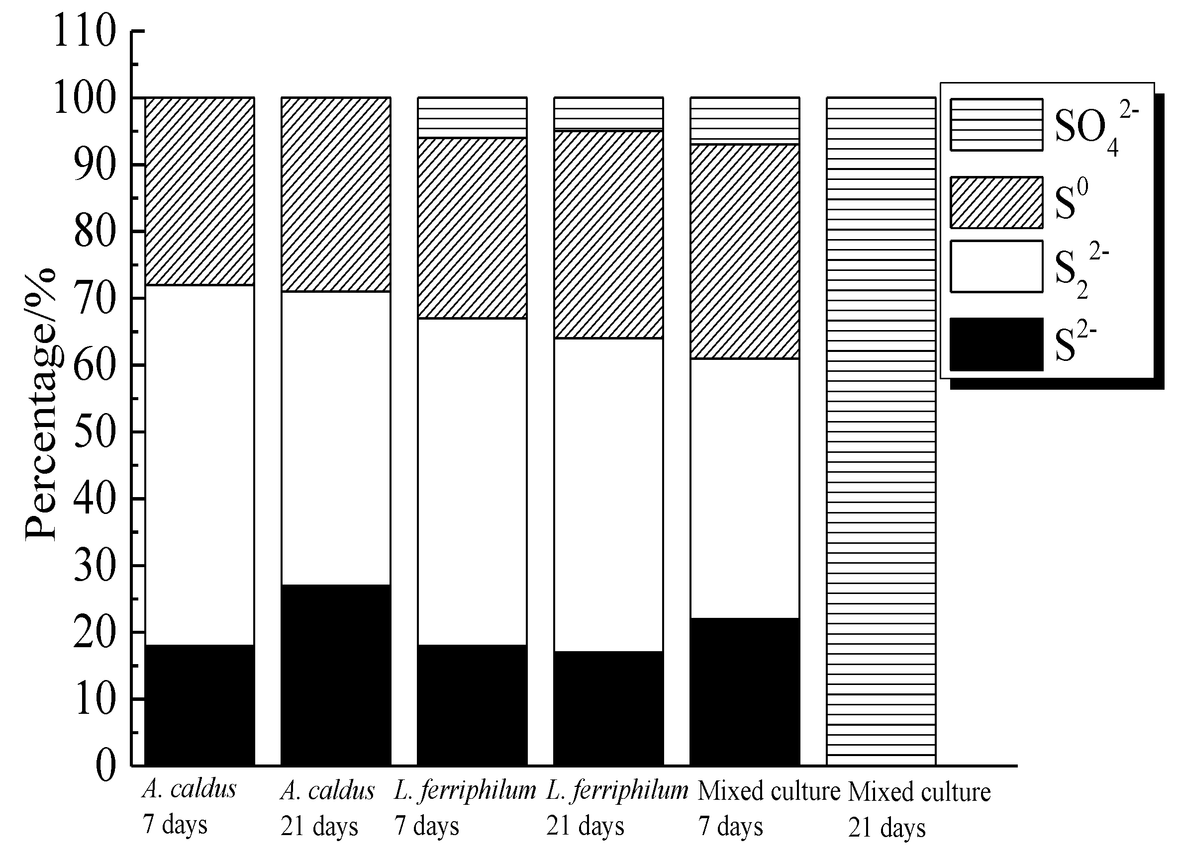
S2−, S22− and S0 were the main intermediate sulfur containing species on bornite surface during bioleaching by A. caldus. Except for S2−, S22− and S0, SO42− was detected as the main intermediate species on bornite surface during bioleaching by L. ferriphilum and by mixed culture. The distribution of sulfur-containing species on the bornite surface leached by different microorganisms for different days was calculated as shown in Figure 20. The proportions of S2−, S22− and S0 on bornite surface changed slightly during bioleaching by A. caldus, and the percentage of S0 kept around 28%. The percentages of sulfur containing species on the bornite surface during bioleaching by L. ferriphilum changed slightly and about 5% SO42− formed on the bornite surface. Particularly, the distributions of sulfur containing species on the bornite surface varied significantly during bioleaching by mixed culture and SO42− was the predominant sulfur containing species on the bornite surface at the end of bioleaching. Hence, the oxidative dissolution of bornite can be significantly accelerated at high redox potential, which was one important reason why mixed culture was more effective than single strains of A. caldus and L. ferriphilum.
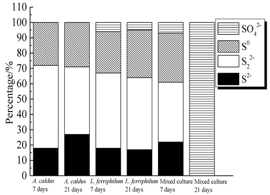
Figure 20.
Distribution of sulfur containing species on bornite surface leached by A. caldus, L. ferriphilum and mixed culture consisting of A. caldus and L. ferriphilum for 7 and 21 days, respectively (Implemented on the model of ESCALAB 250Xi of Al Kα X-ray source with 20 eV constant pass energy and 0.1 eV/step; Fitted by Thermo Avantage 5.52, C 1s 284.8 eV as reference, Shirley method, Gaussian-Lorentzian function).
3.4. The Proposed Model for Interpreting the Dissolution Process of Bornite during Bioleaching
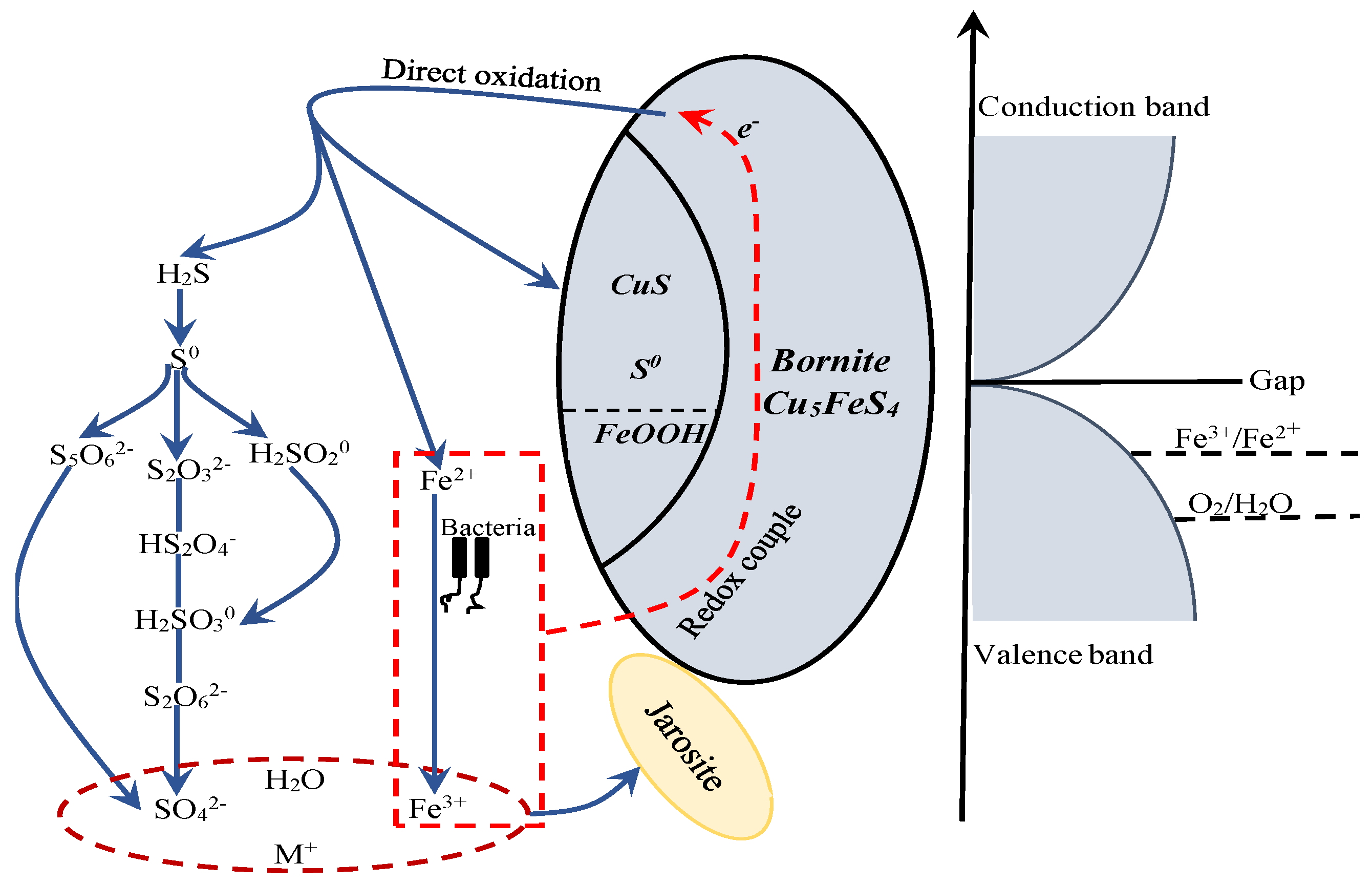
The proposed model for interpreting the dissolution process of bornite during bioleaching is provided in Figure 21. Bornite is a conductor with high metallic conductivity. The Eredox of redox couple of Fe3+/Fe2+ was located below the Fermi energy, so bornite can transfer electrons to the Fe3+/Fe2+ couple and be oxidized. The Eredox of redox couple of O2/H2O was always situated below the Fermi energy and in the range of valence band, but the content of dissolved O2 was extremely low at normal pressure, that was why redox potential in bioleaching system was mainly determined by Fe3+/Fe2+ couple [46,49]. Bornite tended to be directly oxidized to CuS, FeOOH and S0 on the surface, H2S and Fe2+ in the solution at potential of higher than 0.3 V vs. Ag/AgCl. The production of S0 and FeOOH on bornite surface can be significantly accelerated with the increase of redox potential but the formed elemental sulfur did not further oxidize to insoluble sulfate. H2S can be further oxidized to SO42− through series of intermediate species, and Fe2+ can be oxidized to Fe3+ by microorganisms. The redox couple of Fe3+/Fe2+ acted as the main oxidant in directly oxidizing bornite, and insoluble sulfate of jarosite can be produced through the chemical reaction of Fe3+, SO42−, H2O and M+ in solution as shown in Equation (9), where M is a monovalent cation, such as H3O+, Na+, K+ and NH4+:
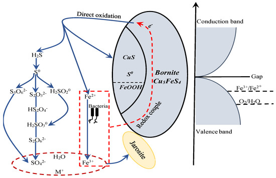
Figure 21.
The proposed model for interpreting the dissolution process of bornite in bioleaching by moderately thermophilic microorganisms.
4. Conclusions
Bornite with formula of (Cu+)5Fe3+(S2−) is a conductor with metallic conductivity whose behavior was similar to that of metals. The existence of the electrical conductivity was mainly due to the 3d orbitals of Fe atoms crossed over the Fermi level and interacting with the high-level orbitals of Cu atoms, thus making Fe atoms the most active species in the bornite unit cell. After reconstruction of (001)-S surface, the inner core Cu atoms were exposed, making them easily react with chemicals. The shortening of the Fe-S bond enhanced the Fe-S bond covalence, reducing the reaction activity of the Fe atoms. The inner Cu atoms were exposed to the surface after relaxation, which increased the electron density on the surface and facilitated the reaction between reactant and the bornite (111)-S surface. Tighter bonding occurred between the inner Fe atoms and the surface S atoms. Thus, the corresponding Fe-S bonds were relatively hard to break. Therefore, during the initial stages of chemical reactions on the (111)-S surface, the inner irons can hardly participate. The Cu and S atoms were oxidized while the Fe atoms were reduced in surface reconstruction.
Bornite tended to be directly oxidized to CuS, FeOOH and S0 on the surface, H2S and Fe2+ in the solution at potential of higher than 0.3 V vs. Ag/AgCl. The redox couple of Fe3+/Fe2+ acted as the main oxidant in directly oxidizing bornite. H2S can be further oxidized to SO42− through series of intermediate species. The formed elemental sulfur on bornite surface did not further oxidize to insoluble sulfate which can be produced through the chemical reaction of Fe3+, SO42−, H2O and M+ in solution. High redox potential was beneficial for the oxidative dissolution of bornite, which was one important reason why mixed culture was more effective than single strains of A. caldus and L. ferriphilum. This work can help to improve the bioleaching kinetics of bornite and chalcopyrite as well as help to elucidate the biomineralization of Cu-sulfides and the geo-biological-chemical circulation on the Earth.
Acknowledgments
This work was supported by the National Natural Science Foundation of China (project No. 51704331, 51774332 and 51374248), Young Elite Scientists Sponsorship Program by CAST (2017QNRC001) and Innovation-Driven Project of Central South University (2018CX019).
Author Contributions
Hongbo Zhao conceived and designed the experiments; Xiaotao Huang, Minghao Hu, Yisheng Zhang and Hongbo Zhao performed the experiments; Hongbo Zhao, Minghao Hu and Chenyang Zhang analyzed the data; Jun Wang, Wenqing Qin and Guanzhou Qiu contributed reagents/materials/analysis tools; Hongbo Zhao wrote the paper.
Conflicts of Interest
The authors declare no conflict of interest. The Funding sponsors had no role in the design of the study; in the collection, analyses, or interpretation of data; in the writing of the manuscript, and in the decision to publish the results.
References
- Brierley, C.L. Biohydrometallurgical prospects. Hydrometallurgy 2010, 104, 324–328. [Google Scholar] [CrossRef]
- Liu, H.; Xia, J.; Nie, Z.; Ma, C.; Zheng, L.; Hong, C.; Zhao, Y.; Wen, W. Bioleaching of chalcopyrite by acidianus manzaensis under different constant pH. Miner. Eng. 2016, 98, 80–89. [Google Scholar] [CrossRef]
- Liu, H.C.; Xia, J.L.; Nie, Z.Y. Relatedness of Cu and Fe speciation to chalcopyrite bioleaching by Acidithiobacillus ferrooxidans. Hydrometallurgy 2015, 156, 40–46. [Google Scholar] [CrossRef]
- Majuste, D.; Ciminelli, V.S.T.; Osseo-Asare, K.; Dantas, M.S.S.; Magalhães-Paniago, R. Electrochemical dissolution of chalcopyrite: Detection of bornite by synchrotron small angle X-ray diffraction and its correlation with the hindered dissolution process. Hydrometallurgy 2012, 111–112, 114–123. [Google Scholar] [CrossRef]
- Pesic, B.; Olson, F.A. Dissolution of bornite in sulfuric acid using oxygen as oxidant. Hydrometallurgy 1984, 12, 195–215. [Google Scholar] [CrossRef]
- Zhao, H.; Wang, J.; Hu, M.; Qin, W.; Zhang, Y.; Qiu, G. Synergistic bioleaching of chalcopyrite and bornite in the presence of Acidithiobacillus ferrooxidans. Bioresour. Technol. 2013, 149, 71–76. [Google Scholar] [CrossRef] [PubMed]
- Zhao, H.; Wang, J.; Gan, X.; Zheng, X.; Tao, L.; Hu, M.; Li, Y.; Qin, W.; Qiu, G. Effects of pyrite and bornite on bioleaching of two different types of chalcopyrite in the presence of Leptospirillum ferriphilum. Bioresour. Technol. 2015, 194, 28–35. [Google Scholar] [CrossRef] [PubMed]
- Acres, R.G.; Harmer, S.L.; Beattie, D.A. Synchrotron XPS studies of solution exposed chalcopyrite, bornite, and heterogeneous chalcopyrite with bornite. Int. J. Miner. Proc. 2010, 94, 43–51. [Google Scholar] [CrossRef]
- Price, D.C.; Chilton, J.P. The anodic reactions of bornite in sulphuric acid solution. Hydrometallurgy 1981, 7, 117–133. [Google Scholar] [CrossRef]
- Price, D.C.; Chilton, J.P. The electroleaching of bornite and chalcopyrite. Hydrometallurgy 1980, 5, 381–394. [Google Scholar] [CrossRef]
- Safarzadeh, M.S.; Li, J.; Moats, M.S.; Miller, J.D. The stability of selected sulfide minerals in sulfuric acid and acidic thiocyanate solutions. Electrochim. Acta 2012, 78, 133–138. [Google Scholar] [CrossRef]
- Bevilaqua, D.; Garcia, O., Jr.; Tuovinen, O.H. Oxidative dissolution of bornite by Acidithiobacillus ferrooxidans. Process Biochem. 2010, 45, 101–106. [Google Scholar] [CrossRef]
- Qin, W.Q.; Wang, J.; Zhang, Y.S.; Zhen, S.J.; Shang, H.; Liu, Q.; Shi, H.B.; Zhang, J.W.; Qiu, G.Z. Electrochemical behavior of massive bornite bioleached electrodes in the presence of Acidithiobacillus ferrooxidans and Acidithiobacillus caldus. Adv. Mater. Res. 2009, 71–73, 417–420. [Google Scholar] [CrossRef]
- Bevilaqua, D.; Acciari, H.A.; Benedetti, A.V.; Fugivara, C.S.; Filho, G.T.; Garcia, O., Jr. Electrochemical noise analysis of bioleaching of bornite (Cu5FeS4) by Acidithiobacillus ferrooxidans. Hydrometallurgy 2006, 83, 50–54. [Google Scholar] [CrossRef]
- Bevilaqua, D.; Acciari, H.A.; Arena, F.A.; Benedetti, A.V.; Fugivara, C.S.; Filho, G.T.; Garcia, O., Jr. Utilization of electrochemical impedance spectroscopy for monitoring bornite (Cu5FeS4) oxidation by Acidithiobacillus ferrooxidans. Miner. Eng. 2009, 22, 254–262. [Google Scholar] [CrossRef]
- Watling, H. The bioleaching of sulphide minerals with emphasis on copper sulphides—A review. Hydrometallurgy 2006, 84, 81–108. [Google Scholar] [CrossRef]
- Rohwerder, T.; Gehrke, T.; Kinzler, K.; Sand, W. Bioleaching review part A. Appl. Microbiol. Biotechnol. 2003, 63, 239–248. [Google Scholar] [CrossRef] [PubMed]
- Olson, G.; Brierley, J.; Brierley, C. Bioleaching review part B. Appl. Microbiol. Biotechnol. 2003, 63, 249–257. [Google Scholar] [CrossRef] [PubMed]
- Oliveira, C.D.; Lima, G.F.D.; Abreu, H.A.D.; Duarte, H.A. Reconstruction of the chalcopyrite surfaces—A DFT study. J. Phys. Chem. C 2012, 116, 6357–6366. [Google Scholar] [CrossRef]
- Oliveira, C.D.; Duarte, H.A. Disulphide and metal sulphide formation on the reconstructed (0 0 1) surface of chalcopyrite: A DFT study. Appl. Surf. Sci. 2010, 257, 1319–1324. [Google Scholar] [CrossRef]
- Anisimov, V.I.; Zaanen, J.; Andersen, O.K. Band theory and mott insulators: Hubbard U instead of stoner I. Phys. Rev. B 1991, 44, 943. [Google Scholar] [CrossRef] [PubMed]
- Pickett, W.E.; Erwin, S.C.; Ethridge, E.C. Reformulation of the LDA+ U method for a local orbital basis. Physics 1998, 58, 1201–1209. [Google Scholar]
- Anisimov, V.I. First-principles calculations of the electronic structure and spectra of strongly correlated systems: LDA+ U method. J. Phys. Condens. Matter 2006, 9, 767–808. [Google Scholar] [CrossRef]
- Ding, Y.; Veblen, D.R.; Prewitt, C.T. Possible Fe/Cu ordering schemes in the 2a superstructure of bornite (Cu5FeS4). Am. Miner. 2005, 90, 1265–1269. [Google Scholar] [CrossRef]
- Shirley, D.A. High-resolution X-ray photoemission spectrum of the valence bands of gold. Phys. Rev. B 1972, 5, 4709. [Google Scholar] [CrossRef]
- Arce, E.M.; González, I. A comparative study of electrochemical behavior of chalcopyrite, chalcocite and bornite in sulfuric acid solution. Int. J. Miner. Process. 2002, 67, 17–28. [Google Scholar] [CrossRef]
- Sauber, M.; Dixon, D.G. Electrochemical study of leached chalcopyrite using solid paraffin-based carbon paste electrodes. Hydrometallurgy 2011, 110, 1–12. [Google Scholar] [CrossRef]
- Mikhlin, Y.L.; Tomashevich, Y.V.; Asanov, I.P.; Okotrub, A.V.; Varnek, V.A.; Vyalikh, D.V. Spectroscopic and electrochemical characterization of the surface layers of chalcopyrite (CuFeS2) reacted in acidic solutions. Appl. Surf. Sci. 2004, 225, 395–409. [Google Scholar] [CrossRef]
- Yin, Q.; Kelsall, G.H.; Vaughan, D.J.; England, K.E.R. Atmospheric and electrochemical oxidation of the surface of chalcopyrite (CuFeS2). Geochim. Et Cosmochim. Acta 1995, 59, 1091–1100. [Google Scholar] [CrossRef]
- Elsherief, A.E. The influence of cathodic reduction, Fe2+ and Cu2+ ions on the electrochemical dissolution of chalcopyrite in acidic solution. Miner. Eng. 2002, 15, 215–223. [Google Scholar] [CrossRef]
- Gu, G.; Hu, K.; Zhang, X.; Xiong, X.; Yang, H. The stepwise dissolution of chalcopyrite bioleached by Leptospirillum ferriphilum. Electrochim. Acta 2013, 103, 50–57. [Google Scholar] [CrossRef]
- Gómez, C.; Figueroa, M.; Muñoz, J.; Blázquez, M.L.; Ballester, A. Electrochemistry of chalcopyrite. Hydrometallurgy 1996, 43, 331–344. [Google Scholar] [CrossRef]
- Liang, C.L.; Xia, J.L.; Yang, Y.; Nie, Z.Y.; Zhao, X.J.; Zheng, L.; Ma, C.Y.; Zhao, Y.D. Characterization of the thermo-reduction process of chalcopyrite at 65 °C by cyclic voltammetry and XANES spectroscopy. Hydrometallurgy 2011, 107, 13–21. [Google Scholar] [CrossRef]
- Wang, J.; Liao, R.; Tao, L.; Zhao, H.; Zhai, R.; Qin, W.; Qiu, G. A comprehensive utilization of silver-bearing solid wastes in chalcopyrite bioleaching. Hydrometallurgy 2017, 169, 152–157. [Google Scholar] [CrossRef]
- Zhao, H.; Wang, J.; Gan, X.; Hu, M.; Zhang, E.; Qin, W.; Qiu, G. Cooperative bioleaching of chalcopyrite and silver-bearing tailing by mixed moderately thermophilic culture: An emphasis on the chalcopyrite dissolution with XPS and electrochemical analysis. Miner. Eng. 2015, 81, 29–39. [Google Scholar] [CrossRef]
- Ghahremaninezhad, A.; Dixon, D.G.; Asselin, E. Electrochemical and XPS analysis of chalcopyrite (CuFeS2) dissolution in sulfuric acid solution. Electrochim. Acta 2013, 87, 97–112. [Google Scholar] [CrossRef]
- Harmer, S.L.; Pratt, A.R.; Nesbitt, H.W.; Fleet, M.E. Reconstruction of fracture surfaces on bornite. Can. Miner. 2005, 43, 1619–1630. [Google Scholar] [CrossRef]
- Nakai, I.; Sugitani, Y.; Nagashima, K.; Niwa, Y. X-ray photoelectron spectroscopic study of copper minerals. J. Inorg. Nucl. Chem. 1976, 40, 789–791. [Google Scholar] [CrossRef]
- Živković, Ž.D.; Mitevska, N.; Savović, V. Kinetics and mechanism of the chalcopyrite-pyrite concentrate oxidation process. Thermochim. Acta 1996, 282–283, 121–130. [Google Scholar] [CrossRef]
- Descostes, M.; Mercier, F.; Thromat, N.; Beaucaire, C.; Gautier-Soyer, M. Use of XPS in the determination of chemical environment and oxidation state of iron and sulfur samples: Constitution of a data basis in binding energies for Fe and S reference compounds and applications to the evidence of surface species of an oxidized pyrite in a carbonate medium. Appl. Surf. Sci. 2000, 165, 288–302. [Google Scholar]
- Harmer, S.L.; Thomas, J.E.; Fornasiero, D.; Gerson, A.R. The evolution of surface layers formed during chalcopyrite leaching. Geochim. Cosmochim. Acta 2006, 70, 4392–4402. [Google Scholar] [CrossRef]
- Buckley, A.N.; Woods, R. An X-ray photoelectron spectroscopic study of the oxidation of chalcopyrite. Australian J. Chem. 1984, 37, 2403–2413. [Google Scholar] [CrossRef]
- Klauber, C.; Parker, A.; van Bronswijk, W.; Watling, H. Sulphur speciation of leached chalcopyrite surfaces as determined by X-ray photoelectron spectroscopy. Int. J. Miner. Process. 2001, 62, 65–94. [Google Scholar] [CrossRef]
- Li, Y.; Kawashima, N.; Li, J.; Chandra, A.P.; Gerson, A.R. A review of the structure, and fundamental mechanisms and kinetics of the leaching of chalcopyrite. Adv. Coll. Interface Sci. 2013, 197, 1–32. [Google Scholar] [CrossRef] [PubMed]
- Zhao, H.; Gan, X.; Wang, J.; Tao, L.; Qin, W.; Qiu, G. Stepwise bioleaching of Cu-Zn mixed ores with comprehensive utilization of silver-bearing solid waste through a new technique process. Hydrometallurgy 2017, 171, 374–386. [Google Scholar] [CrossRef]
- Zhao, H.; Wang, J.; Yang, C.; Hu, M.; Gan, X.; Tao, L.; Qin, W.; Qiu, G. Effect of redox potential on bioleaching of chalcopyrite by moderately thermophilic bacteria: An emphasis on solution compositions. Hydrometallurgy 2015, 151, 141–150. [Google Scholar] [CrossRef]
- Wang, J.; Gan, X.; Zhao, H.; Hu, M.; Li, K.; Qin, W.; Qiu, G. Dissolution and passivation mechanisms of chalcopyrite during bioleaching: DFT calculation, XPS and electrochemistry analysis. Miner. Eng. 2016, 98, 264–278. [Google Scholar] [CrossRef]
- Zhao, H.; Huang, X.; Wang, J.; Li, Y.; Liao, R.; Wang, X.; Qiu, X.; Xiong, Y.; Qin, W.; Qiu, G. Comparison of bioleaching and dissolution process of p-type and n-type chalcopyrite. Miner. Eng. 2017, 109, 153–161. [Google Scholar] [CrossRef]
- Zhao, H.; Wang, J.; Tao, L.; Cao, P.; Yang, C.; Qin, W.; Qiu, G. Roles of oxidants and reductants in bioleaching system of chalcopyrite at normal atmospheric pressure and 45 °C. Int. J. Miner. Process. 2017, 162, 81–91. [Google Scholar] [CrossRef]
© 2018 by the authors. Licensee MDPI, Basel, Switzerland. This article is an open access article distributed under the terms and conditions of the Creative Commons Attribution (CC BY) license (http://creativecommons.org/licenses/by/4.0/).

