Article

Hydrodynamic and Flotation Kinetic Analysis of a Large Scale Mechanical Agitated Flotation Cell with the Typical Impeller and the Arc Impeller

1
Beijing Engineering Research Center on Efficient and Energy Conservation Equipment of Mineral Processing, BGRIMM Machinery & Automation Technology Co. LTD., Beijing 100160, China
2
State Key Laboratory of Mineral Processing, BGRIMM Technology Group, Beijing 100160, China
3
School of the Mechanical Engineering, University of Science and Technology Beijing, Beijing 100083, China
*
Author to whom correspondence should be addressed.
Minerals 2019, 9(2), 79; https://doi.org/10.3390/min9020079
Submission received: 29 November 2018 / Revised: 21 January 2019 / Accepted: 22 January 2019 / Published: 29 January 2019

Abstract

:
The processing of low grade mineral ores using large scale flotation cells is obviously more advantageous than smaller-scale processing. Large-scale flotation cells have become increasingly important for effective volume scale-up. In this study, the latest and largest flotation cell in China, with an effective volume of 680 m3, is considered. Hydrodynamics and flotation kinetics analyses are conducted using computational fluid dynamics (CFD) simulation. It is demonstrated that the flotation cell with a typical impeller produces suitable hydrodynamics for mineral particles based on analysis of the flow pattern, gas dispersion and solid suspension. The performance of the large-scale flotation cell is studied using hydrodynamic performance parameters. The variation of the performance parameters, such as the power number (Np), the Froude number (Fr), the air flow number (Na), and so on, with the flotation cell volumes, followed trends similar to that of previous cells of a different size, which were proven to be effective for engineering applications. To decrease the detachment of mineral particles, a new type of impeller, for which the impeller plate is a hyperbolic curve, viz. an arc impeller, was developed. Compared with the typical impeller, the arc impeller expands and lifts the low circulating flow, thereby shortening the transportation distance of the mineral particles. The data indicates that kinetic eddy dissipation plays a key role in determining the collision kernel and collision probability profile. The newly designed arc impeller leads to a higher collision probability than the typical impeller, resulting in better flotation performance. This research should aid in the optimization of the structure of the 680 m3 flotation cell.

1. Introduction

Froth flotation is a technique that is used extensively in the mineral industry, to process most metallic minerals. The proportion of low-grade ores has increased with the global depletion of mineral resources. The increased capacity of concentrators has escalated the demand for large-scale flotation cells [1]. Therefore, flotation equipment has undergone a significant increase in size, where large-scale flotation cells have prominent advantages for improving metallurgical performance, reducing the area of the plant blueprint, lowering the power consumption of the unit ore and decreasing labor cost. Since the end of the 1940s, there has been a trend towards the scale-up of flotation cells. At the end of the 1990s, a flotation cell with an effective volume of 200 m3 was developed. In the last two decades, flotation cells have undergone a dramatic increase in size. In 2007, the first 300 m3 Tank Cell flotation cell was designed and was industrially applied to Macraes gold ore, New Zealand [2]. Furthermore, 320 m3 BGRIMM (Beijing General Research Institute of Mining and Metallurgy) flotation cells are also in operation in Toromocho Copper Mine, Peru and Wunugetushan Copper Mine, China [3]. Flotation cells are conventionally designed using empirically-derived relations and geometric similarity. The continual scale-up of flotation cells is still a significant developing prospect. A 500 m3 Tank Cell flotation cell was designed for the industrial experiment in Finland and a 620 m3 Tank Cell flotation cell has also been completed in the design [4]. A 660 m3 Super Cell flotation cell was manufactured for the industrial experiment released at the Procemin conference in 2015 [5]. Thus, the development of a flotation cell with a volume exceeding 600 m3 has become a notable and crucial research field for researchers worldwide.
Table 1 summarizes the key research about computational fluid dynamics (CFD) simulation and scale-up of flotation cells, not including other fields such as reagents, molecular computing, the flotation process, and so on. Due to the weakening of mineral resources, major organizations have devoted themselves to the engineering applications of large flotation cells and the development of the new stirred mechanism. In the early stages, researchers studied the method of scale-up for flotation cells based on hydrodynamic numbers and engineering experience. With the application of large flotation cells worldwide, the CFD method is used in flotation cell design and optimization [6]. The CFD method provides more detailed information on the flow than previous experimental research, especially for large-scale flotation cells. Thus, the key components of the flotation cell, the impeller and stator, are the one of key points of the research.
Computational fluid dynamics (CFD) has become a popular approach for the research and design of flotation cells [7]. A review of CFD simulation in flotation cells was summarized by Wang et al. [8]. Numerical simulations have been conducted to study the single-phase flow field in a 0.8 m3 “Metso Mineral” cell and the overall flow characteristics are provided [9]. A comparative study of three turbulence models which predicted the flows in a Tank Cell flotation cell was conducted, and the local flow field of the rotor–stator mechanism was presented [10]. CFD has been used to model single-phase and two-phase flows in Dorr-Oliver flotation cells, from laboratory models to full-scale machines [11]. Multiphase flow numerical simulation was carried out to investigate the air dispersion and solid suspension in a Tank Cell flotation cell [12]. The effects of the impeller angle were analyzed in a 0.2 m3 pilot KYF flotation cell by CFD and Particle Image Velocimetry (PIV) [13]. The CFD results were consistent with the PIV measurement. Further, A CFD-based flotation model was developed to predict the flotation kinetics in the flotation cell. The connecting of hydrodynamics and flotation kinetics using the CFD simulation is an elegant innovation. The recovery and flotation probability can be obtained for various particle diameters [14]. Thus, many researchers have devoted themselves to optimizing the flotation cell using numerical simulation.
In order to estimate the properties of the flotation cell, a series of hydrodynamic numbers are established to analyze the hydrodynamics characteristics [15]. Arbiter proposed seven important hydrodynamic numbers, including the power number, circulation capacity, flow number, and so on [16]. Zlokarnik summarized 24 dimensionless numbers for mineral processing and chemical engineering, including the Reynolds number, Prandtl number, Froude number, and so on [17]. The designs of the Wemco and Tank Cell flotation cells are based on the previous hydrodynamic criteria. In recent years, Yianatos et al. (2006–2012) calculated the effective mean residence time for the industrial cells from the residence time distribution (RTD) measurements to evaluate the industrial flotation cell [1,18,19,20,21,22]. The investigation of flotation cells via hydrodynamic and flotation kinetic analysis has become a rising trend.
In this study, a 680 m3 BGRIMM flotation cell is initially designed using empirically-derived relations, and CFD simulations are used to provide more details for further study. Multiphase flow numerical simulations are implemented to investigate the hydrodynamics and flotation kinetics of the large-scale flotation cell. The variation of the hydrodynamic numbers such as the power number (Np), the Froude number (Fr), the air flow number (Na), and so on, with volume scale-up, suggests good performance of the large-scale flotation cell. To decrease the detachment of the mineral particles in the large-scale flotation cell, a newly designed impeller, for which the impeller plate is a hyperbolic curve, namely an arc impeller, is developed. A comparison of the effects of the typical impeller and arc impeller on the hydrodynamics and flotation kinetics is also presented. This research should aid the optimizing of the structure of the 680 m3 flotation cell.

2. Model Description

2.1. Hydrodynamic Numbers of Flotation Cells

The design of a large-scale flotation cell has been primarily based on geometric similarity, dimensional analysis and empirical relations, employing dimensionless numbers, with the objective to achieve a flow pattern, air dispersion and solid suspension on different scales [19]. Six hydrodynamic numbers are listed in Table 2, these parameters can be used to evaluate the performances of the flotation cell. The power number is a significant dimensionless factor that indicates the effects of variation of the cell structure on the power consumption. The power number is also a critical factor for the scale-up of stirred equipment in mineral processing and chemical engineering. For cells of different scales, the power number remains almost the same. The power intensity is a criterion that is used to evaluate the power consumption per unit volume, and reflects the economy of the flotation equipment. The circulation capacity indicates the fluid pump effect at a given time interval and indicates the relationship between the effective volume of the cell and the pumping effect. Moreover, it can represent the collision probability of particles and bubbles. The Froude number, the ratio between the centrifugal or inertial forces due to the pumping action of the impeller and the gravitational forces due to the hydrostatic head in a flotation cell, is another important and similar factor. This number can be used to estimate the solid suspension to some extent. The air flow number defines the critical ratio between the air flow rate and the impeller pumping rate regardless of the cell size and represents the upward velocity of the bubbles. The air capacity number represents the total air holdup, indicating the aeration intensity.

2.2. Flotation Kinetics

Flotation is a complicated process that is not only a multiphase flow but also a physical and chemical process. For simplification, flotation is generally regarded as a first-order process considering the interaction of air bubbles and mineral particles as follows:
d N p d t = z 1 N p N b P c P a P s
where Np and Nb: the particle and bubble number concentrations; Pc, Pa and Ps: the probabilities of particle–bubble collision, adhesion and stabilization against external forces; z1: the particle–bubble collision kernel.
Z p b = z 1 N p N b
where Zpb is the particle–bubble collision rate in turbulent flow and is dependent on the size of the particles and bubbles.
Abrahamson [37], Schubert and Bischofberger [38] have proposed the following equation for the particle–bubble collision kernel.
z 1 = 5.0 ( d p + d b 2 ) 2 ( U p 2 + U b 2 ) 1 / 2
where dp: the particle diameter; db: the bubble diameter; Up: the turbulent fluctuating velocity of the particle relative to the fluid; Ub: the turbulent fluctuating velocity of the bubble relative to the fluid.
Schubert and Bischofberger [38] reported that these parameters are related to the local turbulent dissipation rate.
U i = 0.4 ε 4 / 9 d i 7 / 9 ( ρ i ρ f ρ f ) 2 / 3 ν 1 / 3
where ε is the turbulent dissipation rate per unit mass, ν is the kinematic viscosity, qf is the fluid density, and qi is the density of the particle (p) or bubble (b). In the equation, we assumed the qb = 0.5qf.
The collision probability is a significant parameter that indicates the performance of flotation cells. Yoon and Luttrell [39] defined the collision probability as follows:
P c = ( 1.5 + 4 15 R e b 0.72 ) d p 2 d b 2
The bubble Reynolds number (Reb) is given as follows.
R e b = d b U b 2 ν

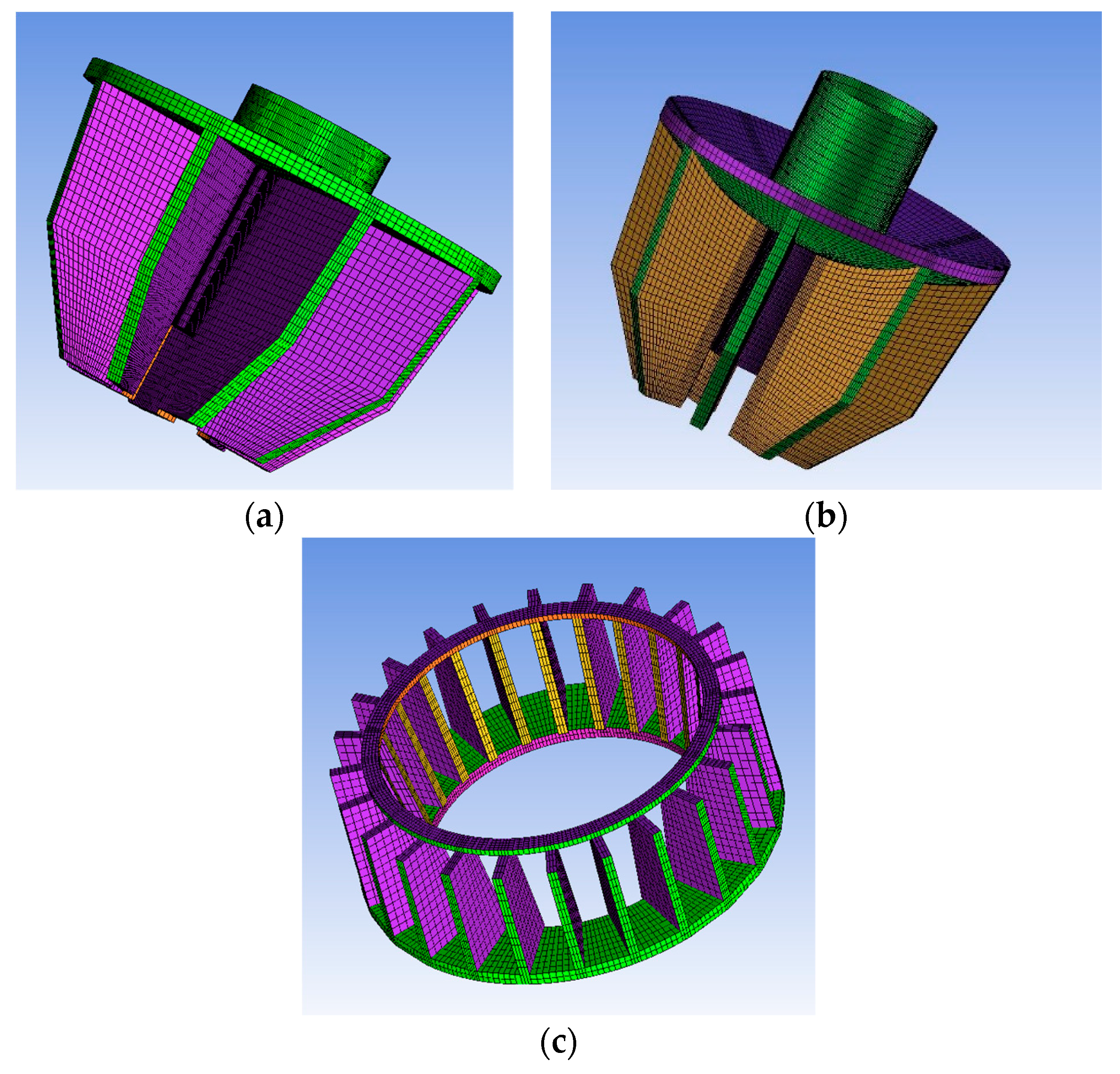
2.3. Geometry and CFD Model

This study was conducted using a mechanical agitated flotation cell with an effective volume of 680 m3 which is developed by BGRIMM. The large-scale flotation cell consists of a tank with an inner diameter of 11,000 mm and a tank height of 8500 mm. The speed of the impeller is about 7–9 m/s which is determined by mineral properties. The two types of impellers were introduced into the large-scale flotation cell in this study. The typical impeller features a horizontal impeller plate that has been proven to exhibit good performance in engineering applications (Figure 1). The newly designed impeller, namely the arc impeller, features a hyperbolic curve at the impeller plate for improving the performance of the large-scale flotation cell (Figure 2).
The numerical approaches for multiphase flow can be classified roughly into direct numerical simulation (DNS), Euler-Lagrange, and Euler-Euler models. The Euler-Euler approach is more practical and appropriate for the high gas volume fraction system, in which both phases are modeled by volume-averaged equations. The movement of the different continuous phases is described by solving the corresponding Reynolds averaged Navier-Stokes equations (Table 1).
The overall dimensions of the model were established, in which the model is meshed with hexahedral grids. As the geometrical size becomes increasingly large, the advantages of the structured mesh for reducing the mesh number, improving the mesh quality and reducing computational expense become obvious when compared with the unstructured mesh. The entire flotation cell mesh consists of 1.2 × 10⁶ units, as is illustrated in Figure 1. Mesh quality is above 0.4 using the criterion “determinant 2 × 2 × 2” in the ICEM software. Grid refinement tests showed less than 10% difference in the results predicted with finer meshes.
In the single phase simulation, the wall boundary condition is imposed on the top of the weir slip. However, in the multiphase flow simulation, the degassing boundary condition is imposed to allow only air to escape. Water is defined as a continuous fluid. Both air bubbles and mineral particles are considered to be dispersed fluids. The air bubbles have a uniform diameter of 2 mm. The drag force and surface tension are taken into account for the interface forces between the gas and liquid. The drag model uses the drag coefficient with 5. The other phase interactions, such as lift force, virtual mass force, turbulence dispersion force, and so on, are not considered in this study. The surface tension is 0.072 N·m−1. For solid and liquid phase, the mineral particles are defined as a dispersed solid, and the uniform diameter is 0.074 mm. The mass concentration is 36% (volume fraction 15%). The ore density is 2650 kg/m3 and the viscosity of the pulp is 3 mPa·s. The drag model of the Wen Yu model was selected for the interface force between the solid and liquid. The particle suspension may cause local high solid fractions, such as near the bottom of the tank. The Wen Yu model is valid for solid phase volume fractions up to 0.2. Thus, other phase interactions between solid and liquid were not considered. CFD simulations were implemented using computational fluid dynamics code CFX 14.0. It is suitable that the standard kε turbulence model is used in a flotation cell simulation for liquid phase. C1ε, C2ε and C3ε are the model constants in the turbulence kinetic energy transport equation and the turbulence energy dissipation transport equation in Table 3. The estimated Reynolds Number (ND2ρ/μ) would be 5.7 × 10⁶. This means it is fully turbulent in the major region of the flotation cell. For liquid and solid phase, the density difference and dispersed phase zero equation was selected.
In the CFD model of flotation cell is divided into multiple zones, such as the rotating impeller and stationary tank that are separated by interface boundaries. The Multiple Reference Frame model (MRF) approach was used to model the impeller rotating in the stationary tank. All equations are calculated by using high resolution and the residual RMS of equation was about 1 × 10⁻³ to 1 × 10⁻⁴. The velocity fluctuation of the monitoring point was about 10%. The detailed information about CFD is summarized in Table 4 and Table 5. The numerical simulations are conducted in National Supercomputer Center in Tianjin, China.

3. Results and Discussion

3.1. Hydrodynamics of the Large Flotation Cell
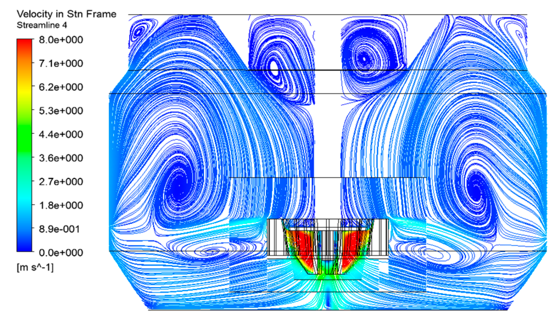
3.1.1. Flow Pattern

It is important to produce a suitable flow pattern in a large-scale flotation cell. Figure 2 illustrates the streamline at the center section of the flotation cell with a typical impeller. A circulating flow similar to that of the previous BGRIMM flotation cell was formed, which is a suitable fluid dynamics environment. The upper circulating flow is larger, with a relatively lower velocity than the lower circulating flow. The fluid is thrust away from the impeller blades and is pumped into the impeller zone due to the negative pressure. The turbulent dissipation rate reflects the flow intensity in the flotation. As is shown in Figure 3, the turbulence eddy dissipation at the center is high in the impeller zone and it is obviously low in other regions.

3.1.2. Gas Dispersion and Solid Suspension

Air dispersion and solid mixing are fundamental functions of flotation cells. Figure 4 presents the air dispersion at the center section of the flotation cell with a typical impeller, where the superficial velocity of the air is 2.5 cm/s. Air is well dispersed inside the cell, but the air holdup is quite low in the lower cell for buoyancy. Figure 5 shows the mixing of conventional particles with a size of 0.074 mm. There is a very low solid holdup region at the top of the flotation cell. This demonstrates that the mineral particles are brought to the top region and attached to the air bubbles in the actual flotation cell. Thus, high solid holdup appears under the impeller. This agrees with engineering practice where solid suspending is uniform in the major region of the flotation cell. The large-scale flotation cell developed produces excellent air dispersion and solid mixing.

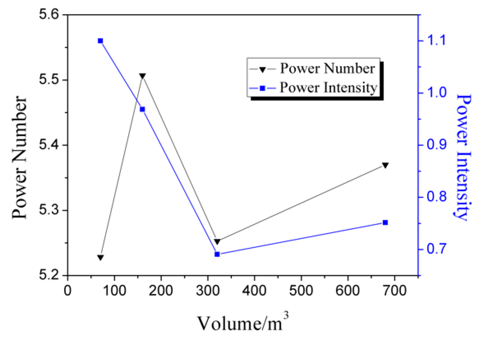
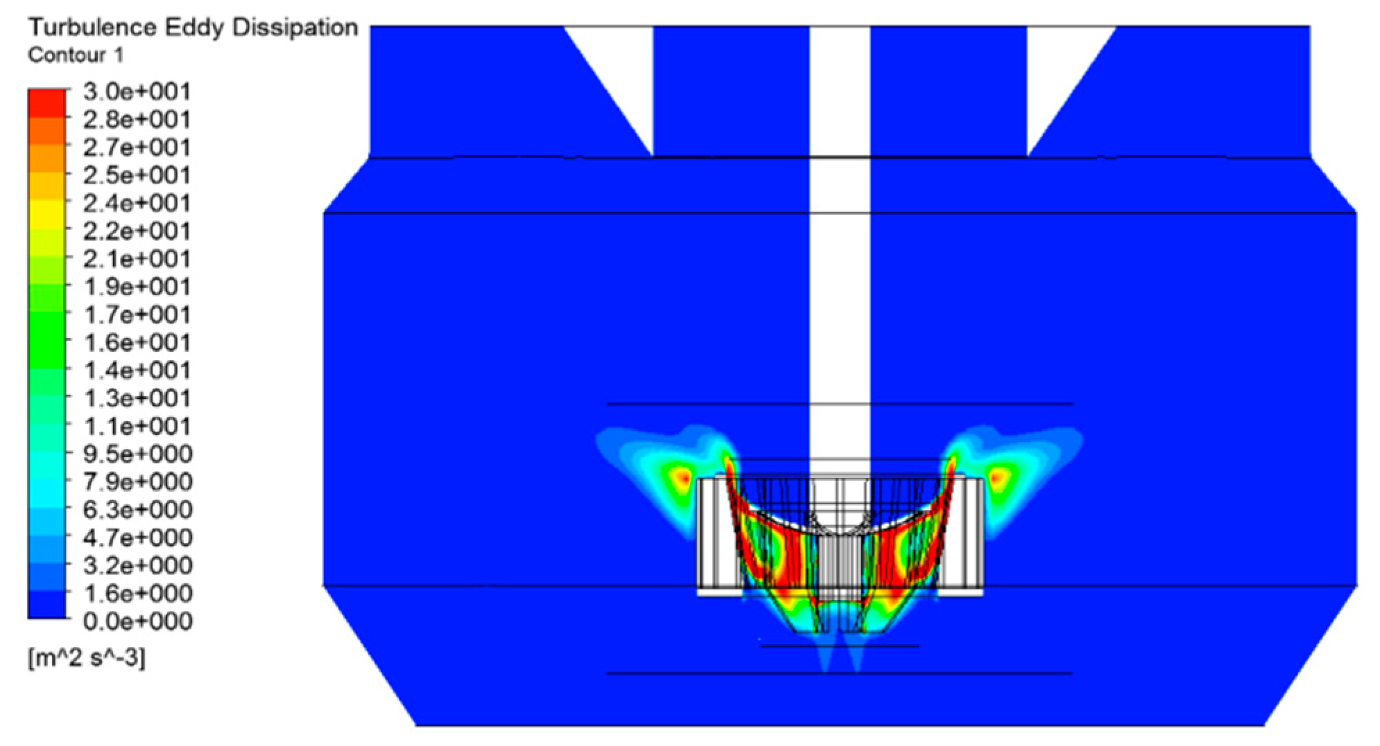
3.1.3. Analysis of Hydrodynamics Performances

Figure 6 shows the relationship between the flotation volume and power number or power intensity. For flotation cell volume ranging from 70 to 680 m3, the power number remines at about 5.4, illustrating a good balance between the volume and power during the cell scale-up. Generally, the power intensity decreases as the volume increases. This observation suggests the obvious advantages of reducing the power consumption and lowering the operation cost. The power intensity of the 680 m3 flotation cell is lightly higher than that of 320 m3 flotation cell. As shown in Figure 1c, a circular ring was positioned on top of the stator blades to maintain the structural stability where the stator blades are longer than those ever used in the previous cells. It is also very important to minimize the effect of the circular ring on the flow pattern. The new design may increase the power consumption of the large-scale flotation cell.
As illustrated in Figure 7, the circulation intensity decreases dramatically for cell volumes ranging from 70 to 130 m3. However, for cell sizes larger than 130 m3, the parameter varies a little and Fr number also changes slightly, which indicates the similarity of the serial flotation cells.
It is easy to see that the air flow number and the air capacity number only fluctuate slightly with scale-up in Figure 8. The air flow number is ~0.002, and the air capacity number is ~15%. The primary hydrodynamics numbers thus remained stable. In summary, the large BGRIMM flotation cell can maintain excellent hydrodynamic performance compared to the previous model, with different sizes that have been proven to be effective in engineering applications.

3.2. Comparison of the Typical Impeller and the Arc Impellers

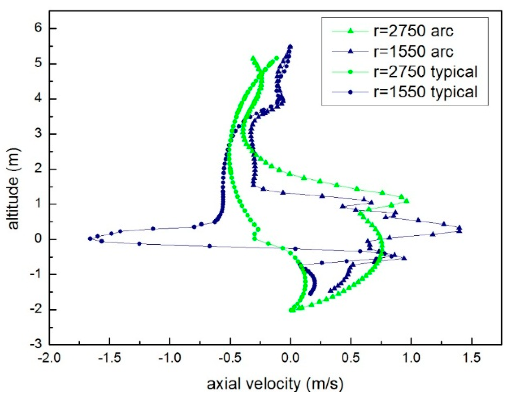
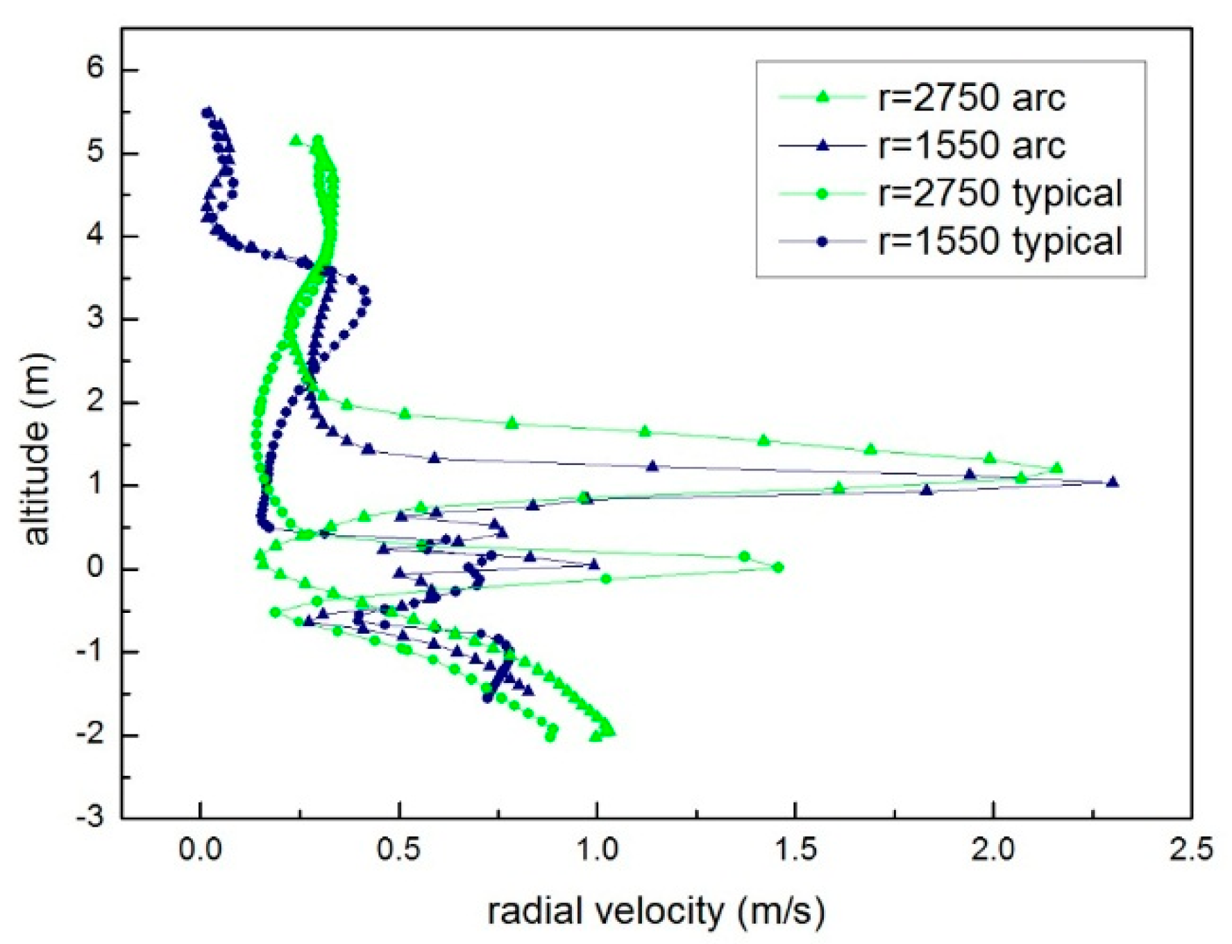
3.2.1. Comparison of Flow Pattern

The tank height of the large-scale flotation cell is relatively larger, even though the scale-up of the flotation cell is based on geometric similarity. The greater tank height may increase the probability of detachment when mineral particles are transported in the large-scale flotation cell. Thus, a newly developed impeller, the arc impeller, was employed. The streamline at the center section of the flotation cell with the arc impeller is illustrated in Figure 9 with the same operation parameters and structural parameters. A change in the circulating flow was readily observed. Compared with the typical impeller in Figure 2, the low circulating flow becomes larger and reaches the tank wall. The flow pumping out from the arc impeller is obviously inclined upward where the flow produced by the typical impeller is nearly horizontal. The lifting of the streamline would shorten the distance for the transportation distance of mineral particles. Figure 10 also shows the turbulence eddy dissipation profile at the center section in the flotation cell to that of the typical impeller. The overall distribution is similar to the typical impeller (Figure 3), where large turbulence eddy dissipation appears around the impeller. The difference between the typical impeller and the arc impeller is the turbulence eddy dissipation profile outside the impeller. It is demonstrated that a change in the shape of at the impeller plate affects the flow and turbulence in the flotation cell. The impeller plate with a hyperbolic curve that cause smooth flow along the curves results in the variations.
The line r = 1550 mm (the blue line) and r = 2750 mm (the green line) at the center longitudinal section was selected to show the different between the typical impeller and the arc impeller in Figure 11. Figure 12 and Figure 13 show the radial and axial velocity comparisons, respectively, between the two types of impellers at the blue line and green line. The vertical coordinates value of 0 m is the bottom of the impeller plate. At the blue line, the axial velocity of the arc impeller is upward around the impeller. Thus, the velocity of the typical impeller is downward. It seems the arc impeller could push the slurry higher. At the green line which is far away from impeller, the different is much smaller. The axial velocity of the typical impeller is a little downward which the value is negative around impeller. For radial velocity comparison, the arc impeller shows greater radial velocity at the blue line than the typical impeller.
Figure 14 shows the turbulence eddy dissipation (TED) comparisons. The turbulence eddy dissipation is very small at the green line because the position is away from the impeller. No changes could be detected between two types of impellers. The turbulence eddy peak of the arc impeller is larger than that of the typical impeller. It also indicates that the arc impeller could push slurry higher.

3.2.2. Comparison of Flotation Kinetics

The particle–bubble collision kernel (z1) is a key parameter for assessing the flotation kinetics. The collision kernel at the center section in the flotation cell with the typical impeller is indicated in Figure 15a. The collision kernel around the impeller and stator is larger than that at other regions of the flotation cell. The collision kernel for the arc impeller has a profile similar to that in the flotation cell in Figure 15b. It is also illustrated that outside of stator, the profile follows an upward tend r. The collision kernel maximum of the arc impeller is larger than that of the typical impeller. This means there will be a promotion in flotation kinetics.
The collision probability is a significant parameter that directly reflects the metallurgical performance. The collision probability at the center section of the flotation cell is shown in Figure 16. The collision probability profile reveals the zone where the mineral particles mainly collide with air bubbles. There is a high collision probability in the impeller chamber. The impeller-stator zone and the outflow around the stator are the main zones for particle–bubble collision because the turbulence kinetic energy is also high in these regions. Compared with the turbulence eddy dissipation profiles in Figure 3 and Figure 10, the profiles for the collision kernel and collision probability are similar in both the typical impeller and the arc impeller. Considering the flotation kinetics models proposed by Schubert and Bischofberger (Formulas (3) and (4)) [39], the turbulent eddy dissipation plays a critical role in the flotation kinetics. The difference in the collision probability profiles of the arc impeller is the same as the difference in the collision kernel profiles for the two types of impellers. The arc impeller gives rise to a higher collision probability than the typical impeller, leading to better metallurgical performance.
Figure 17 and Figure 18 show the collision kernel and the collision probability comparisons, respectively, between the two types of the impellers at the blue line and green line. The collision kernel peak of the two types of the impellers appears the position nearby the similar height of the impeller region. It indicates the impeller is the source for the collision between mineral and air bubbles. The collision kernel peak of the arc impeller is higher than that of the typical impeller both at the blue line and the green line. It is similar characteristics with the variation of the velocity and the turbulence eddy dissipation. The attenuation of the collision kernel from the blue line to the green line is larger in the arc impeller. The collision kernel peak of the arc impeller is obviously smaller than that of the typical impeller at the green line. The variation trend of the collision probability is similar with that of the collision kernel.
Table 6 summaries the comparison of the volume average parameters in the impeller region. The same trend could be observed about the volume average of the TED, z1 and Pc. Compared with the typical impeller, the volume average of the arc impeller is a little smaller. Thus, the torque of the typical impeller is also larger than that of the arc impeller. Considering the lifting of the slurry higher, the arc impeller would be favor for the coarse particle recovery which a lower turbulence flotation environment is needed.

4. Conclusions

Scale-up of the flotation cell is required for the solution processing of low-grade mineral ores worldwide. This study was conducted on the latest and largest flotation cell in China, having an effective volume 680 m3, developed by BGRIMM. Multiphase flow numerical simulations were performed to investigate the hydrodynamics and kinetics of the large-scale flotation cell for further optimization and improvement.
The circulating flow is similar to that of the previous flotation cell. Good air dispersion and solid mixing in the flotation cell were demonstrated. The hydrodynamic performance parameters were analyzed with scale-up of the cell. The variation of the hydrodynamic numbers, such as the power number (Np), the Froude number (Fr), the air flow number (Na), and so on, with the flotation cell volumes g follows trends similar to those of the previous cells of a different size that have been proven to be good for engineering applications.
To decrease the detachment of the mineral particles, a new type of impeller was developed (namely the arc impeller), where the impeller plate is a hyperbolic curve. The arc impeller expands and lifts the low circulating flow, thereby shortening the transportation distance of the mineral particles. Kinetic eddy dissipation plays a key role in determining the collision kernel and collision probability profile. The newly designed impeller leads to a higher collision probability than the typical impeller, leading to better flotation performance.

Author Contributions

conceptualization, Z.S. and S.S.; methodology, Z.S.; software, M.Z.; formal analysis, X.F.; investigation, M.Z. and D.H.; writing—original draft preparation, M.Z.

Funding

This work was supported by grants from the National Natural Science Foundation of China (No. 51474032 and No. 51674034).

Acknowledgments

The work was carried out at National Supercomputer Center in Tianjin, and the calculations were performed on TianHe-1 (A).

Conflicts of Interest

The authors declare no conflict of interest.

References

  1. Yianatos, J.B.; Larenas, J.M.; Moys, M.H.; Diaz, F.J. Short time mixing response in a big flotation cell. Int. J. Miner. Process. 2008, 89, 1–8. [Google Scholar] [CrossRef]
  2. Murphy, B.; Miettinen, T.; Yanez, A. Proceedings of the 27th International Mineral Processing Congress, IMPC 2014, Santiago, Chile, 20–24 October 2014; p. 265.
  3. Shen, Z.; Lu, S.; Yang, L. R&D and application of KYF large scale flotation cells developed by BGRIMM. Nonferrous Met. 2008, 4, 115–119. (In Chinese) [Google Scholar]
  4. Graul, R.; Nousiainen, M.; Yanez, A. Gas dispersion measurements in three outotec flotation cells: TankCell 1, e300 and e500. In Proceedings of the 27th International Mineral Processing Congress, IMPC 2014, Santiago, Chile, 20–24 October 2014; p. 265. [Google Scholar]
  5. Lelinski, D.; Yang, Y.; Caldwell, K.; Rahal, K.; Traczyk, F.; Olson, T.; Jespersen, M. Advances in FLSmidth flotation. In Proceedings of the 11th International Mineral Processing Conference, Santiago, Chile, 21–23 October 2015; p. 176. [Google Scholar]
  6. Mesa, D.; Brito-Parada, P.R. Scale-Up in Froth Flotation: A State-of-the-Art Review. Sep. Purif. Technol. 2019, 210, 950–962. [Google Scholar]
  7. Koh, P.T.L.; Manickam, M.; Schwarz, M.P. CDF simulation of bubble-particle collisions in mineral flotation cells. Miner. Eng. 2000, 13, 1455–1463. [Google Scholar] [CrossRef]
  8. Wang, G.; Ge, L.; Mitra, S.; Evans, G.M.; Joshi, J.B.; Chen, S. A review of CFD modelling studies on the flotation process. Miner. Eng. 2018, 127, 153–177. [Google Scholar] [CrossRef]
  9. Koh, P.T.L.; Schwarz, M.P. CFD modelling of bubble–particle collision rates and efficiencies in a flotation cell. Miner. Eng. 2003, 16, 1055–1059. [Google Scholar] [CrossRef]
  10. Xia, J.; Rinne, A.; Grönstrand, S. Effect of turbulence models on prediction of fluid flow in an Outotec flotation cell. Miner. Eng. 2009, 22, 880–885. [Google Scholar] [CrossRef]
  11. Salem-Said, A.-H.; Fayed, H.; Ragab, S. Numerical simulations of two-phase flow in a Dorr-Oliver flotation cell model. Minerals 2013, 3, 284–303. [Google Scholar] [CrossRef]
  12. Tiitinen, J.; Koskinen, K.; Ronkainen, S. Numerical modeling of an Outokumpu flotation cell. In Proceedings of the Centenary of Flotation Symposium, Brisbane, Australia, 6–9 June 2005; pp. 271–275. [Google Scholar]
  13. Shi, S.; Zhang, M.; Fan, X.; Chen, D. Experimental and computational analysis of the impeller angle in a flotation cell by PIV and CFD. Int. J. Miner. Process. 2015, 142, 2–9. [Google Scholar] [CrossRef]
  14. Koh, P.T.L.; Smith, L.K. The effect of stirring speed and induction time on flotation. Miner. Eng. 2011, 24, 442–448. [Google Scholar] [CrossRef]
  15. Nelson, M.G.; Lelinski, D. Hydrodynamic design of self-aerating flotation machines. Miner. Eng. 2000, 13, 991–998. [Google Scholar] [CrossRef]
  16. Arbiter, N.; Harris, C.C. Design and Operating Characteristics for Large Flotation Cells; SME Inc.: Littleton, CO, USA, 1979; p. 8. [Google Scholar]
  17. Brander, B. Dimensional analysis and scale-up in chemical engineering. Von m. Zlokarnik. Springer verlag, berlin 1991. 176 S., 51 Abb., geb., DM 38,–. Chem. Ing. Tech. 1993, 65, 457. [Google Scholar] [CrossRef]
  18. Yianatos, J.B.; Henríquez, F.D. Short-cut method for flotation rates modelling of industrial flotation banks. Miner. Eng. 2006, 19, 1336–1340. [Google Scholar] [CrossRef]
  19. Yianatos, J.; Contreras, F.; Morales, P.; Coddou, F.; Elgueta, H.; Ortíz, J. A novel scale-up approach for mechanical flotation cells. Miner. Eng. 2010, 23, 877–884. [Google Scholar] [CrossRef]
  20. Yianatos, J.; Carrasco, C.; Bergh, L.; Vinnett, L.; Torres, C. Modelling and simulation of rougher flotation circuits. Int. J. Miner. Process. 2012, 112, 63–70. [Google Scholar] [CrossRef]
  21. Yianatos, J.B. Fluid flow and kinetic modelling in flotation related processes columns and mechanically agitated cells—A review. Chem. Eng. Res. Des. 2007, 85, 1591–1603. [Google Scholar] [CrossRef]
  22. Yianatos, J. Flotation rate distribution in the collection zone of industrial cells. Miner. Eng. 2010, 23, 1030–1035. [Google Scholar] [CrossRef]
  23. Shen, Z. Principle and Technology of Flotation Machine; Metallurgical Industrial Press: Beijing, China, 2012. [Google Scholar]
  24. Shen, Z.; Zhang, Y.; Han, D.; Feng, T. Application of KYF-320 flotation cell. In Proceedings of the 27th International Mineral Processing Congress, IMPC 2014, Santiago, Chile, 20–24 October 2014; p. 178. [Google Scholar]
  25. Garcfa-Zuniga, H. Flotation recovery is an exponential function of its rate. In Proceedings of the 11th International Mineral Processing Conference, Santiago, Chile, 21–23 October 2015; Volume 47, pp. 83–86. [Google Scholar]
  26. Finch, J.A. Column flotation: A selected review—Part IV: Novel flotation devices. Miner. Eng. 1995, 8, 587–602. [Google Scholar] [CrossRef]
  27. Ahmed, N.; Jameson, G.J. Flotation kinetics. Miner. Process. Extr. Metall. Rev. 1989, 5, 77–99. [Google Scholar] [CrossRef]
  28. Salem-Said, A.; Fayed, H.; Ragab, S. CFD simulation of a Dorr-Oliver flotation cell. In Proceedings of the SME Annual Meeting and Exhibit, Denver, CO, USA, 24–27 February 2011. [Google Scholar]
  29. Tiitinen, J. Numerical modeling of a OK rotor-stator mixing device. In Proceedings of the European Symposium on Computer Aided Process Engineering, Kunming, China, 1–4 June 2003; Kraslawski, A., Turunen, I., Eds.; Volume 14, pp. 959–964. [Google Scholar]
  30. Shen, Z.; Chen, J. Flow Field Simulation and Its Applications; Science Press: Beijing, China, 2012. [Google Scholar]
  31. Fayed, H.; Ragab, S. Numerical simulations of two-phase flow in a self-aerated flotation machine and kinetics modeling. Minerals 2015, 5, 164–188. [Google Scholar] [CrossRef]
  32. Verrelli, D.I.; Koh, P.T.L.; Nguyen, A.V. Particle–bubble interaction and attachment in flotation. Chem. Eng. Sci. 2011, 66, 5910–5921. [Google Scholar] [CrossRef]
  33. Koh, P.T.L.; Schwarz, M.P. Modelling attachment rates of multi-sized bubbles with particles in a flotation cell. Miner. Eng. 2008, 21, 989–993. [Google Scholar] [CrossRef]
  34. Koh, P.T.L.; Schwarz, M.P. CFD modelling of bubble–particle attachments in flotation cells. Miner. Eng. 2006, 19, 619–626. [Google Scholar] [CrossRef]
  35. Koh, P.T.L.; Schwarz, M.P. CFD model of a self-aerating flotation cell. Int. J. Miner. Process. 2007, 85, 16–24. [Google Scholar] [CrossRef] [Green Version]
  36. Zhou, J.; Song, T.; Shen, Z. CFD simulation of gas-liquid flow in a large scale flotation cell. J. Comput. Multiph. Flows 2010, 2, 145–150. [Google Scholar] [CrossRef]
  37. Abrahamson, J. Collision rates of small particles in a vigorously turbulent fluid. Chem. Eng. Sci. 1975, 30, 1371–1379. [Google Scholar] [CrossRef]
  38. Schubert, H.; Bischofberger, C. On the optimization of hydrodynamics in flotation processes. In Proceedings of the 13th International Mineral Processing Congress, Warsaw, Poland, 4–9 June 1979; Volume 2, pp. 1261–1285. [Google Scholar]
  39. Yoon, R.H.; Luttrell, G.H. The effect of bubble size on fine particle flotation. Miner. Process. Extr. Metall. Rev. 1989, 5, 101–122. [Google Scholar] [CrossRef]
Figure 1. (a) The mesh of the typical impeller; (b) The mesh of the arc impeller; (c) The mesh of the stator.
Minerals 09 00079 g001
Figure 2. Velocity streamline profile at the center section.
Minerals 09 00079 g002
Figure 3. Turbulence eddy dissipation at the center section.
Minerals 09 00079 g003
Figure 4. Air volume fraction profile.
Minerals 09 00079 g004
Figure 5. Solid volume fraction profile.
Minerals 09 00079 g005
Figure 6. The relationship of volume, power number Np and circulation intensity.
Minerals 09 00079 g006
Figure 7. The relationship of volume, power intensity, air flow number Na, and Froude number Fr.
Minerals 09 00079 g007
Figure 8. The relationship of volume, power intensity, air flow number Na.
Minerals 09 00079 g008
Figure 9. Velocity streamline profile at the center section in the flotation cell with the typical impeller.
Minerals 09 00079 g009
Figure 10. Turbulence eddy dissipation at the center section in the flotation cell with the arc impeller.
Minerals 09 00079 g010
Figure 11. The line at the centre longitudinal section.
Minerals 09 00079 g011
Figure 12. Axial velocity comparisons between two types of the impeller at the blue line and green line.
Minerals 09 00079 g012
Figure 13. Radial velocity comparisons between two types of the impeller at the blue line and green line.
Minerals 09 00079 g013
Figure 14. Turbulence eddy dissipation comparisons between two types of the impeller at the blue line and green line.
Minerals 09 00079 g014
Figure 15. The collision kernel profile at the center section: (a) The typical impeller; (b) The arc impeller.
Minerals 09 00079 g015
Figure 16. The collision probability profile at the center section in the flotation cell: (a) The typical impeller; (b) The arc impeller.
Minerals 09 00079 g016
Figure 17. The collision kernel comparisons between two types of the impeller at the blue line and green line.
Minerals 09 00079 g017
Figure 18. The collision probability comparisons between two types of the impeller at the blue line and green line.
Minerals 09 00079 g018
Table 1. The summary of the computational fluid dynamics (CFD) simulation and scale-up of flotation cells.
ResearchCommentAuthor/Organization
Large flotation applicationTank cell flotation cells scale-up from 60–620 m3 in 1960s–now; The new flotation force impeller was developedOutotec company
Dorroliver/Wemco flotation cells scale up to 660 m3/300 m3. The next step impeller and stator was developedFLSmidth company
KFY/JJF flotation cells scale up to 680 m3/320 m3 from 1990–2018. The arc impeller and other newly designed impeller are developingBGRIMM company
Scale-up method of flotation cellhydrodynamic numbers are established to analyze the hydrodynamics characteristics in Wemco flotation cellNelson [15]
Propose seven important hydrodynamic numbers to scaling up Arbiter [16]
summarized 24 dimensionless numbers for mineral processing and chemical engineeringZlokarnik [17]
Based on the RTD research to scale up and optimize large flotation cellYianatos et al. [18,19,20,22]
Scale-up method of BGRIMM flotation cell based on four scale-up numbers Shen et al. [23,24]
Kinetic modelR(t) = Rmax(1 − ekt)Garcfa-Zuniga [25]
R = R R c R f R c R f + ( 1 R c ) Dobby & Finch [26]
R ( t ) = R m a x 0 ( 1 e k t ) f ( k ) E ( t ) d k d t Yianatos [1,21]
d N p d t = k N p Ahmed and Jameson [27]
CFD modelSingle phase:
Continuity:
ρ t + ρ u = 0
Momentum:
ρ u t + ρ u u = p + ( μ L , i + μ T , i ) ( u i + ( u i ) T + ρ g
Wang et al. [8]
Euler-Euler:
Continuity:
( α i ρ i ) t + α i ρ i u i = S i
Monentum:
( α i ρ i u i ) t + ( α i ρ i u i u i ) = [ α i ( μ L , i + μ T , i ) ( u i + ( u i ) T ) ] + α i ( f i p i ) + F i + S i u i
F i = F d + F A + F L + F T + F o t h e r
Euler-Lagrangian:
Continuity:
ρ t + ρ u = 0
Monentum:
ρ u t + ρ u u = p + ( μ L , i + μ T , i ) ( u i + ( u i ) T ) + ρ g
Continuity:
( α l ρ ) t + α l ρ u = 0
Monentum:
( α l ρ u ) t + α l ρ u u = α l p + α l ( μ L , i + μ T , i ) ( u i + ( u i ) T ) + α l ρ g
Particle or bubble motion:
m i d u i d t = F d + F p + F G + F o t h e r
CFD simulation Flow pattern research including mixing, air bubbles dispersion and so on, such as air forced flotation cell of TankCell, KYF, Dorr-Oliver flotation cellSalem-Said et al. [28];
Tiitinen [12,29];
Xia et al. [10];
Shen et al. [30];
Self-induced flotation cell research on air suction, flow patternFayed and Ragab [31]
Particle-air bubbles collision, adherin, detachment research predict the metallurgical performanceKoh and Schwarz [7,32,33,34,35]
Recovery simulation would be compared with experimentKoh and Schwarz [14]
CFD model verification using experimental dataShi et al. [13]
Optimized of flotation cell of structureZhou et al. [36]
where Rmax (R): the theoretical maximum recovery achievable, considering the equipment effciency and mineral liberation; t: time; k: flotation constant; Rc: the recovery from the collection zone; Rf: the recovery from froth zone; E(t): the residence time distribution; f(k): the flotation rate distribution; Np is the number of free particles in the pulp phase; u: velocity vector; ρ: density; t: time; p: pressure; g: gravity vector; α: phase volume fraction; μ: dynamic viscosity; F: inter-phase force; Fd: the drag force; FA: the virtual mass force; FL: the lift force; FT: the turbulence dispersion force; Fother: the other force; f: body force; Si: source term. The subscript: i: represents for each phase; l: liquid; g: gas; d: drag; p: pressure gradient; G: gravity.
Table 2. The typical hydrodynamic performance parameters for flotation cell.
ParameterDefinition
Power Number, NpP/ρN3D5
Power intensityP/V
Circulation IntensityQr/ND3
Froude Number, FrN2D/g
Air Capacity Number, CaQ/ND3
Air Flow Number, NaQ/AcVt
where P: the net power input in the water system; ρ: density; N: rotation; D: the diameter of the cell; g: the acceleration due to gravity; V: the effective volume of the flotation cell; Q (m3/s): the gas volumetric flow; Qr: the circulation volume of the impeller; Ac: the area of the cross section in the flotation cell; Vt: the velocity maximum of the impeller.
Table 3. Turbulence model constants.
ConstantCμC1εC2εC3εkσε
Value0.091.441.921.00.4187 k 2 ( C 2 ε C 1 ε ) C μ 0.5
Table 4. CFD simulation settings.
Single PhaseMultiphase
Mesh typeStructure mesh
Analysis typeSteady stead
PhaseWater for continous fluid; air for dispersion fluid; solid for dispersion solid
ModelK–ε model for liquid; dispersed phase zero equation for liquid
Multiple zoneThe Multiple Reference Frame model (MFR)
Table 5. CFD simulation initial and boundary conditions.
Single PhaseMultiphase
Mesh zoneMove zone with rotating of 90 rpm including impeller; stationary zone including stator and tank
InterfaceConnecting move zone and stationary zone with GGI
MaterialsWater; air bubbles of 2 mm, particles of 0.074 mm, 2650 kg/m3, 3 mPa·s
BoundaryWall at the top of tank;
others as wall
Degassing at the top of tank as air outlet;
Air inlet at the impeller; others as wall
Initial100% of water; Pressure 1 atm; velocity 0; Turbluence: medium (intensity 5%)The simulation result of the single phase;
Gas liquid simulation: the volume fraction of water 1, the volume fraction of gas 0;
Gas–liquid–solid simulation: 15% of solid, 85% of water, no air for initial
SolutionHigh resolution in CFX software
Table 6. Critical Parameters Comparison.
Volume Average of TED in Rotor Zone, m2/s3Volume Average of z1 in Rotor ZoneVolume Average of Pc in Rotor Zone, %Torque of Rotor Zone, N·m
TypicalArcTypicalArcTypicalArcTypicalArc
33.017.22.4 × 10−51.9 × 10−531.925.454,280.646,859.3

