
Frequency Response of Higher-Order Shear-Deformable Multilayered Angle-Ply Cylindrical Shells

Abstract
1. Introduction
2. Problem Formulation
2.1. Displacement Field
2.2. Strains and Stress Components
2.3. Equilibrium Equations
- .
- , and is the material density of the -th layer.
- And
- , a distant coordinate, and ; , a frequency parameter;
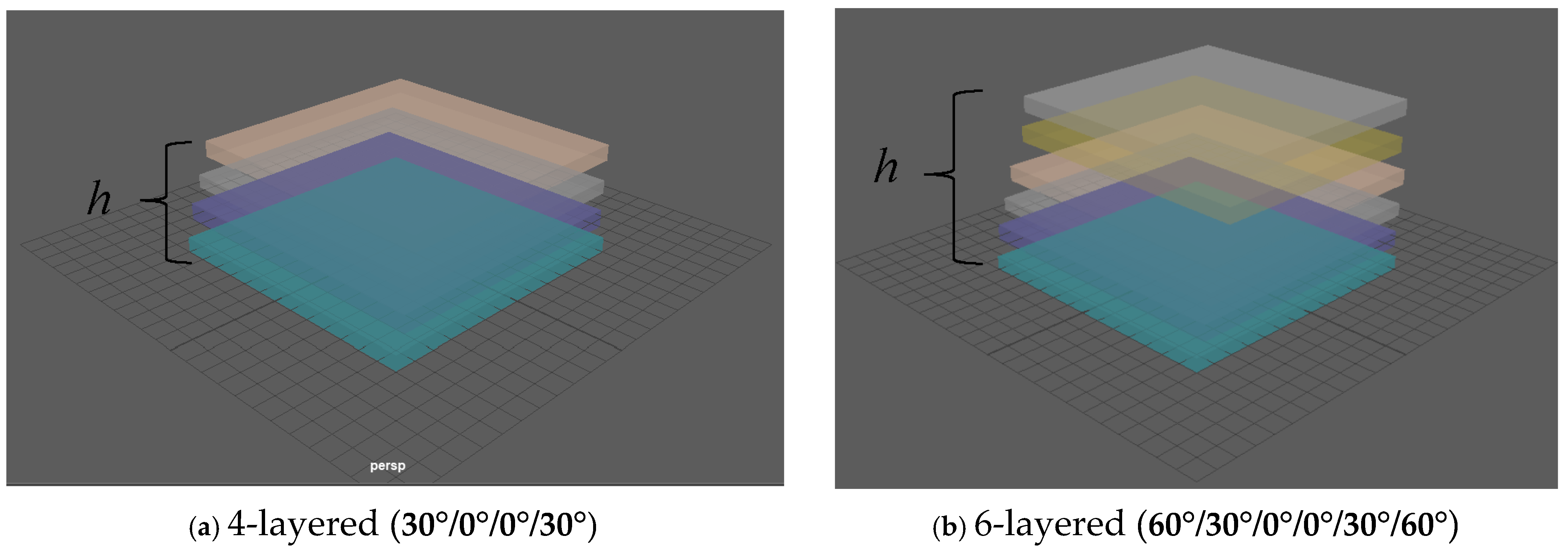
- , a length parameter; , ratio of total thickness to radius;
- , relative layer thickness of the -th layer
- where is the thickness of the kth layer.
2.4. Spline Approximation
- (S-S): both ends are simply supported.
3. Discussion on Result Outcomes
4. Conclusions
Funding
Data Availability Statement
Acknowledgments
Conflicts of Interest
References
- He, D.; Shi, D.; Wang, Q.; Ma, C. Free vibration characteristics and wave propagation analysis in nonlocal functionally graded cylindrical nanoshell using wave-based method. J. Braz. Soc. Mech. Sci. Eng. 2021, 43, 1–24. [Google Scholar] [CrossRef]
- Mercan, K.; Baltacıoglu, A.K.; Civalek, Ö. Free vibration of laminated and FGM/CNT composites annular thick plates with shear deformation by discrete singular convolution method. Compos. Struct. 2018, 186, 139–153. [Google Scholar] [CrossRef]
- Nguyen, V.C.; Tran, H.Q.; Tran, M.T. Nonlinear free vibration analysis of multi-directional functionally graded porous sandwich plates. Thin-Walled Struct. 2024, 203, 112204. [Google Scholar] [CrossRef]
- Hu, B.; Liu, J.; Wang, Y.; Zhang, B.; Shen, H. Wave propagation analysis of functionally graded graphene-reinforced piezoelectric sandwich nanoplates via nonlocal strain gradient theory. Int. J. Struct. Stab. Dyn. 2023, 23, 2350070. [Google Scholar] [CrossRef]
- Arefi, M.; Moghaddam, S.K.; Bidgoli EM, R.; Kiani, M.; Civalek, O. Analysis of graphene nanoplatelet reinforced cylindrical shell subjected to thermo-mechanical loads. Compos. Struct. 2021, 255, 112924. [Google Scholar] [CrossRef]
- Reddy, J.N. A Simple Higher-Order Theory for Laminated Composite Plates. J. Appl. Mech. 1984, 51, 745–752. [Google Scholar] [CrossRef]
- Reddy, J.N.; Liu, C.F. A Higher-Order Shear Deformation Thoery Of Laminated Elastic Shells. Int. J. Eng. Sci. 1985, 23, 319–330. [Google Scholar] [CrossRef]
- Vinson, J.R. Sandwich structures. Appl. Mech. Rev. 2001, 54, 201–214. [Google Scholar] [CrossRef]
- Noor, A.K.; Burton, W.S.; Bert, C.W. Computational models for sandwich panels and shells. Appl. Mech. Rev. 1996, 49, 155–199. [Google Scholar] [CrossRef]
- Javed, S. Free vibration characteristic of laminated conical shells based on higher-order shear deformation theory. Compos. Struct. 2018, 204, 80–87. [Google Scholar] [CrossRef]
- Javed, S. Conical-shaped shells of non-uniform thickness vibration analysis using higher-order shear deformation theory. Symmetry 2024, 16, 620. [Google Scholar] [CrossRef]
- Javed, S. A numerical solution of symmetric angle ply plates using higher-order shear deformation theory. Symmetry 2023, 15, 767. [Google Scholar] [CrossRef]
- Roy, S.; Nath Thakur, S.; Ray, C. Investigation on free vibration behavior of laminated angle ply shell with numerical validation. Mech. Based Des. Struct. Mach. 2024, 52, 1351–1376. [Google Scholar] [CrossRef]
- Peng, Q.; Wang, Q.; Chen, Z.; Zhong, R.; Liu, T.; Qin, B. Dynamic stiffness formulation for free vibration analysis of rotating cross-ply laminated combined elliptical-cylindrical-conical shell. Ocean Eng. 2023, 269, 113486. [Google Scholar] [CrossRef]
- Shinde, B.M.; Sayyad, A.S. A new higher-order shear and normal deformation theory for the free vibration analysis of laminated shells. Mech. Adv. Compos. Struct. 2022, 9, 89–104. [Google Scholar]
- Lore, S.; Sarangan, S.; Singh, B.N. Nonlinear free vibration analysis of laminated composite plates and shell panels using non-polynomial higher-order shear deformation theory. Mech. Adv. Mater. Struct. 2022, 29, 5608–5623. [Google Scholar] [CrossRef]
- Tong, B.; Zhang, Z.; Zhao, C.; Qu, D. Free vibration analysis of fiber-reinforced composite multilayer cylindrical shells under hydrostatic pressure. J. Sound Vib. 2024, 587, 118511. [Google Scholar] [CrossRef]
- Parvez, M.T.; Khan, A.H. Influence of geometric imperfections on the nonlinear forced vibration characteristics and stability of laminated angle-ply composite conical shells. Compos. Struct. 2022, 291, 115555. [Google Scholar] [CrossRef]
- Bochkarev, S.A.; Lekomtsev, S.V.; Matveenko, V.P. Natural vibrations of composite cylindrical shells partially filled with fluid. Vestn. St. Petersburg Univ. Math. 2023, 56, 435–445. [Google Scholar] [CrossRef]
- Gulizzi, V.; Benedetti, I.; Milazzo, A. High-order accurate transient and free-vibration analysis of plates and shells. J. Sound Vib. 2024, 587, 118479. [Google Scholar] [CrossRef]
- Li, L.; Cheng, L.; Liu, W.; Yu, X. Effect of anisotropic stiffness degradation on the forced vibration of cylindrical shells. Thin-Walled Struct. 2023, 193, 111255. [Google Scholar] [CrossRef]
- Eipakchi, H.; Mahboubi Nasrekani, F. A closed-form solution for asymmetric free vibration analysis of composite cylindrical shells with metamaterial honeycomb core layer based on shear deformation theory. Mech. Based Des. Struct. Mach. 2023, 51, 6513–6531. [Google Scholar] [CrossRef]
- Nguyen, V.L.; Tran, M.T.; Limkatanyu, S.; Mohammad-Sedighi, H.; Rungamornrat, J. Reddy’s third-order shear deformation shell theory for free vibration analysis of rotating stiffened advanced nanocomposite toroidal shell segments in thermal environments. Acta Mech. 2022, 233, 4659–4684. [Google Scholar] [CrossRef]
- Kim, J.; Kim, K.; Kim, K.; Hong, K.; Paek, C. Free Vibration Analysis of Cross-Ply Laminated Conical Shell, Cylindrical Shell, and Annular Plate with Variable Thickness Using the Haar Wavelet Discretization Method. Shock Vib. 2022, 2022, 6399675. [Google Scholar] [CrossRef]
- Attia, A.; Berrabah, A.T.; Bourada, F.; Bousahla, A.A.; Tounsi, A.; Salem, M.A.; Cuong-Le, T. Free Vibration Analysis of Thick Laminated Composite Shells Using Analytical and Finite Element Method. J. Vib. Eng. Technol. 2024, 12, 7711–7728. [Google Scholar] [CrossRef]
- Chen, Z.; Qin, B.; Wang, Q.; Zhong, R.; Wang, A. Vibration analysis of laminated open cylindrical shell coupled with rectangular plates. Compos. Struct. 2022, 292, 115607. [Google Scholar] [CrossRef]
- Jahanbazi, R.; Kiani, Y.; Beni, Y.T. Free vibration behaviour of composite laminated skew cylindrical shells reinforced with graphene platelets. In Structures; Elsevier: Amsterdam, The Netherlands, 2024; Volume 61, p. 106074. [Google Scholar]
- Ma, J.; Gao, H. Free vibration analysis of hybrid laminated thin-walled cylindrical shells containing multilayer FG-CNTRC plies. Acta Mech. 2024, 235, 7711–7731. [Google Scholar] [CrossRef]
- Ghassabi, A.A.; Razgordanisharahi, A.; Sendur, G.K.; Kiani, Y.; Hellmich, C. An exact analytical method for free vibration analysis of FG-GPLRC sector cylindrical shells under Levy-type boundary conditions. Acta Mech. 2024, 235, 6849–6865. [Google Scholar] [CrossRef]
- Guo, C.; Liu, T.; Bin, Q.; Wang, Q.; Wang, A. Free vibration analysis of coupled structures of laminated composite conical, cylindrical and spherical shells based on the spectral-Tchebychev technique. Compos. Struct. 2022, 281, 114965. [Google Scholar] [CrossRef]
- Nguyen, V.L.; Limkatanyu, S.; Thai, H.T.; Rungamornrat, J. Simple first-order shear deformation theory for free vibration of FGP-GPLRC spherical shell segments. Mech. Adv. Mater. Struct. 2024, 31, 6944–6961. [Google Scholar] [CrossRef]
- Garg, A.; Li, L. Data-driven uncertainty quantification and sensitivity studies in free vibration behavior of bio-inspired helicoidal laminated composite cylindrical shells. Mech. Adv. Mater. Struct. 2024, 1–16. [Google Scholar] [CrossRef]
- Chen, W.; Luo, W.M.; Chen, S.Y.; Peng, L.X. A FSDT meshfree method for free vibration analysis of arbitrary laminated composite shells and spatial structures. Compos. Struct. 2022, 279, 114763. [Google Scholar] [CrossRef]
- Khorasani, M.; Lampani, L.; Dimitri, R.; Tornabene, F. Thermomechanical buckling analysis of the E&P-FGM beams integrated by nanocomposite supports immersed in a hygrothermal environment. Molecules 2021, 26, 6594. [Google Scholar] [CrossRef] [PubMed]
- Khorasani, M.; Elahi, H.; Eugeni, M.; Lampani, L.; Civalek, O. Vibration of FG porous three-layered beams equipped by agglomerated nanocomposite patches resting on Vlasov’s foundation. Transp. Porous Media 2022, 142, 157–186. [Google Scholar] [CrossRef]
- Khorasani, M.; Lampani, L.; Tounsi, A. A refined vibrational analysis of the FGM porous type beams resting on the silica aerogel substrate. Steel Compos. Struct. 2023, 47, 633–644. [Google Scholar]
- Khorasani, M.; Soleimani-Javid, Z.; Arshid, E.; Lampani, L.; Civalek, Ö. Thermo-elastic buckling of honeycomb micro plates integrated with FG-GNPs reinforced Epoxy skins with stretching effect. Compos. Struct. 2021, 258, 113430. [Google Scholar] [CrossRef]
- Reddy, J.N. Mechanics of Composite Plates and Shells: Theory and Analysis, 2nd ed.; CRC Press: Boca Raton, FL, USA, 2004. [Google Scholar]
- Javed, S.; Viswanathan, K.K.; Aziz, Z.A.; Karthik, K.; Lee, J.H. Vibration of antisymmetric angle-ply laminated plates under higher order shear theory. Steel Compos. Struct 2016, 22, 1281–1299. [Google Scholar] [CrossRef]
- Saad ALNuwairan, M.; Javed, S. Free Vibration of Composite Cylindrical Shells Based on Third-Order Shear Deformation Theory. J. Math. 2021, 2021, 3792164. [Google Scholar] [CrossRef]


| a/h | Layers | Angle-Ply Lamination Scheme | Fundamental Frequency | |||||||||
|---|---|---|---|---|---|---|---|---|---|---|---|---|
| R/a = 1 | R/a = 2 | R/a = 3 | R/a = 4 | R/a = 5 | ||||||||
| 10 | Ref. Roy et al. [13] | Present | Ref. Roy et al. [13] | Present | Ref. Roy et al. [13] | Present | Ref. Roy et al. [13] | Present | Ref. Roy et al. [13] | Present | ||
| 3 | −45°/45°,/−45°, | 1411.56 | 1411.41 | 1172.47 | 1172.32 | 1123.44 | 1123. 32 | 1105.607 | 1105.54 | 1097.134 | 1097.02 | |
| 4 | [−45°/45°]s | 1062.66 | 1062.52 | 893.92 | 893.83 | 861.35 | 861.22 | 850.00 | 850.00 | 844.815 | 844.74 | |
| 5 | −45°/45°/−45°/45°/−45° | 839.27 | 839.11 | 703.85 | 703.71 | 677.96 | 677.84 | 669.05 | 669.04 | 665.033 | 665.02 | |
| 6 | [−45°/45°/−45°]s | 668.23 | 668.11 | 556.93 | 556.81 | 536.92 | 536.82 | 530.49 | 530.35 | 527.82 | 527.71 | |
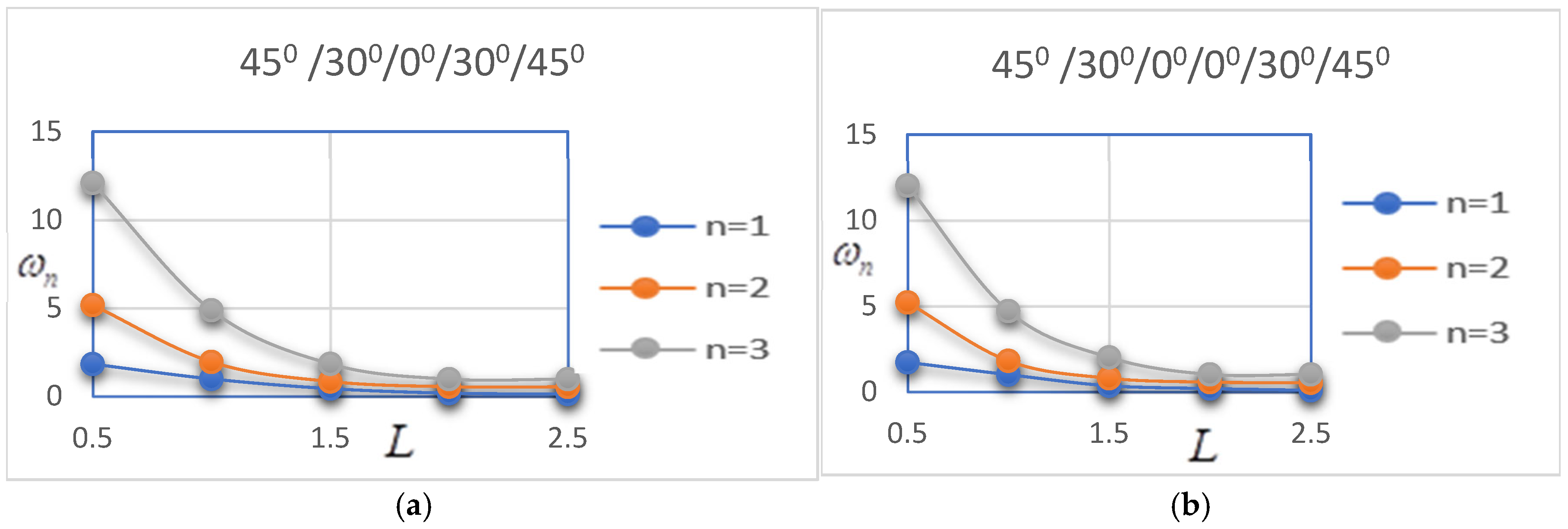
| 60°/0°/60° | 60°/0°/0°/60° | 60°/30°/0°/30°/60° | 60°/30°/0°/0°/30°/60° | |
|---|---|---|---|---|
| 0.5 | 2.99357 | 2.62157 | 1.91732 | 2.67609 |
| 1 | 1.19244 | 1.32572 | 0.999881 | 1.0431 |
| 1.5 | 0.365161 | 0.30223 | 0.431398 | 0.362887 |
| 2 | 0.174763 | 0.102356 | 0.195176 | 0.208656 |
| 2.5 | 0.091274 | 0.08912 | 0.093216 | 0.081422 |
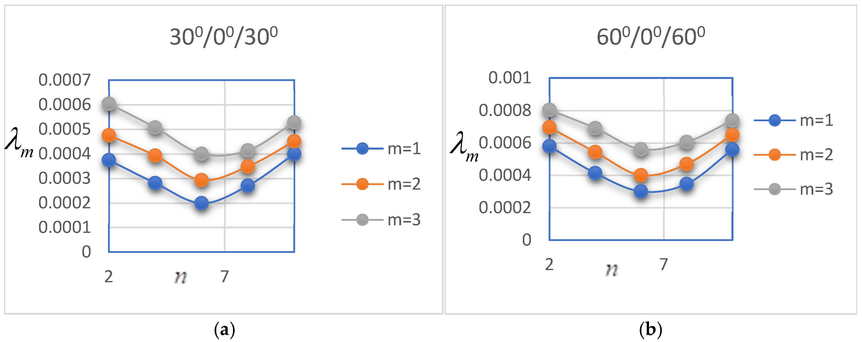
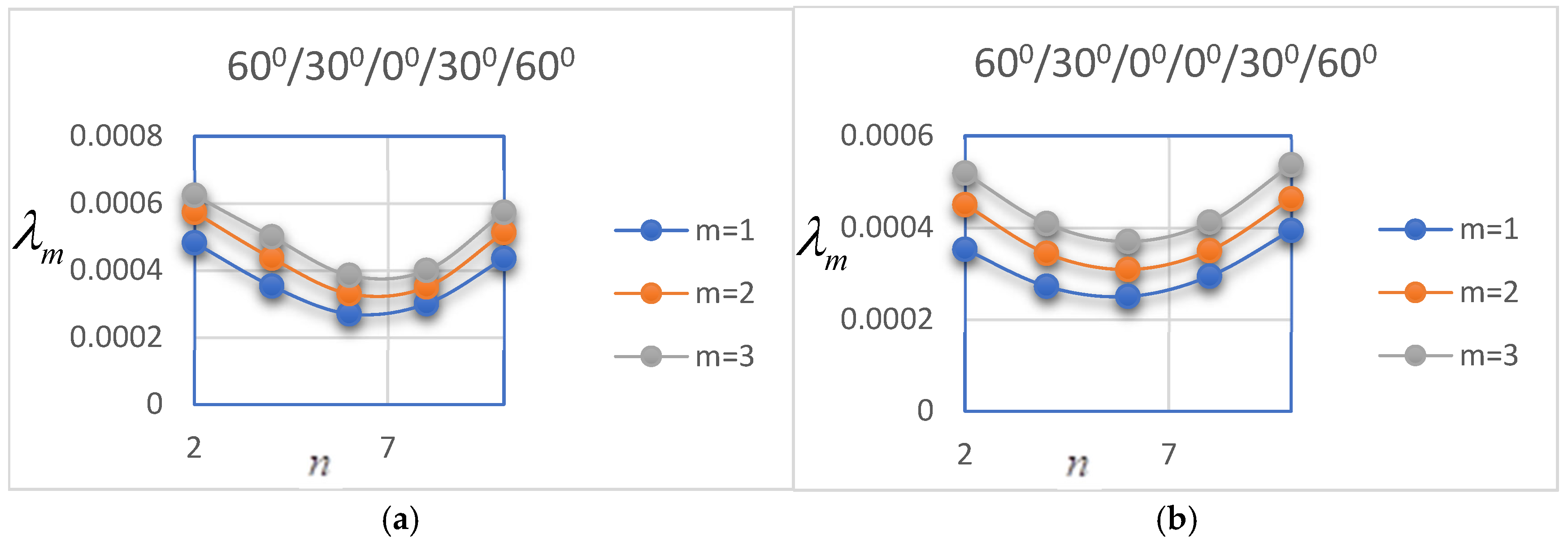
| 30°/0°/30° | 30°/0°/0°/30° | 60°/30°/0°/30°/60° | 60°/30°/0°/0°/30°/60° | |
|---|---|---|---|---|
| 2 | 0.0004 | 0.0004 | 0.00048 | 0.0004 |
| 4 | 0.00028 | 0.00031 | 0.00035 | 0.00027 |
| 6 | 0.00019 | 0.00027 | 0.00027 | 0.0003 |
| 8 | 0.00027 | 0.00032 | 0.0003 | 0.0003 |
| 10 | 0.00039 | 0.00042 | 0.000435 | 0.0004 |
Disclaimer/Publisher’s Note: The statements, opinions and data contained in all publications are solely those of the individual author(s) and contributor(s) and not of MDPI and/or the editor(s). MDPI and/or the editor(s) disclaim responsibility for any injury to people or property resulting from any ideas, methods, instructions or products referred to in the content. |
© 2025 by the author. Licensee MDPI, Basel, Switzerland. This article is an open access article distributed under the terms and conditions of the Creative Commons Attribution (CC BY) license (https://creativecommons.org/licenses/by/4.0/).
Share and Cite
Javed, S. Frequency Response of Higher-Order Shear-Deformable Multilayered Angle-Ply Cylindrical Shells. Axioms 2025, 14, 172. https://doi.org/10.3390/axioms14030172
Javed S. Frequency Response of Higher-Order Shear-Deformable Multilayered Angle-Ply Cylindrical Shells. Axioms. 2025; 14(3):172. https://doi.org/10.3390/axioms14030172
Chicago/Turabian StyleJaved, Saira. 2025. "Frequency Response of Higher-Order Shear-Deformable Multilayered Angle-Ply Cylindrical Shells" Axioms 14, no. 3: 172. https://doi.org/10.3390/axioms14030172
APA StyleJaved, S. (2025). Frequency Response of Higher-Order Shear-Deformable Multilayered Angle-Ply Cylindrical Shells. Axioms, 14(3), 172. https://doi.org/10.3390/axioms14030172