Article

Unmanned Aerial Vehicles Motion Control with Fuzzy Tuning of Cascaded-PID Gains †

by
Fabio A. A. Andrade
1,2,*,
Ihannah P. Guedes
3,
Guilherme F. Carvalho
3,
Alessandro R. L. Zachi
3,
Diego B. Haddad
3,
Luciana F. Almeida
3,
Aurélio G. de Melo
4 and
Milena F. Pinto
3
1
Department of Microsystems, Faculty of Technology, Natural Sciences and Maritime Sciences, University of South-Eastern Norway (USN), 3184 Borre, Norway
2
NORCE Norwegian Research Centre, 5838 Bergen, Norway
3
Federal Center of Technological Education of Rio de Janeiro (CEFET/RJ), Rio de Janeiro 20271-110, Brazil
4
Department of Electrical Engineering, Federal University of Juiz de Fora, Juiz de Fora 36036-900, Brazil
*
Author to whom correspondence should be addressed.
This paper is an extended version of the conference paper published in: Carvalho, G.; Guedes, I.; Pinto, M.; Zachi, A.; Almeida, L.; Andrade, F.; Melo, A.G. Hybrid PID-Fuzzy controller for autonomous UAV stabilization. In Proceedings of the 2021 14th IEEE International Conference on Industry Applications (INDUSCON), São Paulo, Brazil, 16–18 August 2021; IEEE: Piscataway, NJ, USA, 2021; pp. 1296–1302.
Machines 2022, 10(1), 12; https://doi.org/10.3390/machines10010012
Submission received: 18 November 2021 / Revised: 15 December 2021 / Accepted: 20 December 2021 / Published: 23 December 2021
(This article belongs to the Special Issue Industrial Applications: New Solutions for the New Era)

Abstract

:
One of the main challenges of maneuvering an Unmanned Aerial Vehicle (UAV) to keep a stabilized flight is dealing with its fast and highly coupled nonlinear dynamics. There are several solutions in the literature, but most of them require fine-tuning of the parameters. In order to avoid the exhaustive tuning procedures, this work employs a Fuzzy Logic strategy for online tuning of the PID gains of the UAV motion controller. A Cascaded-PID scheme is proposed, in which velocity commands are calculated and sent to the flight control unit from a given target desired position (waypoint). Therefore, the flight control unit is responsible for the lower control loop. The main advantage of the proposed method is that it can be applied to any UAV without the need of its formal mathematical model. Robot Operating System (ROS) is used to integrate the proposed system and the flight control unit. The solution was evaluated through flight tests and simulations, which were conducted using Unreal Engine 4 with the Microsoft AirSim plugin. In the simulations, the proposed method is compared with the traditional Ziegler-Nichols tuning method, another Fuzzy Logic approach, and the ArduPilot built-in PID controller. The simulation results show that the proposed method, compared to the ArduPilot controller, drives the UAV to reach the desired setpoint faster. When compared to Ziegler-Nichols and another different Fuzzy Logic approach, the proposed method demonstrates to provide a faster accommodation and yield smaller errors amplitudes.

1. Introduction

Recently, the use of autonomous vehicles and robotics technologies has increased significantly. Such systems are now being used to perform a great number of tasks in an optimized manner. Most traditional solutions demanded human resources, which may provide gaps and cause unsafe working places or human workers’ depletion due to repetitive tasks. Human safety issues are taken into account in some autonomous unmanned vehicle-related tasks in [1,2,3,4].
The field of Unmanned Aerial Vehicles (UAVs) is gaining a growing interest over the past years due to the possibility of enabling new services that help modernize transportation tasks [5], inspection [6], supply chain support [7], search and rescue activities [8], change detection in water scenes [9], air quality assessment (e.g., by measurements of gaseous elemental mercury) [10], early wildfire detection [11], delivery goods tasks [12,13], information warfare [14], topographic surveys in active mines [15], plant genotyping [16], documentation and inspection of historical buildings [17], among others. The reason for using them in several applications can be explained by the UAV’s ability to perform complex activities with low-cost flight operation and maneuvering flexibility [18,19].
Autonomous or semi-autonomous UAVs have been used to substitute human workers in different tasks in order to reduce maintenance costs and intervention times, especially in inspections [20,21]. There are different ways of performing such inspections with a UAV. In these all different flying situations, the UAV can fly very close to the object with a slow speed, producing valuable and reliable information about the inspected area. According to [1], the use of UAV can help to reduce the the mission’s complexity for data gathering due to its high versatility, and the possibility of attaching new technologies into it. In this work, this and some other aspects are also taken in place to use as work motivation.
The UAV should also be capable of performing these missions stably. Therefore, there is also great importance in controlling the UAV’s movement itself. For example, the authors of [22] have used a self-tuned PID control method to deal with external disturbances in a quadrotor UAV. In [23], the authors have proposed a hybrid PID control strategy to overcome sensor noise and strong wind disturbances. Several works in the literature have been proposed to make UAVs more robust to disturbances, parametric uncertainties, among other problems. For example, the control method proposed in [24] is a fault-tolerant strategy that takes into account system uncertainties and actuator failures. In [25], the authors have proposed a flight control for a quadrotor UAV for hovering with a slung load attached to it. The mathematical model was simplified to several controllable linear subsystems via reasonable assumptions. A robust H controller was designed by utilizing the estimated states of a state observer. Other works have proposed robust control techniques for compensating for the effects of external disturbances and uncertainties in the UAV model parameters [26,27,28,29].
The physical instability of the UAV’s platform causes motion in the acquired videos, which imposes harmful impacts on the accuracy of camera-based measurements [30]. These issues, among others, motivate the adoption of flight stabilization techniques, which allow the adaptation to operational changes based on the knowledge of dynamical properties [31]. They commonly use a navigation system to feed a classical PID controller, which has a simple structure, good stability, and less dependence on the exact system model. Although the PID controller has a simple structure to be implemented, the process of adjusting its parameters requires attention from the designer, particularly when nonlinearities are present. This is an issue that has been receiving growing attention. Such dynamical characteristics force the PID design and tuning to become even more complex, demanding an additional control approach. Computational Intelligence techniques can be used to optimize the PID gains, as seen in [32], where the PID gains were tuned by using Particle Swarm Optimization technique, and in [33], where Genetic Algorithm was used. The Fuzzy Logic Theory has also emerged as a solution for dealing with systems that are not easy to be modeled because of their nonlinearities and undetermined states. In this sense, many researchers have applied fuzzy controllers to obtain improved performance, and robustness properties compared to those that use pure classical control algorithms [34,35,36,37,38].
Note that the fuzzy-based control is considered as a control scheme that can improve the system’s robustness and adaptability. This approach can be used to dynamically adjust the controller parameters in accordance with the output [39]. The authors in [40], proposed the use of a fuzzy PID scheme to control the attitude of a UAV. They used the fuzzy to adjust the controller parameters by inference rules. A similar scheme was proposed in [41]. The results showed that the UAV obtained better dynamics and stable performance.
In this work, a hybrid approach composed of a Cascaded-PID and a Fuzzy Logic controller is implemented. Due to the Cascaded-PID module, the proposed approach offers the system adaptive capabilities engendered by the Fuzzy Logic part and a robustness property against parametric uncertainties.
The focus of the devised approach is to propose a controller that has the robustness of a PID, but also that could be applied to many different scenarios. PIDs are widely used in the context of machine control and stabilization. However, the values of the Proportional, Integrative, and Derivative gains rely directly on the plant model. It can be very challenging to choose values that will fit the best way in all operational situations that this kind of robot can use. In order to amplify the range of use for those UAVs, the insertion of a fuzzy-based algorithm is implemented. In this case, the fuzzy would not control the movement speed and position itself, as usually is seen in state of the art, but would provide the adapted PID gains to the system and develop an optimized new PID controller to it.
Therefore, the main contributions of this work are:
  • To propose a novel control strategy for UAVs, combining a Cascaded-PID with a fuzzy logic controller;
  • To provide a method for fine tuning the fuzzy range of the PID gains values;
  • To present a solution that can be embedded on UAV’s companion computers using ROS;
  • To provide a testing solution using a state-of-the-art high-fidelity simulation engine such as Unreal Engine with AirSim.
This paper is structured as follows. Section 2 described the advanced method, whereas Section 3 describes some promising results and Section 4 the discussion. At last, Section 5 concludes the paper by furnishing the final conclusions.

2. Materials and Methods

The proposed scheme combines a Cascaded-PID with a Fuzzy algorithm that is responsible for calculating the PID gains. In the so-called fuzzy controller, the control strategy is described through linguistic rules that imprecisely connect various situations with the actions taken. Different from the traditional PID controller, a formal mathematical model of the plant is not necessary. Approximately knowing the UAV’s behavior when exposed to different inputs is enough for defining the fuzzy rules, which is a feasible task to UAV specialists. Therefore, these linguistic rules that define the control strategy represent the linguistic model of the plant. Note that Fuzzy and the PID can provide an effective solution to the system’s non-linearity. As a result, the system can accurately converge to the desired position in fewer iterations.
In the beginning, suitable PID values may be defined for the PID controller. As time goes by, such gains are updated dynamically by the Fuzzy algorithm, whose rules are only dependent on the position error and its derivative.
Figure 1 depicts the designed iterative learning control algorithm, along with the real-time management of Fuzzy gain computation. The UAV Desired Position is the commanded waypoint that the UAV should go to. The desired position can be changed at any time during the process, allowing the system to follow a moving goal or a trajectory, for example.
It is important to note that one independent Fuzzy Logic controller must be set for each control axis (x, y and z). In this work, the methods, figures and tables will be only relative to the x-axis to avoid unnecessary repetition.

2.1. Cascaded-PID

The cascade strategy is a well-known scheme in control system design. It basically consists of the interaction between two control loops: an external one that is responsible for generating a reference signal and an internal, fed by the latter, which is responsible for computing the signals to drive the actuators.
The block diagram in Figure 2 illustrates the proposed simplified Cascaded-PID controller scheme. The external loop uses the position error to generate a setpoint reference value for the internal loop. Concerning the diagram, the internal control loop is responsible for controlling the UAV motors. The rotors ’ velocities are calculated after demonstrating that both roll and pitch angles converge to their (generated) reference values.
As can be seen in the diagram of Figure 2, the proposed scheme uses the altitude and position errors for generating and sending the velocity commands to the flight control unit controller.

2.2. ROS Integration

The general idea of the proposed methodology is illustrated in Figure 3. It consists of using a companion computer to perform the control of the UAV.
This strategy allows a more straightforward implementation and testing tasks that are benefited from more advanced sensors, such as light detection and ranging and waypoint control integration. The Flight Management Unit (FMU) is responsible for acquiring information from the peripheral sensors and modifying these values in the actuators to which it has access. The primary sensor data are fed through the FMU to a specific ROS driver, the MAVROS. The data are then forwarded to a ROS node, in which the controller is implemented. The reverse-path takes place to perform motor driving at the end of the control loop.
The ROS interface with the UAV works as follows. The companion computer has the ROS core processing data in each of the code’s pre-configured nodes. The computer receives the UAV state information from Ethernet using the MAVLink communication protocol. The UAV state is made available as a ROS topic by the MAVROS ROS driver. The calculations that enable the Cascaded-PID controller are performed in the main ROS node, which publishes the current PID gains and the errors to a topic that is used by the fuzzy logic module. The same ROS node subscribes to the messages with the new PID gains sent by the fuzzy logic module. When it receives a message, it makes the PID calculations and transmits the target velocities to the FMU by publishing a MAVROS message. The gains are changed at a rate of 10 Hz, which is the best possible MAVLink rate.

2.3. Fuzzy Logic PID Tuner

In Figure 4, the MATLAB/Simulink block diagram with the Fuzzy Logic and the connection between Simulink and ROS are presented. It is shown, on the left side of the diagram, the subscription block that reads the information from the topics sent by ROS. The messages are divided in five variables, so they can be individually read by Simulink. The variable of the error derivative was suppressed, as it can be directly calculated from the error variable using Simulink, which guarantees that both have the same rate. Some displays are added only to keep track of evaluation during the tests. The the error and it’s calculated derivative are sent to the Fuzzy Logic Controller With Ruleviewer block. This particular block is responsible for reading the fuzzy controller file and performing the fuzzy logic calculations. After that, the values from the fuzzy controller are sent to ROS, on the publish block on the bottom of the figure. The ROS messages of “fuzzy_values” and “defuzzy_values” were created for this work.
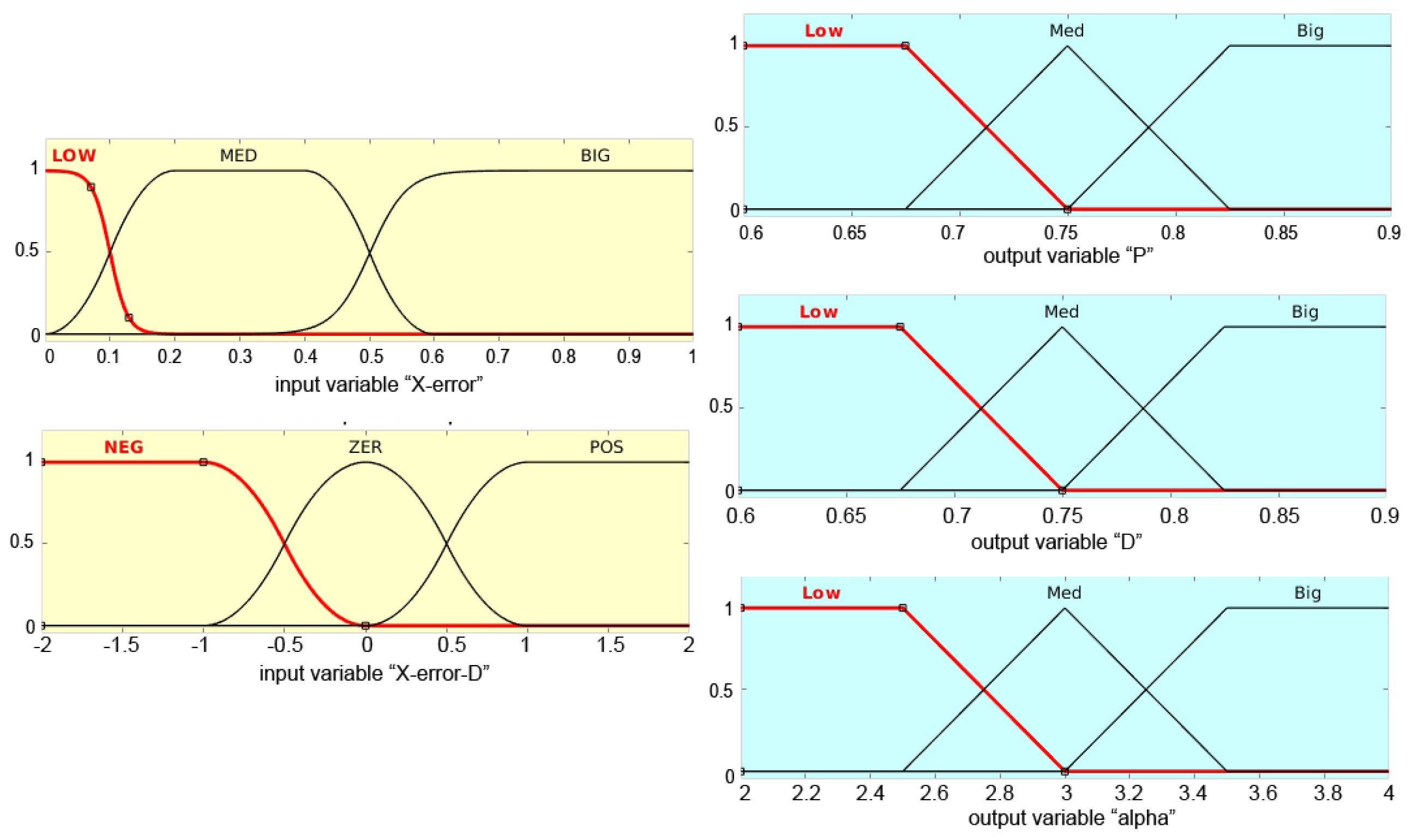
The Membership Functions types were chosen as Gaussian for the inputs and triangular for the outputs. This is the setup present in most of the literature cited by this work when it comes to PID gains tuning with fuzzy logic. The existing works were followed as a start point regarding the rules, and the rules were defined according to the UAV’s desired behavior. For instance, if the position error X-error and its time derivative X-error-D are sufficiently small in the present approach, there is no need for large PID gain values. Since no "crisp functions" were used, final gains regularly tend to be slightly different from those in the center of the membership function. The fuzzy inference technique adopted in this work is based on the classical Mamdani [42] inference method and on the centroid defuzzification method.
The fuzzy rule Table 1 can be seen as the following. The symbol ‘B’ represents ‘Big’, ‘M’ for ‘Medium’, and ‘L’ for ‘Low.’ The outputs should be interpreted as K P , K D , and Alpha gains. Hence, the output notation ’LMB’ should mean that the proportional ( K P ) gain is Low, the derivative ( K D ) gain is Medium, and Alpha gain is Big. For the integrative ( K I ) gain, the formula below is used [43]. As the desired behavior of the controller is the same for when the position error is positive or negative, the absolute value of the error was used. Regarding the derivative, it was the derivative of the absolute value of the error.
K I = K P 2 / ( α K D )

Selecting the Range of PID Gains for Horizontal Motion Control

The methodology to define the range of each of the PID gains for the horizontal motion control (x and y axis) followed [44], and [43] with a modification proposed by this work.
First, the ultimate gain ( K u ) and the oscillation period ( T u ) [45] are obtained. This is done by removing the derivative and integral parts of the PID and increasing the proportional gain until the point that the output of the control loop has stable and consistent oscillations. In this work, the measured ultimate gain was of 2.2 and the oscillation period of 4 s.
With the measured values of K u and T u , the Zhao/Larson gains K P , m i n , K P , m a x , K D , m i n and K D , m a x were calculated:
K P , m i n = 0.32 K u , K P , m a x = 0.6 K u ,
K D , m i n = 0.08 K u P u , K D , m a x = 0.15 K u P u .
Provided that the traditional Ziegler-Nichols exhibits a high overshoot and that the overshoot is reduced but not removed by the above described method, this work proposes the following modification. The modification is to use a compression factor to reduce the fuzzy range of the PID gains, which will smooth the control signal and make it more suitable for UAV applications, where a fast convergence is desired but without a very high overshoot.
Therefore, the actual adopted gains K P , m i n , K P , m a x , K D , m i n and K D , m a x are obtained as follows:
K P , m i n = K P , m i n K P , m i n 7 , K P , m a x = K P , m i n + K P , m a x 7 ,
K D , m i n = K D , m i n K D , m a x 7 , K D , m a x = K D , m i n + K D , m a x 7 .
Finally, the summary of the limits can be seen in Figure 5, where the left shows the two inputs and the right shows the three outputs.

3. Results

3.1. Horizontal Motion Control Tests in the Simulation Environment

The proposed solution was tested in a simulation environment and compared with other solutions. The other solutions adopted for comparisons are:
  • ArduPilot built-in GUIDED mode controller.
  • Cascaded-PID solution tuned by the Ziegler-Nichols method.
  • Cascaded-PID solution tuned by the methods in [44], which were detailed in [43].
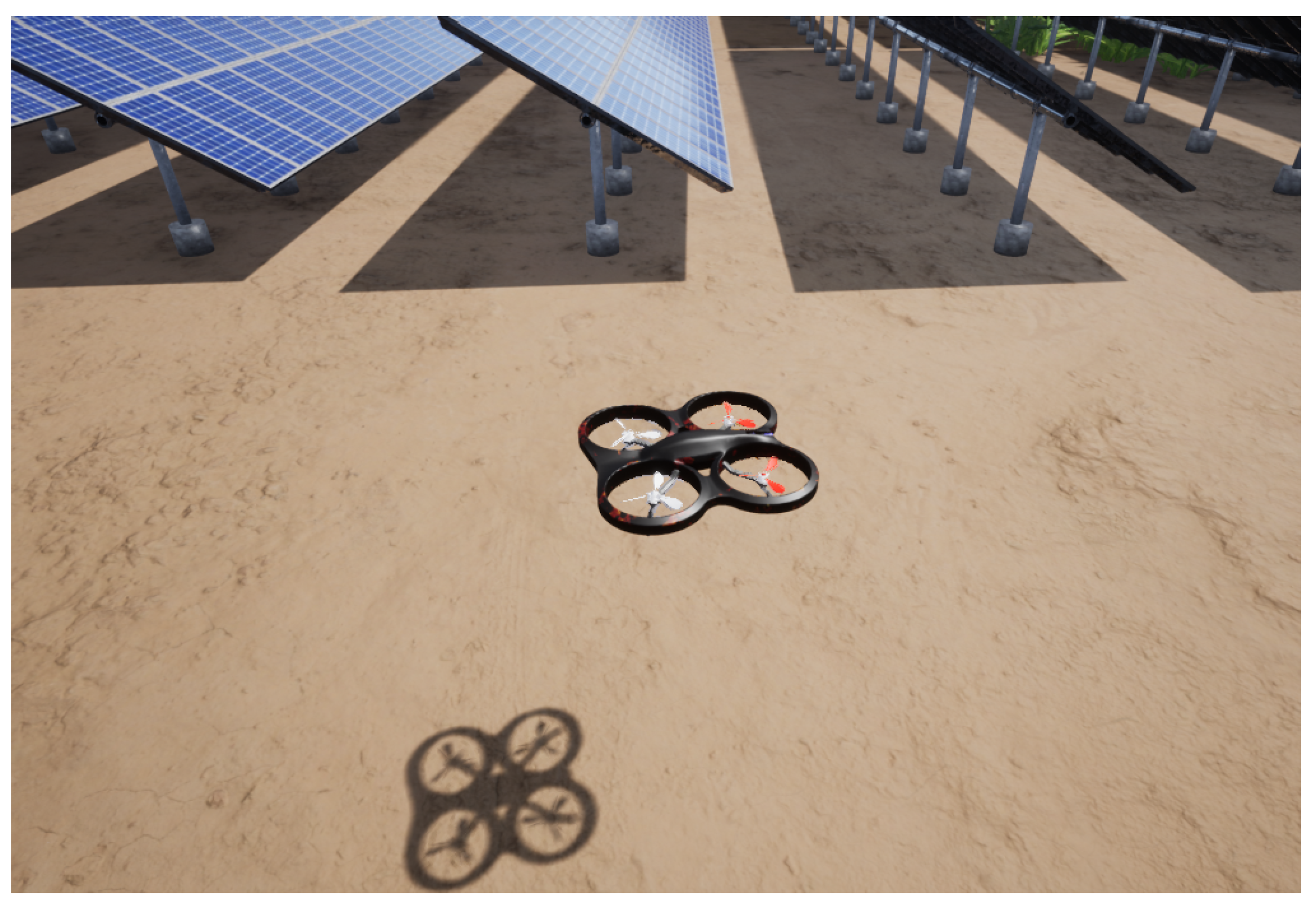
The tests were performed in a simulation environment (Figure 6) that runs in Windows operating system with Windows Subsystem for Linux (WSL) Ubuntu 18.04.5 LTS 64 bits. The computer has an Intel i9-9900K 3600 MHz processor with an NVIDIA GeForce RTX 2080Ti graphics card and 48 GB RAM.
The software Unreal Engine 4 (UE4) with the AirSim plugin [46] was used for the simulations trials. AirSim was developed by Microsoft, and is an abbreviation for Aerial Informatics and Robotics Simulation. This plugin program provided some important resources for this work, especially with regard to input/output signals, corresponding to the behavior of sensors and actuators, sent to and received from the UAV flight controllers. In the tests, the UAV was commanded to go from position 2 m at East from takeoff position to −2 m. Therefore, a total movement of 4 m was performed. The command to move was sent around 1.6 s after starting recording the logs and building the graphs.

Simulation Results

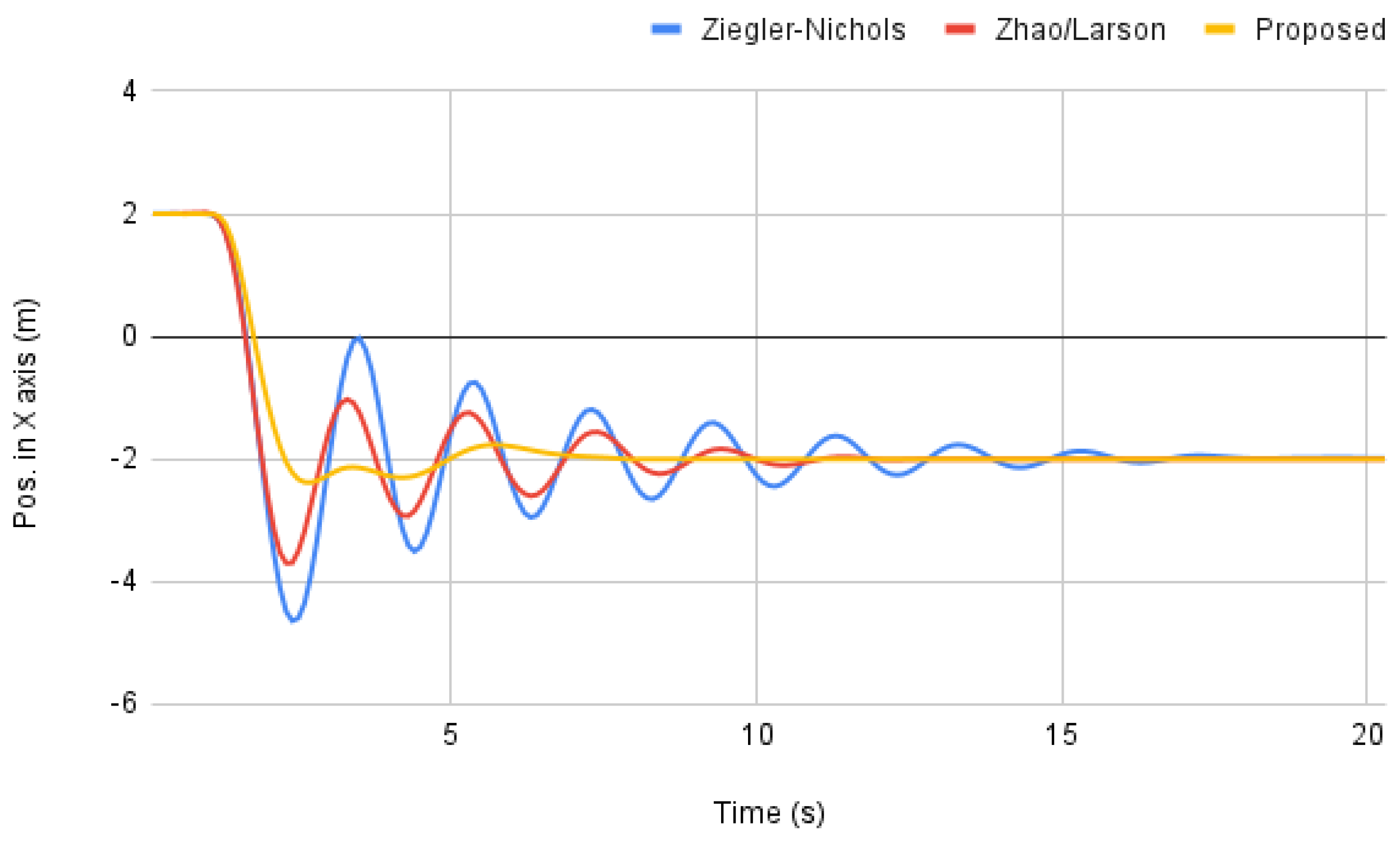
First, the three tuning methods for the Cascaded-PID were evaluated (Figure 7). It is possible to notice that, as already shown in [43,44], the Zhao/Larson method achieves the same convergence time as the Ziegler-Nichols but with lower overshoot and faster accommodation profile. In UAV applications, fast convergence is desirable, but the accommodation property is more important, as the UAV usually needs to acquire data with onboard sensors. Therefore, the solution proposed in this work is better suited for UAVs as it can achieve accommodation in a faster way with significantly less overshoot. By considering an acceptable error of 1 cm, the proposed solution reaches accommodation in 6.7 s, against 10.8 s achieved by using the Zhao/Larson tuning approach and more than 20 s achieved with the Ziegler-Nichols tuning method.
The proposed method was also compared with ArduPilot’s built-in controller in GUIDED mode, in which ArduPilot accepts target position commands and updates the velocity control at a rate of 50 Hz. A ROS message of the target position was sent using MAVROS. The result is presented in Figure 8. From the curve, it is possible to conclude that the ArduPilot achieves a shorter time of accommodation. However, the proposed method performed very well to reach the desired position, being 1.5 s faster than the ArduPilot, with a small overshoot of less than 0.5 m (Figure 9).
It is important to note that the ArduPilot controller is very advanced and has been developed for many years, counting with a big team of developers and contributors.
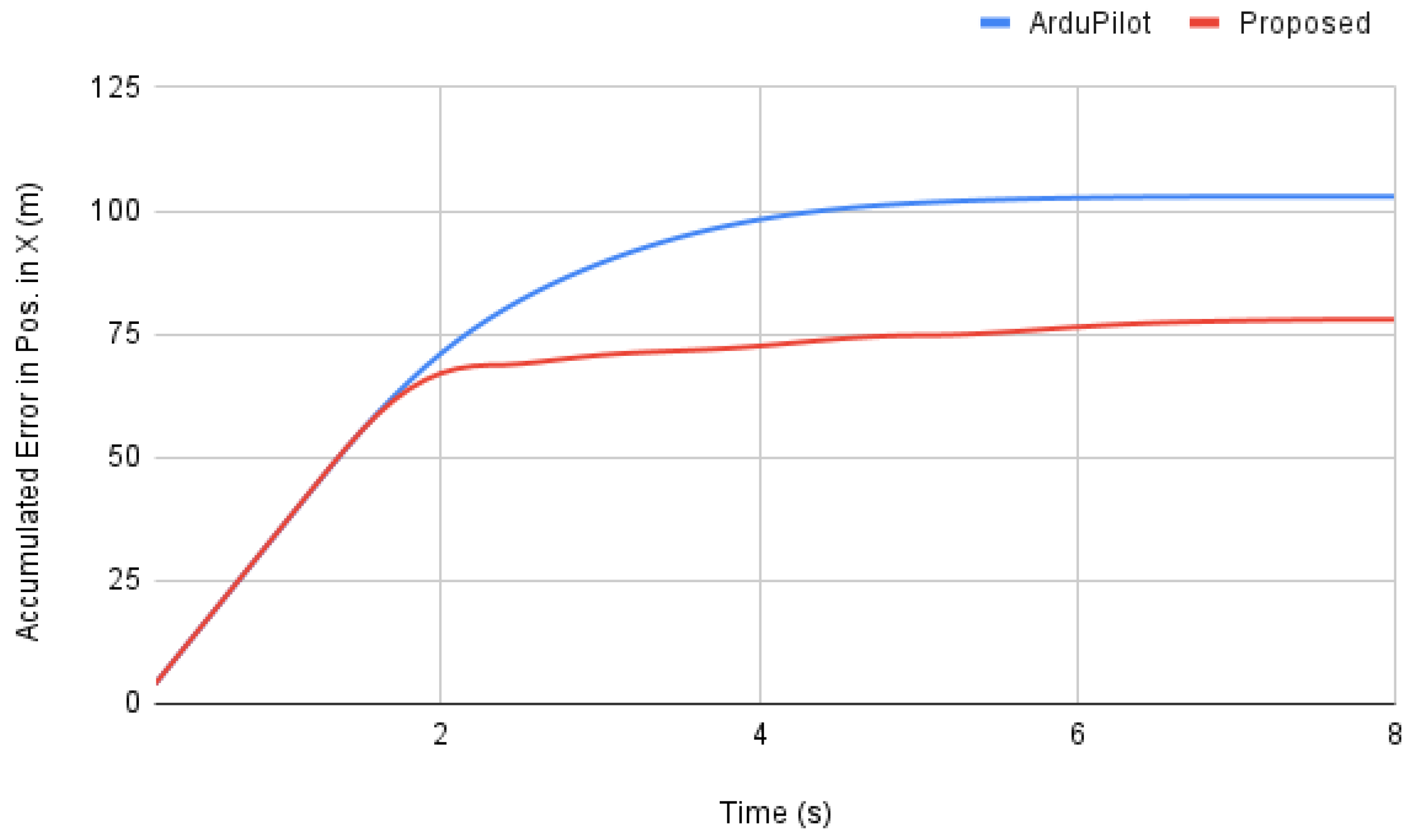
Furthermore, in comparison with ArduPilot’s results, in Figure 10 the accumulated error can be analyzed. The accumulated error is a measure that shows how much the UAV was away from the desired position over time. The upper line shows the ArduPilot’s accumulated error in terms of position in X axis, while the lower line represents the results of this proposed method. Both have crescent errors before two seconds, but it is shown that the ArduPilot stabilizes this error almost in 6 s, while the proposed method takes more than that to be a fairly horizontal line. However, the most meaningful information in this comparison is that the difference between both methods at the end of the experimentation is almost 25 m. This means that counting on every small error that both had on the trajectory tests, the proposed method shows itself significantly more accurate in terms of position in x.
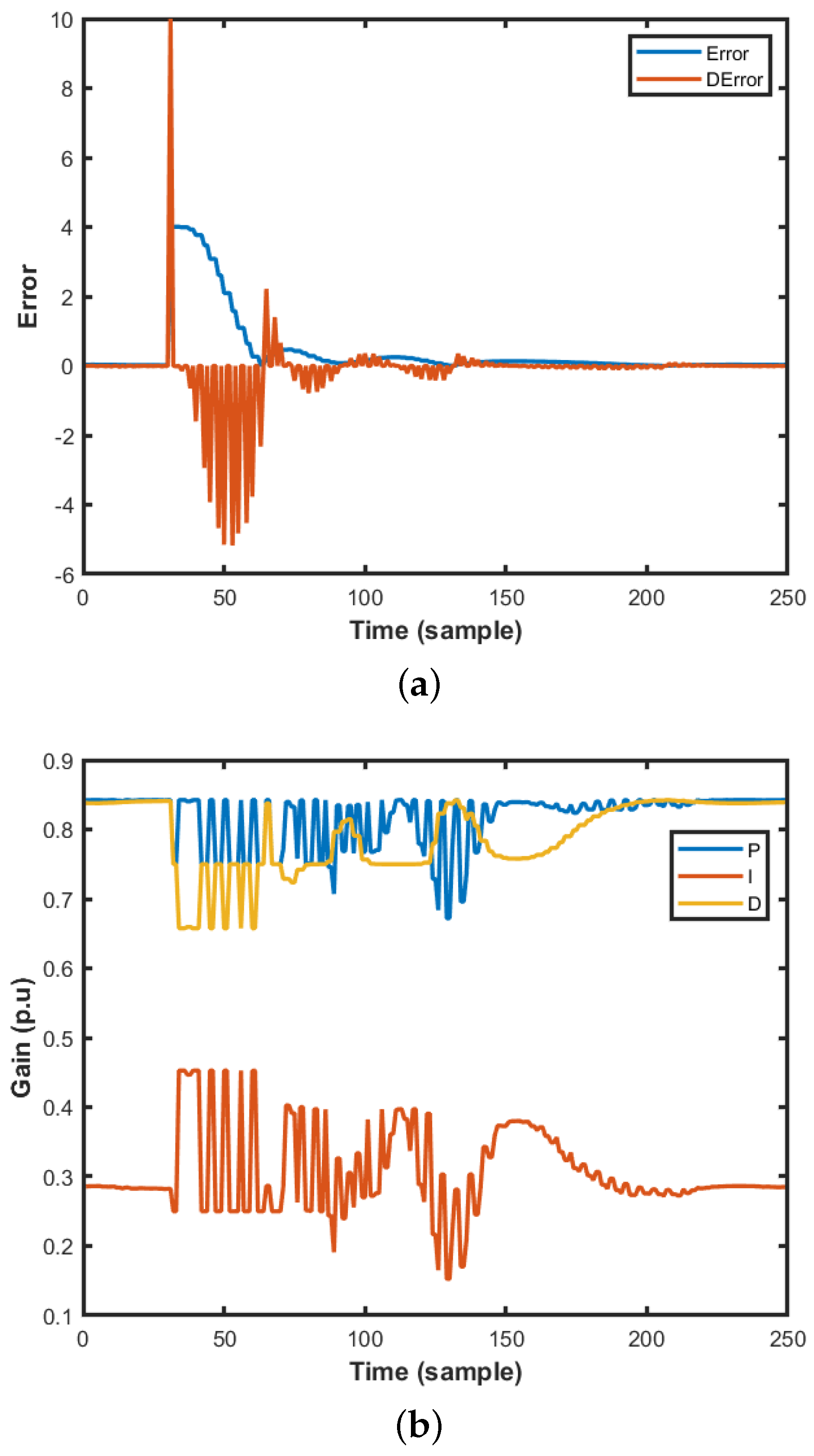
Regarding the Fuzzy Logic PID gains used in the proposed method, they can be observed in Figure 11, by the side of a graph with the calculated error and error time derivative. The peak of the derivative error, in the beginning, is due to discontinuity generated by variable initialization and should not be considered. As explained in the previous section, the error curve is shown in absolute value.
The behavior of the PID gains variations shows that the Fuzzy Logic was properly configured as in the beginning when the error exhibits large values, the derivative gain has lower values but increases every time the error is approaching the setpoint. In addition, the derivative gain tends to reduce even more if the derivative of the error is negative, meaning that the UAV is progressing correctly. The integral gain tended to increase if there is an error for a long time, being smoothly reduced if the UAV is around the setpoint for some time. Regarding the proportional gain, it is possible to observe that it is basically directly following the error.
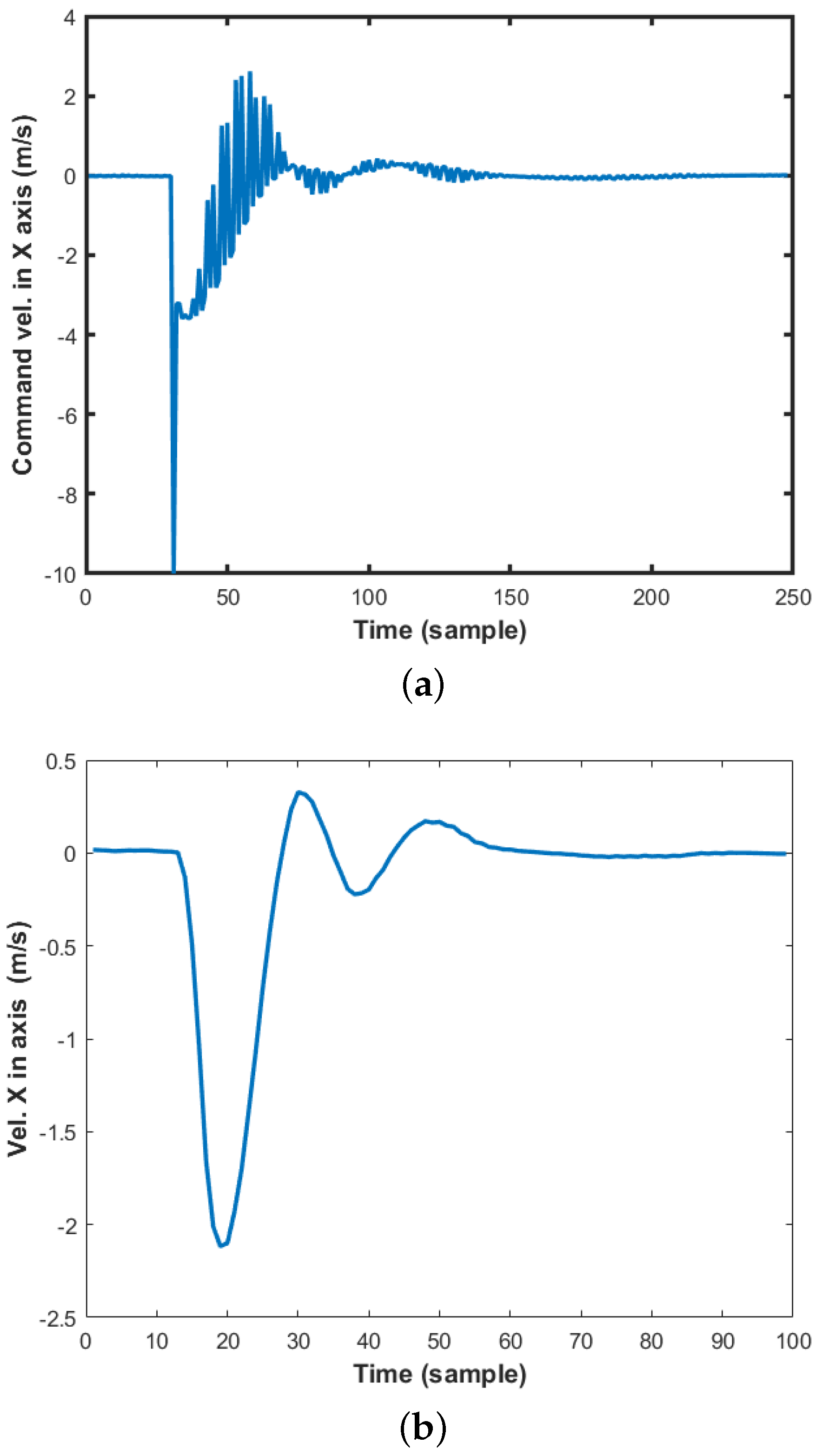
A fact that deserves to be highlighted in the graphs in Figure 11b are the oscillatory behaviors of the P, I and D gain estimates. These behaviors are probably caused by the measurement of the error derivative illustrated in Figure 12a, and are also propagated to the velocity command represented in Figure 12a. Although this type of oscillatory behavior is undesirable, it did not affect the actual measured velocity (Figure 12b). However, the issue regarding the chattering mitigation needs to be further investigated in future work.
Finally, the commanded velocity and the measured velocity can be compared in Figure 12. The sample times are different because the commands are sent at a rate 2.5 times superior than the measurements. Therefore, the graphs have the same time range in seconds.
It can be observed that the actual measured velocity of the UAV does not reach the commanded velocity. That happens because new commanded velocities are sent before the UAV can reach the previously sent one. In addition, the UAV has a limited maximum velocity, which was set to 3 m/s. Therefore, if the Fuzzy logic Cascaded-PID calculates a commanded velocity larger than 3 m/s, as it happened in the beginning as the UAV was steady and the error was big, the UAV is not able to immediately reach that velocity because of inertia.
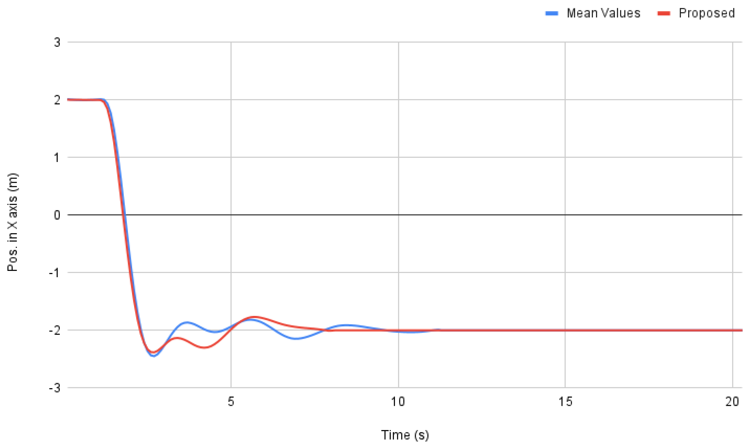
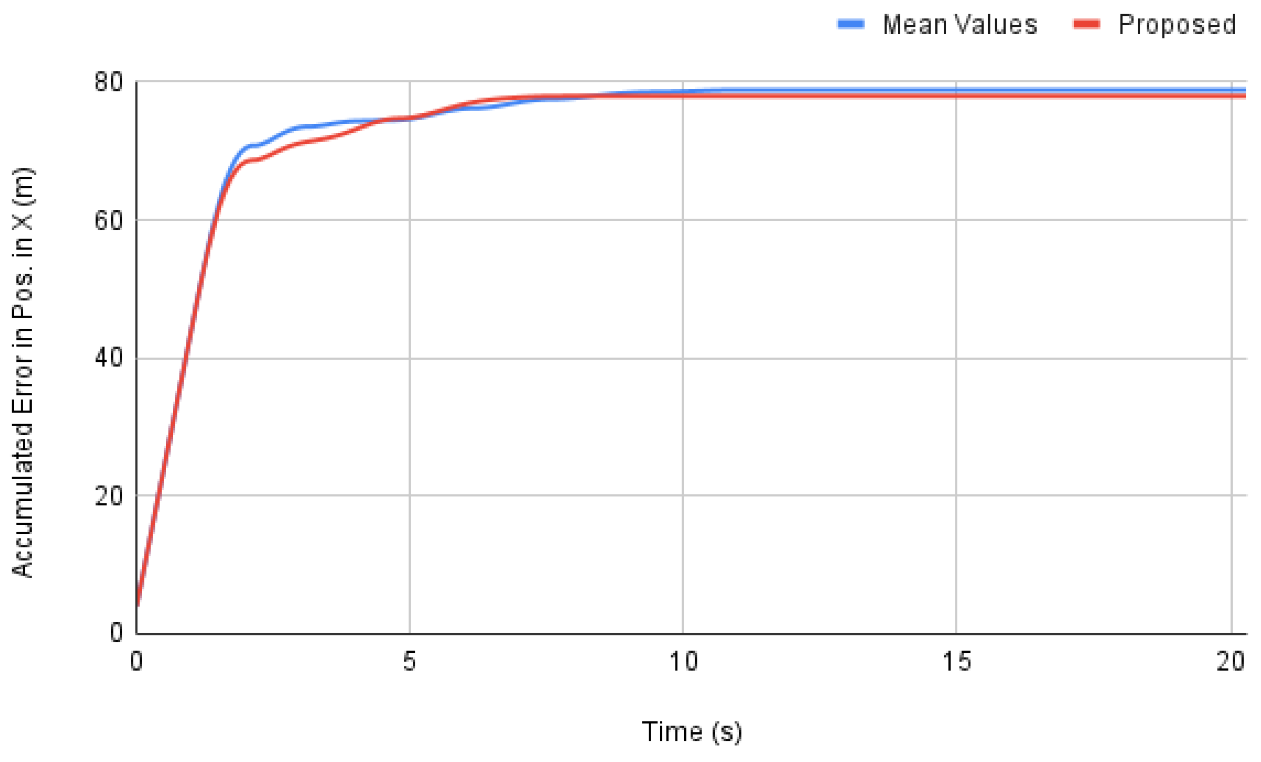
In another perspective, in Figure 13, the proposed method is compared to fixed PID gains using the mean values of the Fuzzy Logic gains. This clarifies the importance of the adaptive controller for such purposes, while the mean values of fuzzy gains present still reasonable results, the variation of the fuzzy gains shows a smaller overshoot on the first attempt to stabilize, oscillates less than the mean-gains approach, and achieve the desired position in X axis before than the mean-values method. Still compared to a the method using fuzzy gains’ mean values, the accumulated position error in X axis is slightly smaller for the proposed method at the end of the experimentation in Figure 14. The accumulated error from the proposed method is greater than the mean-values method only near 7 s, where it is trying to stabilize for the last time, with no further oscillations, while the mean-values method oscillates and thus briefly achieves the objective position.
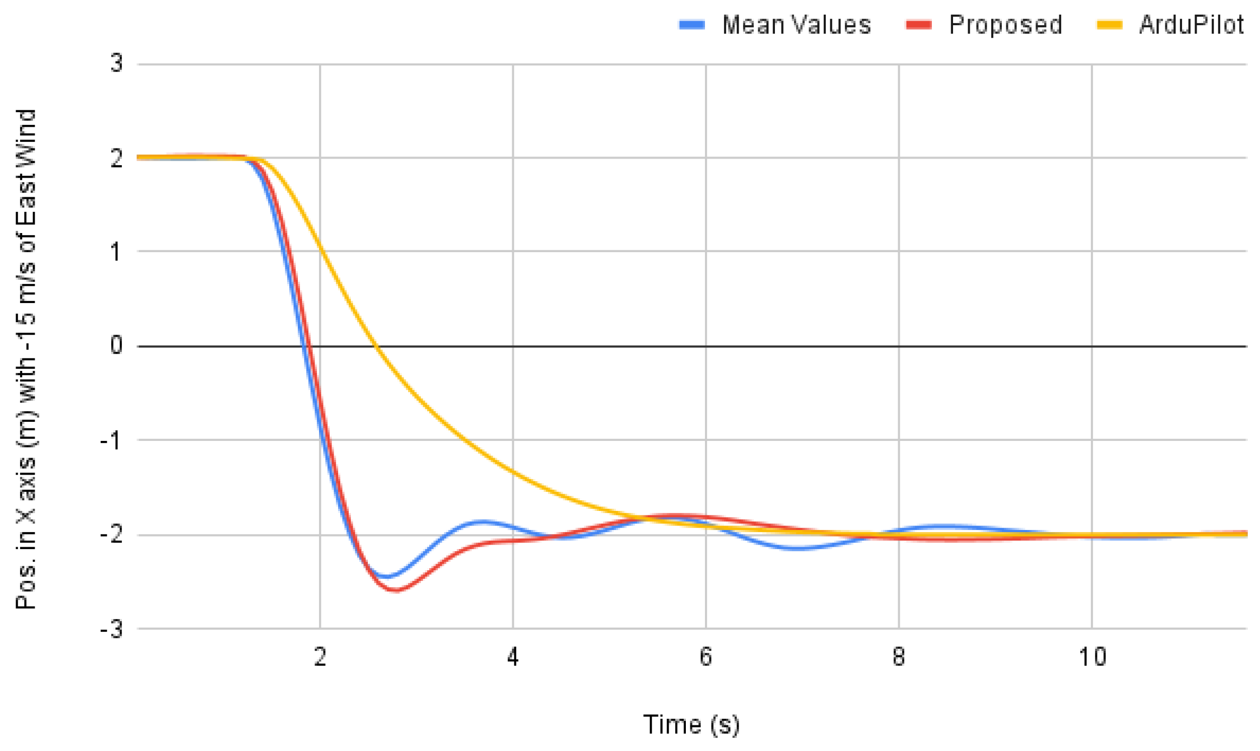
Finally, a last simulation was performed, when a wind of 15 m per second was introduced. The results can be seen in Figure 15. It is possible to observe that the proposed method has a better performance than the approach using only the mean values. In addition, it achieves nearly the same time of accommodation than the Ardupilot solution, with faster convergence.

3.2. Altitude Control Tests in Real Flight

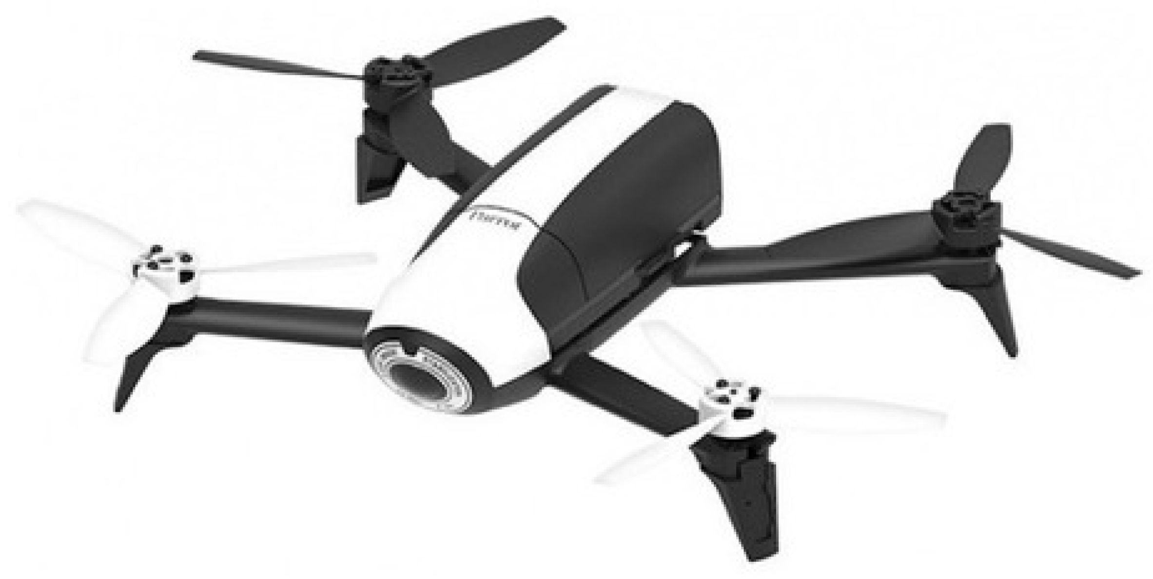
In the real implementation, the multirotor Parot bebop 2 was used. This UAV is shown in Figure 16. Its system provides a compatible network interface for ROS, by furnishing the required sensor information as well as the control interface. Any other compatible UAV can also be used, replacing only the proper interfaces.
Only height control is used in the test, while the original FMU algorithm still handles stabilization and position control. This ensures safety once the UAV is stable and locked into position. Figure 17 shows the UAV flight on a blue screen room during the test.
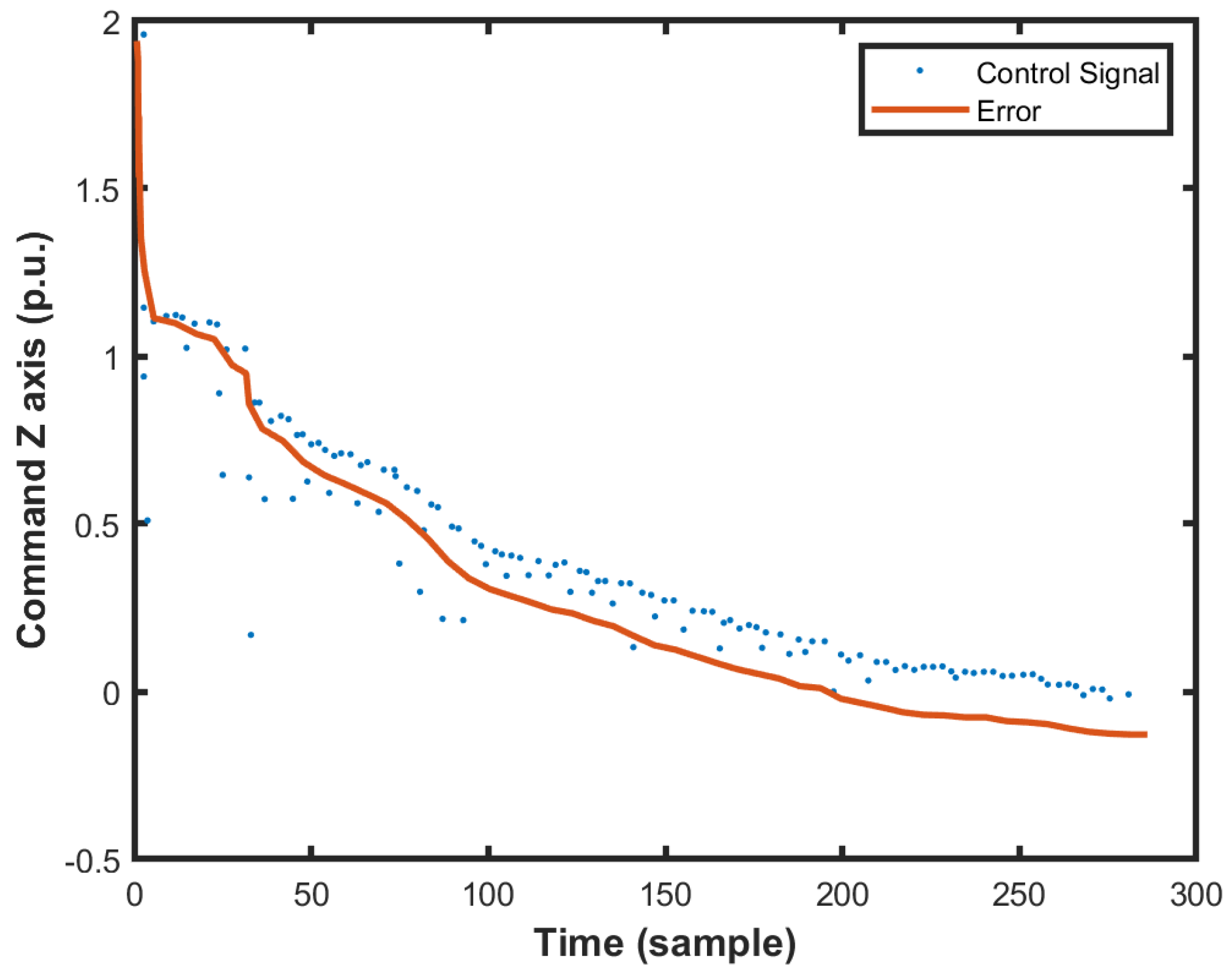
In order to avoid discontinuous movements, the method was tested using ramp profiles from one altitude setpoint to the next one. Figure 18 shows the control signal and the error measurements. The dotted line represents the overall behavior of the control signal that is applied in discrete time instants. Note that the error has a well-behaved time profile. The slightly oscillatory behavior is due to the effects of environmental conditions.
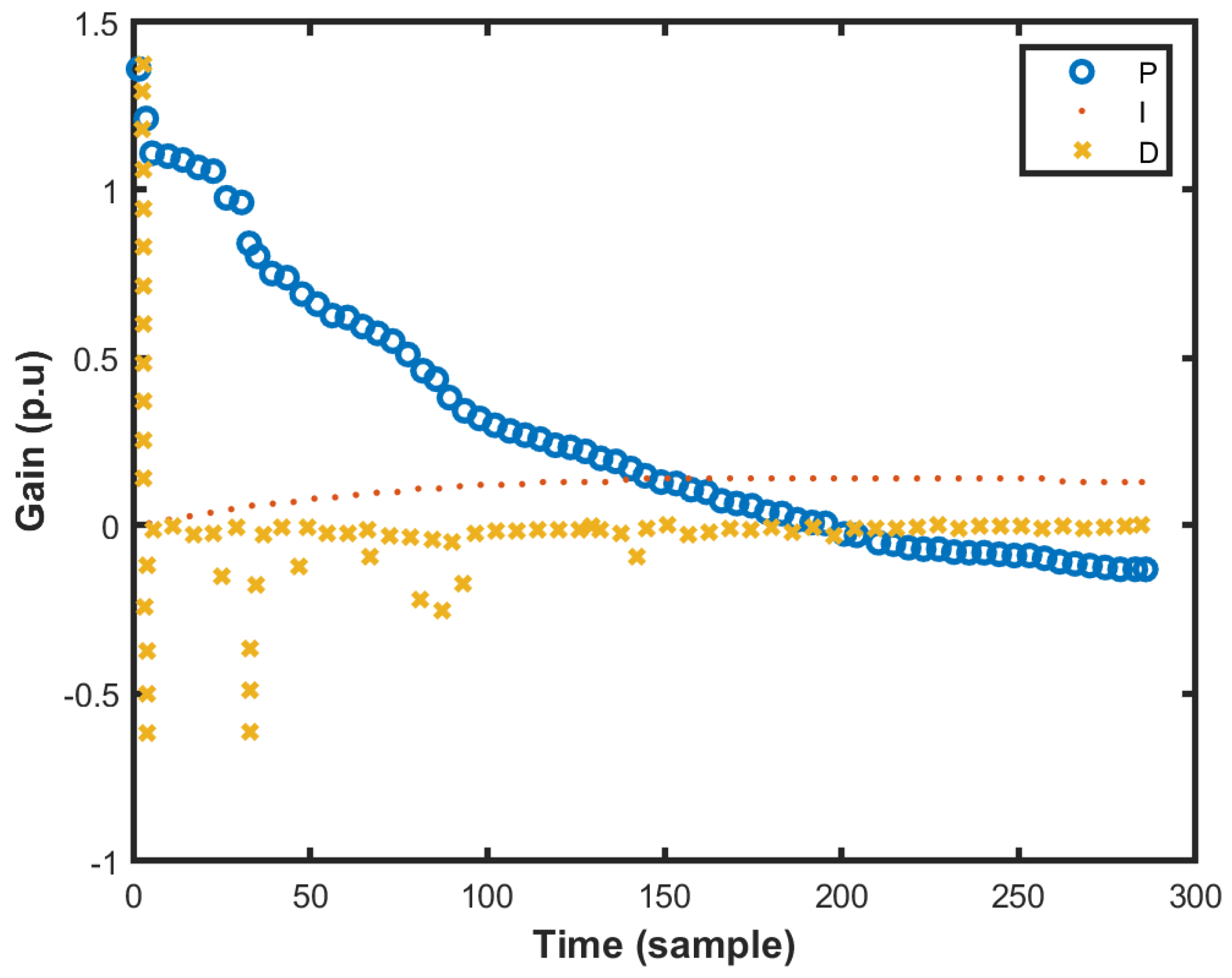
The control PID gains estimated by the proposed fuzzy algorithm are shown in Figure 19. Their performances are within the expected patterns. It is also noticeable that the derivative estimation changes were more aggressive than the other two.

4. Discussion

In the literature, most of the Fuzzy Logic tuning solutions have rules defining the PID gains ( K P , K D , and K I ) based on the output error and its time derivative. In this work, however, the absolute value of the output error is used to generate the Fuzzy rules. With this strategy, the deviation between the desired and current UAV position always assumes positive or null values, which facilitates the definition of “low”, “medium” and “high” levels for the fuzzy algorithm. In the literature, it is common to find the same definitions of such levels for both the positive and negative excursions of the error time derivative, which is the same strategy adopted in fuzzy rules proposed in this work. Based on the observations made on the results obtained, we emphasize that the definition of different rules for the negative and positive excursions of the error derivative seems to influence the performance of the closed-loop and that, therefore, it should be an issue to be investigated in a future work.
In addition, one of the main challenges when using Fuzzy Logic for PID online tuning is to define a proper range of K P , K D , and K I values. This work presents a method for defining a proper range for the horizontal motion PID gains specifically applied to UAVs based on the existing literature and with a novel modification that smooths the behavior. Regarding the altitude controller, the range of PID gains was chosen empirically. Similar tuning methods could have been used for this purpose, such as the Ziegler-Nichols ultimate gain and oscillation period method, or some variant tuning scheme as fast as the Zhao/Larson method, but with better settling time.
Regarding the results, some oscillations were verified on the commanded PID gains, which may be due to different rates among the different systems (ROS, FMU, MATLAB/Simulink). This affected the commanded velocity but did not affect the actual measured velocity. The MATLAB/Simulink was used for this solution’s proof of concept version, and the Fuzzy Logic algorithm should be embedded in the ROS Python or C++ scripts in future work. By doing so, we expect to achieve a faster and more synchronized system.
In terms of evaluation, this research work opens up several future possibilities. For instance, it is expected the deployment of this method in a real UAV inspection mission. Besides, the authors intend to insert the proposed control algorithm along with an optical flow algorithm for performing autonomous flight.

5. Conclusions

Nowadays, UAVs have been widely applied in diverse applications because of their flexibility of maneuvers, reducing risks to human life, ease to control, and cost-effectiveness. A drawback is the necessity of a platform with a high degree of stability to prevent the UAVs from falling and maintaining the desired orientation and path during the flight. Many solutions rely on PID controllers. However, its design and adjustment can be difficult. Therefore, this work proposed a novel approach composed of a Cascaded-PID Fuzzy Logic controller, where the system have adaptive capabilities engendered by the Fuzzy Logic part.
In this specific scenario, the fuzzy rules along with the membership functions play a crucial role in defining whether PID gains should prioritize stability. For instance, enhancing derivative gain in a constant position (zero error) scenario or prioritizing high gain PI for faster response when position error and its time derivative are both large.
Simulations and flight tests were conducted to demonstrate the effectiveness of the proposed method. As it can be seen from the results and discussions, when compared to the traditional Ziegler-Nichols method and another fuzzy method from the literature, the proposed solution provides much faster accommodation and smaller error amplitudes. Regarding the comparison with the built-in controller present in the ArduPilot flight control unit, the proposed solution achieves faster convergence and smaller accumulated error.

Author Contributions

Conceptualization, F.A.A.A. and M.F.P.; methodology, F.A.A.A. and I.P.G.; software, F.A.A.A., I.P.G. and G.F.C.; validation, M.F.P. and A.R.L.Z.; formal analysis, A.R.L.Z., L.F.A. and D.B.H.; investigation, F.A.A.A., M.F.P. and A.R.L.Z.; writing—original draft preparation, F.A.A.A., I.P.G., A.G.d.M. and G.F.C.; writing—review and editing, L.F.A., M.F.P., A.R.L.Z. and D.B.H.; visualization, F.A.A.A., A.G.d.M. and M.F.P.; supervision, F.A.A.A., M.F.P. and D.B.H.; project administration, F.A.A.A. and M.F.P.; funding acquisition, M.F.P., A.R.L.Z. and D.B.H. All authors have read and agreed with the submission of the current manuscript version.

Funding

The authors also would like to thank their home Institute CEFET/RJ, the federal Brazilian research agencies CAPES (code 001) and CNPq, and the Rio de Janeiro research agency FAPERJ, for supporting this work.

Institutional Review Board Statement

Not applicable.

Informed Consent Statement

Not applicable.

Data Availability Statement

The source-codes are openly available in https://github.com/piradata/wpg, accessed on 23 December 2021.

Conflicts of Interest

The authors declare no conflict of interest.

Abbreviations

The following abbreviations are used in this manuscript:
UAVUnmanned Aerial Vehicle
ROSRobot Operating System
GPSGlobal Positioning System
IMUInertial Measurement Unit
PIDProportional-Integral-Derivative
FMUFlight Management Unit

References

  1. Biundini, I.Z.; Pinto, M.F.; Melo, A.G.; Marcato, A.L.; Honório, L.M.; Aguiar, M.J. A Framework for Coverage Path Planning Optimization Based on Point Cloud for Structural Inspection. Sensors 2021, 21, 570. [Google Scholar] [CrossRef]
  2. Pinto, M.F.; Honorio, L.M.; Melo, A.; Marcato, A.L. A Robotic Cognitive Architecture for Slope and Dam Inspections. Sensors 2020, 20, 4579. [Google Scholar] [CrossRef] [PubMed]
  3. Kong, W.; Zhou, D.; Yang, Z.; Zhao, Y.; Zhang, K. UAV Autonomous Aerial Combat Maneuver Strategy Generation with Observation Error Based on State-Adversarial Deep Deterministic Policy Gradient and Inverse Reinforcement Learning. Electronics 2020, 9, 1121. [Google Scholar] [CrossRef]
  4. Pinto, M.F.; Honório, L.M.; Marcato, A.L.; Dantas, M.A.; Melo, A.G.; Capretz, M.; Urdiales, C. ARCog: An Aerial Robotics Cognitive Architecture. Robotica 2021, 39, 483–502. [Google Scholar] [CrossRef]
  5. Cabral, K.M.; dos Santos, S.R.B.; Givigi, S.N.; Nascimento, C.L. Design of model predictive control via learning automata for a single UAV load transportation. In Proceedings of the 2017 Annual IEEE International Systems Conference (SysCon), Montreal, QC, Canada, 24–27 April 2017; IEEE: Piscataway, NJ, USA, 2017; pp. 1–7. [Google Scholar]
  6. Melo, A.G.; Pinto, M.F.; Marcato, A.L.; Honório, L.M.; Coelho, F.O. Dynamic Optimization and Heuristics Based Online Coverage Path Planning in 3D Environment for UAVs. Sensors 2021, 21, 1108. [Google Scholar] [CrossRef]
  7. Fernández-Caramés, T.M.; Blanco-Novoa, O.; Froiz-Míguez, I.; Fraga-Lamas, P. Towards an autonomous industry 4.0 warehouse: A UAV and blockchain-based system for inventory and traceability applications in big data-driven supply chain management. Sensors 2019, 19, 2394. [Google Scholar] [CrossRef] [Green Version]
  8. Pinto, M.F.; Melo, A.G.; Marcato, A.L.; Urdiales, C. Case-based reasoning approach applied to surveillance system using an autonomous unmanned aerial vehicle. In Proceedings of the 2017 IEEE 26th International Symposium on Industrial Electronics (ISIE), Edinburgh, UK, 19–21 June 2017; IEEE: Piscataway, NJ, USA, 2017; pp. 1324–1329. [Google Scholar]
  9. Li, X.; Duan, H.; Li, J.; Deng, Y.; Wang, F.Y. Biological eagle eye-based method for change detection in water scenes. Pattern Recognit. 2022, 122, 108203. [Google Scholar] [CrossRef]
  10. Cabassi, J.; Lazzaroni, M.; Giannini, L.; Mariottini, D.; Nisi, B.; Rappuoli, D.; Vaselli, O. Continuous and near real-time measurements of gaseous elemental mercury (GEM) from an Unmanned Aerial Vehicle: A new approach to investigate the 3D distribution of GEM in the lower atmosphere. Chemosphere 2022, 288, 132547. [Google Scholar] [CrossRef]
  11. Bouguettaya, A.; Zarzour, H.; Taberkit, A.M.; Kechida, A. A review on early wildfire detection from unmanned aerial vehicles using deep learning-based computer vision algorithms. Signal Process. 2022, 190, 108309. [Google Scholar] [CrossRef]
  12. Murray, C.C.; Raj, R. The multiple flying sidekicks traveling salesman problem: Parcel delivery with multiple drones. Transp. Res. Part C Emerg. Technol. 2020, 110, 368–398. [Google Scholar] [CrossRef]
  13. Madridano, Á.; Al-Kaff, A.; Martín, D. 3d trajectory planning method for UAVs swarm in building emergencies. Sensors 2020, 20, 642. [Google Scholar] [CrossRef] [Green Version]
  14. Wan, L.; Liu, R.; Sun, L.; Nie, H.; Wang, X. UAV swarm based radar signal sorting via multi-source data fusion: A deep transfer learning framework. Inf. Fusion 2022, 78, 90–101. [Google Scholar] [CrossRef]
  15. Zapico, I.; Laronne, J.B.; Sánchez Castillo, L.; Martín Duque, J.F. Improvement of Workflow for Topographic Surveys in Long Highwalls of Open Pit Mines with an Unmanned Aerial Vehicle and Structure from Motion. Remote Sens. 2021, 13, 3353. [Google Scholar] [CrossRef]
  16. An Unmanned Aerial Vehicle for Greenhouse Navigation and Video-Based Tomato Phenotypic Data Collection. In Proceedings of the 2021 ASABE Annual International Virtual Meeting, Anaheim, CA, USA, 11–14 July 2021; American Society of Agricultural and Biological Engineers: St. Joseph, MI, USA, 2021. [CrossRef]
  17. Smrcka, D.; Baca, T.; Nascimento, T.; Saska, M. Admittance Force-Based UAV-Wall Stabilization and Press Exertion for Documentation and Inspection of Historical Buildings. In Proceedings of the 2021 International Conference on Unmanned Aircraft Systems (ICUAS), Athens, Greece, 15–18 June 2021; pp. 552–559. [Google Scholar] [CrossRef]
  18. Casella, E.; Rovere, A.; Pedroncini, A.; Stark, C.P.; Casella, M.; Ferrari, M.; Firpo, M. Drones as tools for monitoring beach topography changes in the Ligurian Sea (NW Mediterranean). Geo-Mar. Lett. 2016, 36, 151–163. [Google Scholar] [CrossRef]
  19. Pinto, M.F.; Marcato, A.L.; Melo, A.G.; Honório, L.M.; Urdiales, C. A framework for analyzing fog-cloud computing cooperation applied to information processing of UAVs. Wirel. Commun. Mob. Comput. 2019, 2019, 7497924. [Google Scholar] [CrossRef] [Green Version]
  20. Addabbo, P.; Angrisano, A.; Bernardi, M.L.; Gagliarde, G.; Mennella, A.; Nisi, M.; Ullo, S.L. UAV system for photovoltaic plant inspection. IEEE Aerosp. Electron. Syst. Mag. 2018, 33, 58–67. [Google Scholar] [CrossRef]
  21. Aghaei, M.; Bellezza Quater, P.; Grimaccia, F.; Leva, S.; Mussetta, M. Unmanned aerial vehicles in photovoltaic systems monitoring applications. In Proceedings of the European Photovoltaic Solar Energy 29th Conference and Exhibition, Amsterdam, The Netherlands, 22–26 September 2014; pp. 2734–2739. [Google Scholar]
  22. Joyo, M.K.; Hazry, D.; Ahmed, S.F.; Tanveer, M.H.; Warsi, F.A.; Hussain, A. Altitude and horizontal motion control of quadrotor UAV in the presence of air turbulence. In Proceedings of the 2013 IEEE Conference on Systems, Process & Control (ICSPC), Kuala Lumpur, Malaysia, 13–15 December 2013; IEEE: Piscataway, NJ, USA, 2013; pp. 16–20. [Google Scholar]
  23. Tanveer, M.H.; Hazry, D.; Ahmed, S.F.; Joyo, M.K.; Warsi, F.A.; Kamaruddin, H.; Razlan, Z.M.; Wan, K.; Shahriman, A. NMPC-PID based control structure design for avoiding uncertainties in attitude and altitude tracking control of quad-rotor (UAV). In Proceedings of the 2014 IEEE 10th International Colloquium on Signal Processing and its Applications, Kuala Lumpur, Malaysia, 7–9 March 2014; IEEE: Piscataway, NJ, USA, 2014; pp. 117–122. [Google Scholar]
  24. Wang, B.; Zhang, Y. Adaptive Sliding Mode Fault-Tolerant Control for an Unmanned Aerial Vehicle. Unmanned Syst. 2017, 5, 209–221. [Google Scholar] [CrossRef]
  25. Yuan, X.; Ren, X.; Zhu, B.; Zheng, Z.; Zuo, Z. Robust H Control for Hovering of a Quadrotor UAV with Slung Load. In Proceedings of the 2019 12th Asian Control Conference (ASCC), Kitakyushu, Japan, 9–12 June 2019; pp. 114–119. [Google Scholar]
  26. Liu, D.; Liu, H.; Lewis, F.L.; Wan, Y. Robust Fault-Tolerant Formation Control for Tail-Sitters in Aggressive Flight Mode Transitions. IEEE Trans. Ind. Inform. 2020, 16, 299–308. [Google Scholar] [CrossRef]
  27. Le Nhu Ngoc Thanh, H.; Hong, S.K. Quadcopter Robust Adaptive Second Order Sliding Mode Control Based on PID Sliding Surface. IEEE Access 2018, 6, 66850–66860. [Google Scholar] [CrossRef]
  28. Eltag, K.; Aslamx, M.S.; Ullah, R. Dynamic stability enhancement using fuzzy PID control technology for power system. Int. J. Control. Autom. Syst. 2019, 17, 234–242. [Google Scholar] [CrossRef]
  29. Hu, X.; Liu, J. Research on UAV Balance Control Based on Expert-fuzzy Adaptive PID. In Proceedings of the 2020 IEEE International Conference on Advances in Electrical Engineering and Computer Applications (AEECA), Dalian, China, 25–27 August 2020; IEEE: Piscataway, NJ, USA, 2020; pp. 787–789. [Google Scholar]
  30. Ljubičić, R.; Strelnikova, D.; Perks, M.T.; Eltner, A.; Peña Haro, S.; Pizarro, A.; Dal Sasso, S.F.; Scherling, U.; Vuono, P.; Manfreda, S. A comparison of tools and techniques for stabilising unmanned aerial system (UAS) imagery for surface flow observations. Hydrol. Earth Syst. Sci. 2021, 25, 5105–5132. [Google Scholar] [CrossRef]
  31. Megyesi, D.; Bréda, R.; Schrötter, M. Adaptive Control and Estimation of the Condition of a Small Unmanned Aircraft Using a Kalman Filter. Energies 2021, 14, 2292. [Google Scholar] [CrossRef]
  32. Solihin, M.I.; Tack, L.F.; Kean, M.L. Tuning of PID controller using particle swarm optimization (PSO). In Proceeding of the International Conference on Advanced Science, Engineering and Information Technology, Bandar Baru Bangi, Malaysia, 14–15 January 2011; Volume 1, pp. 458–461. [Google Scholar]
  33. Aly, A.A. PID parameters optimization using genetic algorithm technique for electrohydraulic servo control system. Intell. Control Autom. 2011, 2, 69. [Google Scholar] [CrossRef] [Green Version]
  34. Doitsidis, L.; Valavanis, K.P.; Tsourveloudis, N.C.; Kontitsis, M. A framework for fuzzy logic based UAV navigation and control. In Proceedings of the IEEE International Conference on Robotics and Automation, 2004 (Proceedings. ICRA’04), New Orleans, LA, USA, 26 April–1 May 2004; IEEE: Piscataway, NJ, USA, 2004; Volume 4, pp. 4041–4046. [Google Scholar]
  35. Dong, J.; He, B. Novel fuzzy PID-type iterative learning control for quadrotor UAV. Sensors 2019, 19, 24. [Google Scholar] [CrossRef] [PubMed] [Green Version]
  36. Wang, Y.; Shi, Y.; Cai, M.; Xu, W.; Yu, Q. Optimization of air–fuel ratio control of fuel-powered UAV engine using adaptive fuzzy-PID. J. Frankl. Inst. 2018, 355, 8554–8575. [Google Scholar] [CrossRef]
  37. Bucio-Gallardo, E.M.; Zavala-Yoé, R.; Ramírez-Mendoza, R.A. Mathematical Model and Intelligent Control of a Quadcopter, with Non-conventional Membership Functions. J. Energy Power Eng. 2016, 10, 634–642. [Google Scholar] [CrossRef]
  38. Demaya, B.; Palm, R.; Boverie, S.; Titli, A. Multilevel qualitative and numerical optimization of fuzzy controller. In Proceedings of the 1995 IEEE International Conference on Fuzzy Systems, Yokohama, Japan, 20–24 March 1995; IEEE: Piscataway, NJ, USA, 1995; Volume 3, pp. 1149–1154. [Google Scholar]
  39. Sun, C.; Liu, M.; Liu, C.; Feng, X.; Wu, H. An Industrial Quadrotor UAV Control Method Based on Fuzzy Adaptive Linear Active Disturbance Rejection Control. Electronics 2021, 10, 376. [Google Scholar] [CrossRef]
  40. Peng-ya, X.; Yun-jie, W.; Jing-xing, Z.; Ling, C. Longitudinal attitude control of UAV based on fuzzy PID. In Proceedings of the 2018 IEEE CSAA Guidance, Navigation and Control Conference (CGNCC), Xiamen, China, 10–12 August 2018; IEEE: Piscataway, NJ, USA, 2018; pp. 1–5. [Google Scholar]
  41. Carvalho, G.; Guedes, I.; Pinto, M.; Zachi, A.; Almeida, L.; Andrade, F.; Melo, A.G. Hybrid PID-Fuzzy controller for autonomous UAV stabilization. In Proceedings of the 2021 14th IEEE International Conference on Industry Applications (INDUSCON), São Paulo, Brazil, 15–18 August 2021; IEEE: Piscataway, NJ, USA, 2021; pp. 1296–1302. [Google Scholar]
  42. Selvachandran, G.; Quek, S.G.; Lan, L.T.H.; Giang, N.L.; Ding, W.; Abdel-Basset, M.; Albuquerque, V.H.C. A new design of Mamdani complex fuzzy inference system for multi-attribute decision making problems. IEEE Trans. Fuzzy Syst. 2019, 29, 716–730. [Google Scholar] [CrossRef]
  43. Larson, K. Fuzzy Logic Tuning of a Proportional-Integral-Derivative Controller. Ph.D. Thesis, California State Polytechnic University, Pomona, CA, USA, 2016. [Google Scholar]
  44. Zhao, Z.Y.; Tomizuka, M.; Isaka, S. Fuzzy gain scheduling of PID controllers. IEEE Trans. Syst. Man Cybern. 1993, 23, 1392–1398. [Google Scholar] [CrossRef] [Green Version]
  45. Ziegler, J.G.; Nichols, N.B. Optimum settings for automatic controllers. Trans. ASME 1942, 64, 759–765. [Google Scholar] [CrossRef]
  46. Shah, S.; Dey, D.; Lovett, C.; Kapoor, A. AirSim: High-Fidelity Visual and Physical Simulation for Autonomous Vehicles. In Field and Service Robotics; Springer: Cham, Swotzerland, 2017. [Google Scholar]
Figure 1. Scheme of fuzzy addition to the PID controller.
Machines 10 00012 g001
Figure 2. Schematic of the Simplified Cascaded-PID controller.
Machines 10 00012 g002
Figure 3. Signal flowchart and architecture.
Machines 10 00012 g003
Figure 4. Simulink model for the fuzzy controller.
Machines 10 00012 g004
Figure 5. Fuzzy membership functions.
Machines 10 00012 g005
Figure 6. Simulation Environment provided by the software Unreal Engine 4 with AirSim.
Machines 10 00012 g006
Figure 7. The comparison among Cascaded-PID tuning methods.
Machines 10 00012 g007
Figure 8. ArduPilot and Proposed method compared.
Machines 10 00012 g008
Figure 9. Absolute Error comparison between ArduPilot and the proposed method.
Machines 10 00012 g009
Figure 10. Accumulated Error comparison between ArduPilot and the proposed method.
Machines 10 00012 g010
Figure 11. (a) Measured errors; and (b) Fuzzy PID gains.
Machines 10 00012 g011
Figure 12. (a) Commanded; and (b) Measured velocities.
Machines 10 00012 g012
Figure 13. Comparison between the proposed method and using the mean values of the fuzzy logic gains.
Machines 10 00012 g013
Figure 14. Accumulated Error comparison between the proposed method and using the mean values of the fuzzy logic gains.
Machines 10 00012 g014
Figure 15. Comparison among different methods in the presence of 15 m/s wind to the West.
Machines 10 00012 g015
Figure 16. The Parrot Bebop 2.
Machines 10 00012 g016
Figure 17. The UAV height control flight test.
Machines 10 00012 g017
Figure 18. Control signal and error during the experimental trial.
Machines 10 00012 g018
Figure 19. Individual control response during the experiment.
Machines 10 00012 g019
Table 1. Fuzzy Rule table.
Error
Error D LowMediumBig
NegativeLBBMMMBLL
ZeroBBMBMLBLL
PositiveLBBMMMBLL
Publisher’s Note: MDPI stays neutral with regard to jurisdictional claims in published maps and institutional affiliations.