Article

Modeling and Dynamic Characteristics of a Novel High-Pressure and Large-Flow Water Hydraulic Proportional Valve

College of Mechanical and Vehicle Engineering, Taiyuan University of Technology, Taiyuan 030024, China
*
Author to whom correspondence should be addressed.
Machines 2022, 10(1), 37; https://doi.org/10.3390/machines10010037
Submission received: 2 December 2021 / Revised: 22 December 2021 / Accepted: 27 December 2021 / Published: 4 January 2022
(This article belongs to the Special Issue Advanced Control of Industrial Electro-Hydraulic Systems)

Abstract

:
In the field of fully mechanized coal mining equipment, the hydraulic valve used in the hydraulic support is an on/off directional valve. There are many problems caused by the valve such as large pressure shock and discontinuous flow control. Therefore, a novel two-position three-way hydraulic proportional valve suitable for high-pressure and large-flow conditions is proposed to overcome the above problems. The novel valve utilizes a two-stage structure and the displacement follow-up principle is adopted between the pilot stage and the main stage to meet proportional control. In this paper, a simulation model of the novel proportional valve was established after a simplified analysis of the structural principle. Its reliability and the feasibility of the design were verified by the test results under different working conditions. Then, the step response characteristics of the proportional valve under different strokes were predicted and analyzed. Nonlinear characteristics were presented, and the closing time was shorter than the opening time because of the influence of nonlinear flow force. Under different ramp signals, the displacement of the main inlet spool was always approximately equal to the displacement of the pilot stage. Then, the motion relationship between the pilot stage and the main stage was studied, and the influence of the structural parameters on the stability was analyzed.

1. Introduction

Compared with the traditional oil hydraulic system, water hydraulic system has many outstanding advantages such as being non-pollutive, low-cost, and non-flammable [1,2]. As the key component of water hydraulic systems, water hydraulic valve is widely used in deep sea equipment, coal mining machinery, oil exploration, steel manufacturing, and other fields [3,4,5,6]. In the fully mechanized coal mining face, the working pressure of the hydraulic valve used for the hydraulic support is 31.5 MPa, and the working flow is higher than 200 L/min (Δp < 7 MPa) [7]. However, with the development of hydraulic supports in the direction of much larger mining height and accurate posture control, higher flow rates and accurate flow control are put forward for the directional valves for the hydraulic support [8]. The on/off directional valve currently used has many problems such as high pressure shock, and discontinuous and unsmooth flow [9], therefore, a high-pressure, large-flow water hydraulic proportional valve is needed, which has the characteristics of anti-pollution, high control accuracy of flow, and low pressure shock.
In the existing research, the traditional oil hydraulic directional valve is mainly a slide structure [10,11], which adopts gap seal and is easy to leak, so it is difficult to achieve high pressure in water medium. The seat valve has good sealing performance and large flow capacity, but most of them are two-position two-way structures that cannot meet the function of the hydraulic support [12,13]. Oil hydraulic valves cannot be directly used for hydraulic supports because of the above problems, but the design method of oil hydraulic proportional valve is still worth learning.
Under high-pressure and high-flow conditions, in order to achieve high-precision control, electromechanical conversion devices are often used to drive the pilot stage to accurately control its displacement or flow. Then, the displacement or flow of the main stage is proportional to the pilot stage through different control principles. Eriksson of Linköping University in Sweden divided the control principle between the main stage and the pilot stage into mechanical feedback, electrical feedback, hydraulic feedback, and hydraulic follow-up feedback [14]. Hydraulic feedback has been extensively developed [15,16], while hydraulic follow-up feedback follows behind, but it has many advantages such as good controllability, high integration, and simple structure. Zhang et al. [17], proposed an ultra-high-pressure proportional cartridge valve based on the displacement follow-up principle. Its working pressure is 70 MPa, and the rated flow reaches 1900 L/min (Δp = 0.5 MPa), which verifies the feasibility of the displacement follow-up principle and the advantage of the large flow capacity of the seat valve.
Some scholars have also proposed different water hydraulic proportional valve structures; Han et al. [18] proposed a 2/2-way hydraulic proportional valve based on the hydraulic half-bridge circuit principle. Its pilot stage uses two 2/2-way water hydraulic proportional valves, and the main stage uses a 2/2-way cartridge valve. Its rated pressure is 25 MPa, and its rated flow is 1100 L/min (Δp = 1 MPa). Zhao et al. [19] proposed a two-position three-way hydraulic proportional valve based on the famous Valvistor valve. The pilot stage adopts a high-speed on/off valve, and the main stage adopts a seat valve structure with large flow capacity. Its rated pressure is 31.5 MPa, and the rated flow is 293 L/min (Δp = 7 MPa). The former cannot realize the directional function, and the rated flow of the latter is lower than 1000 L/min. In addition, both the former and the latter use high-speed switching valves as the pilot stage, which will cause pressure fluctuations in the control chamber of the main valve. Therefore, a complex control strategy is required to achieve precise control of the spool. In the existing research, there are various electromechanical conversion devices used to drive the pilot stage of the proportional valve [20,21,22,23,24]. The combination of a motor and screw nut with the characteristics of large force and large stroke is suitable for high pressure and large flow conditions. Therefore, it is feasible to combine this electromechanical conversion device and a seat valve structure to meet the special condition of the water hydraulic system for the hydraulic support.
Above all, the existing proportional valves cannot be directly applied to the hydraulic support. Therefore, a novel water hydraulic proportional directional valve suitable for high pressure and large flow conditions based on the principle of displacement follow-up is proposed in this paper. Then, the static and dynamic characteristics are studied through a combination of simulation and experiment, and the stability of the system affected by the structural parameters is analyzed.

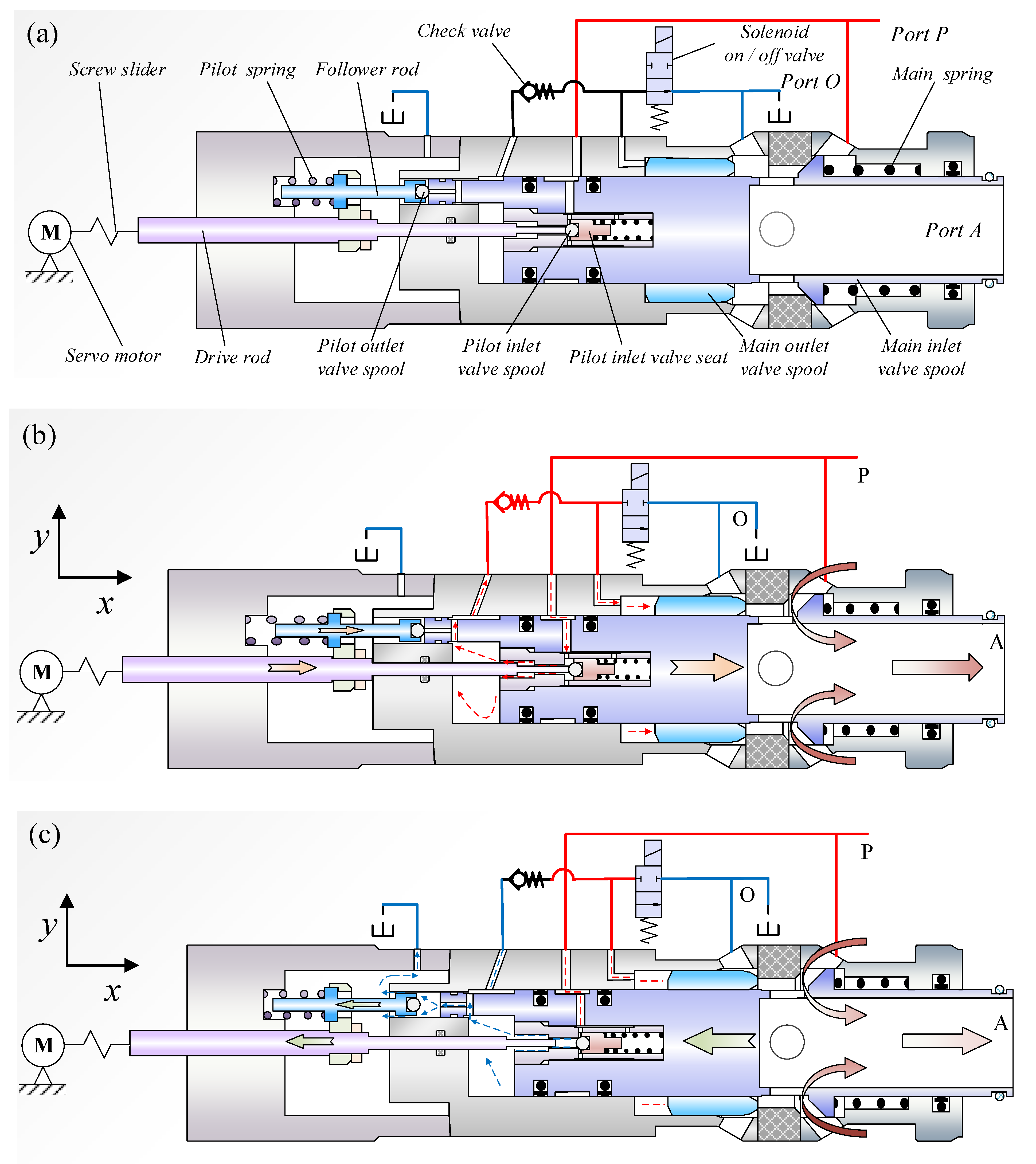
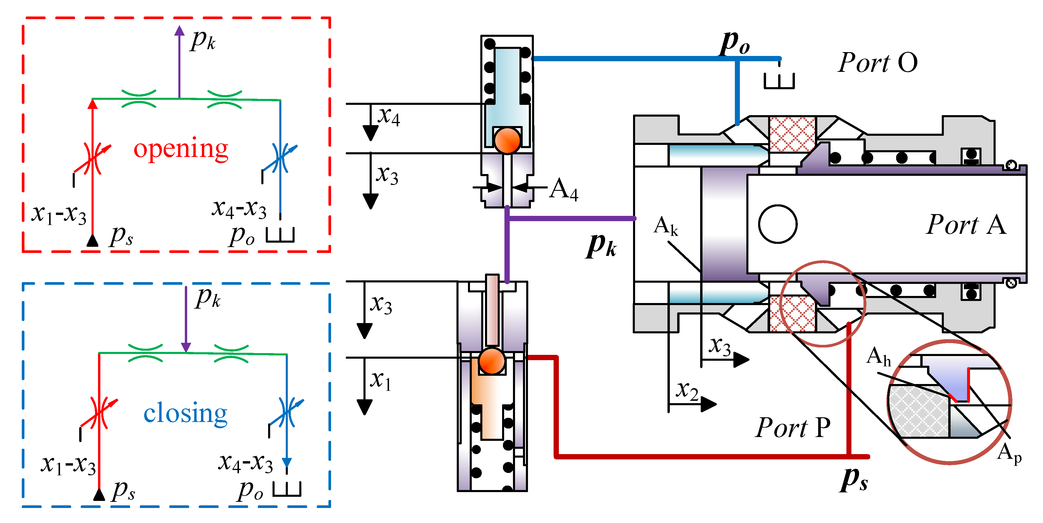
2. Structure and Working Principle

A novel two-position and three-way water hydraulic proportional valve is designed based on the principle of displacement follow-up. The electromechanical conversion device is composed of a DC servo motor and a screw slider, and the pilot stage is composed of two 2/2 valves. Its main stage adopts a seat structure with large flow capacity. On the whole, the new proportional valve is a cartridge valve with a high degree of integration.
Figure 1a shows the initial state of the water hydraulic proportional directional valve. The structure of the screw slider is ignored in the schematic diagram because its structure is not important here. The screw slider and the drive rod are connected by a thread. In the initial state, the servo motor and the solenoid on/off valve receive no input signal, and the port O is connected to the working port A.
Figure 1b shows the schematic diagram of the opening process of the proportional valve. The solenoid on/off valve is energized and closed. A positive signal is input to the motor and the screw slider, which drive the drive rod in the positive direction of the x-axis, and the drive rod pushes the pilot inlet valve spool. As a result, the high-pressure liquid from the port P enters the control chamber, through the check valve, and pushes the main outlet valve spool to move in the positive x direction until the main outlet valve port is closed. Then, the pressure of the control chamber gradually increases until it reaches the opening pressure of the main inlet valve spool, and the main inlet valve spool moves in the positive direction along the x-axis. In this process, the pilot outlet valve follows the movement of the main inlet valve spool under the force of the pilot spring and always keeps the pilot outlet valve port closed. When the moving distance of the main inlet valve spool is equal to the moving distance of the pilot inlet valve spool, the pilot inlet valve port is closed to prevent high-pressure liquid from entering the control chamber. Thus, the main inlet valve spool stops moving and maintains a balanced state. In this state, the port O is closed, and the port P is connected to the working port A, realizing the directional function. During the opening process, the displacement of the pilot inlet valve determines the opening of the main inlet valve. Therefore, in the steady state, the displacement of the main inlet valve is always approximately equal to the displacement of the pilot inlet valve.
Figure 1c shows a schematic diagram of the closing process of the proportional valve. The solenoid on/off valve is still energized and closed. A reverse signal is input to the motor and the screw slider, which pulls the drive rod to move in the negative direction of the x-axis, and the drive rod pulls the follower rod. Then, the pilot outlet valve spool moves in the negative x direction at the same time. As a result, the control chamber is connected to port O through the pilot outlet valve port, and the pressure in the control chamber decreases. Then, the main inlet valve spool moves in the negative direction along the x-axis under the pressure force. In this process, the pilot inlet valve is always kept closed under the spring force. When the displacement of the main inlet valve spool is equal to the displacement of the pilot outlet valve spool, the pilot outlet valve port is closed. The main inlet valve spool stops moving and maintains a balanced state. The opening of the main inlet valve can be reduced to zero through this process. During the closing process, the displacement of the pilot outlet valve determines the opening of the main inlet valve. Therefore, in the steady state, the displacement of the main inlet valve is always approximately equal to that of the pilot outlet valve. Because of the special mechanical structure, the displacement of the driving rod in the negative direction of the x-axis is always equal to the displacement of the follower rod in the negative direction of the x-axis. In other words, the displacement of the drive rod and the follower rod can be controlled by the electromechanical conversion device named “three-spool” position follow-up mechanism to realize two different displacement follow-up principles.
Where, x1: displacement of the pilot inlet valve; x2, displacement of the main outlet valve; x3, displacement of the main inlet valve; x4, displacement of the pilot outlet valve; ps: supply pressure; pk: pressure of the control chamber; po: outlet pressure; Ak: area of the controlling chamber, Ah; Ap: metering area.
Figure 2 shows that the proportional valve is mainly composed of three parts: the pilot inlet valve, the pilot outlet valve, and the main inlet valve. The pilot inlet valve spool and the pilot outlet valve spool are small balls; the main inlet valve spool is the seat of the pilot stage, and the opening of the pilot stage depends on the displacement difference between the main stage and the pilot stage. Therefore, the control flow chart of the proportional valve can be expressed as Figure 3.
Where, v1 is the velocity of the pilot inlet stage; qk, flow rate of the control chamber; v3, velocity of the main inlet stage; and qz, flow rate of port A.
The influence of the motor and the screw slider on the response characteristics of the proportional valve is ignored to simplify the analysis. Therefore, the control flow chart can be simplified to the relationship between the pilot valve and the main valve. It can be seen from the flow chart that there is displacement feedback between the pilot stage and the main stage.

3. Comparison between Simulation and Experiment

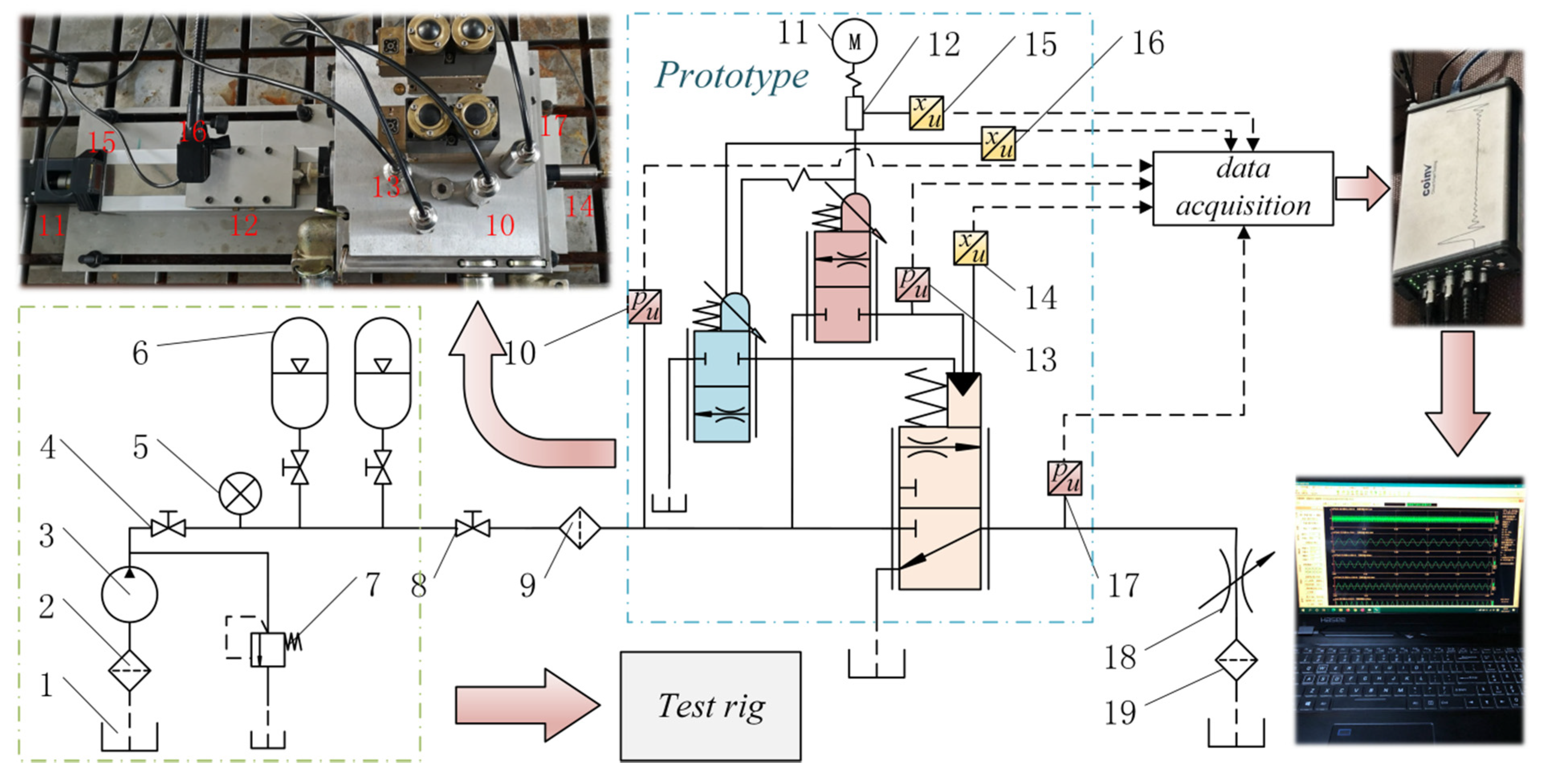
3.1. Methods and Materials

It is shown in Figure 4 that the test system is mainly composed of a water pump, accumulators, pressure gauges, pressure transducers, displacement transducers, a data acquisition collector, and so on. Ten 100 L accumulators are used to provide high pressure and large flow for the prototype. The shut-off valve 4 should be opened, and the shut-off valve 8 should be closed before the start of the test, and then the water pump is used to supply liquid to the accumulator group. The supply pressure is determined by the relief valve 7. The shut-off valve 4 should be closed, and the shut-off valve 8 should be opened at the beginning of the test. Displacement transducers 15 and 16 are used to measure the displacement of the pilot inlet valve spool and the pilot outlet valve spool. The displacement of the main inlet valve spool is measured by linear variable differential transformer (LVDT)14. Pressure transducers 10, 13, and 17 are used to measure the pressure of the supply port, the control chamber, and the working port, respectively.
1—Water tank; 2,9,19—Filter; 3—Pump; 4,8—Shut-off valve; 5—Pressure gauge; 6—Accumulator group; 7—Relief valve; 10,13,17—Pressure transducer; 11—Servo motor; 12—Screw slider; 14,15,16—Displacement transducer; 18—Throttle valve.
Figure 5 shows that the proportional valve prototype is mainly composed of a valve spool, sleeve, servo motor, screw slider, and block. The cone, sleeve, and other parts are made of stainless steel material because water is used as the medium in the proportional valve, which has good corrosion resistance and rust resistance. The main inlet valve seat is made of engineering plastics to achieve good sealing performance of the main inlet valve port, as well as impact resistance, corrosion resistance, and wear resistance. The other stainless steel material with better processing performance is used as the valve block, which also has good anti-corrosion properties.
The parameters of instruments used in the test are shown in Table 1.

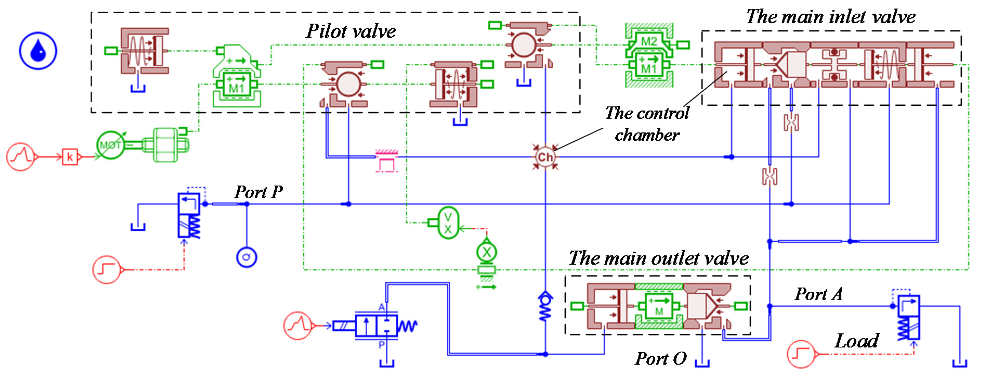
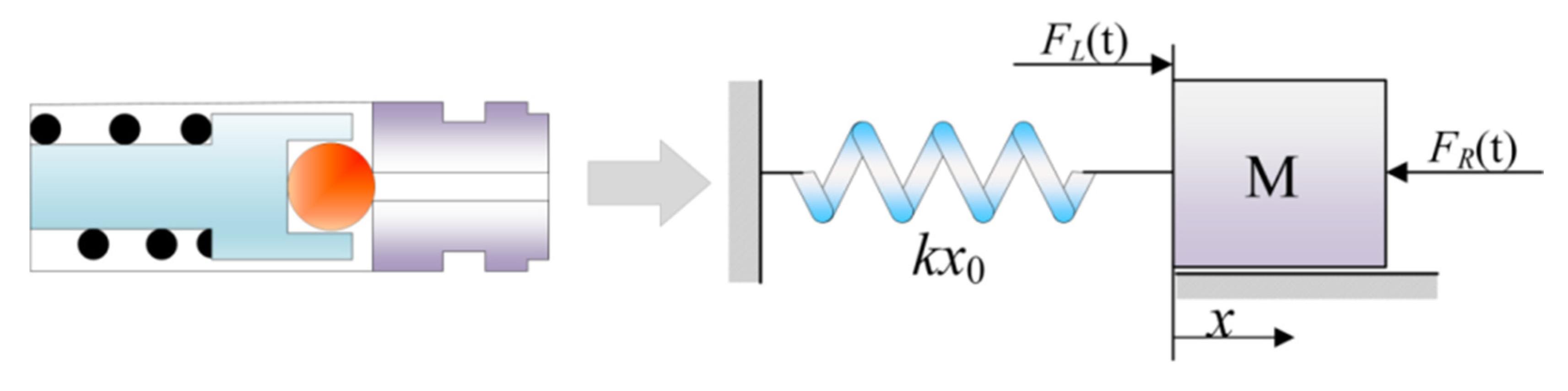
3.2. Simulation Method

Digital simulation methods based on modern control theory are suitable for nonlinear systems, which can easily include nonlinear factors and are suitable for multiple input and output variables [15]. The simulation model of the proportional valve can be easily built by the commercial software LMS AMESim compared with other software [19].
The following simplifications were made when the simulation model in Figure 6 was built:
  • The influence of the pipeline is ignored.
  • The friction generated by sealing rings of pilot valves is ignored.
  • The flow force of the pilot valve port is ignored.
Water is used as the working medium. when there is no load, the load relief valve is set to be zero. The influence of the electromechanical conversion device on the system characteristics is ignored, and the displacement of the pilot stage is used as the input signal of the proportional valve to simplify the analysis.

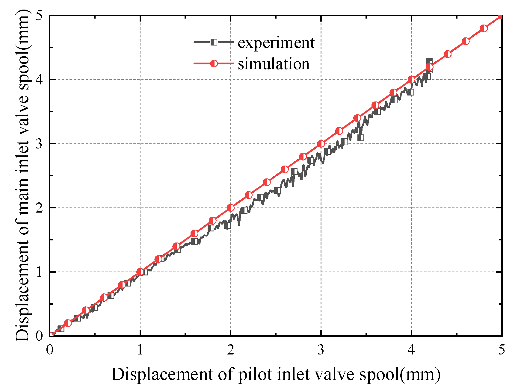
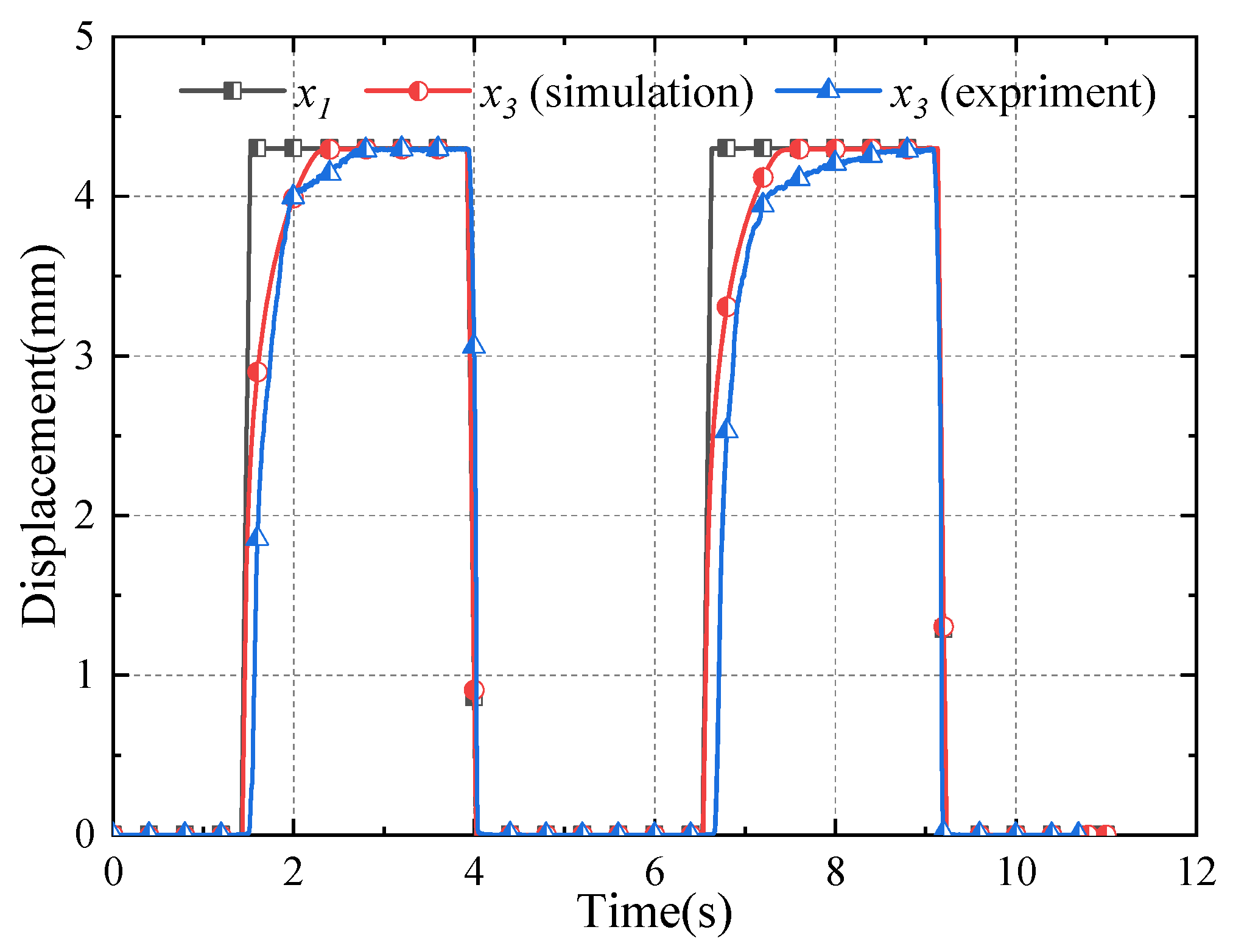
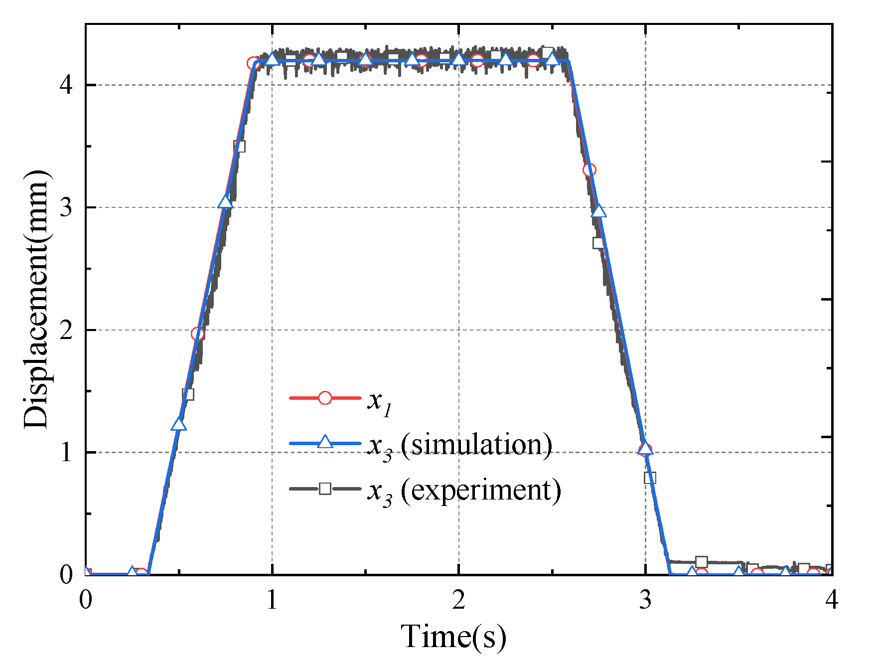
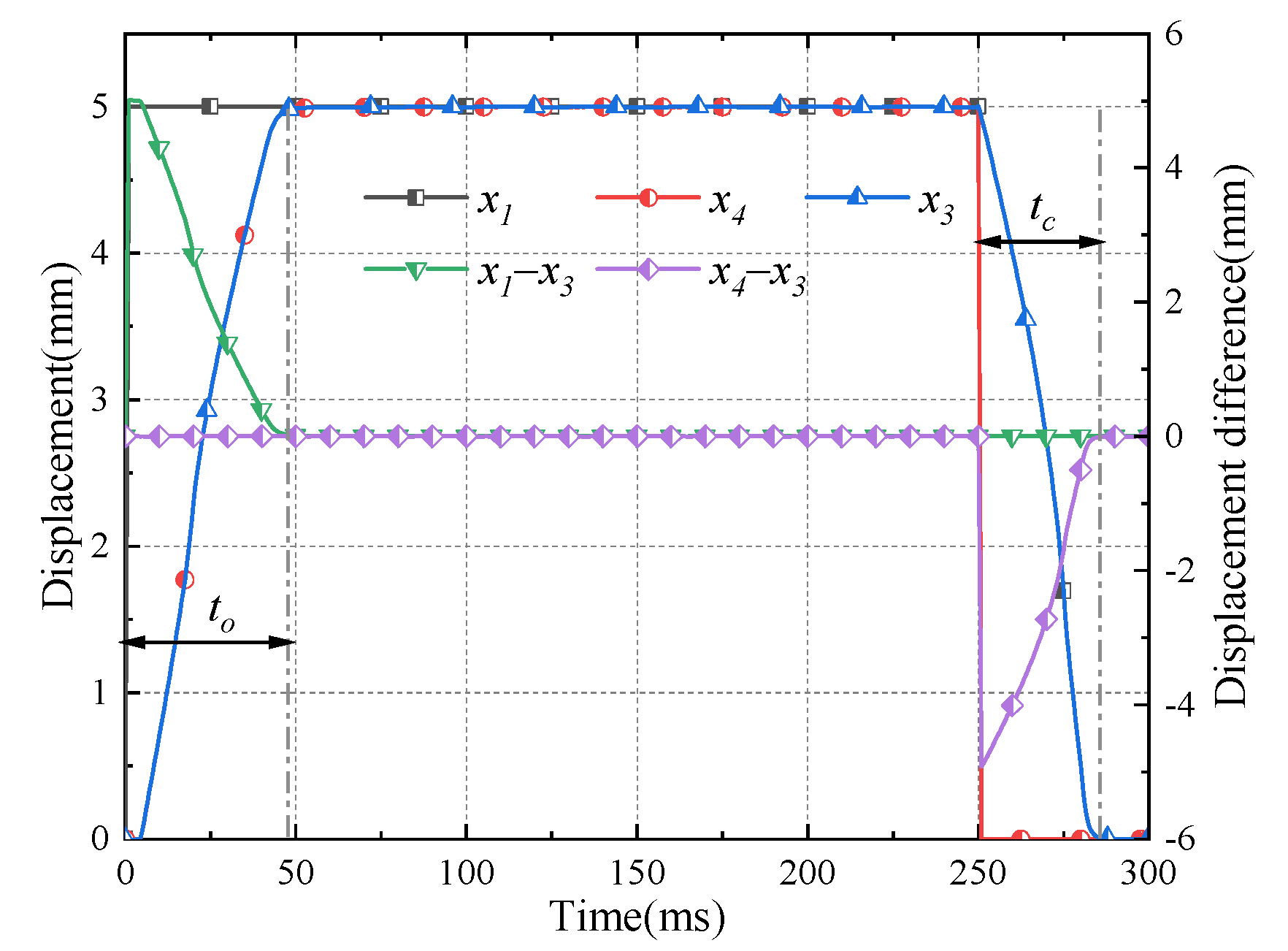
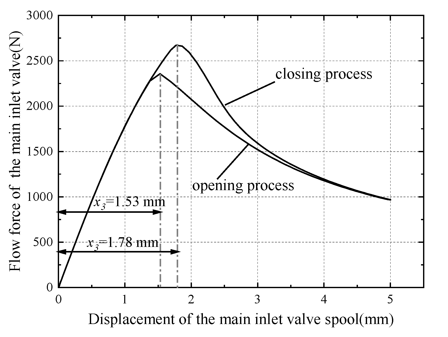
3.3. Results and Discussion

The maximum supply pressure is 25 MPa, and the rated flow rate is less than 1000 L/min because of the limitation of the test conditions. Therefore, the response speed of the proportional valve is slower than expected and the full stroke test cannot be completed. The supply pressure and flow rate in the simulation model are adjusted to make them consistent with the test conditions in the following test, so as to compare the simulation results with the test results.
Figure 7 shows the steady-state control characteristics of the proportional valve. The displacement of the main inlet valve spool is also 0 mm when the displacement of the pilot inlet valve spool is 0 mm. Then, the displacement of the main inlet valve spool gradually increases to 4.3 mm with the displacement of the pilot inlet valve spool. There is a good linear relationship between the displacement of the pilot inlet valve spool and the main inlet valve spool, which indicates that there is good position control characteristics of the proportional valve.
Figure 8, Figure 9 and Figure 10 shows the approximate step response of the proportional valve under different supply pressures. Figure 8 shows the comparison between the test and the simulation results under 4.3 mm step signal. The test result is carried out at 14 MPa. The response speed in simulation is faster than the test result because the delay characteristics of the motor and the lead screw nut are ignored in the simulation process. Besides, the flow of the accumulator gradually decreases with the time. Therefore, the response time and delay time of the second cycle are obviously longer than that of the first cycle. However, the test results and the simulation results are still in good agreement, which proves the correctness of the simulation model under 14 MPa.
Figure 9 shows the approximate step response characteristics of the proportional valve at 2 mm, 3 mm, and 4 mm when the supply pressure is 25 MPa. In the 2 mm step response, the simulation results are in good agreement with the test results, however, the supply flow is smaller and the response speed significantly decreases as the stroke increases. The test result proves the correctness of the simulation model under 25 MPa.
Figure 11 is the ramp response of the proportional valve. The displacement of the main inlet valve spool always approximately coincides with that of the pilot inlet valve spool under a ramp signal of 600 ms, which indicates that there is good follow-up characteristics between the main inlet valve and the pilot inlet valve. It also indicates that the principle of displacement feedback is feasible. The maximum value of the displacement difference between the pilot stage and the main stage is 0.25 mm during the opening and closing process. In other words, under the ramp signal, the pilot stage always maintains a small valve opening, indicating that the displacement of the main stage spool can be controlled in real time by the pilot stage.
There is a high agreement by comparing the simulation and test results. Therefore, the reliability of the simulation model can be verified at 14 MPa and 25 MPa respectively.

4. Performance Prediction

In this section, the performance of the proportional valve under rated conditions will be predicted through the simulation model verified in the previous section. The rated flow rate is set to be 1000 L/min, and the nominal pressure is 31.5 MPa.

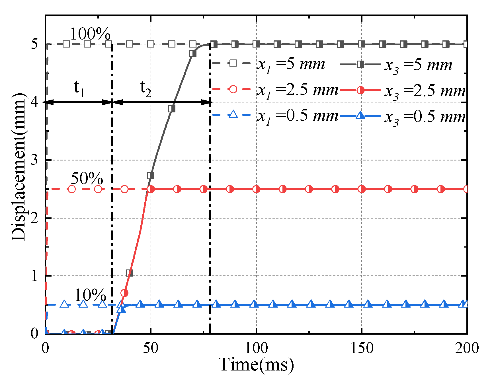
4.1. Performance Analysis

Figure 12 depicts the step response characteristics of the proportional valve. t1 mainly represents the response time of the main outlet valve from the initial position to the right end, which is about 31 ms. t2 is the full stroke opening time of the main inlet valve of the proportional valve, and it is about 46 ms. The proportional valve has good response characteristics without obvious overshooting under different strokes.
The pressure of the control chamber under the full stroke step signal is shown in Figure 13. First, the pressure rises to 0.5 MPa, and the main outlet valve moves to the end. Then, the pressure of the control chamber rises again to about 22 MPa, reaching the opening pressure of the main inlet valve, and the main inlet valve spool starts to move. It takes the time t3 + t4 when the pressure of the control chamber drops from the highest point to the lower level, which presents a non-linear characteristic. The reason for this phenomenon is caused by the flow force, which is analyzed in Figure 15 and Equation (1) in the flowing content.
The main outlet valve spool always remains closed in normal operation, and its characteristics are obtained from Figure 13. Therefore, the simulation model of the main outlet valve is deleted, and its dynamic characteristics are ignored in the following analysis, so that a more accurate response characteristic of the proportional valve can be obtained.
The step response characteristics of the valve under full stroke are shown in Figure 14. It takes 4 ms for the pressure of the control chamber to build-up. The opening time to is about 50 ms, and the closing time tc is about 35 ms. The main inlet valve spool follows the displacement of the pilot inlet valve spool, and the pilot outlet valve spool and the main inlet valve spool move together during the opening process of the proportional valve. Then, the main inlet valve spool follows the pilot outlet valve spool, and the pilot inlet valve spool and the main inlet valve spool move together during the closing process. It shows a good displacement follow-up performance between the pilot stage and the main stage.
Figure 15 shows the relationship between the flow force of the poppet valve and the valve opening under the step response of the proportional valve. The direction of the flow force is along the direction of the closing process of the main inlet valve, which is the same direction with the main spring force. When the supply flow remains constant, the flow force increases linearly with the opening of the main inlet valve and then decreases in an inversely proportional trend. It reaches the maximum value when the displacement of the main inlet valve spool is between 1.5–2 mm. This is consistent with the conclusion in the literature [25].
The dynamic equations of the main inlet spool are expressed in the opening process and the closing process as follows:
p k A k = m d 2 x 3 d t 2 + B v d x 3 d t + k p x 3 + F f ( x 3 )
k p x 3 + F f ( x 3 ) = m d 2 x 3 d t 2 + B v d x 3 d t + p k A k
where, m, is the equivalent mass of the main inlet valve; Bv, viscous friction coefficient; kp, spring stiffness of main spring; and Ff(x3), flow force on the main inlet valve
The flow force is expressed as a function of x3. It is a resistance, and its value increases from 0 N in the opening process of the proportional valve. However, the flow force is the driving force in the closing process, which starts to increase from the initial value of 1000 N, which can be seen from Figure 8. Therefore, the closing time of the proportional valve is much shorter than the opening time. Moreover, the pressure of the control chamber also has a nonlinear trend, which can be seen from Figure 6, because the change of flow force is in a nonlinear trend. The transient flow force during the closing process is greater than the transient flow force during the opening process, because the velocity of the closing process is bigger than the opening process, and the transient flow force is approximately proportional to the velocity. Therefore, the flow force during the closing process is bigger than that during the opening process.
The instantaneous opening and closing of the valve will cause water hammer under high flow conditions, which can easily cause accelerated aging and failure of hydraulic components, so the proportional valve often works under ramp signals. The opening time of the main inlet valve spool is about 50 ms under step signal. Therefore, the time of the input ramp signal should be greater than 50 ms.
Figure 16 demonstrates the response of the proportional valve under the ramp signal of 50 ms, 100 ms, and 200 ms. The displacement of the main inlet valve spool approximately coincides with the pilot inlet valve spool under different ramp signals. In other words, the input signal can be adjusted in real time to change the output signal under normal operating conditions. The displacement difference between the pilot inlet valve and the main inlet valve under the ramp signal is less than 0.6 mm, and its value decreases as the time increases.
It can be seen from the ramp response characteristics of the proportional valve that the main inlet valve can approximately follow the pilot inlet valve during the opening process when the response time of the control signal is greater than 50 ms. In other words, the period of the input signal should be greater than 100 ms to maintain good follow-up characteristics. Then, the frequency response characteristics of the proportional valve at 1 Hz, 5 Hz, 10 Hz, and 20 Hz will be studied.
Figure 17 shows the response characteristic of the proportional valve to the sinusoidal signal. The output signal can follow the input signal when the frequency of the input signal is less than 10 Hz. Figure 17c shows that the displacement amplitude ratio between the main inlet valve spool and the pilot inlet valve spool is 0.996 when the response frequency of the pilot inlet spool is 10 Hz. The pilot inlet valve port cannot be completely closed during a complete period, and the system becomes unstable as the frequency continues to increase. Therefore, the normal operating frequency of the proportional valve should be less than 10 Hz to stay stable.

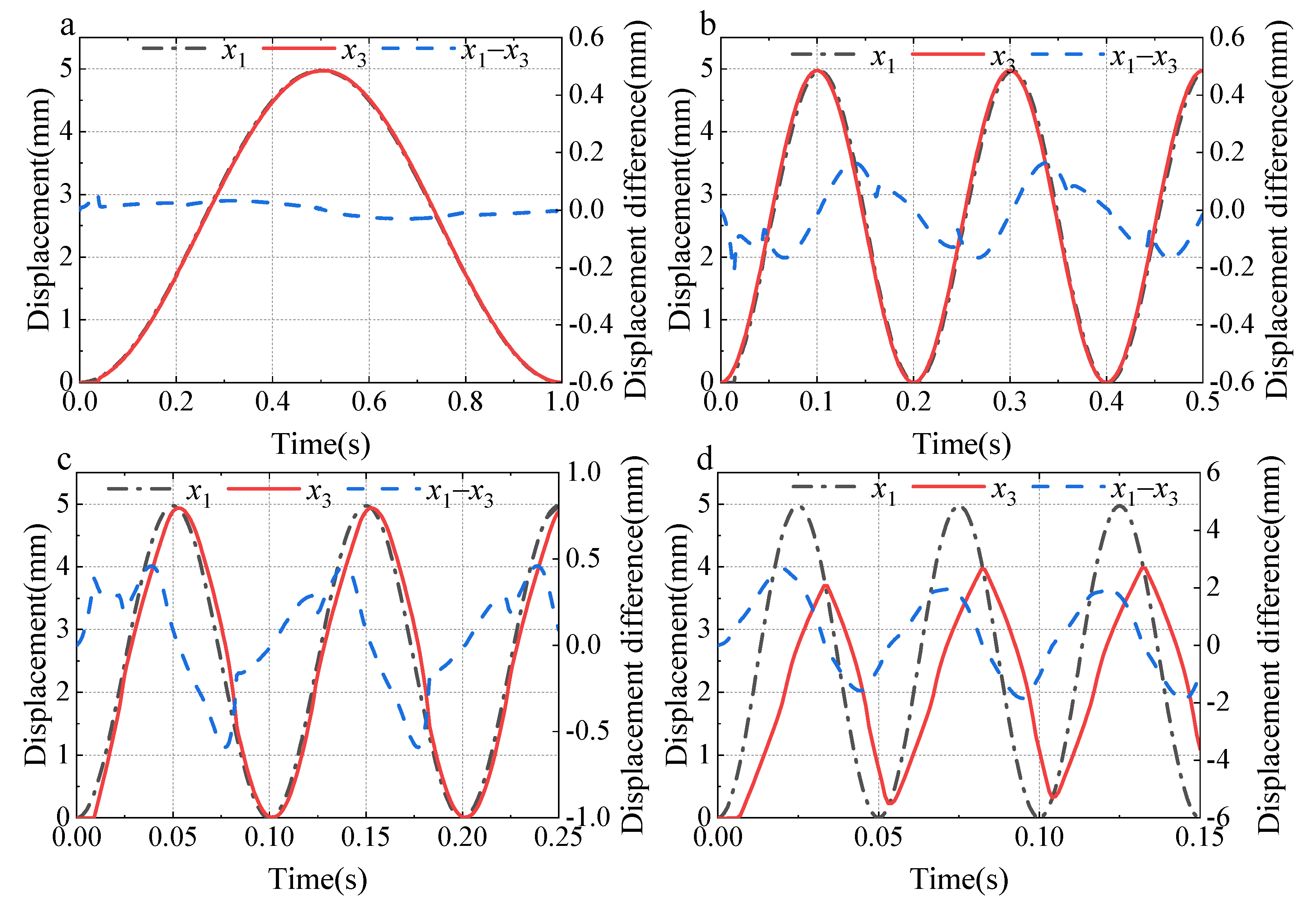
4.2. Stability Analysis

According to the structural principle of the proportional valve, the pilot outlet valve must be reliably closed to ensure the stability of the system during the opening process of the proportional valve. Therefore, it is necessary to analyze the conditions for the reliable closing of the pilot outlet valve.
The pilot outlet valve is simplified to a mass spring system according to Figure 18. The external forces FL and FR acting on the pilot outlet valve can be expressed as:
{ F L ( t ) = k ( x 0 x ( t ) ) F R ( t ) = p k ( t ) A 4
The condition for the pilot outlet valve to be reliably closed is FL(t) > FR(t) during the opening process of the proportional valve. At the moment when the main inlet spool is opened, FL0 and FR0 can be expressed as:
{ F L 0 = k x 0 F R 0 = A 4 A h A p A k p
The pre-compression of the pilot spring should be greater than 5 mm, because the maximum valve opening of the main inlet valve is 5 mm. Therefore, the pre-compression is 6 mm to ensure reliability in Equation (4), and the calculation result is k > 3 N/mm.
The dynamic change process of FR and FL during the opening process is analyzed through the simulation model. FL should always be greater than FR to ensure the stability of the system during the opening process. In other words, the FL curve should always stay above the FR curve. The force change curve is shown in Figure 19 under step signal when the stiffness of the pilot spring changes from 3 N/mm to 7 N/mm.
It is shown in Figure 19 that the FL curve is always above the FR curve when the stiffness of the pilot spring k ≥ 4 N/mm, ensuring FL(t) > FR(t) in the process of opening. In other words, the pilot outlet valve is reliably closed during the opening process of the proportional valve, and the system remains stable.
Under the 5 mm step signal, the FL and FR curves are shown in Figure 15 when k ≤ 4 N/mm, and the red shaded part is FL < FR. Then, there will be a displacement difference between the displacement curve of the main inlet valve and the displacement curve of the pilot outlet spool after a certain delay time. It is expressed with blue shade in Figure 20. The final displacement of the main inlet valve spool is 4.95 mm, and there is a 0.05 mm displacement difference between the main inlet valve spool and the pilot inlet valve spool. Therefore, the pilot inlet valve port remains open. In addition, there is also a displacement difference of 0.05 mm between the pilot outlet valve spool and the main inlet valve spool. Therefore, the flow rate flowing into the control chamber through the pilot inlet valve is equal to the flow rate flowing out of the control chamber through the pilot outlet valve, and the system is in an unstable equilibrium state.
Therefore, the stiffness of the pilot spring should be at least 4 N/mm to ensure that the pilot outlet valve can be reliably closed during the opening process. The best structural parameters can be obtained by the method of parameter matching under different working conditions to ensure the stability of the system.

5. Conclusions

There are many problems such as high pressure shock and poor flow controllability of the on-off valve for traditional hydraulic supports. A novel large flow water hydraulic proportional valve with two-position and three-way function is proposed, which adopts the displacement follow-up principle. The new valve has the special three spool follow-up mechanism. The above problems can be solved by the new valve. It provides a certain reference for the design and research of proportional valves. The following conclusions can be drawn:
A novel proportional directional valve composed of two stages is creatively proposed. The pilot stage composed of two pilot valves is used to control the chamber of the main stage, and the main valve is composed of two main valve spools. An electromechanical conversion device composed of a DC servo motor and a screw slider is used to drive pilot stages. Then, the displacement follow-up principle is used between the pilot stage and the main stage. Therefore, the displacement of the main inlet valve is always equal to that of the pilot stage in the steady state. According to the research, there are good position control characteristics and stability of the proportional valve.
The prototype of the high-pressure and large-flow proportional valve was processed, and a high-pressure and large-flow test apparatus was built. The experimental dynamic and static characteristics of the proportional valve are compared with the simulation results under the same working conditions. The test results verify the reliability of the simulation model and the feasibility of the design scheme.
A numerical simulation model is built to predict the static and dynamic performance of the proportional valve under rated pressure and flow. The opening time of the proportional valve is about 50 ms, and the closing time is about 35 ms with the step signal under rated pressure and flow. The pressure trend of the control chamber is nonlinear with the opening process of the main inlet valve, and the closing time of the proportional valve is shorter than the opening time, which is affected by the nonlinear flow force. When the ramp signal inputted is greater than 50 ms, the displacement of the main inlet valve spool is approximately equal to that of the pilot inlet valve spool during the opening process of the proportional valve. Then, the working frequency of the proportional valve should be less than 10 Hz to keep the valve stable through frequency analysis.
Finally, a parameter matching method between the pilot stage and the main stage is proposed. The initial value of the structural parameters of the pilot outlet valve, which can ensure the stability of the system, is analyzed through the mathematical model. The force of the pilot outlet valve during dynamic operation is analyzed by the simulation model, and the stiffness of the pilot spring of the proportional valve under no-load condition is finally determined.

Author Contributions

Conceptualization, H.Z. and Y.L.; Methodology H.Z., R.Z. and Z.T.; Validation Y.L. and Z.L.; Writing—original draft, H.Z.; Writing—review and editing, Y.L. All authors have read and agreed to the published version of the manuscript.

Funding

This research was funded by the National Natural Science Foundation of China (51905368), China Postdoctoral Science Foundation (2021M702419), the Shanxi Provincial Education Department (2021Y214), and the Shanxi Science and Technology Department (1331).

Institutional Review Board Statement

Not applicable.

Informed Consent Statement

Not applicable.

Data Availability Statement

Not applicable.

Conflicts of Interest

The authors declare no conflict of interest.

References

  1. Lim, G.H.; Chua, P.S.K.; He, Y.B. Modern Water Hydraulics—The New Energy-Transmission Technology in Fluid Power. Appl. Energy 2003, 76, 239–246. [Google Scholar] [CrossRef]
  2. Majdic, F.; Pezdirnik, J.; Kalin, M. An Analytical Comparison of Hydraulic Systems Based on Water and on Oil. Proc. JFPS Int. Symp. Fluid Power 2008, 2008, 679–684. [Google Scholar] [CrossRef] [Green Version]
  3. Liu, Y.; Zhao, X.; Wu, D.; Li, D.; Li, X. Study on the Control Methods of a Water Hydraulic Variable Ballast System for Submersible Vehicles. Ocean Eng. 2015, 108, 648–661. [Google Scholar] [CrossRef]
  4. Park, S.-H. Development of a Proportional Poppet-Type Water Hydraulic Valve. Proc. Inst. Mech. Eng. Part C J. Mech. Eng. Sci. 2009, 223, 2099–2107. [Google Scholar] [CrossRef]
  5. Fairfield, N.; Kantor, G.; Jonak, D.; Wettergreen, D. Autonomous Exploration and Mapping of Flooded Sinkholes. Int. J. Robot. Res. 2010, 29, 748–774. [Google Scholar] [CrossRef]
  6. Han, M.; Liu, Y.; Wu, D.; Tan, H.; Li, C. Numerical Analysis and Optimisation of the Flow Forces in a Water Hydraulic Proportional Cartridge Valve for Injection System. IEEE Access 2018, 6, 10392–10401. [Google Scholar] [CrossRef]
  7. Liao, Y.; Lian, Z.; Feng, J.; Yuan, H.; Zhao, R. Effects of Multiple Factors on Water Hammer Induced by a Large Flow Directional Valve. Stroj. Vestn. J. Mech. Eng. 2018, 64, 329–338. [Google Scholar] [CrossRef]
  8. Liao, Y.; Ren, H.; Zhang, D. Calculation method of flow force for the directional valve used on hydraulic roof support and its application. J. China Coal Soc. 2019, 44, 1609–1615. [Google Scholar] [CrossRef]
  9. Tang, W.; Xu, G.; Zhang, S.; Jin, S.; Wang, R. Digital Twin-Driven Mating Performance Analysis for Precision Spool Valve. Machines 2021, 9, 157. [Google Scholar] [CrossRef]
  10. Li, S.; Ruan, J.; Meng, B. Two-dimensional electro-hydraulic proportional directional valve. J. Mech. Eng. 2016, 52, 202–212. [Google Scholar] [CrossRef]
  11. Li, L.; Lin, Z.; Jiang, Y.; Yu, C.; Yao, J. Valve Deadzone/Backlash Compensation for Lifting Motion Control of Hydraulic Manipulators. Machines 2021, 9, 57. [Google Scholar] [CrossRef]
  12. Han, M.; Liu, Y.; Wu, D.; Zhao, X.; Tan, H. A Numerical Investigation in Characteristics of Flow Force under Cavitation State inside the Water Hydraulic Poppet Valves. Int. J. Heat Mass Transf. 2017, 111, 1–16. [Google Scholar] [CrossRef]
  13. Yao, J.; Yin, Y.; Dong, Z.; He, Y. Design of a 70 MPa Two-Way Proportional Cartridge Valve for Large-Size Hydraulic Forging Press. J. Beijing Inst. Technol. 2020, 29, 260–272. [Google Scholar] [CrossRef]
  14. Eriksson, B. Control Strategy for Energy Efficient Fluid Power Actuators: Utilizing Individual Metering; Springer: Berlin/Heidelberg, Germany, 2007. [Google Scholar]
  15. Wang, S.; Zhao, H.; Quan, L. Research on the dynamic and static characteristics of electro-hydraulic proportional direction valve with flow feedback. J. Mech. Eng. 2014, 50, 205–212. [Google Scholar] [CrossRef]
  16. Huang, J.; Wang, X.; Wang, H.; Hao, H. Development of a Flow Control Valve with Digital Flow Compensator. Flow Meas. Instrum. 2019, 66, 157–169. [Google Scholar] [CrossRef]
  17. Zhang, J.; Xue, X.; Kou, C.; Yao, J.; Kong, X. Modeling of DN63 Displacement-follower Ultra High Pressure Proportional Cartridge Valves. China Mech. Eng. 2019, 30, 2424. [Google Scholar] [CrossRef]
  18. Han, M.; Liu, Y.; Zheng, K.; Ding, Y.; Wu, D. Investigation on the Modeling and Dynamic Characteristics of a Fast-Response and Large-Flow Water Hydraulic Proportional Cartridge Valve. Proc. Inst. Mech. Eng. Part C J. Mech. Eng. Sci. 2020, 234, 4415–4432. [Google Scholar] [CrossRef]
  19. Zhao, R.; Liao, Y.; Lian, Z.; Li, R.; Guo, Y. Research on the Performance of a Novel Electro-Hydraulic Proportional Directional Valve with Position-Feedback Groove. Proc. Inst. Mech. Eng. Part E J. Process Mech. Eng. 2021, 235, 1930–1944. [Google Scholar] [CrossRef]
  20. Zhang, Z.; Meng, F.; Hou, J.; Wu, H.; Gong, Y. Design, simulation and experiments of water hydraulic throttle valve with direct voice coil motor actuation. J. China Coal Soc. 2017, 42, 275–281. [Google Scholar] [CrossRef]
  21. Suzuki, K.; Akazawa, S.; Nakao, Y. Development of cam-drive type proportional valve for water hydraulics. Int. J. Autom. Technol. 2012, 6, 450–456. [Google Scholar] [CrossRef]
  22. Wu, W.; Wei, C.; Zhou, J.; Hu, J.; Yuan, S. Numerical and Experimental Nonlinear Dynamics of a Proportional Pressure-Regulating Valve. Nonlinear Dyn. 2021, 103, 1415–1425. [Google Scholar] [CrossRef]
  23. Wang, H.; Wang, X.; Huang, J.; Quan, L. Flow Control for a Two-Stage Proportional Valve with Hydraulic Position Feedback. Chin. J. Mech. Eng. 2020, 33, 93. [Google Scholar] [CrossRef]
  24. Hagstrom, N.P.; Fikru, N.; Hargus, A.M.; Chase, T.R. A Novel Piezoelectrically Driven Miniature Proportional Pneumatic Control Valve Utilizing a Microfabricated Orifice Array. IEEEASME Trans. Mechatron. 2019, 24, 1931–1941. [Google Scholar] [CrossRef]
  25. Wu, D.; Wang, X.; Ma, Y.; Wang, J.; Tang, M.; Liu, Y. Research on the Dynamic Characteristics of Water Hydraulic Servo Valves Considering the Influence of Steady Flow Force. Flow Meas. Instrum. 2021, 80, 101966. [Google Scholar] [CrossRef]
Figure 1. Principle of the water hydraulic proportional directional valve: (a) initial state; (b) opening process; (c) closing process.
Machines 10 00037 g001
Figure 2. Control schematic of the proportional valve.
Machines 10 00037 g002
Figure 3. Block diagram of the proportional valve.
Machines 10 00037 g003
Figure 4. Principle of the hydraulic test system.
Machines 10 00037 g004
Figure 5. The proportional valve prototype.
Machines 10 00037 g005
Figure 6. The simulation model of the proportional valve in AMESim.
Machines 10 00037 g006
Figure 7. Test results of steady-state control characteristics.
Machines 10 00037 g007
Figure 8. Step response test under 14 MPa.
Machines 10 00037 g008
Figure 9. Step response test under 25 MPa.
Machines 10 00037 g009
Figure 10. Pressure of the step response test under 25 MPa.
Machines 10 00037 g010
Figure 11. Response of test result under ramp signal.
Machines 10 00037 g011
Figure 12. The step response of the proportional valve.
Machines 10 00037 g012
Figure 13. The pressure of the control chamber.
Machines 10 00037 g013
Figure 14. The step response characteristics of the valve under full stroke.
Machines 10 00037 g014
Figure 15. The flow force of the main inlet valve port.
Machines 10 00037 g015
Figure 16. The ramp response of the proportional valve.
Machines 10 00037 g016
Figure 17. The frequency response characteristics of the proportional valve: (a) 1 Hz; (b) 5 Hz; (c) 10 Hz; (d) 20 Hz.
Machines 10 00037 g017
Figure 18. Simplification of the pilot outlet valve.
Machines 10 00037 g018
Figure 19. The relationship between force and displacement.
Machines 10 00037 g019
Figure 20. The dynamic change process of FL and FR.
Machines 10 00037 g020
Table 1. The test device parameters.
DeviceParameters
DC servo motorRated power: 400 W
Rated speed: 3000 rpm
Rated torque: 1.27 Nm
Screw Sliderstroke: 100 mm
lead: 5 mm
maximum thrust: 452 N
repeated positioning accuracy: ±0.02 mm
Data collectorSampling channel: 8 channels
Sampling frequency: <102.4 kHz
resolution ratio: 0.01%
Pressure transducerPressure range: 0–60 MPa
Sampling frequency: <100 kHz
accuracy class: 0.5%FS
Displacement transducerDisplacement range: 0–100 mm
resolution ratio: 0.02%
Sampling frequency: <500 Hz
LVDTDisplacement range: 0–10 mm
linearity: ±1%
Publisher’s Note: MDPI stays neutral with regard to jurisdictional claims in published maps and institutional affiliations.

