Article

Lightweight Design Optimization of Nonpneumatic Tires under Radial-Stiffness Constraints

1
Ji Hua Laboratory, Foshan 528200, China
2
State Key Laboratory of Automotive Simulation and Control, Changchun 130025, China
*
Author to whom correspondence should be addressed.
Machines 2022, 10(10), 889; https://doi.org/10.3390/machines10100889
Submission received: 15 September 2022 / Revised: 27 September 2022 / Accepted: 27 September 2022 / Published: 2 October 2022
(This article belongs to the Section Machine Design and Theory)

Abstract

:
Nonpneumatic tires (NPTs) have good safety and a good load-carrying capacity, and they replace the function of air in pneumatic tires with a solid spoke component. The radial stiffness and weight are the important indexes for evaluating the performance of an NPT. In this research, we designed an NPT according to the requirements of vehicle Chery eQ1 based on weight minimization. Taking the radial stiffness related to the bearing-capacity performance as the constraint condition, a topology-optimization algorithm is proposed to find the best thickness distribution of the spokes with the objective of minimizing the mass. First, the mechanical properties of the material were obtained with the test. Then, the FE model of an NPT with a Fibonacci spoke structure was built and validated with a radial-stiffness test on a five rigid test machine. The optimization algorithm was carried out by searching for the best thickness distribution of the spoke after verifying the reliability of the FE model. Finally, the optimized tire was manufactured, and the stiffness test was carried out to verify the feasibility of the optimization results. The results show that the spoke mass can be reduced by 9% by using the proposed optimization algorithm while satisfying the radial-stiffness constraint.

1. Introduction

Nonpneumatic tires (NPTs) can completely achieve the functions of traditional pneumatic tires, such as supporting the vehicle, providing sufficient traction for driving and braking, cushioning the vehicle, and so on. More importantly, they can work without maintaining the air pressure, and with this characteristic, the serious traffic accidents caused by punctures, scratches, leaks, and even blowouts in tires can be overcome [1].
Figure 1 shows a variety of NPTs. A new concept NPT Tweel with the significant advantages of no bursting and no leakage was produced by Michelin [2]. Since then, more attention has been paid to NPTs. In 2008, Resilient Technology and the University of Wisconsin jointly developed a new honeycomb NPT made of polyurethane, which was designed with the tensile deformation of a honeycomb structure [3,4,5]. Bridgestone launched air-free concept NPTs in 2012 and 2014. In 2015, iFlex was launched by the Hantai Company [6,7]. In 2021, Jihua Lab developed an NPT with the structural characteristics of variable-thickness tires for vehicle Chery eQ1, and we present details on the lightweight design of this NPT in this paper.
The radial stiffness is used to evaluate the bearing capacity of an NPT. The radial stiffness also affects the rolling damping and buffering performance. Over the last decade, researchers have studied the load-bearing properties of NPTs. Jang designed the stiffness of an NPT with topology-optimization technology [8]. Zhao investigated the static stiffness of a new NPT with a hinge using numerical simulations and experiments [9]. In order to obtain NPTs with high load capacities, the bionic structure was introduced into the spoke design. Ganniari quantified the effect of a wide range of internal geometrical parameters on a honeycomb tire’s weight and mechanical behavior [10]. Zang proposed a design method for a honeycomb structure to direct the design of NPTs [11]. Zhang established an NPT with the characteristics of a kangaroo’s lower-limb structure and carried out a stiffness simulation for the NPT [12]. Chiral structures have been developed for NPTs due to their unique optical and mechanical properties. Wu developed a gradient anti-tetrarchical structure to replace the pneumatic parts of standard pneumatic tires, and the tires had a good load-carrying capacity [13].
Weight is also one of the important performance factors of NPTs. The reduction in the unsprung mass of a vehicle is conducive to fuel economy and smoothness [14]. The thickness of the spokes is also one of the main design variables of NPTs, and it has a great impact on not only their load-bearing capacity, but also their weight. However, variable-thickness structures have excellent performances and are widely used in automobiles, aviation, and other industrial fields [15,16,17]. The variable-thickness-structure design methods (e.g., the surrogate-model method [18,19,20] and intelligent-algorithm method [21,22,23]) have been widely used in the past few decades. In recent years, the topology-optimization method [24,25,26] has been applied to the design of variable-thickness structures because it is more efficient for optimization with a large number of variables. The abovementioned design method can make the components lightweight while satisfying the established requirements for the mechanical properties.
In this research, a lightweight NPT with radial-stiffness requirements was created. The improved topology-optimization algorithm was used for the NPT-spoke-thickness optimization, and it was proven to be effective with a radial-stiffness test. The continuously changing thickness of the spoke was taken as the design variable, while the radial stiffness was taken as the design constraint. The minimum mass was the optimization objective. In Section 2, we present the optimization-design-problem statement, the sensitivity analysis of the thickness-design variables, and the distribution constraints of the thickness. Section 3 describes how the mechanical properties of the polyurethane materials of the spoke were obtained with a test. The finite-element (FE) model of the NPT was built for lightweight design work, and the accuracy of the model was verified with a tire-radial-stiffness test. Section 4 describes how the optimized thickness distribution of the spokes was carried out with the proposed method, and how the lightweight tire was manufactured and verified again. The conclusions are given in Section 5.

2. Design Problem and Optimization Method

2.1. Design-Problem Statement

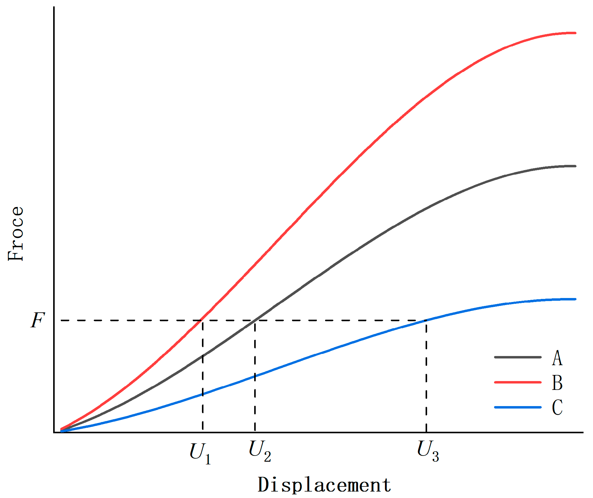
The appropriate radial stiffness of a tire can balance the performance requirements between the driving safety, handling stability, fuel economy, and vehicle ride comfort. Figure 2 shows the force-displacement curve of three different tire-radial-load tests. It can be seen from the figure that the radial stiffness of Tire B is the highest, and that of Tire C is the lowest. It is incorrect to think that the best curve is the one with the greatest stiffness. Actually, the best stiffness curve should be the best matching for the corresponding car. Therefore, it is reasonable to use stiffness as a constraint in tire optimization.
It is assumed that the radial-force-displacement curve of the tire in Figure 3 is tailored for an actual automobile. U* is the maximum radial-deformation displacement of the tire. F* is the radial reaction force with the maximum deformation displacement. The process of the loading tire displacement can be divided into many steps. Ui and Fi represent the radial force and radial deformation of the tire in the i-th step, respectively. These two physical quantities are applied to the derivation of the sensitivity, as described in the next section.
Due to the radial stiffness being tailored for an actual automobile, the mathematical model of the lightweight tire design can be described as shown in Equation (1). f(te) is the target, representing the mass of the tire; ρ e is the element density; s e is the area of the element of the number (e); te is the design variable for the spoke thickness; tmax and tmin are the maximum thickness and minimum thickness, respectively; U* and F* are described in the previous section; N is the total shell-element number.
Minimize f ( t e ) = e = 1 e = N ρ e t e s e Subject to U max = U * F max = F * t e [ t min , t max ] e = 1 , …… , N

2.2. Sensitivity Analysis for Thickness

U* is the external displacement loading that can be loaded in the FE model. The force constraint can be added to the objective function by introducing a Lagrangian multiplier (λ):
f ( t e ) = t e = 1 t e = N ρ e t e s e + λ ( F F * )
The modified objective function is equivalent to the original objective function, and the Lagrangian multiplier (λ) can be any constant if the force constraint is satisfied. The derivative of the modified objective function (f(te)) is:
d f ( t e ) d t e = t e = 1 t e = N ρ e s e + λ d F d t e
To calculate the λ d F d t e , we introduce a virtual unit displacement (uk), and the expression of F can be expressed as:
F = ( u k ) T F
The radial loading of the tire is related to the geometric and material nonlinearity. The reaction force is calculated as follows in the FE analysis, where K1 is the stiffness matrix of the unloaded spoke, and U0 = 0. The n is the total number of load increments.
Δ F i = K i ( U i U i 1 ) Δ F i 1 = K i 1 ( U i 1 U i 2 ) . . Δ F 1 = K 1 ( U 1 U 0 ) F = Δ F 1 + Δ F 2 + …. Δ F i = i = 1 i = n K i ( U i U i 1 )
By simultaneously solving Equations (3)–(5), the derivative of the objective function (f(te)) can be rewritten as:
d f ( t e ) d t e = t e = 1 t e = N ρ e s e + λ i = 1 i = n ( u k ) T K i ( U i U i - 1 ) d t e
The spoke was modeled with the shell elements, and the stiffness matrix for the shell consists of the membrane, bending, and shear stiffness, which can be expressed by:
K ( t e ) = K m ( t e ) + K b ( t e ) + K s ( t e )
Furthermore, the shell-element-stiffness matrix can be expressed as:
D = E ( 1 v 2 ) [ 1 v 0 v 1 0 0 0 1 v 2 ] , D b = E 12 ( 1 v 2 ) [ 1 v 0 v 1 0 0 0 1 v 2 ] , D s = G k [ 1 0 0 1 ] k = 1.2 K m ( t e ) = t e A e B T D B d A , K b ( t e ) = t e 3 A e B b T D b B b d A , K s ( t e ) = t e A e B s T D s B s d A
where D, Db, and Ds are the material matrixes, v is the Poisson’s ratio, E is the Young’s modulus, G is the shear modulus, and k is the shear-stress-distribution coefficient. By simultaneously solving Equations (6) and (8), the sensitivity of the element of the number (e) is finally obtained. When the area of each FE mesh approaches equality, λ can be taken from (0,1]:
α e = ρ e s e + λ i = 1 i = n ( u k ) T ( A e B e i T D e i B e i d A + 3 t e 2 A e B b , e i T D b , e i B b , e i d A + A e B s , e i T D s , e i B s , e i d A ) ( U e i U e i 1 )

2.3. Sensitivity with Process Constraints

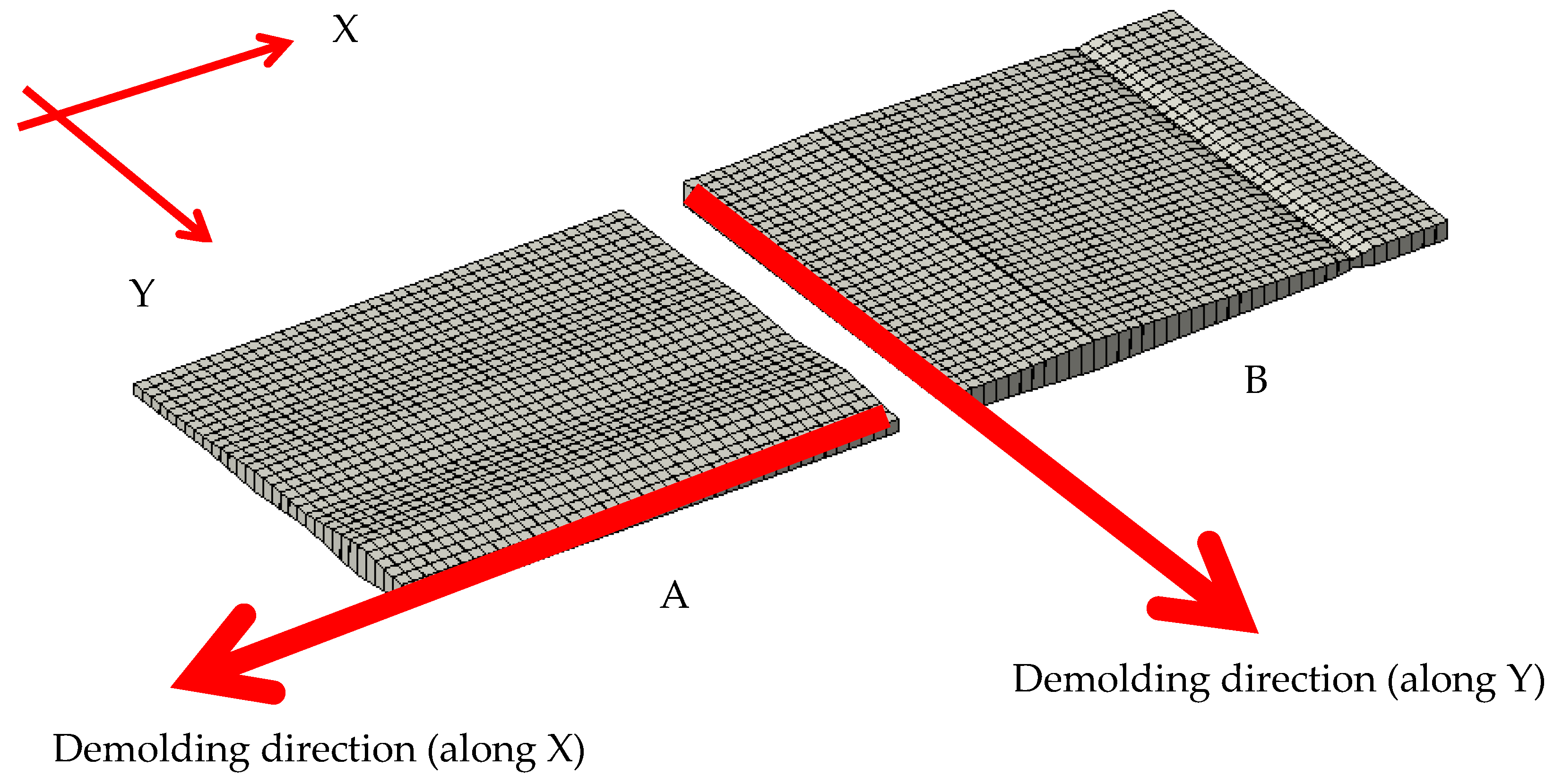
Although taking each shell element as an independent optimization design variable can obtain a structure with a better performance, it will increase the difficulty of the manufacturing. In Figure 4, it can be seen that the thickness of Plate A/B changes along the Y-axis direction/X-axis direction, which is more conducive to demolding from the X-axis direction/Y-axis direction.
In Figure 5, the variable-thickness plate is divided into M1 × M2 grids. Each grid has a thickness sensitivity, and the thickness sensitivity of the variable-thickness plate is in the form of a two-dimensional matrix. In order to make the thickness change only in one direction, we convert the thickness-sensitivity two-dimensional matrix into a one-dimensional matrix, and we constrain the sensitivity according to Formula (10). The xj and yk represent the thickness design variables of the i-th row and k-th column, respectively. m1 is the total number of thickness design variables in the X direction, and m2 is the total number of thickness design variables in the Y direction.
α e ( x j ) = j = 1 j = m 1 α e ( x j , y k ) m 1   or   α e ( y k ) = k = 1 k = m 2 α e ( x j , y k ) m 2

2.4. Sensitivity Filtering

There are areas with rapid thickness changes in the structure, which will increase the risk of failure in the manufacturing process. In order to mitigate the gradient of the thickness change, it is necessary to weight-average the thickness sensitivities of adjacent areas, as shown in Formula (11). L is the filtration range. When the L is increased, the thickness change is slower; otherwise, the thickness change is more intense:
α e ( y k ) = 1 f 1 = 1 f 1 = m 2 H f 1 f 1 = 1 f 1 = m 2 H f 1 α e ( y k ) α e ( x j ) = 1 f 2 = 1 f 2 = m 1 H f 2 f 2 = 1 f 2 = m 1 H f 2 α e ( x j ) H f 1 = max ( L dist ( y k y f 1 ) , 0 ) H f 2 = max ( L dist ( x j x f 2 ) , 0 )

2.5. Update Rule for Thickness

A lighter structure requires a higher load efficiency, for which the inefficient materials should be eliminated, while the efficient materials should be retained in the design domain. The idea of optimizing the thickness is also consistent with this. In order to estimate the contribution of the thickness of each element to the whole design field, we introduce the criterion α a v :
t e i + 1 = { if   b α e α a v α a v b min ( t max , max ( t e i + α e α a v α a v , t min ) if   b α e α a v α a v min ( t max , max ( t e i + b , t min ) if   α e α a v α a v b min ( t max , max ( t e i b , t min )
where b is the maximum step size of the thickness update, and t e i , t e i + 1 are the thicknesses of Step i and Step i + 1, respectively. It is worth noting that, when the mass of the updated thickness is greater than the target value of the current iteration mass, let α min = α a v ; conversely, let α max = α a v .
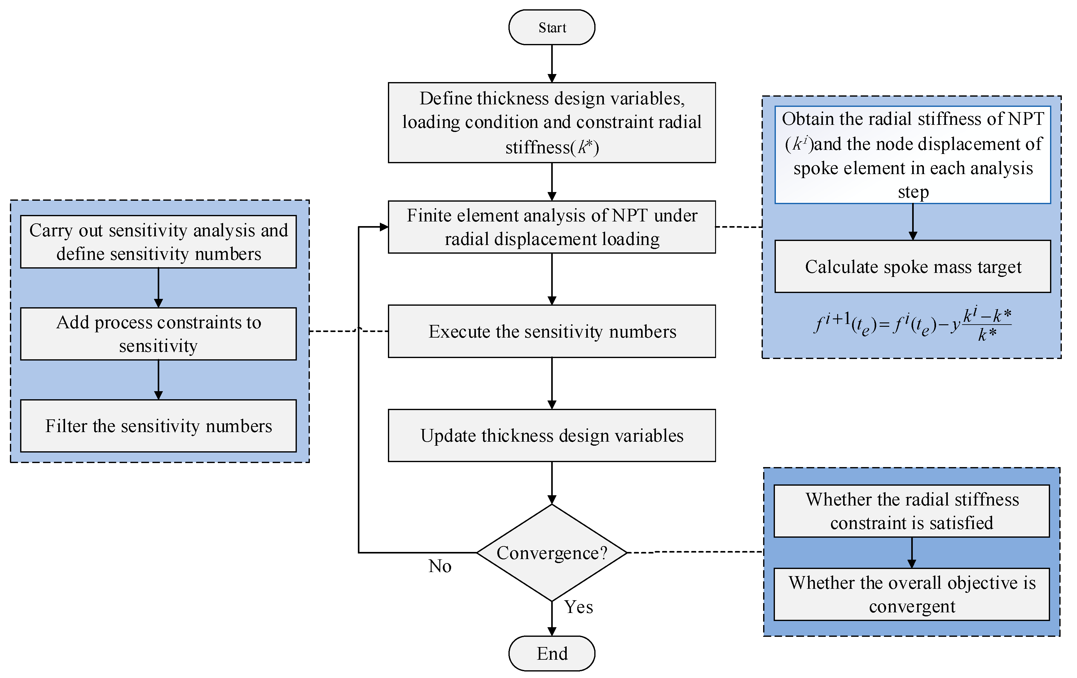
Figure 6 shows the whole process of thickness optimization. y can be determined according to the order of magnitude of the target. In this study, because the target is the mass fraction, y is taken as 1.

3. Automotive NPT

3.1. The Geometry of the Fibonacci-Spoke NPT

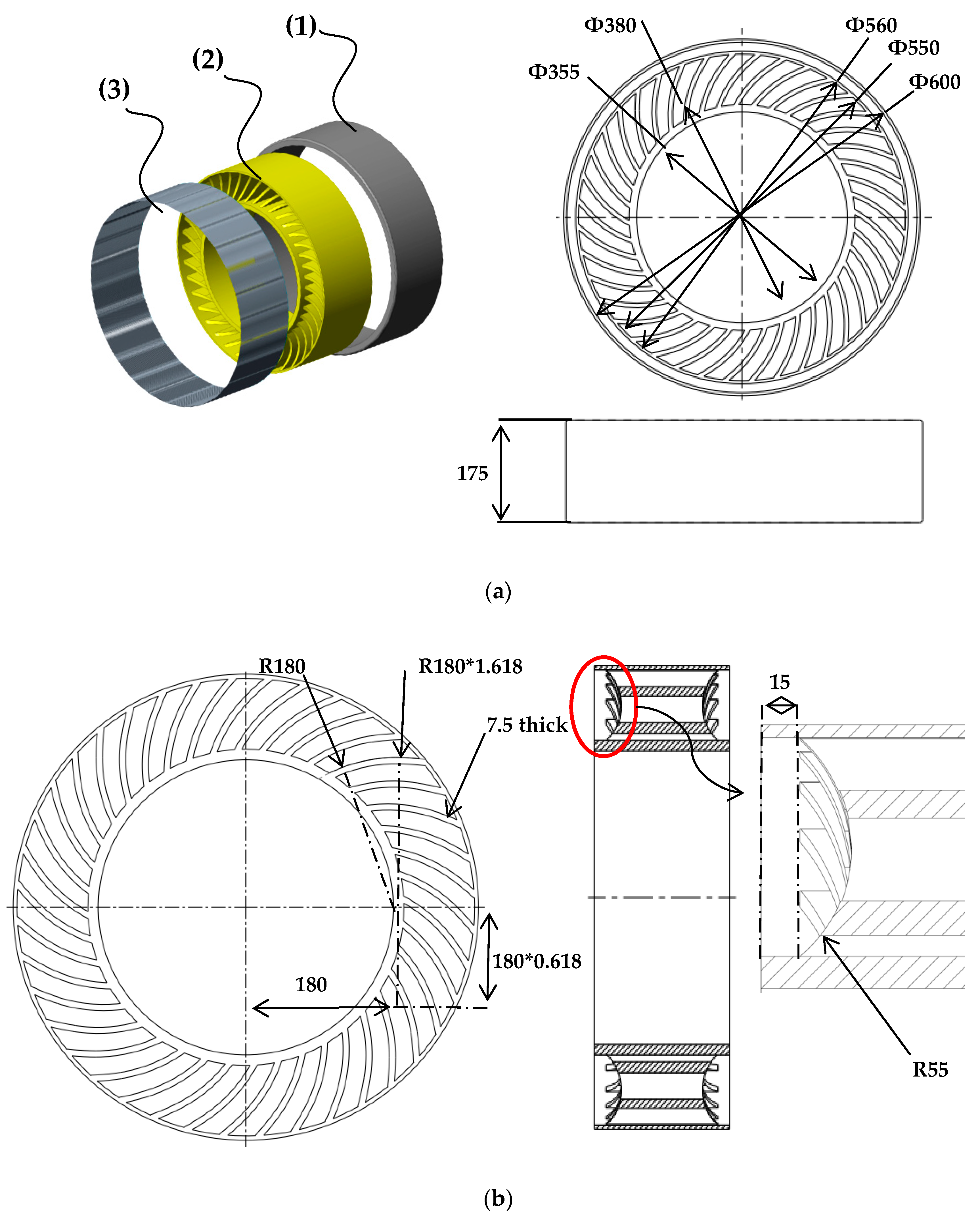
As shown in Figure 7a, the NPT is mainly composed of a tread (1), spoke (2), and ply layer (3). The diameter of the tire is 600 mm, and the width is 175 mm. The tread thickness is 20 mm. The wire-laying angle of the tire cord is 0, and the number of laying layers is 2. There are forty support bars on the spokes, and each of them is 7.5 mm thick. It can be seen from Figure 7b that the radius of the first circular arc of the Fibonacci spokes is 180 mm, and the radius of the second circular arc is 1.618 times that of the first circular arc. The spoke side dimensions and thickness dimensions can also be obtained from Figure 7b.

3.2. NPT Manufacturing

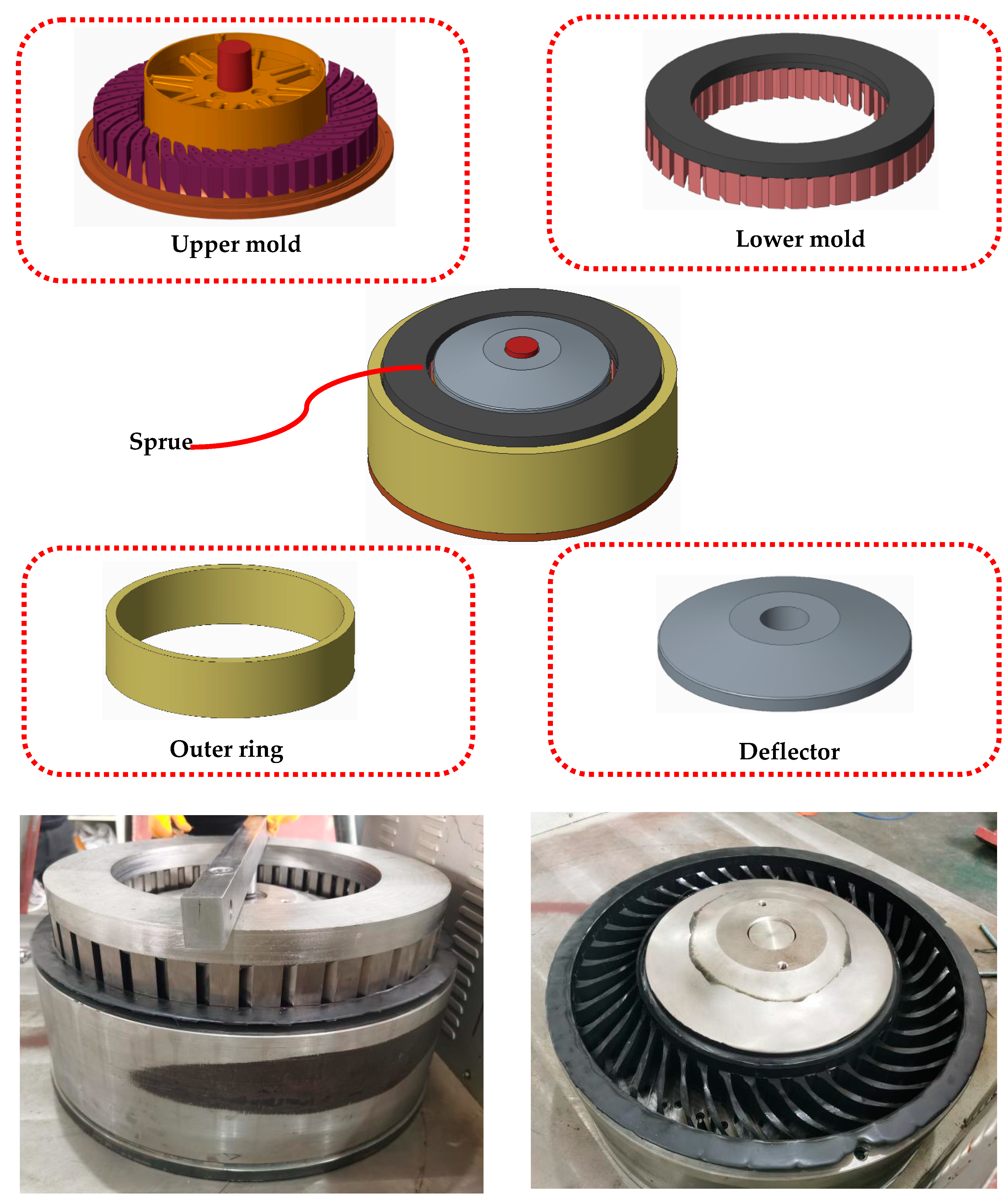
The spoke is formed by pouring. As shown in Figure 8, the spoke mold consists of an upper mold, lower mold, outer ring, and deflector. First, the mold is heated to between 120 °C and 140 °C. Molten material enters the mold cavity through the sprue and freezes within three minutes. After 24 h of vulcanization, the spoke can be demolded. It is notable that the thermal expansion of the material should be considered in the dimensional design of the mold. However, the thickness of the spoke was not 7.5 mm but 6.7 mm, which was caused by the wrong estimation of the thermal-expansion parameters of the material, and we modified the variable-thickness-spoke mold.

3.3. FE Model and Experimental Validation

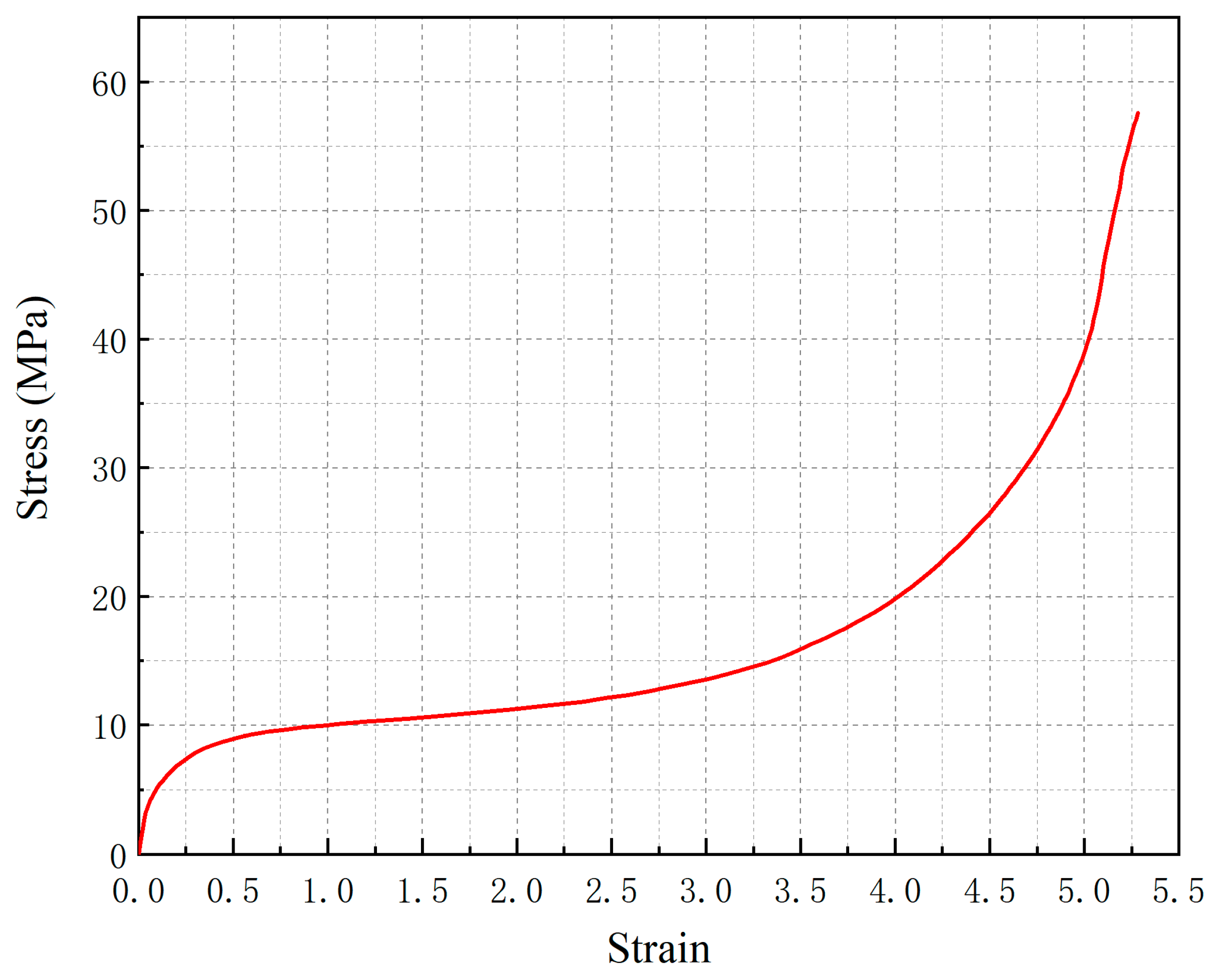
The FE analysis was conducted with the implicit FE code ABAQUS. The spoke was modeled with S4R shell elements, and the other parts were modeled with C3D8RH hexahedron elements. The spoke is made of hyperelastic material, the mechanical properties of which are shown in Figure 9. The tread material is natural rubber, the mechanical performance of which can be defined by C10 and C01 in ABAQUS. In this tire model, C10 = 0.5 and C01 = 0.04. The material of the tire cord in the ply layer is steel, with the mechanical properties of the density ( ρ = 7.8 × 10³ kg/m3), Young’s modulus (E = 210 GPa), and Poisson’s ratio ( μ = 0.30).
In Figure 10, the NPT is fixed on the central axis on a five rigid test machine test bench, and it moves down with a velocity of 50 mm/min to press the test-bench ground until it reaches a 20 mm displacement. The FE model of the NPT was established according to the test conditions.
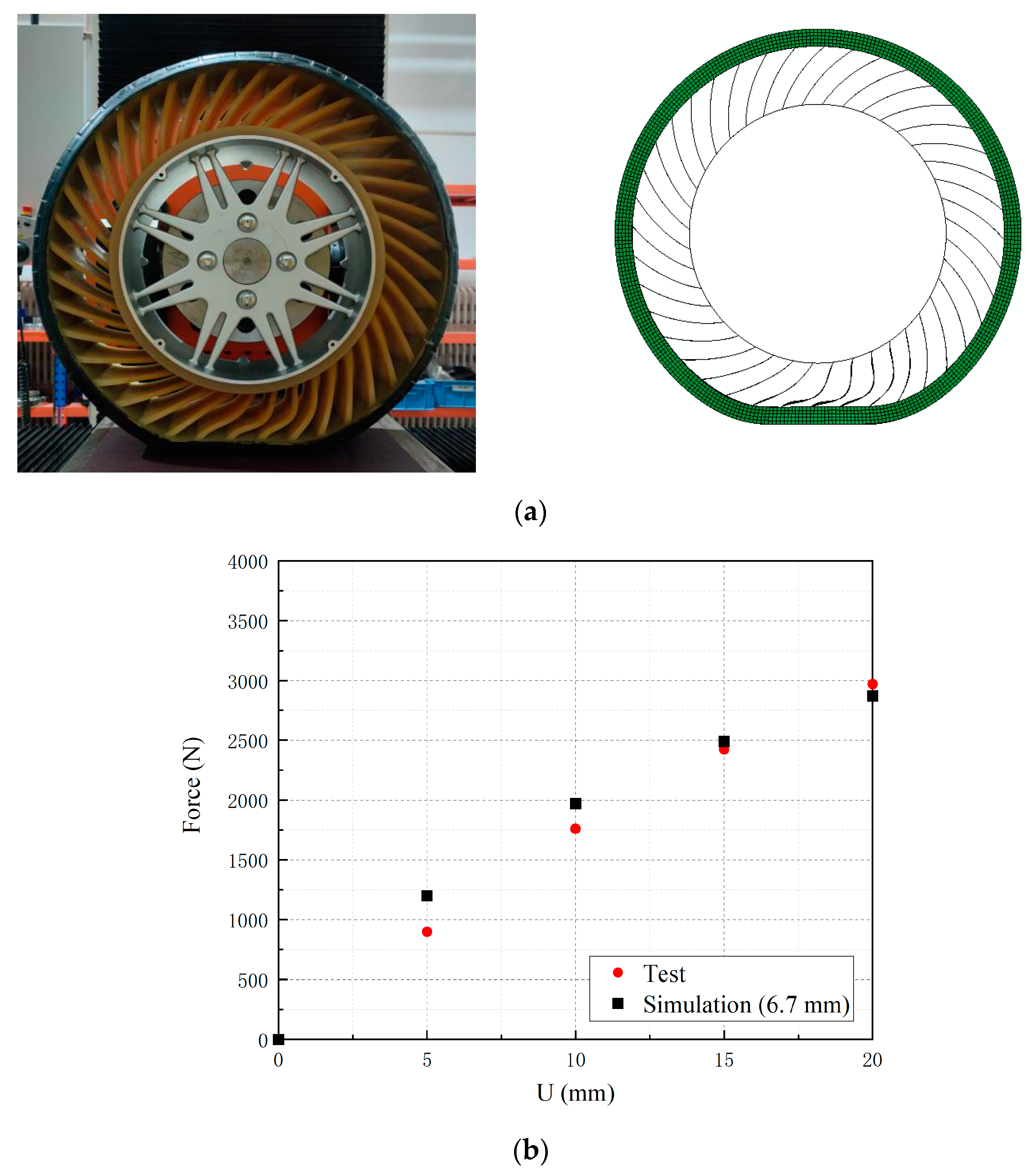
Figure 11a displays the experimental and simulation results of the NPT deformation, and Figure 11b displays the force-displacement curves for the test and simulation. The simulation curve is basically consistent with that of the test. The NPT FE model can be applied to the following optimization process.

4. Thickness Optimization

The object was to minimize the spoke mass. When the deformation of the tire is close to 20 mm, the reaction force reaches 3600 N (the specification of a vehicle Chery eQ1 tire is 165/65 R15, its radial deformation is 20 mm, and the corresponding rated load is 360 kg).
Theoretically, the higher the thickness variable is set, the better the optimal solution obtained. We regarded the number of the radial and axial meshes of the spokes as the number of thickness variables. In order to balance the contradiction between the computational cost and optimization effect, we set the grid size to 1 mm. Thus, there were 26 and 30 design variables for the thickness in the radial and width directions of the tire, respectively. The spoke with 7.5 mm and a 3600 N reaction force was selected to be the initial model, and the total mass of all the spokes was 4.70 kg. The thickness was limited to a range from 4 mm to 10 mm.

4.1. Thickness Optimization in Tire Radial Direction

After 130 generations of iterations, it can in Figure 12 that the maximum thickness is 8.8 mm, and the minimum thickness is 4.0 mm. The thicker regions focus on the middle of the spoke in the tire radial direction. As shown in Figure 13, the reaction force converges to around 3600 N, and the mass of the spoke is reduced by 9%. The final total mass of all the spokes is 4.28 kg.

4.2. Thickness Optimization in Tire-Width Direction

As shown in Figure 14, the thicker regions are located in the middle and at both sides of the spoke in the direction of the tire width. It can be seen that the maximum thickness is 10 mm, and the minimum thickness is 4.0 mm.
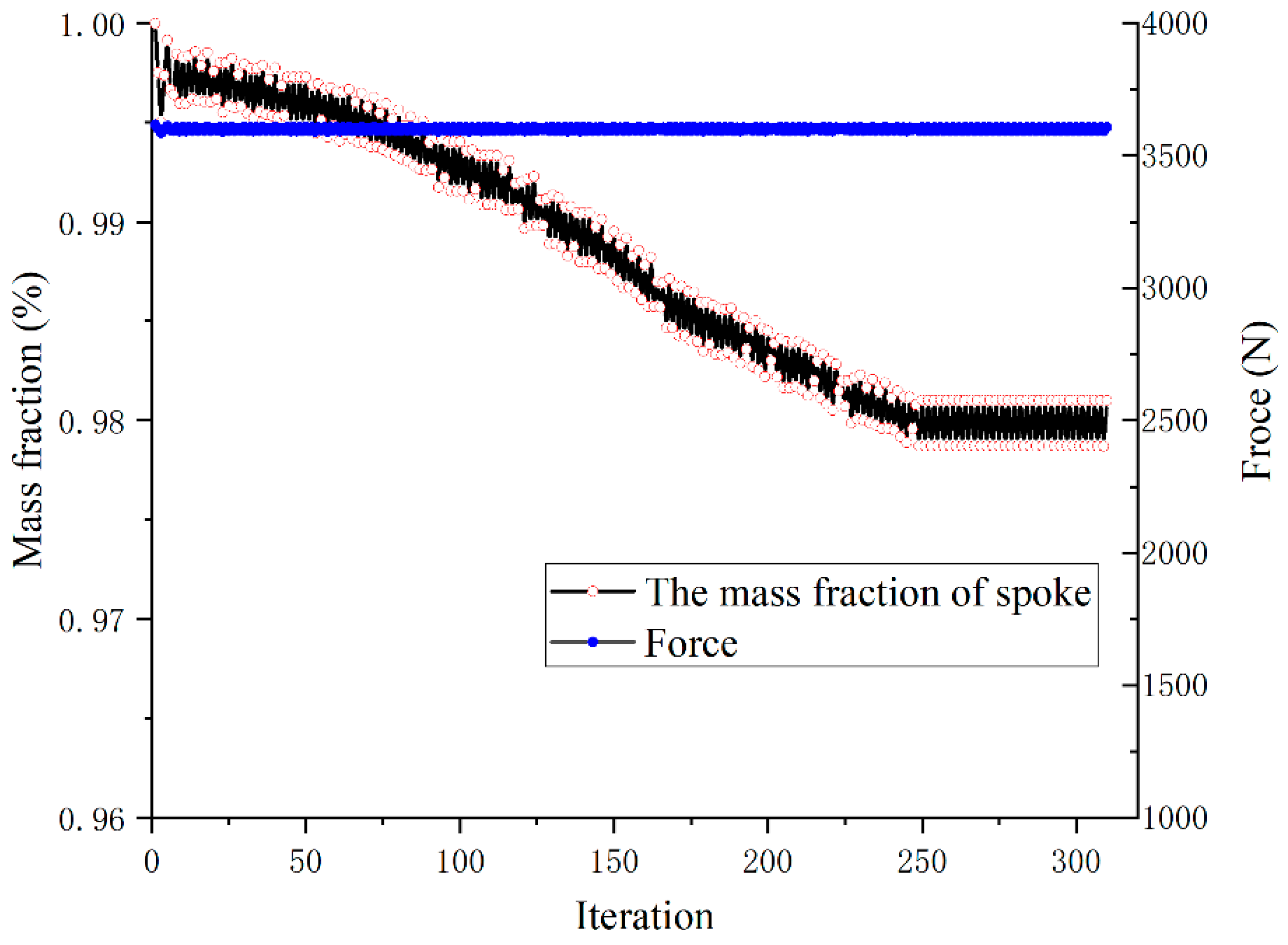
Figure 15 shows that the optimized iterations for the spoke thickness are in the direction of the tire width. After 300 optimization calculations, the mass of the spoke was reduced by only 2% with the force = 3600 N constraint.

4.3. Experimental Validation for Optimized Spoke

The spoke with the variable thickness of the tire radial direction was selected and applied to the test. From Figure 16, it can be seen that the deformation of the spoke was consistent in both the test and simulation. For the same displacement constraint, the radial forces for the test and simulation had good consistency.

5. Conclusions

In this paper, we propose an optimization algorithm for the thickness distribution in the hyperelasticity problem with the force constraint. In Section 2, we establish the functional relationship between the thickness design variables and the target, and we present the thickness-sensitivity analysis. The thickness-sensitivity-constraint method and sensitivity-filtering method are proposed to ensure manufacturability. Section 3 describes how the FE model of the tire was built and validated with the radial-stiffness test. In Section 4, the proposed optimization method is adopted in the tire-mass-minimization problem. The optimized results show that the spoke with variable thicknesses in the tire radial direction can reduced the weight by 9% and met the radial-stiffness requirements. The spoke with variable thicknesses in the tire-width direction reduced the weight by 2% and met the radial-stiffness requirements. Then, the optimized tire was manufactured, and the stiffness test was carried out. The simulation results of the test and optimization are consistent. In summary, the thickness-optimization method that we propose can effectively realize lightweight NPTs.
Through the joint operation of MATLAB and ABAQUS, we realized the lightweight design of variable-thickness spokes of NPTs. At present, this method has certain limitations. It can only reduce the discontinuity of the thickness of the adjacent elements by increasing the number of thickness design variables and filtering. However, the discontinuity of the thickness of the adjacent elements has not been eliminated. In planned follow-up work, we intend to establish the relationship between the nodes of the shell element and thickness, and we will take the nodes of the shell element as the carrier of the thickness variable so as to eliminate the thickness discontinuity of the adjacent elements.

Author Contributions

Conceptualization, T.X. and J.Y.; methodology, J.Y.; software, J.Y. and F.G.; validation, T.X., J.Y. and L.Z.; formal analysis, J.Y.; investigation, J.Y.; resources, T.X.; data curation, J.Y.; writing—original draft preparation, J.Y.; writing—review and editing, T.X. and F.G.; visualization, J.Y.; supervision, T.X.; project administration, T.X.; funding acquisition, T.X. All authors have read and agreed to the published version of the manuscript.

Funding

This research was funded by the Research and development of energy-saving and environment-friendly high-performance non-pneumatic tire, grant number X220091TL220.

Institutional Review Board Statement

Not applicable.

Informed Consent Statement

Not applicable.

Data Availability Statement

Data available upon request from the authors.

Conflicts of Interest

The authors declare no conflict of interest.

References

  1. Zhang, Z.Z.; Lv, J.G.; Song, B.; Guo, S.Y.; Gao, F. Development of non-pneumatic tire technology. In Applied Mechanics and Materials; Trans Tech Publications Ltd.: Wollerau, Switzerland, 2013; Volume 427, pp. 191–194. [Google Scholar] [CrossRef]
  2. Bras, B.; Cobert, A. Life-cycle environmental impact of Michelin Tweel® tire for passenger vehicles. SAE Inte. J. Passeng. Cars-Mech. Syst. 2011, 4, 32–43. [Google Scholar] [CrossRef]
  3. Rhyne, T.B.; Thompson, R.H.; Cron, S.M.; DeMino, K.W. Non-Pneumatic Tire. U.S. Patent 7,201,194, 10 April 2007. [Google Scholar]
  4. Manesh, A.; Tercha, M.; Anderson, B.; Meliska, B.J.; Ceranski, F. Tension-Based Non-Pneumatic Tire. U.S. Patent 8,109,308, 7 February 2012. [Google Scholar]
  5. Manesh, A.; Tercha, M.J.; Meliska, B.; Ceranski, F.; Howland, G.; Stark, L.; Hauch, K.; Petersen, T. Tension-Based Non-Pneumatic Tire. U.S. Patent 8,176,957, 15 May 2012. [Google Scholar]
  6. Mun, D.Y.; Kim, H.J.; Choi, S.J. Non-Pneumatic Tire. EP Patent EP2428369, 14 March 2012. [Google Scholar]
  7. Kim, Y.-H. Non-Pneumatic Tire Having Improved Riding Comfort. CN Patent 105,365,478 A, 2 March 2016. [Google Scholar]
  8. Jang, I.G.; Sung, Y.H.; Yoo, E.J.; Kwak, B.M. Pattern design of a non-pneumatic tyre for stiffness using topology optimization. Eng. Optim. 2012, 44, 119–131. [Google Scholar] [CrossRef]
  9. Zhao, Y.; Du, X.; Lin, F.; Wang, Q.; Fu, H. Static stiffness characteristics of a new non-pneumatic tire with different hinge structure and distribution. J. Mech. Sci. Technol. 2018, 32, 3057–3064. [Google Scholar] [CrossRef]
  10. Ganniari-Papageorgiou, E.; Chatzistergos, P.; Wang, X. The influence of the honeycomb design parameters on the mechanical behavior of non-pneumatic tires. Int. J. Appl. Mech. 2020, 12, 2050024. [Google Scholar] [CrossRef]
  11. Zang, L.; Wang, X.; Yan, P.; Zhao, Z. Structural design and characteristics of a non-pneumatic tire with honeycomb structure. Mech. Adv. Mater. Struct. 2021, 1–8. [Google Scholar] [CrossRef]
  12. Zhang, Z.; Fu, H.; Zhao, Q.; Tan, D.; Yang, K. Pattern design and performance analysis of a flexible spoke bionic non-pneumatic tire. J. Braz. Soc. Mech. Sci. Eng. 2021, 43, 41. [Google Scholar] [CrossRef]
  13. Wu, T.; Li, M.; Zhu, X.; Lu, X. Research on non-pneumatic tire with gradient anti-tetrachiral structures. Mech. Adv. Mater. Struct. 2021, 28, 2351–2359. [Google Scholar] [CrossRef]
  14. Lux, F.; Stumpf, H. Light-Weight Tire Concept. Tire Sci. Technol. 1996, 24, 119–131. [Google Scholar] [CrossRef]
  15. Yang, R.J.; Fu, Y.; Li, G. Application of Tailor Rolled Blank in Vehicle Front End for Frontal Impact (No. 2007-01-0675); SAE Technical Paper; SAE: Evanston, IL, USA, 2007. [Google Scholar] [CrossRef]
  16. Liu, X.H. Prospects for variable gauge rolling: Technology, theory and application. J. Iron Steel Res. Int. 2011, 18, 1–7. [Google Scholar] [CrossRef]
  17. Merklein, M.; Johannes, M.; Lechner, M.; Kuppert, A. A review on tailored blanks—Production, applications and evaluation. J. Mater. Process. Technol. 2014, 214, 151–164. [Google Scholar] [CrossRef]
  18. An, X.; Gao, Y.; Fang, J.; Sun, G.; Li, Q. Crashworthiness design for foam-filled thin-walled structures with functionally lateral graded thickness sheets. Thin-Walled Struct. 2015, 91, 63–71. [Google Scholar] [CrossRef]
  19. Yu, L.; Gu, X.; Qian, L.; Jiang, P.; Wang, W.; Yu, M. Application of tailor rolled blanks in optimum design of pure electric vehicle crashworthiness and lightweight. Thin-Walled Struct. 2021, 161, 107410. [Google Scholar] [CrossRef]
  20. Cheng, W.; Zhang, H.; Fu, S.; Xie, H.; Tang, Z.; Zhu, Z. A process-performance coupled design method for hot-stamped tailor rolled blank structure. Thin-Walled Struct. 2019, 140, 132–143. [Google Scholar] [CrossRef]
  21. Duan, L.; Xiao, N.C.; Li, G.; Cheng, A.; Chen, T. Design optimization of tailor-rolled blank thin-walled structures based on-support vector regression technique and genetic algorithm. Eng. Optim. 2017, 49, 1148–1165. [Google Scholar] [CrossRef]
  22. Gao, D.; Li, X.; Chen, H. Application of improved particle swarm optimization in vehicle crashworthiness. Math. Probl. Eng. 2019, 2019, 8164609. [Google Scholar] [CrossRef] [Green Version]
  23. Lu, R.; Gao, W.; Hu, X.; Liu, W.; Li, Y.; Liu, X. Crushing analysis and crashworthiness optimization of tailor rolled tubes with variation of thickness and material properties. Int. J. Mech. Sci. 2018, 136, 67–84. [Google Scholar] [CrossRef]
  24. Yang, J.; Zhang, S. Crashworthiness Design of Bumper Beam Structure with Tailor Rolled Using Nonlinear Topology Optimization Method. China Mech. Eng. 2017, 28, 2109. [Google Scholar]
  25. Duan, L.; Jiang, H.; Li, H.; Xiao, N. Crashworthiness optimization of VRB thin-walled structures under manufacturing constraints by the eHCA-VRB algorithm. Appl. Math. Model. 2020, 80, 126–150. [Google Scholar] [CrossRef]
  26. Shi, D.; Watanabe, K.; Naito, J.; Funada, K.; Yasui, K. Design optimization and application of hot-stamped B pillar with local patchwork blanks. Thin-Walled Struct. 2022, 170, 108523. [Google Scholar] [CrossRef]
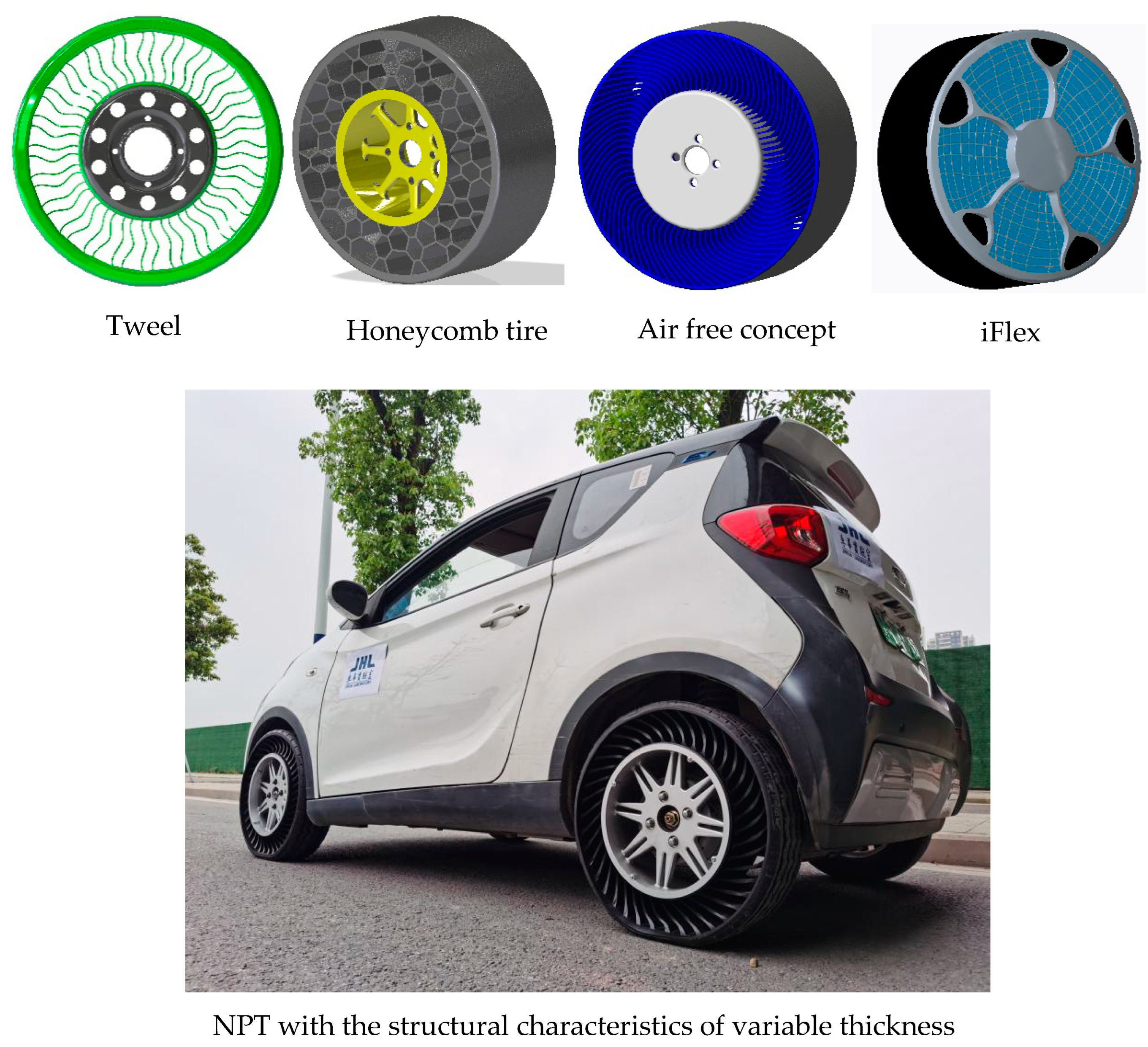
Figure 1. Nonpneumatic tires.
Machines 10 00889 g001
Figure 2. Radial-force comparison of three types of tires.
Machines 10 00889 g002
Figure 3. Radial-force-displacement of tire.
Machines 10 00889 g003
Figure 4. Thickness-variation constraint.
Machines 10 00889 g004
Figure 5. Thickness-sensitivity constraint.
Machines 10 00889 g005
Figure 6. Flowchart of proposed variable-thickness algorithm.
Machines 10 00889 g006
Figure 7. The geometry of the NPT: (a) geometric dimensions of the NPT; (b) geometric dimensions of the spoke.
Machines 10 00889 g007
Figure 8. Forming of spoke.
Machines 10 00889 g008
Figure 9. Stress–strain curves of spoke material.
Machines 10 00889 g009
Figure 10. Finite-element model of the uniform-thickness NPT.
Machines 10 00889 g010
Figure 11. The experimental and simulation results of the NPT: (a) deformation of the test and simulation for the uniform-thickness NPT; (b) force-displacement of the test and simulation for the uniform-thickness NPT.
Machines 10 00889 g011
Figure 12. Optimized thickness distribution for tire-radius direction.
Machines 10 00889 g012
Figure 13. Optimized iterations for thickness in tire-radius direction.
Machines 10 00889 g013
Figure 14. Optimized thickness distribution for thickness in tire-width direction.
Machines 10 00889 g014
Figure 15. Optimized iterations for thickness in tire-width direction.
Machines 10 00889 g015
Figure 16. The experimental and simulation results of the radius-direction-optimized NPT: (a) the deformation of the test and simulation for the radius-direction-optimized NPT; (b) force-displacement of the test and simulation for radius-direction-optimized NPT.
Machines 10 00889 g016
Publisher’s Note: MDPI stays neutral with regard to jurisdictional claims in published maps and institutional affiliations.