Article

Comparative Analysis of Current and Voltage THD at Different Grid Powers for Powerful Active Front-End Rectifiers with Preprogrammed PWM

by
Alexander S. Maklakov
1,*,
Tao Jing
2 and
Alexander A. Nikolaev
3
1
Project Activity Center, Scientific Activity Sector, Moscow Polytechnic University, 107023 Moscow, Russia
2
School of Mechanical and Electrical Engineering, China Jiliang University, Hangzhou 310018, China
3
Department of Automated Electric Drives and Mechatronics, Nosov Magnitogorsk State Technical University, 455000 Magnitogorsk, Russia
*
Author to whom correspondence should be addressed.
Machines 2022, 10(12), 1139; https://doi.org/10.3390/machines10121139
Submission received: 28 October 2022 / Revised: 24 November 2022 / Accepted: 26 November 2022 / Published: 1 December 2022

Abstract

:
Preprogrammed pulse width modulation (PPWM) techniques are drawing a great deal of interest due to their strong harmonic performance. However, there have not yet been any systematic studies or elaboration of the influence of different grid powers on current and voltage THD using PPWM. Therefore, this article focuses on a comparative analysis of current and voltage THD in a system with a three-phase, three-level active front-end (AFE) at different grid powers by applying PPWM. A six-pulse electric drive power circuit and one laboratory measurement platform were designed and set up to achieve the above goals. The comparative results were calculated up to the 50th (THD50) and 100th (THD100) harmonics against the frequency of the PPWM, ranging between 150 Hz and 750 Hz. The grid power and AFE power ratio was between 30 and 230 under three different AFE-consumed currents. The experimental results were analyzed and compared, and they demonstrated for the first time how the grid power and AFE power ratio with different PPWM patterns can influence current and voltage THD. The research results suggest that it is necessary to review the existing calculation methods for current and voltage THD using modern electric power quality standards. The results presented in this article also provide a reference point for researchers and engineers when considering the electromagnetic compatibility (EMC) of nonlinear consumers in the design of similar circuits.

1. Introduction

The use of power conversion systems based on active front-ends (AFEs) to regenerate power is one of the most efficient power-saving solutions for electric drives and distributed generation systems. Many researchers and engineers around the world are working to improve these systems. The main reasons for the widespread application of AFEs include high efficiency (95–98%), two-way electric power flow control with a set cos (φ), and compliance with international electromagnetic compatibility standards [1,2,3,4].
The limiting current and voltage values of semiconductor power systems allow for the use of two-level AFEs in low- and medium-power applications, usually up to 1 MW. As converted power increases, it is necessary to find new engineering solutions; the development of multilevel converter topologies is the most efficient. Currently, multilevel AFEs help ensure the electromagnetic compatibility of high-power consumers, ranging from tens to hundreds of megawatts. Neutral-point-clamped (NPC) is the most efficient and widely used multilevel topology. It is commonly limited to three levels, so academic publications often refer to NPC converters as three-level converters [5,6,7].
One reason for power quality problems in internal grids can be powerful electric drives with NPC AFE rectifiers. Studies have shown that these occur in cases of low grid power with long cable lines. Consequently, grid current resonance leads to high voltage harmonics at the point of common connection (PCC) of electrical consumers. The authors assessed the power quality in the grid of one metallurgical enterprise at the PCC with a 12 MW AFE electric drive of a rolling stand. A simplified power circuit of the electric drive is illustrated in Figure 1. The main characteristics of the circuit are presented in Table 1.
The experimental results were obtained by recording and subsequently analyzing the instantaneous values and spectrum of grid phase-to-phase voltages (Ugrid). A measuring complex was used based on an ELSPEC G4420 power quality analyzer capable of long-term multichannel recording of the Ugrid with a sampling frequency of 100 kHz. A photograph of the measuring complex is shown in Figure 2. The results presented in Figure 3a show that when the electric drive is switched off from the PCC, the Ugrid does not contain significant high-order harmonics, and the THD is approximately 1%. The experiment proves that the main harmonic source in the power grid is the AFE electric drive of the rolling stand, since when it was connected, the voltage quality deteriorated significantly, as shown in Figure 3b. The harmonics with maximum voltage magnitudes (Mag, %) are numbered n = 23, 107, 109, and 113.
The efficiency of operation and the quality of the converted power of semiconductor converters largely depend on the selection of a specific pulse width modulation (PWM) strategy. The existing preprogrammed PWM (PPWM) method, based on the use of preprogrammed switching patterns for the semiconductor modules of converters, was designed to minimize the losses and increase the quality of the converted power. Researching, developing, and improving PPWM strategies is especially relevant for designing and ensuring the electromagnetic compatibility of three-level AFEs [8,9,10].
This study demonstrates, for the first time, how the ratio of the grid power and the AFEs at various patterns of PPWM with SHE can influence current and voltage THD. This article may shed light on the occurrence of electromagnetic compatibility problems in AFEs when the power system has insufficient power. The article is organized as follows: the Introduction describes the subject, explains the relevance of the study, and formulates its goals and objectives; Section 2 describes PPWM algorithms; Section 3 describes the experimental facilities; Section 4 analyzes the modeling results; and Section 5 gives the conclusion.

2. PPWM

2.1. Overview

Since the 1990s, there have been several trends in the development of the PPWM method that aim to resolve the research and engineering issues related to electromagnetic compatibility, energy efficiency, and increasing the power output of AFEs based on multilevel converter topologies [11,12,13]. When PPWM appeared, it attracted a lot of attention from experts in power conversion equipment all around the world. This method was also adapted to numerous application areas, mainly for high-voltage and high-power AFEs, where ensuring electromagnetic compatibility and switching losses are significant problems, and their resolution is a priority. PPWM demonstrates the following advantages [14,15,16]:
(1)
Increased efficiency and quality parameters of the converted voltage;
(2)
Increased effective converter voltage value;
(3)
Reduced requirements for the filtering of feedback signals for converter currents and voltages;
(4)
The opportunity to bypass the current and voltage resonance region without additional filter-compensating equipment;
(5)
The opportunity to leave the harmonics that are divisible by three in the three-phase converter voltage system uncontrolled;
(6)
The opportunity to control the levels of specific harmonic components and the total index of harmonic distortions of voltage/current.
The mathematical expression of the modulated converter voltage signal function u (ωt) for PPWM is based on Fourier-series decomposition and calculation of switching angles α that help eliminate/control selected low-order harmonics. The general-case expression for u (ωt) can be written as follows:
u ( ω t ) = a 0 2 + n = 1 ( a n cos ( n ω t ) + b n sin ( n ω t ) )
where ω is the angular frequency, n is the number of harmonics, and a0, an, and bn are the Fourier-series coefficients:
a 0 = 1 π 0 2 π u ( ω t ) d ( ω t ) , a n = 1 π 0 2 π u ( ω t ) cos ( n ω t ) d ( ω t ) , b n = 1 π 0 2 π u ( ω t ) sin ( n ω t ) d ( ω t ) .
The most widespread waveform of converter voltage features quarter-wave symmetry. This form significantly simplifies Equation (1) [17]. Constant a0 represents even harmonics, and sinusoidal coefficients of fuzzy harmonics equal zero, which transforms Equation (1) for a three-level signal waveform as follows:
u ( ω t ) = n = 1 , 3 , 5 , ( 4 n π [ k = 1 N ( 1 ) k + 1 cos ( n α k ) ] sin ( n ω t ) )
where N is the number of switchings, and k is the sequence number of the switching angle from 1 to N.
The typical waveform of a three-level signal with quarter-wave symmetry is shown in Figure 4. The switching angles within the quarter period should keep the following ratios:
0 < α 1 < α 2 < < α N < π / 2
Academic publications suggest several approaches to signal spectrum formation using PPWM. All are based on searching for switching angles α using a specific optimality criterion. These may be classified as follows:
(1)
Selective harmonic elimination (SHE);
(2)
Selective harmonic mitigation (SHM).

2.2. Selective Harmonic Elimination

SHE is the most widespread approach to implementing the PPWM algorithm. It was first demonstrated in 1973 for a two-level AFE to eliminate some low-order harmonics in the AFE voltage spectrum. The implementation of this approach can be exemplified by the voltage waveform of a three-level converter with quarter-wave symmetry, as shown in Figure 4 [18]. This waveform is set by the switching pattern of the AFE semiconductor modules at predetermined moments using the precalculated switching angles α 1 , α 2 , , α N , numbered N, over a quarter AFE voltage period that ranges between 0 and π/2, provided that 0 < α 1 < α 2 < < α N < π / 2 .
The maximum number of switching angles N may be determined as follows:
N = f s w a v e f
where fswave is the average switching frequency for the AFE semiconductor modules, and f is the AFE voltage frequency.
Due to the quarter-wave symmetry of the signal waveform, only odd sinusoid components bn are left after Fourier transformation:
{ a n = 0 b n = { 0 , 4 n π U d c 2 k = 1 N ( 1 ) k + 1 cos ( n α k ) ,
where Udc is the AFE DC link voltage.
The number of harmonic components that can be equaled to zero in System (6) is limited by the number of semiconductor module switching occurrences and can be calculated using the following formula:
q = N 1
System (6) determines the correlation between the switching angles and the harmonic spectrum of an AFE signal as follows:
{ U 1 = k = 1 N ( 1 ) k + 1 cos ( α k ) = π 4 M U n = 4 π k = 1 N ( 1 ) k + 1 cos ( n α k ) = 0 ,   w h e r e   n = 5 ,     7 ,   11 ,     .
where U1 is the level of the fundamental harmonic, Un is the level of harmonic n, and M is the modulation index between zero and 4 π .
The set of solutions for the system of Equation (8) can be obtained as sequences of switching angles α 1 , α 2 , , α N in the constraint region 0 < α 1 < α 2 < < α N < π / 2 . Then, the most desirable solutions of each one are selected.

2.3. Selective Harmonic Mitigation

SHM was first used in 2007 for a three-level 150 kVA converter. This approach was based on satisfying voltage quality standards, particularly the total harmonic component (THD) coefficient and the levels of specific harmonic components of AFE voltage [19,20,21,22]. The equation defining the correlation between the switching angles and harmonic spectrum of the signal is as follows:
{ | π 4 M U 1 | L 1 1 | U 1 | 4 n π k = 1 N ( 1 ) k + 1 cos ( n α k ) L n ,   w h e r e   n = 5 ,     7 ,   11 ,     ,   49 .
where L1 is the constraint determining the level of the first harmonic, depending on the modulation coefficient, and Ln is the level constraint for every harmonic component n.
The sets of switching angles α 1 , α 2 , , α N are in the constraint region 0 < α 1 < α 2 < < α N < π / 2 . SHM allows for the identification of the switching angle sequence for the AFE semiconductor modules within the set constraints Ln corresponding to electric power quality standards.
The system of nonlinear equations describing the waveform of PPWM with SHE components can be solved using an array of mathematical methods. Current research concerning PPWM techniques is focused on mathematical algorithms to find new patterns [23,24,25,26,27,28,29,30,31,32,33]. During this research, the authors tested several of them, but the best results were produced using built-in functions of MATLAB software, namely fsolve and fmincon. Some PWM sequences were calculated and notated with the following codes: SHE3, SHE5, SHE7, SHE9, SHE11, SHE13, SHE15, SHM13, and SHM15.

3. Experiments

The research was carried out in a power conversion equipment laboratory. A generalized diagram of the test bench’s hardware and software setup is shown in Figure 5. The specifications of the laboratory prototype and the testing system are presented in Table 2.
Direct access to the control signal of the semiconductor modules was gained through optic-fiber inputs. Then, the galvanically isolated voltage probes of the DC and AC links at the converter input were connected to analog outputs. Overvoltage, overcurrent, and overheating protection were built into each converter’s NPC cells, and the converters were programmed by the researchers using a built-in microcontroller and a complex programmable logic device (CPLD). The mezzanine module was designed to transmit signals from optic inputs and analog outputs between the CPLD and the BoomBox control platform, including the digital signal processor (DSP) and the field programmable gate array (FPGA). The converter control tasks were distributed between the DSP and the FPGA. The FPGA controlled the correct distribution of the IGBT control impulses, and the DSP processed the converter control system program. The computing core of the DSP was a 32-bit TMS320C28346 processor manufactured by Texas Instruments with a clock rate of 300 MHz and featuring 256 MB NOR flash memory, 2 MB RAM, and 300 MIPS (with a floating point). The program code for the control platform was developed in MATLAB/Simulink. To take an oscillogram and measure the instant voltage values at the three-level converter input, we used the WindowsTM-based graphic software of the BoomBox control platform. We measured voltage signals using ModuLink isolated voltage probes for the range of ± 800 V with a bandpass of 60 kHz and a response of 2.46 mV/V. The probes were connected to the BoomBox control platform using the plug-and-play method and powered directly from the control platform. The output signal was transmitted over a screened twisted pair of probes integrated into RJ45 cables. Additional verification of the obtained oscillograms was carried out using a Tektronix TBS2072 oscilloscope with a bandpass of 80 MHz and a sampling frequency of 1 GSa/s, in addition to a differential HVP-08 sampler model.
Most AFE control systems are based on so-called voltage-oriented control (VOC). Linear controllers are either proportional (P) or proportional–integral (PI). Figure 6 depicts the circuit diagram of the AFE closed-loop control system used in the objective analysis. One special feature of this circuit is that the three-phase current signals iabc and the three-phase voltage signals uabc are measured at the primary side of the phase-shift transformer (T). This is possible since there are no other power-consuming devices. Figure 6 uses the following notation: T is the phase-shift transformer; PLL is the unit that synchronizes voltages with the secondary windings of the phase-shift transformer; iabc and uabc are the measured instantaneous phase currents and values on the primary side of the phase-shift transformer in the abc coordinates; θ is the grid voltage space vector angle for the secondary windings of the phase-shift transformer; idq is the measured instantaneous phase currents and values on the primary side of the phase-shift transformer in the dq0 coordinates; idqref is the configured phase current of the AFE in the dq0 coordinates; udq is the measured instantaneous phase voltage of the AFE in the dq0 coordinates; udc is the measured instantaneous voltage of the DC link capacitors in the AFE; udcref is the configured AFE DC link capacitor voltages; M is the AFE modulation index; α’ is the phase shift between the secondary windings of the phase-shift transformer and the phase voltage of the AFE; LAFE is the AFE input inductance; Rload is the load resistance; LPF is the lowpass filter; SPG is the switching pattern generator, which can generate the SHE/SHM switching pattern {SSHE/SHM} based on θ, M, and α’. This experiment did not analyze the synthesis of the current and voltage control system. Controllers were synthesized using cascade control. To provide the stability and accuracy of a closed-loop system, it was necessary to consistently monitor that the values θ, M, and α’ were constant during the operation of the system since the output accuracy of the SHE/SHM switching pattern {SSHE/SHM} through a switching pattern generator (SPG) can only be ensured this way. Only accurate SHE/SHM waveforms can ensure that the output results meet the system requirements. Therefore, an LPF was used to filter noise from the circuit, and the parameters of the PI controllers for the DC link voltage and current were carefully designed. Figure 7 shows the oscillograms of the instant AFE voltage values at a modulation index of 1.05. All oscillograms complied with the precalculated switching patterns.

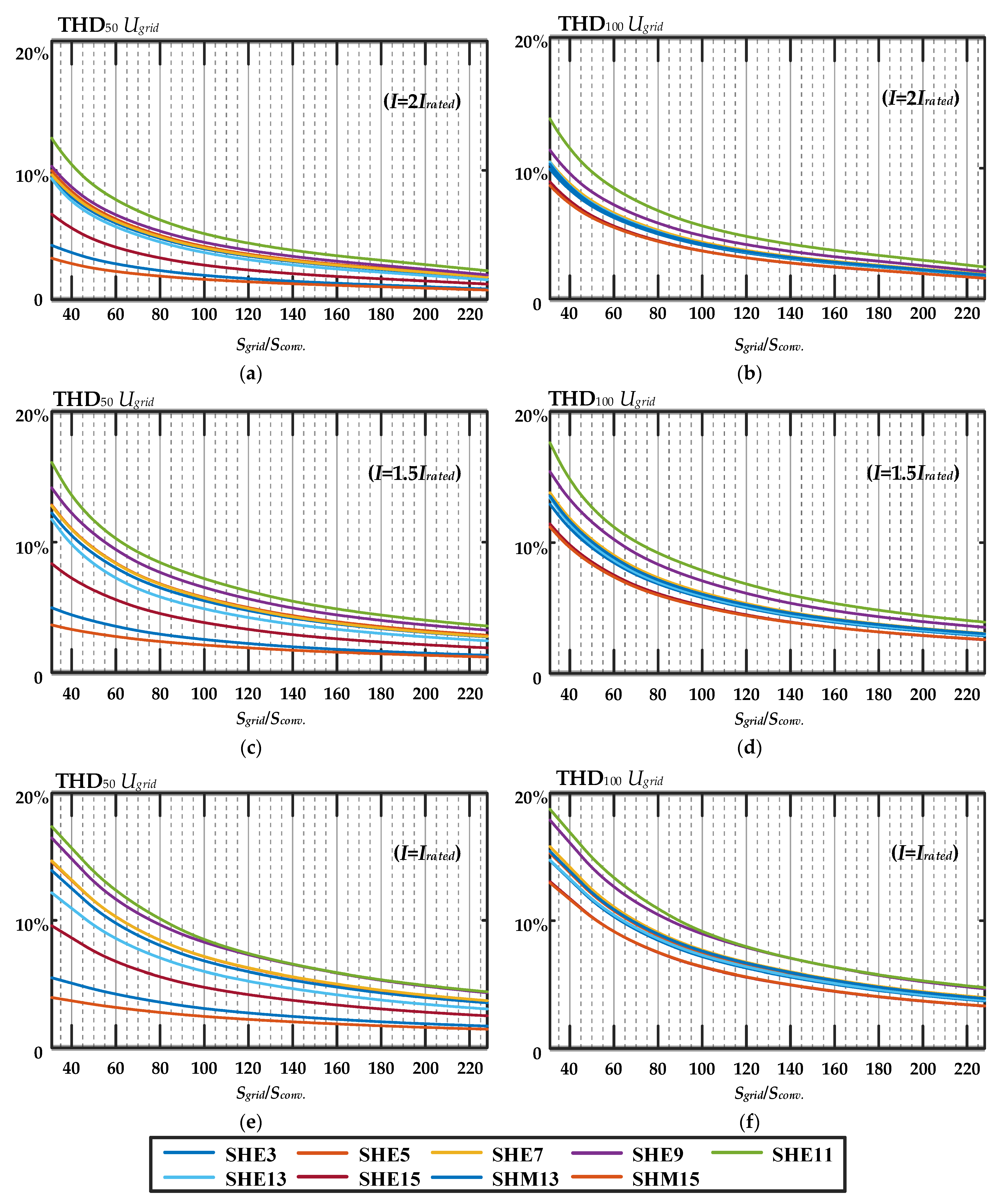
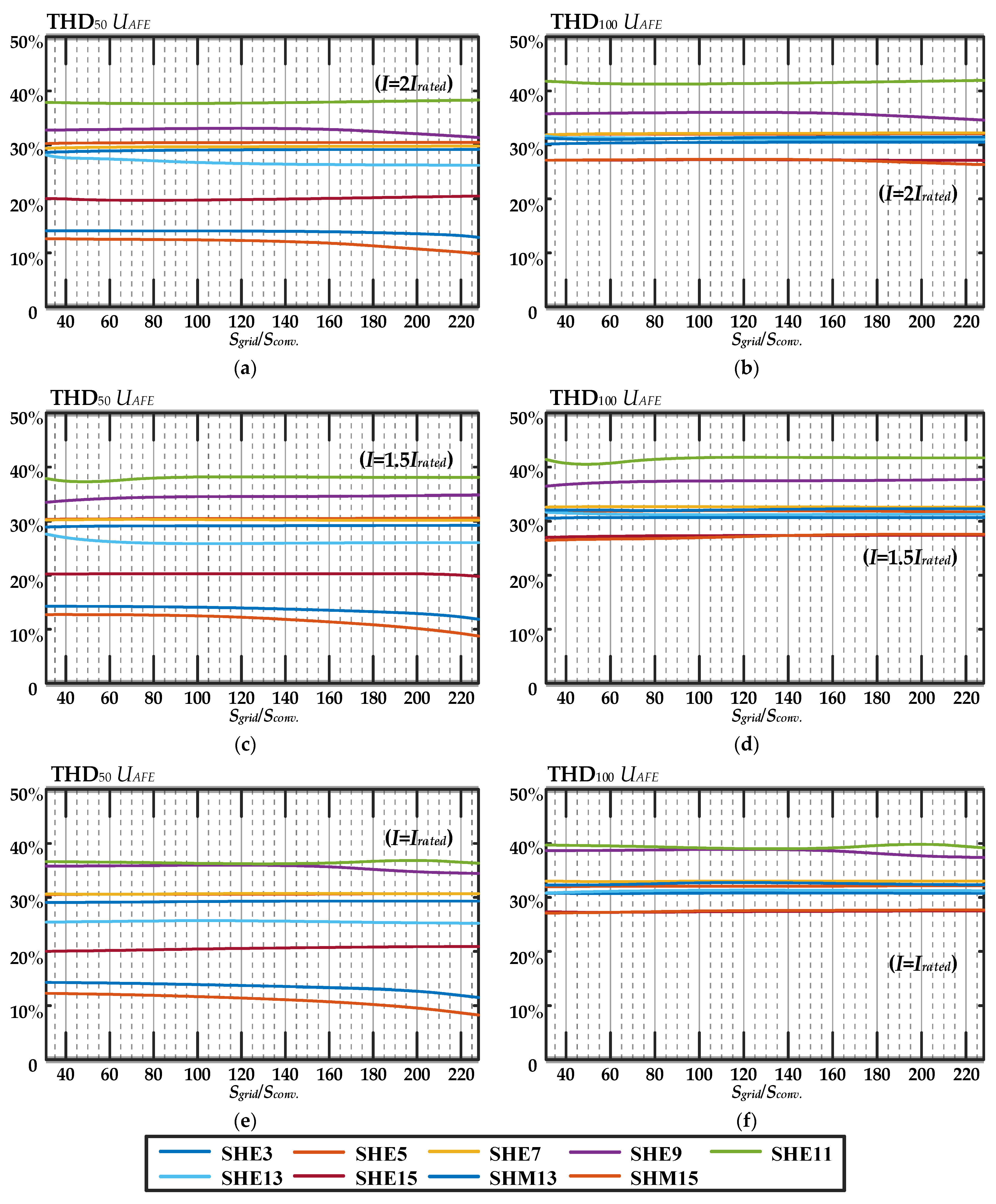
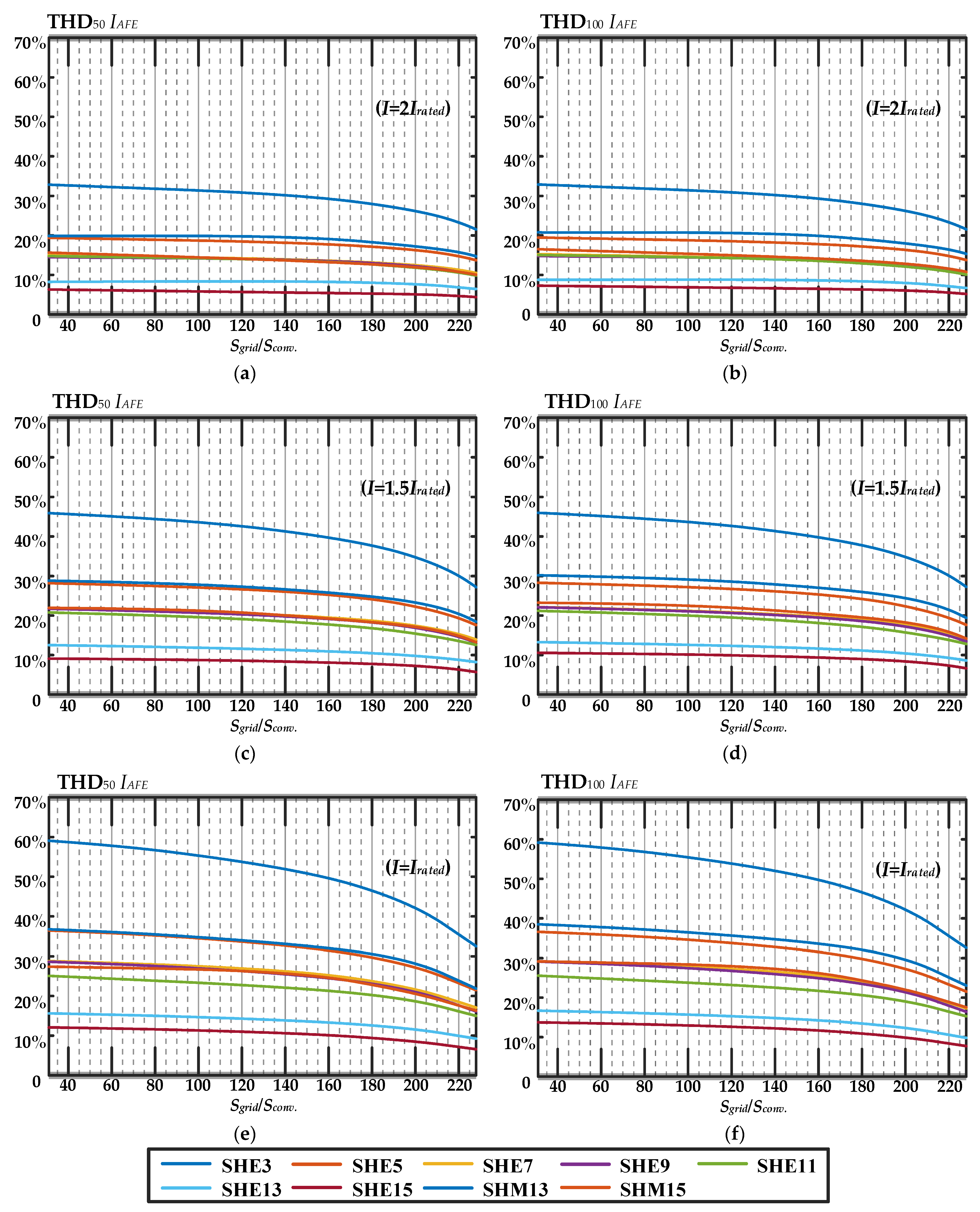
4. Experimental Research Analysis

The impact of a three-level AFE featuring PPWM with SHE on current and voltage THD was studied at various ratios of AFE power Sconv and grid power Sgrid. The range of Sgrid/Sconv was selected between 30 and 230, accounting only for active inductive reactance. The current and voltage THD numbers were calculated up to the 50th and 100th harmonics for three different consumed AFE current values: I = Irated, I = 1.5 Irated, and I = 2 Irated. All of the obtained dependencies for SHE3, SHE5, SHE7, SHE9, SHE11, SHE13, SHE15, SHM13, and SHM15 were rendered as graphs and are shown in Figure 8, Figure 9 and Figure 10. Analysis of the results led to the following findings.
Figure 8 shows that the THD of grid voltage Ugrid had the greatest distortion at I = Irated for both THD50 Ugrid and THD100 Ugrid. This can be explained by the reduction in the AFE modulation coefficients due to the reduction in the consumed current, which led to deterioration of the AFE voltage signal spectrum. As the consumed current increased from I = Irated to I = 2 Irated, there was a downward trend for THD50 Ugrid and THD100 Ugrid. As expected, as the Sgrid/Sconv ratio increased, THD50 Ugrid and THD100 Ugrid gradually decreased. Note that the rate of this downward trend varied across different Sgrid/Sconv ranges, i.e., THD50 Ugrid and THD100 Ugrid decreased several times when Sgrid/Sconv was between 30 and 120, while the reduction was less noticeable when Sgrid/Sconv was between 120 and 230. If we compare THD50 Ugrid and THD100 Ugrid, we can see significant differences for all dependencies within the Sgrid/Sconv range from 30 to 120, especially for SHM13 and SHM15. Furthermore, we can see that THD50 Ugrid was significantly lower than THD100 Ugrid (5–7 times lower in some cases). This was because the eliminated or mitigated harmonics were located in the PPWM spectrum below the 50th harmonic component. More importantly, if we follow THD100 Ugrid, it approaches the same value in all calculated dependencies.
Figure 9 shows that the AFE voltage for both THD50 UAFE and THD100 UAFE did not change significantly when the current increased from I = Irated to I = 2Irated or when Sgrid/Sconv changed. This is because the AFE voltage mainly depends on the PPWM algorithm and reliable control system operation. If we compare THD50 UAFE and THD100 UAFE, significant differences for SHM13 and SHM15 are observed. At the same time, the values of THD50 UAFE differed for each of the calculated patterns. Thus, the positive impact of the increasing AFE switching rate on voltage quality is apparent. However, if we analyze THD100 UAFE, the differences are not as significant, and sometimes there are no differences.
Figure 10 shows the current consumed by the AFE, IAFE. The THD of the AFE current, IAFE, had the greatest distortion, with I = Irated for both THD50 IAFE and THD100 IAFE. This can be explained by the reduction in the AFE modulation coefficients due to the reduction in the consumed current, which led to deterioration of the AFE voltage signal spectrum. As the consumed current increased from I = Irated to I = 2 Irated, there was a downward trend for THD50 IAFE and THD100 IAFE. It should be noted that in all experiments, THD50 IAFE and THD100 IAFE had the same or virtually the same values. This is because within the spectrum of the AFE current, IAFE, harmonics up to the 50th order had some impact, while the rest were mitigated by the inductive reactance of the grid. It should be noted that as the Sgrid/Sconv ratio increased, THD50 IAFE and THD100 IAFE gradually decreased. The reduction rate was insignificant, and it differed notably from the grid voltage, as illustrated in Figure 8.

5. Conclusions

This article provides a comparative analysis of current and voltage THD in a circuit featuring a three-phase, three-level AFE with various switching patterns of PPWM and grid power. The experiments were conducted in a power conversion equipment laboratory. The results of the current and voltage THD comparison were calculated up to the 50th and 100th harmonics against the frequency of PPWM, with SHE ranging between 150 Hz and 750 Hz and the grid and the AFE power ratio between 30 and 230 under three different AFE-consumed currents.
This study demonstrates, for the first time, how the grid and AFE power ratio with different PPWM patterns can influence current and voltage THD. We observed that THD100 grid voltage approached the same value with all of the calculated PPWM patterns. Moreover, it was demonstrated that, as the PPWM switching frequency increased, the THD50 of the AFE voltage decreased significantly, but the THD100 analysis showed that the differences were not greatly significant and were sometimes absent. When high-power AFE rectifiers were used, it was reasonable to calculate THD to the 100th harmonic. This allows for a more accurate assessment of the AFE’s electromagnetic compatibility compliance with the grid.
The research results suggest that it is necessary to review the existing calculation methods for current and voltage THD using modern electric power quality standards. In addition, the results also provide a reference point for researchers and engineers to consider the electromagnetic compatibility (EMC) of nonlinear consumers in the design of similar circuits.

Author Contributions

Conceptualization, A.S.M.; methodology, A.A.N. and A.S.M.; software, T.J. and A.S.M.; validation, A.A.N.; formal analysis, T.J.; investigation, T.J. and A.S.M.; resources, A.A.N. and A.S.M.; data curation, A.A.N.; writing—original draft preparation, A.S.M.; writing—review and editing, A.A.N. and T.J.; visualization, T.J.; supervision, A.S.M.; project administration, A.S.M. All authors have read and agreed to the published version of the manuscript.

Funding

This study was financially supported by the Moscow Polytechnic University (Pyotr Kapitsa grant).

Institutional Review Board Statement

Not applicable.

Informed Consent Statement

Not applicable.

Data Availability Statement

Not applicable.

Conflicts of Interest

The authors declare no conflict of interest.

Nomenclature

THDTotal harmonic distortion
AFEActive front-end
PPWMPreprogrammed pulse width modulation
NPCNeutral-point-clamped
DCDirect current
SHESelective harmonic elimination
SHE35th and 7th harmonic elimination
SHE55th, 7th, 11th, and 13th harmonic elimination
SHE75th, 7th, 11th, 13th, 17th, and 19th harmonic elimination
SHE95th, 7th, 11th, 13th, 17th, 19th, 23rd, and 25th harmonic elimination
SHE115th, 7th, 11th, 13th, 17th, 19th, 23rd, 25th, 29th, and 31st harmonic elimination
SHE135th, 7th, 11th, 13th, 17th, 19th, 23rd, 25th, 29th, 31st, 35th, and 37th harmonic elimination
SHE155th, 7th, 11th, 13th, 17th, 19th, 23rd, 25th, 29th, 31st, 35th, 37th, 41st, and 43rd harmonic elimination
SHMSelective harmonic mitigation
SHM135th, 7th, 11th, 13th, 17th, 19th, 23rd, 25th, 29th, 31st, 35th, 37th, 41st, 43rd, 47th, and 49th harmonic mitigation
SHM155th, 7th, 11th, 13th, 17th, 19th, 23rd, 25th, 29th, 31st, 35th, 37th, 41st, 43rd, 47th, and 49th harmonic mitigation
VOCVoltage-oriented control
PLLPhase-locked loop
LPFLow-pass filter
SPGSwitching pattern generator
CPLDComplex programmable logic device
FPGAField-programmable gate array
DSPDigital signal processor
TTransformer
IGBTInsulated-gate bipolar transistor
MIPSMillion instructions per second
SconvConverter power
SgridGrid power
IratedRated AFE-consumed current
UgridPhase-to-phase grid voltage
UAFEPhase-to-phase AFE voltage

References

  1. Leon, J.I.; Vazquez, S.; Franquelo, L.G. Multilevel converters: Control and modulation techniques for their operation and industrial applications. Proc. IEEE 2017, 105, 2066–2081. [Google Scholar] [CrossRef]
  2. Abu-Rub, H.; Bayhan, S.; Moinoddin, S.; Malinowski, M.; Guzinski, J. Medium-Voltage Drives: Challenges and existing technology. IEEE Power Electron. Mag. 2016, 3, 29–41. [Google Scholar] [CrossRef]
  3. Cheng, J.; Xu, T.; Chen, D.; Chen, G. Dynamic and steady state response analysis of selective harmonic elimination in high power inverters. IEEE Access 2021, 9, 75588–75598. [Google Scholar] [CrossRef]
  4. Hoevenaars, A.; Farbis, M.; McGraw, M. Active harmonic mitigation: What the manufacturers don’t tell you. IEEE Ind. Appl. Mag. 2020, 62, 41–51. [Google Scholar] [CrossRef]
  5. Chen, J.; Shen, Y.; Chen, J.; Bai, H.; Gong, C.; Wang, F. Evaluation on the Autoconfigured Multipulse AC/DC Rectifiers and Their Application in More Electric Aircrafts. IEEE Trans. Transp. Electrif. 2020, 6, 1721–1739. [Google Scholar] [CrossRef]
  6. Patil, S.D.; Kadu, A.; Dhabe, P. Improved Control Strategy for Harmonic Mitigation in Multilevel Inverter. In Proceedings of the 5th International Conference on Intelligent Computing and Control Systems, Madurai, India, 6–8 May 2021; pp. 727–732. [Google Scholar]
  7. Steczek, M.; Chudzik, P.; Szeląg, A. Combination of SHE- and SHM-PWM techniques for VSI DC-link current harmonics control in railway applications. IEEE Trans. Ind. Electron. 2017, 64, 7666–7678. [Google Scholar] [CrossRef]
  8. Nikolaev, A.A.; Gilemov, I.G.; Denisevich, A.S. Analysis of Influence of Frequency Converters with Active Rectifiers on the Power Quality in Internal Power Supply Systems of Industrial Enterprises. In Proceedings of the International Conference on Industrial Engineering, Applications and Manufacturing, Moscow, Russia, 1–4 May 2018. [Google Scholar]
  9. Portillo, R.; Sharifzadeh, M.; Vahedi, H.; Franquelo, L.G.; Al-Haddad, K. Improved Hybrid SHM-SHE Modulation Technique 865 for Four-Leg Three-Level NPC Inverters. In Proceedings of the IECON 2015-41st Annual Conference of the IEEE Industrial 866 Electronics Society, Yokohama, Japan, 9–12 November 2015. [Google Scholar]
  10. Campos-Gaona, D.; Peña-Alzola, R.; Monroy-Morales, J.L.; Ordonez, M.; Anaya-Lara, O.; Leithead, W.E. Fast selective harmonic mitigation in multifunctional inverters using internal model controllers and synchronous reference frames. IEEE Trans. Ind. Electron. 2017, 64, 6338–6349. [Google Scholar] [CrossRef] [Green Version]
  11. Su, N.; Huang, W.; Zheng, S. Closed-loop dynamic control for dual-stator winding induction generator at low carrier ratio with selective harmonic elimination pulsewidth modulation. IEEE Trans. Ind. Electron. 2020, 68, 4737–4747. [Google Scholar] [CrossRef]
  12. Sharifzadeh, M.; Vahedi, H.; Sheikholeslami, A.; Labbé, P.; Al-Haddad, K. Hybrid SHM–SHE modulation technique for a four-leg NPC inverter with DC capacitor self-voltage balancing. IEEE Trans. Ind. Electron. 2015, 62, 4890–4899. [Google Scholar] [CrossRef]
  13. Janabi, A.; Wang, B.; Czarkowski, D. Generalized Chudnovsky algorithm for real-time PWM selective harmonic elimination/modulation: Two-Level VSI example. IEEE Trans. Power Electron. 2020, 35, 5437–5446. [Google Scholar] [CrossRef]
  14. Marquez Alcaide, A.; Leon, J.I.; Laguna, M.; Gonzalez-Rodriguez, F.; Portillo, R.; Zafra-Ratia, E.; Vazquez, S.; Franquelo, L.G.; Bayhan, S.; Abu-Rub, H. Real-Time Selective Harmonic Mitigation Technique for Power Converters Based on the Exchange Market Algorithm. Energies 2020, 13, 1659. [Google Scholar] [CrossRef] [Green Version]
  15. Moeini, A.; Zhao, H.; Wang, S. A current-reference-based selective harmonic current mitigation PWM technique to improve the performance of cascaded H-bridge multilevel active rectifiers. IEEE Trans. Ind. Electron. 2018, 65, 727–737. [Google Scholar] [CrossRef]
  16. Nikolaev, A.A.; Gilemov, I.G.; Bulanov, M.V.; Kosmatov, V.I. Providing Electromagnetic Compatibility of High-Power Frequency Converters with Active Rectifiers at Internal Power Supply System of Cherepovets Steel Mill. In Proceedings of the International Scientific Technical Conference Alternating Current Electric Drives, Ekaterinburg, Russia, 1–8 May 2021. [Google Scholar]
  17. de Carvalho Alves, M.D.; e Silva Aquino, R.N.A.L. Digital implementation of SHE-PWM modulation on FPGA for a multilevel inverter. In Proceedings of the Simposio Brasileiro de Sistemas Eletricos (SBSE), Niteroi, Brazil, 1–6 May 2018. [Google Scholar] [CrossRef]
  18. Janabi, A.; Wang, B. Real-Time Implementation of Selective Harmonic Elimination with Seamless Dynamic Performance. In Proceedings of the IEEE Energy Conversion Congress and Exposition, Portland, OR, USA, 23–27 September 2018; pp. 3362–3366. [Google Scholar]
  19. Aguilera, R.P.; Acuña, P.; Lezana, P.; Konstantinou, G.; Wu, B.; Bernet, S.; Agelidis, V.G. Selective harmonic elimination model predictive control for multilevel power converters. IEEE Trans. Power Electron. 2017, 32, 2416–2426. [Google Scholar] [CrossRef] [Green Version]
  20. Sharifzadeh, M.; Vahedi, H.; Portillo, R.; Franquelo, L.G.; Al-Haddad, K. Selective harmonic mitigation based self-elimination of triplen harmonics for single-phase five-level inverters. IEEE Trans. Power Electron. 2019, 34, 86–96. [Google Scholar] [CrossRef]
  21. González, F.J.; Marquez, A.; Leon, J.I.; Vazquez, S.; Franquelo, L.G.; Yin, J. Flexible Harmonic Control for Three-Level Selective Harmonic Modulation Using the Exchange Market Algorithm. In Proceedings of the IECON 2018—44th Annual Conference of the IEEE Industrial Electronics Society, Washington, DC, USA, 21–23 October 2018; pp. 5297–5302. [Google Scholar]
  22. Semedyarov, A.; Ruderman, A. Selective Harmonic Mitigation by Time Domain Constrained Optimization. In Proceedings of the 9th IEEE International Symposium on Power Electronics for Distributed Generation Systems, Charlotte, CA, USA, 1–6 June 2018. [Google Scholar]
  23. Buccella, C.; Cimoroni, M.G.; Cecati, C. Simple SHE Formulation for Five-Level Cascaded H-Bridge Inverters. In Proceedings of the IEEE 15th International Conference on Compatibility, Power Electronics and Power Engineering, Florence, Italy, 1–6 July 2021. [Google Scholar]
  24. Buccella, C.; Cimoroni, M.G.; Cecati, C. Selective Harmonic Elimination Modulation for HVDC Modular Multilevel Converter. In Proceedings of the AEIT HVDC International Conference, Genoa, Italy, 1–6 May 2021. [Google Scholar]
  25. Khattak, F.A.; Rehman, H.U. Improved Selective Harmonics Elimination Strategy for Multilevel Inverters with Optimal DC Values. In Proceedings of the International Conference on Emerging Power Technologies, Topi, Pakistan, 1–6 April 2021. [Google Scholar]
  26. Islam, J.; Meraj, S.T.; Masaoud, A.; Mahmud, M.A.; Nazir, A.; Kabir, M.A.; Hossain, M.M.; Mumtaz, F. Opposition-based quantum bat algorithm to eliminate lower-order harmonics of multilevel inverters. IEEE Access 2021, 9, 103610–103626. [Google Scholar] [CrossRef]
  27. Sadoughi, M.; Zakerian, A.; Pourdadashnia, A.; Farhadi-Kangarlu, M. Selective Harmonic Elimination PWM for Cascaded H-bridge Multilevel Inverter with Wide Output Voltage Range Using PSO Algorithm. In Proceedings of the IEEE Texas Power and Energy Conference, College Station, TX, USA, 1–6 February 2021. [Google Scholar]
  28. Aggrawal, H.; Leon, J.I.; Franquelo, L.G.; Kouro, S.; Garg, P.; Rodriguez, J. Innovative Computational Approach to Harmonic Mitigation for Seven-Level Cascaded H-Bridge Inverters. In Proceedings of the IECON 2011—37th Annual Conference of the IEEE Industrial Electronics Society, Melbourne, Australia, 7–10 November 2021; pp. 4424–4432. [Google Scholar]
  29. Ahmad, S.; Iqbal, A.; Ali, M.; Rahman, K.; Ahmed, A.S. A fast convergent homotopy perturbation method for solving selective harmonics elimination PWM problem in multi level inverter. IEEE Access 2021, 9, 113040–113051. [Google Scholar] [CrossRef]
  30. Gabour, N.E.H.; Habbi, F.; Bounekhla, M.; Boudissa, E.G. Enhanced Harmonic Elimination Using Genetic Algorithm Optimization in Multilevel Inverters. In Proceedings of the 18th International Multi-Conference on Systems, Signals & Devices, Monastir, Tunisia, 22–25 March 2021; pp. 323–329. [Google Scholar]
  31. Padmanaban, S.; Dhanamjayulu, C.; Khan, B. Artificial neural network and Newton Raphson (ANN-NR) algorithm based selective harmonic elimination in cascaded multilevel inverter for PV applications. IEEE Access 2021, 9, 75058–75070. [Google Scholar] [CrossRef]
  32. Memon, M.A.; Siddique, M.D.; Saad, M.; Mubin, M. Asynchronous particle swarm optimization-genetic algorithm (APSO-GA) based selective harmonic elimination in a cascaded H-bridge multilevel inverter. IEEE Trans. Ind. Electron. 2022, 69, 1477–1487. [Google Scholar] [CrossRef]
  33. Jiang, Y.; Li, X.; Qin, C.; Xing, X.; Chen, Z. Improved particle swarm optimization based selective harmonic elimination and neutral point balance control for three-level inverter in low-voltage ride-through operation. IEEE Trans. Ind. Inform. 2022, 18, 642–652. [Google Scholar] [CrossRef]
Figure 1. Six-pulse electric drive power circuit connection.
Machines 10 01139 g001
Figure 2. Measuring complex.
Machines 10 01139 g002
Figure 3. Results of experimental studies confirming the electromagnetic compatibility problems of powerful electric drives at insufficient grid power: (a) the AFE drive is switched off; (b) the AFE drive is switched on.
Machines 10 01139 g003aMachines 10 01139 g003b
Figure 4. Waveform of a three-level signal with quarter-wave symmetry.
Machines 10 01139 g004
Figure 5. Main laboratory equipment.
Machines 10 01139 g005
Figure 6. Circuit diagram of the AFE closed-loop control system.
Machines 10 01139 g006
Figure 7. PPWM waveforms of the AFE converter: (a) SHE3; (b) SHE5; (c) SHE7; (d) SHE9; (e) SHE11; (f) SHE13; (g) SHE15; (h) SHM13; (i) SHM15.
Machines 10 01139 g007
Figure 8. THD comparisons of Ugrid between the harmonics up to the 50th order (ac) and up to the 100th order (df).
Machines 10 01139 g008
Figure 9. THD comparisons of UAFE between the harmonics up to the 50th order (ac) and up to the 100th order (df).
Machines 10 01139 g009
Figure 10. THD comparisons of IAFE between the harmonics up to the 50th order (ac) and up to the 100th order (df).
Machines 10 01139 g010
Table 1. Key parameters of the electric drive power circuit.
AFE Drive Power P, kWGrid Power Sg, kVAConnectionPWM Frequency, Hz
12,000130,0006-pulse, Y/Y250
Table 2. Main equipment specifications.
Power modules1 × P924F33 Vincotech; reverse voltage IGBT, 600 V; permissible continuous current IGBT, 30 A; admissible continuous current of the reverse diode, 27 A; maximum switching frequency IGBT, 50 kHz; voltage drop, 1.5–2 V
Capacitors2 × 517 μF Panasonic EEU-EE2W470S (two batteries of 11 × 47 μF each), maximum voltage, 450 V
Control drivers4 × Avago ACPL-P345
Current sensor1 × LEM HLSR 20-P/SP33, nominal range ± 20 A, 450 kHz; instrument error ± 1%
Voltage sensor1 × resistive voltage divider + Avago ACPL-C87B, bandwidth, 25 kHz; instrument error ± 0.1%
FPGA1 × Xilinx XC9536XL-10VQG44C, 10 ns; 36 microelements
Microcontrollers2 × Microchip PIC24F04KA201, 16 bit, 16 MHz; 9 × 10-bit ADC; sampling rate, 500 ksps
Publisher’s Note: MDPI stays neutral with regard to jurisdictional claims in published maps and institutional affiliations.

