Article

Double-Loop Control for Torque Tracking of Dry Clutch

Key Lab of Industrial Computer Control Engineering of Hebei Province, Yanshan University, Qinhuangdao 066004, China
*
Author to whom correspondence should be addressed.
Machines 2022, 10(12), 1142; https://doi.org/10.3390/machines10121142
Submission received: 8 October 2022 / Revised: 16 November 2022 / Accepted: 28 November 2022 / Published: 1 December 2022
(This article belongs to the Section Vehicle Engineering)

Abstract

:
Torque tracking is an important control target of a dry clutch. At present, the torque tracking control method of a dry clutch generally uses the relationship between the clutch torque and release bearing position obtained via experiment to convert the torque tracking control of the clutch into the position tracking control of the release bearing. However, due to the nonlinearity and time-varying parameters of the dry clutch, it is difficult to obtain an accurate and fixed relationship between torque and position. At the same time, there are also the nonlinearity and interference problems in the position tracking control process. In order to solve the above problems, this paper takes the torque tracking control process of the dry clutch in a three-speed automatic mechanical transmission of an electric vehicle as an example and proposes a double-loop control controller including torque loop and position loop. Firstly, the drive system dynamic model of electric vehicles and clutch actuator dynamic models is established. Secondly, the torque loop controller is established with the adaptive feedforward-feedback control method. The time-varying parameters are adaptively adjusted with adaptive feedforward control to solve the problem of the time-varying relationship between torque and position. In addition, the feedback control loop is added to improve the robustness of the controller. Thirdly, the position loop controller is established with the backstepping-based active disturbance rejection control method to solve the nonlinear and disturbance problems of the position tracking control. In the end, the torque loop and position loop are cascaded to form a double-loop controller, and the torque tracking control simulations of the dry clutch are carried out. The simulation results show that the double-loop controller has good control performance, and the effectiveness of the controller has been preliminarily verified.

1. Introduction

For internal combustion engine vehicles, hybrid vehicles and some electric vehicles equipped with automatic mechanical transmission (AMT), a dry clutch is an important component of the powertrain. By engaging and disengaging the clutch, the process of starting, shifting and driving mode switching can be realized. The clutch action directly affects the vehicle’s performance. Accurate clutch control is of great significance for improving the speed, comfort and reliability of starting, shifting and mode-switching processes [1].
The action of the dry clutch mainly depends on the clutch actuator, and the common clutch actuator drive mode includes electric, hydraulic, pneumatic and hybrid [2]. Among them, the electric clutch actuator is usually composed of a direct current (DC) motor and a set of transmission mechanisms. With the DC motor as the power source, the power drives the release bearing through the transmission mechanism, and the release bearing further drives the diaphragm spring of the clutch. The engagement and separation of the clutch are realized by controlling the release bearing to perform reciprocating motion. Therefore, the essence of dry clutch control is the position control of the release bearing.
In the current dry clutch control technology field, the control objectives can be divided into torque tracking and speed difference tracking between the driving and driven plates of the clutch [3,4]. This paper takes torque tracking control as the research direction, and its control process can be divided into two stages. The first stage is to convert the clutch reference torque into the reference displacement of the release bearing, and the second stage is to control the clutch actuator to drive the release bearing to track the reference displacement. Because of the nonlinearity, time-varying and disturbance of the clutch and clutch actuator, it is difficult to realize accurate torque tracking [5].
The difficulty of the first stage is how to accurately convert the clutch reference torque into the reference displacement of the release bearing. At present, the commonly used method is to use the clutch separation characteristic curve (the relationship between the release force and displacement of the release bearing) obtained from the experiment, combined with the clutch torque transmission characteristics, to calculate the relationship between the clutch torque and the release bearing displacement. The relationship is used as a look-up table to convert the clutch torque into the displacement of the release bearing in a similar way to feedforward control [6,7]. This feedforward control method based on a look-up table is simple in principle and easy to implement. However, the influence of the time-varying parameters in the clutch on the accuracy of the look-up table is ignored, such as the friction coefficient between the driving and driven plates and the wear of the driven plates [8,9]. During the use of the clutch, the separation characteristic curve changes with the wear of the driven plate, and the friction coefficient also changes with the speed difference, the friction temperature and the wear of the driven plate. In the feedforward control method based on the look-up table, the friction coefficient is set to a fixed value and the wear of the driven plate is also ignored. Hence, the accuracy of the reference displacement obtained by the above method is low.
Researchers began to pay attention to the influence of time-varying parameters in the clutch to improve control accuracy. Li et al. [10] obtained the clutch separation characteristic curves under different wear degrees of the driven plate through experiments. These curves are used to estimate the wear of the driven plate and to correct the reference displacement of the release bearing. Francesco Vasca et al. [11] considered the effects of friction coefficient and equivalent friction radius varying with speed difference, and established a three-dimensional look-up table between clutch torque, release bearing position and speed difference. Gao et al. [12] considered the friction coefficient, the equivalent friction radius and the wear of the driven plate as unmeasurable time-varying disturbances. Based on the fixed look-up table, the optimal controller based on the high-order disturbance observer was used to deal with the time-varying disturbances. Jinsung Kim et al. [13] used the adaptive sliding mode control method to adaptively adjust the friction coefficient, and realized the compensation of the friction coefficient uncertainty. Jinrak Park et al. [14] established a reference curve between the clutch torque and the piston position of the actuator. They believe that the change of the friction coefficient will affect the change of the curve slope, and the wear of the driven plate will change the contact point at which the clutch begins to transmit torque, which will eventually lead to a change in the curve translation on the piston position axis. By adaptively estimating the friction coefficient uncertainty and contact point, the reference curve is modified to achieve more accurate feedforward control. Sooyoung Kim et al. [15] proposed a real-time torque estimation method for a dual-clutch. This method couples the friction coefficient uncertainties and separation characteristic curve slope and obtains a more accurate estimation of clutch torque by adaptively estimating the coupling uncertainty.
The above control methods are greatly dependent on the clutch torque model. To avoid complex modeling processes, researchers have also proposed data-driven control methods, such as the proportional-integral-derivative (PID) control [16], fuzzy control [17], and model-free adaptive control [18]. These control methods take the error between the reference torque and the actual torque of the clutch as the input and directly adjust the release bearing displacement. The advantage of the model-free control method lies in its strong anti-interference ability and robustness [19,20]. The disadvantage lies in the existence of hysteresis and a time-consuming parameter-tuning process.
The difficulty of the second stage is how to achieve accurate release-bearing position tracking. Because of the nonlinearity of the clutch diaphragm spring, the reference displacement of the release bearing also changes nonlinearly. At the same time, the clutch actuator has problems such as load disturbance (release force of the release bearing) and unknown disturbance (modeling error of the transmission mechanism). Therefore, the position tracking control needs to solve both nonlinear and anti-interference problems.
The traditional PID [3] control method is difficult to meet the above control requirements. Subsequently, nonlinear control methods such as adaptive control [9], sliding mode control [21] and feedback linearization control [22] have been proposed, and good control effects have been achieved. At present, the combination of a nonlinear controller and disturbance observer has become the mainstream control method. Li et al. [23] estimated the actuator load torque by sliding mode observer and eliminated the load disturbance by model predictive control. Shi et al. [6] estimated the load torque and modeling error of the actuator based on the high gain observer and used the backstepping method for nonlinear control. Jinsung Kim et al. [13] used a disturbance observer to estimate the parameter uncertainties, combined with sliding mode control to improve the robustness of the controller. Gao et al. [24] proposed an active disturbance rejection control (ARDC) strategy. The extended state observer (ESO) was used to estimate the unknown disturbance, and the nonlinear feedback control was used to eliminate the unknown disturbance, which achieves good control performance.
According to the above analysis, in the first stage of clutch torque tracking control, due to the influence of time-varying parameters, in order to obtain the reference displacement of the release bearing quickly and accurately, an adaptive feedforward control (AFC) for adaptive estimation of time-varying parameters is suitable. In addition, it is necessary to add the feedback control on the basis of AFC to improve the stability and robustness of the controller. In the second stage, owing to the existence of nonlinearity, load disturbance and unknown disturbance, it is suitable to adopt a nonlinear and strong disturbance rejection control method. The backstepping method can deal with the complex nonlinear system through recursive design and has a certain degree of anti-interference. At the same time, ADRC can realize the estimation and compensation of system disturbance, and has strong adaptability to system disturbance. The combination of the backstepping method and ADRC can better deal with the control problems of the second stage.
So far, there is no article that simultaneously solves the related problems in the two stages of the clutch torque tracking control. Therefore, this paper presents a double-loop control strategy that cascade controls the torque loop and position loop controller to achieve complete clutch torque tracking. In the torque loop and position loop, the adaptive feedforward-feedback (AFFC) control strategy and the backstepping-based active disturbance rejection control (B-ARDC) method are applied, respectively. The remaining contents of this paper are arranged as follows. Section 2 introduces a drive system for electric vehicles and a set of clutch actuators and establishes the dynamic model of the drive system and the dynamic model of the clutch actuator. In Section 3 and Section 4, the torque loop controller and position loop controller are established, respectively. In Section 5, the torque tracking performance of the double-loop controller is simulated and analyzed in detail. Section 6 summarizes the research contents and results of this paper.

2. Dynamic Model

This paper takes the clutch torque tracking control process of the three-speed AMT during shifting as an example to derive the dual-loop controller. Firstly, the dynamic model of the drive system and the clutch actuator is established to prepare for the derivation of the controller below.

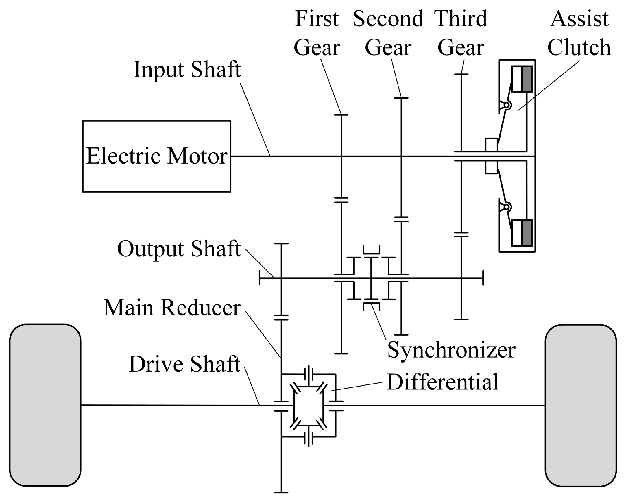
2.1. Drive System Modeling

The drive system of the electric vehicle is shown in Figure 1. The three-speed transmission in the drive system consists of three gear pairs assist clutch installed at the end of input shaft, synchronizer installed on the output shaft, main reducer, and differential. The transmission can achieve gearshift without power interruption between three gears. The upshift process is shown in Figure 2 and Figure 3. Two figures show the torque change of the electric motor, clutch and synchronizer at different shifting phases.
The upshift process from first gear to second gear is divided into the following three phases: the first torque phase, inertia phase, and second torque phase. In the first torque phase, the clutch starts to engage and transmit torque together with the synchronizer. The clutch torque increases, and the synchronizer torque decreases. When the synchronizer does not transmit torque, the synchronizer shall be separated, and the first gear is disengaged. In the inertia phase, by adjusting the speed difference of the clutch, the synchronizer and the second driven gear can rotate synchronously. When the synchronizer is combined, the second gear is engaged. In the second torque phase, the clutch starts to disengage. The process from second gear to third gear is divided into the following two phases: torque phase and inertia phase. In the torque phase, the clutch torque increases. When the synchronizer does not transmit torque, the synchronizer is separated, and the second gear is disengaged. In the inertia phase, the speed difference of the clutch is adjusted to engage the clutch, and the third gear is engaged.
The dynamic model of the drive system is established as shown in Figure 4. The following assumptions are made in the modeling process: (1) the drive shaft is regarded as a spring-damping system, and the other components are regarded as rigid bodies with concentrated inertia; (2) it is assumed that there is no energy loss in the torque transfer process among gears in the transmission. The modeling process of the drive system during shifting is as follows.
The dynamic equation of the input shaft is:
T M T J T A = I M ω ˙ M
where: T M is the electric motor torque, T J is the first or second driving gear torque, J = 1/2, T A is the assist clutch torque, I M is the equivalent moment of inertia of the electric motor, input shaft and components on the input shaft, ω M is the electric motor speed.
The dynamic equation of the drive shaft is:
( T J i J + T A i 3 ) i 0 T D = I D ω ˙ D
where: i J is the gear ratio of gear J, i 3 is the third gear ratio, i 0 is the main reducer ratio, T D is the drive shaft torque, I D is the equivalent moment of inertia of the output shaft, components on the output shaft, drive shaft and components on the drive shaft, ω D is the drive shaft speed.
The dynamic equation of the wheel is:
T D T L = I V ω ˙ V
where: T L is the driving resistance torque, I V is the equivalent moment of inertia of vehicle, ω V is the wheel speed.
The drive shaft is the spring-damping system and the drive shaft torque is:
T D = k D ( θ D θ V ) + c D ( ω D ω V )
where: k D is the drive shaft stiffness coefficient, θ D is the drive shaft rotation angle, θ V is the wheel rotation angle, c D is the drive shaft damping coefficient.
According to the longitudinal dynamics of the vehicle, the driving resistance torque is:
T L = ( m g f r cos α + m g sin α + 1 2 c w A ρ w v 2 ) r w
where: m is the vehicle mass, g is the gravity acceleration, f r is the rolling resistance coefficient, α is the road slope, c w is the air resistance coefficient, A is the vehicle frontal area, ρ w is the air density, v is the driving speed, r w is the wheel radius.

2.2. Clutch Actuator Modeling

The clutch actuator is shown in Figure 5. The actuator is electric, including DC motor and transmission mechanism. The transmission mechanism includes worm gear, connecting rod and shift fork. The DC motor outputs power and drives the connecting rod to move horizontally through a worm gear drive with self-locking. The connecting rod pulls the power arm of the shift fork, and the resistance arm of the shift fork drives the release bearing to move axially. The release bearing drives the diaphragm spring to realize the engagement and disengagement of the clutch.
The dynamic model of the clutch actuator is shown in Figure 6, including the DC motor model and transmission mechanism model. According to Kirchhoff’s theorem and Newton’s second law, the voltage balance equation and torque balance equation of the DC motor model are:
u m = k e θ ˙ m + R m i m + L m i ˙ m I m e θ ¨ m = T m T l b m θ ˙ m
where: u m is the motor control voltage, k e is the motor back electromotive force coefficient, θ m is the motor angle, R m is the motor resistance, i m is motor current, L m is the motor inductance, I m e is the equivalent rotational inertia of the motor and transmission mechanism, T m is the motor torque, T m = k t i m , k t is the motor torque coefficient, T l is motor load torque, b m is the motor rolling damping coefficient.
In the modeling process of the transmission mechanism, the following assumptions are made: (1) each component is regarded as a rigid body; (2) since the travel is short, ignoring the rotation of the connecting rod around the gear center, it is assumed that the connecting rod only moves horizontally. According to the mechanical connection between the motor and the release bearing, the kinematic characteristic between the release bearing displacement and motor rotation angle is obtained:
x = r c l 2 i w l 1 θ m = k m θ m
where: x is the release bearing displacement, r c is the distance between the gear center and connecting rod, i w is the worm gear ratio, l 1 is the length of the shift fork power arm, l 2 is the length of the shift fork resistance arm, k m is the equivalent coefficient.
Considering the modeling error of the transmission mechanism (such as the inertia moment, wear and friction of components), the dynamic characteristics between the release force of the release bearing and the motor load torque are expressed as:
F s = T l η g 1 k θ F f ( θ ˙ m > 0 ) T l k θ η g 2 + F f ( θ ˙ m < 0 )
where: F s is the release force of the release bearing, η g 1 is the total transmission efficiency of the transmission mechanism when the motor rotates forward, η g 2 is the total transmission efficiency of the transmission mechanism when the motor reverses, F f is the modeling error of the transmission mechanism. It is worth noting that when the motor rotates forward, the clutch is separated, and the release force of the release bearing is shown as the load force. When the motor reverses, the clutch is engaged, and the release force is shown as the driving force.
By eliminating the motor current i m and combining the DC motor model and the transmission mechanism model, the state space expression of the clutch actuator model is:
x ˙ 1 = x 2 x ˙ 2 = x 3 x ˙ 3 = m x 2 + n x 3 + o u m + p
where: x 1 , x 2 and x 3 are system state variables, x 1 = x, x 2 = x ˙ , x 3 = x ¨ , m, n, o and p are equivalent coefficients:
m = ( k t k e + R m b m ) I m e L m n = ( R m I m e + L m b m ) I m e L m o = k t k θ I m e L m p = ( F s + F f ) R m k θ 2 I m e L m η g 1 ( F ˙ s + F ˙ f ) k θ 2 I m e η g 1 ( θ ˙ m > 0 ) ( F s F f ) R m k θ 2 η g 2 I m e L m + ( F ˙ s F ˙ f ) k θ 2 η g 2 I m e η g 2 ( θ ˙ m < 0 )
p represents the total disturbance, including load disturbance and modeling error. The main parameters of the drive system and clutch actuator are shown in Table 1. It should be explained that the air density in the table is the value at 20 degrees Celsius under one standard atmospheric pressure, and the relevant parameters of the motor are obtained through measuring experiments.

3. Design of Torque Loop Controller

The torque loop controller converts the reference torque of the clutch into the reference displacement of the release bearing. In order to solve the influence of time-varying parameters of the clutch on the control process under the premise of fast torque tracking, an AFC method is adopted. Meanwhile, to further improve the accuracy and robustness of the controller, a feedback control loop is added on the basis of AFC. Therefore, the torque loop controller adopts the AFFC strategy, and the specific design process is as follows.

3.1. Feedback Control

The feedback controller fine-tunes the release bearing displacement according to the error between the reference torque and the actual torque of the clutch. In this paper, the feedback controller is a supplementary means, so the practical and widely used PID method is used as a feedback controller. However, as an important feedback control input signal, the actual torque of the clutch cannot be obtained directly. Because of the high price of the torque sensor and the limited space of transmission, the torque sensor is not installed in the drive system. So, an observer is needed to estimate the actual torque of the clutch.

3.1.1. Clutch Torque Estimation

Aiming at the problem of clutch torque estimation of three-speed AMT, this paper adopts the estimation method based on drive system dynamics [15] and the following clutch torque estimation scheme is determined: above all, the signals that are easy to obtain, such as electric motor torque, resistance torque, electric motor speed, drive shaft speed and wheel speed are taken as known terms, and drive shaft torque and clutch torque are taken as unknown terms; next, in order to eliminate the influence of measurement noise on speed signals, the speed of the electric motor, drive shaft and wheel is re-estimated by the Luenberger observer with a fast dynamic response; then, the linear observer is used to estimate the drive shaft torque; in the end, the unknown input observer (UIO) with high accuracy and stability is used to estimate the clutch torque [25,26].
According to Equations (1)–(3), the Luenberger observer is used to estimate the electric motor speed, drive shaft speed and wheel speed:
ω ^ ˙ M = 1 I M ( T M T ^ J T ^ A _ u n ) + L 1 ( ω M ω ^ M ) ω ^ ˙ D = 1 I D ( T ^ J i J i 0 + T ^ A i 3 i 0 T ^ D ) + L 2 ( ω D ω ^ D ) ω ^ ˙ V = 1 I V ( T ^ D T L ) + L 3 ( ω V ω ^ V )
where: T ^ A _ u n is the clutch torque estimated by the UIO; L 1 , L 2 and L 3 are Luenberger observer gains.
If Equation (4) is directly used to estimate the drive shaft torque, the drive shaft rotation angle and wheel rotation angle need to be obtained. These two parameters need to be indirectly obtained by integrating the speed signals of the drive shaft and wheel, and the accuracy of the integral results is greatly affected by the measurement noise of the speed signals. In order to avoid the influence of the measurement noise, this article choose to differentiate Equation (4). However, after derivation, the differential of speed signals of the drive shaft and wheel is introduced. Therefore, removing the damping coefficient term of the equation, a linear observer of the drive shaft torque is obtained as follows:
T ^ ˙ D = k d ( ω ^ D ω ^ V ) + L 4 ( ω D ω ^ D ) + L 5 ( ω V ω ^ V )
where: L 4 and L 5 are linear observer gains.
By combining Equations (1) and (2), the UIO of clutch torque is obtained as follows:
I M ω ^ ˙ M i J i 0 + I D ω ^ ˙ D = T M i J i 0 + ( i 3 i 0 i J i 0 ) T ^ A _ u n T ^ D + L 6 δ ˜ T ^ ˙ A _ u n = L 7 δ ˜ δ ˜ = I M ω M i J i 0 I M ω ^ M i J i 0 + I D ω D I D ω ^ D
where: L 6 and L 7 are UIO gains, δ ˜ is the state estimate error.
According to Equation (1), the estimated torque of the gear J is expressed as:
T ^ ˙ D = k d ( ω ^ D ω ^ V ) + L 4 ( ω D ω ^ D ) + L 5 ( ω V ω ^ V )
The above clutch torque observation scheme is simple and reliable, and its stability is obvious, so the stability-proof process is omitted.

3.1.2. PID Control

Through the PID control, the feedback displacement of the release bearing is:
Δ x = k p e + k i 0 t e d t + k d d e d t
where: Δ x is the feedback displacement, k p , k i and k d are proportional, integral and differential gains, respectively, e is the torque tracking error of the clutch:
e = T A _ r e f T ^ A _ u n
where: T A _ r e f is the clutch reference torque.

3.2. Adaptive Feedforward Control

Based on the separation characteristic curve and torque transmission characteristics of the clutch, the AFC law is derived. The specific process is as follows.

3.2.1. Separation Characteristic Curve and Torque Transmission Characteristics

The assist clutch separation characteristic curve obtained by the experiment is shown in Figure 7, which can be divided into three stages: full engagement stage, elastic lever stage and full separated stage [10]. The release bearing displacement in the full engagement stage is obtained by measuring the distance between the release bearing and the small end of the diaphragm spring, and the curve in the elastic lever stage and the full separated stage is obtained by pressure test of the clutch assembly with a press. In the full engagement stage, the release bearing has certain free travel, has not yet contacted with the small end of the diaphragm spring, and the release force of the release bearing is zero. There is preload at the large end of the diaphragm spring, which drives the pressure plate to completely press the driven plate. In the elastic lever stage, as the release bearing displacement increases, the release force increases gradually, and the relationship between the two is basically linear. At the same time, due to the leverage of the diaphragm spring, the pressure of the pressure plate gradually decreases with the increase in the release force. In the fully separated stage, the release force changes nonlinearly with the increase in displacement. The pressure plate is gradually separated from the driven plate until the clutch is completely separated.
Through the above analysis, it can be seen that there is pressure between the pressure plate and the driven plate in the full engagement stage and elastic lever stage, and the clutch transmits torque. In the fully separated stage, the clutch torque is close to zero. The three stages of the separation characteristic curve can be expressed in the form of a piecewise function. The linear fitting of the elastic lever stage curve and the polynomial fitting of the fully separated stage curve are performed to obtain the relationship between the release force and displacement of the release bearing:
F s = 0 ( 0 x x 12 ) f x ( x 12 x x 23 ) f 4 x 4 + f 3 x 3 f 2 x 2 + f 1 x ( x 23 x 10 )
where: f is the linear fitting slope, f 1 , f 2 , f 3 and f 4 are polynomial fitting coefficients, x 12 is the initial contact point between the release bearing and small end of the diaphragm spring, x 23 is the initial separation point between the pressure plate and driven plate.
The diaphragm spring in the elastic lever stage is regarded as a lever, and the pressure of the pressure plate is calculated according to the release force. The relationship between the pressure plate pressure and the release bearing displacement is obtained as follows:
F n = F N ( 0 x x 12 ) F N K f x ( x 12 x x 23 ) 0 ( x 23 x 10 )
where: F n is the pressure plate pressure, F N is the preload at full engagement, K is the leverage ratio of the diaphragm spring.
The clutch torque is calculated by the pressure plate pressure, and the relationship between the clutch torque and the release bearing displacement is obtained as follows:
T A = n R μ F n = n R μ F N ( 0 x x 12 ) n R μ F N n R K μ f x ( x 12 x x 23 ) 0 ( x 23 x 10 )
where: n is the number of friction surfaces, R is the equivalent friction radius, μ is the friction coefficient.
The main parameters of the assist clutch involved in the above equations are shown in Table 2.

3.2.2. Adaptive Estimation of Time-Varying Parameters

It can be seen from the introduction that the relationship between the torque and position is affected by time-varying parameters of the clutch, which can be divided into the following three aspects: (1) change of friction coefficient caused by speed difference, driven plate wear and temperature; (2) the wear of the driven plate makes the curve of the elastic lever stage and the full separated stage translate in the direction of the release bearing displacement axis; (3) the artificially introduced linear fitting slope error when the curve in the elastic lever stage is linearly fitted. It can be seen from Equation (19) that the above time-varying parameters mainly affect the elastic lever stage, so the elastic lever stage is analyzed separately. For the purpose of improving the accuracy of the clutch torque transmission characteristics, uncertainties of time-varying parameters are added. The relationship between clutch torque and release bearing displacement can be further expressed as:
T A = n R ( μ + Δ μ ) F N n R K ( μ + Δ μ ) ( f + Δ f ) ( x + Δ x ) = n R μ F N + n R Δ μ F N n R K μ f x n R K Δ w x n R K Δ z
where: Δ μ is the friction coefficient uncertainty, Δ f is the linear fitting slope uncertainty, Δ x is the translation amount of the separation characteristic curve, Δ w and Δ z are the uncertainty coupling terms, Δ w and Δ z are:
Δ w = μ Δ f + Δ μ f + Δ μ Δ f Δ z = μ f Δ x + Δ w Δ x
In Equation (20), the friction coefficient uncertainty and uncertainty coupling terms are unknown and need to be estimated adaptively. According to the practical application of the clutch and Equation (21), it is easy to know that the friction coefficient uncertainty and uncertainty coupling terms are bounded.
Adaptive laws of friction coefficient uncertainty and uncertainty coupling terms are derived by adaptive estimation of the clutch actual torque. To obtain the adaptive law of the clutch actual torque, the clutch torque estimated by the UIO in Section 3.1.1 is used as a known term, and a first-order filter is applied to Equation (20):
T ^ ˙ A _ u n = γ a [ T ^ A _ u n ( n R μ F N n R K μ f x + n R Δ μ F N n R K Δ w x n R K Δ z ) ]
where: γ a is the first-order filter gain, γ a > 0.
The adaptive law of the estimation form corresponding to Equation (22) is:
T ^ ˙ A _ a d = γ a [ T ^ A _ a d ( n R μ F N n R K μ f x + n R Δ μ ^ F N n R K Δ w ^ x n R K Δ z ^ ) ]
where: T ^ A _ a d is the adaptive estimated clutch torque.
Based on the Lyapunov stability theory, adaptive laws of friction coefficient uncertainty and uncertainty coupling terms are:
Δ μ ^ ˙ = γ a γ μ n R F N ε Δ w ^ ˙ = γ a γ w n R K x ε Δ z ^ ˙ = γ a γ z n R K ε ε = T ^ A _ u n T ^ A _ a d
where: γ μ , γ w and γ z are adaptive gains, γ μ > 0, γ w > 0, γ z > 0, ε is the error between the clutch torque estimated by the UIO and adaptive law.

3.2.3. Stability Analysis

The stability of adaptive laws is proved as follows, and estimation errors of the friction coefficient uncertainty and the uncertainty coupling terms are defined:
Δ μ ˜ = Δ μ Δ μ ^ Δ w ˜ = Δ w Δ w ^ Δ z ˜ = Δ z Δ z ^
Define the Lyapunov function in the following form:
V = 1 2 ε 2 + 1 2 γ μ Δ μ ˜ 2 + 1 2 γ w Δ w ˜ 2 + 1 2 γ z Δ z ˜ 2
The derivative of V is:
V ˙ = ε ε ˙ + 1 γ μ Δ μ ˜ Δ μ ˜ ˙ + 1 γ w Δ w ˜ Δ w ˜ ˙ + 1 γ z Δ z ˜ Δ z ˜ ˙ = ε γ a [ T ^ A _ u n ( n R μ F N n R K μ f x + n R Δ μ F N n R K Δ w x n R K Δ z ) ] + γ a [ T ^ A _ a d ( n R μ F N n R K μ f x + n R Δ μ ^ F N n R K Δ w ^ x n R K Δ z ^ ) ] 1 γ μ Δ μ ˜ Δ μ ^ ˙ 1 γ w Δ w ˜ Δ w ^ ˙ 1 γ z Δ z ˜ Δ z ^ ˙ = ε ( γ a ε + γ a n R Δ μ ˜ F N γ a n R K Δ w ˜ x γ a n R K Δ z ˜ ) 1 γ μ Δ μ ˜ Δ μ ^ ˙ 1 γ w Δ w ˜ Δ w ^ ˙ 1 γ z Δ z ˜ Δ z ^ ˙ = γ a ε 2 + γ a n R Δ μ ˜ F N ε γ a n R K Δ w ˜ x ε γ a n R K Δ z ˜ ε 1 γ μ Δ μ ˜ Δ μ ^ ˙ 1 γ w Δ w ˜ Δ w ^ ˙ 1 γ z Δ z ˜ Δ z ^ ˙ = γ a ε 2 + Δ μ ˜ ( γ a n R F N ε 1 γ μ Δ μ ^ ˙ ) Δ w ˜ ( γ a n R K x ε + 1 γ w Δ w ^ ˙ ) Δ z ˜ ( γ a n R K ε + 1 γ z Δ z ^ ˙ ) = γ a ε 2 < 0
By taking adaptive laws of the friction coefficient uncertainty and uncertainty coupling terms into the above equation, it can be obtained that V ˙ < 0 . In addition, V ˙ ( 0 ) = 0 . Based on the Lyapunov stability theory, all errors are asymptotically stable at the origin.

3.2.4. Feedforward Control

The clutch reference torque and uncertainties of adaptive estimation are brought into Equation (20), and the feedforward displacement of the release bearing is obtained as:
x b = T A _ r e f n R μ F N n R Δ μ ^ F N n R K Δ z ^ n R K μ f n R K Δ w ^
where: x b is the feedforward displacement.
Finally, by adding the feedback displacement and the feedforward displacement, the reference displacement of the release bearing is obtained as:
x r e f = x b + Δ x
where: x r e f is the reference displacement of the release bearing.

4. Design of Position Loop Controller

The position loop controller adopts the B-ARDC method, takes the reference displacement of the release bearing as the input, and outputs the control voltage of the clutch actuator motor. The B-ADRC takes the traditional ADRC as the framework and selects the backstepping method as the nonlinear feedback controller, which includes three parts: tracking differentiator, backstepping controller and ESO. The ESO is used to estimate the load disturbance and unknown disturbance of the system. The design process of the position loop controller is as follows.

4.1. Tracking Differentiator

The tracking differentiator preprocesses the signal, takes the reference displacement as input, and outputs the processed reference displacement, reference velocity and reference acceleration. In the actual control process, the reference displacement signal is usually accompanied by noise interference, and the velocity and acceleration need to differentiate and quadratic differential the reference displacement. Differentiation of noisy signals may lead to signal distortion after differentiation. For the sake of reducing noise interference and obtaining effective differential signals, a nonlinear tracking differentiator is used to preprocess the signal. Taking displacement and velocity as an example, the form of the nonlinear tracking differentiator is as follows:
v 1 ( k + 1 ) = v 1 ( k ) + h v 2 ( k ) v 2 ( k + 1 ) = v 2 ( k ) + h f h a n ( v 1 x r e f , v 2 , r 0 , h 0 )
where: v 1 is the preprocessed reference displacement, v 2 is the preprocessed reference velocity, k is the sampling number, h is the sampling period, r 0 and h 0 are adjusting factors, f h a n is the optimal synthesis function, the form is as follows:
f h a n ( v 1 x r e f , v 2 , r 0 , h 0 ) = r 0 a d sign ( a ) s a r 0 sign ( a )
The parameters in the above equation are as follows:
d = r 0 h 0 2 a 0 = h 0 v 2 y = v 1 x r e f + a 0 a 1 = d ( d + 8 y ) a 2 = a 0 + sign ( y ) a 1 d 2 a = ( a 0 + y a 2 ) s y + a 2 s a = sign ( a + d ) sign ( a d ) 2 s y = sign ( y + d ) sign ( y d ) 2
Sign(·) is a sign function. With the preprocessed reference velocity v 2 as input, the preprocessed reference acceleration v 3 can be obtained by applying the above nonlinear tracking differentiator again. To avoid duplication, the specific process is omitted.

4.2. Extended State Observer

Except that the actual displacement of the release bearing can be directly measured by the displacement sensor installed in the clutch actuator, the remaining state variables and total disturbance cannot be directly obtained. In this paper, the ESO is used to estimate the state variables and total disturbance.
The total disturbance in Equation (9) is taken as a new state variable x 4 , and x 4 = p . The extended state space of the clutch actuator model is:
x ˙ 1 = x 2 x ˙ 2 = x 3 x ˙ 3 = m x 2 + n x 3 + o u m + x 4 x ˙ 4 = p ˙
Establish ESO for the extended state space:
x ^ ˙ 1 = x ^ 2 + β 1 ( x 1 x ^ 1 ) x ^ ˙ 2 = x ^ 3 + β 2 ( x 1 x ^ 1 ) x ^ ˙ 3 = m x ^ 2 + n x ^ 3 + o u m + x ^ 4 + β 3 ( x 1 x ^ 1 ) x ^ ˙ 4 = β 4 ( x 1 x ^ 1 )
where: β 1 , β 2 , β 3 and β 4 are ESO gains. Whether the gain selection is reasonable or not determines the estimation performance of the observer. Due to the large number of ESO gains, the parameter tuning process is difficult. In order to reduce the difficulty of the parameter tuning process under the premise of ensuring the estimation performance of the observer, the bandwidth method proposed by Gao et al. [27] is used for gain tuning.
Define the estimation error of the state variable: x ˜ j = x j x ^ j , j = 1, 2, 3, 4. From Equations (33) and (34), the estimation error of the ESO is:
x ˜ ˙ 1 = x ˜ 2 β 1 x ˜ 1 x ˜ ˙ 2 = x ˜ 3 β 2 x ˜ 1 x ˜ ˙ 3 = m x ˜ 2 + n x ˜ 3 + x ˜ 4 β 3 x ˜ 1 x ˜ ˙ 4 = β 4 x ˜ 1
Let the state variable estimation error matrix be:
E = [ x ˜ 1 x ˜ 2 x ˜ 3 x ˜ 4 ] T
where: E is the state variable estimation error matrix. Equation (35) can be expressed as:
E ˙ = G E + H p ˙
where: G and H are coefficient matrices:
G = β 1 1 0 0 β 2 0 1 0 β 3 m n 1 β 4 0 0 0 H = 0 0 0 1
To ensure the estimation error convergence of the ESO, the coefficient matrix G should be a Hurwitz matrix, and all eigenvalues of the matrix should be located in the left half plane of the s domain. The characteristic polynomial of the coefficient matrix G is:
λ G = λ 4 + ( β 1 n ) λ 3 + ( β 2 β 1 n m ) λ 2 + ( β 3 β 2 n β 1 m ) λ + β 4
where: λ G is the characteristic polynomial of the matrix G , λ is the eigenvalue of the matrix G .
The ideal characteristic polynomial established by the bandwidth method is:
λ IG = λ 4 + 4 ω 0 λ 3 + 6 ω 0 2 λ 2 + 4 ω 0 3 λ + ω 0 4
where: λ IG is the ideal characteristic polynomial of the matrix G , ω 0 is the ESO bandwidth, ω 0 > 0.
Through one-to-one correspondence of the coefficients in Equations (39) and (40), all gains of the ESO are obtained as follows:
β 1 = 4 ω 0 + n β 2 = 6 ω 0 2 + 4 ω 0 n + n 2 + m β 3 = 4 ω 0 3 + 6 ω 0 2 n + 4 ω 0 ( m + n 2 ) + n 3 + 2 m n β 4 = ω 0 4
Through the conversion of the bandwidth method, the ESO bandwidth becomes the only tuning parameter, which greatly reduces the difficulty of gain tuning.

4.3. Backstepping Controller

The position control of the release bearing needs to achieve two goals of nonlinear tracking and disturbance rejection. The backstepping control method is an important method to deal with such problems and has a wide range of applications. The design process of the backstepping controller is as follows.
(1)
The displacement tracking error of the release bearing is defined as:
z 1 = x 1 v 1
where: z 1 is the displacement tracking error of the release bearing.
Considering the subsystem z 1 , x 2 is taken as the virtual control input of the subsystem z 1 , and the virtual control error of x 2 is defined as:
z 2 = x 2 α 1
where: z 2 is the virtual control error of x 2 , α 1 is the virtual stabilizing controller.
To ensure the asymptotic stability of the subsystem z 1 , α 1 is selected as:
α 1 = k 1 z 1 + v 2
where: k 1 is the backstepping controller gain, k 1 > 0.
The Lyapunov function is defined as:
V 1 = 1 2 z 1 2
The derivative of V 1 is:
V ˙ 1 = z 1 ( x ˙ 1 v ˙ 1 ) = z 1 ( z 2 + α 1 v 2 ) = k 1 z 1 2 + z 1 z 2
(2)
Considering the subsystem ( z 1 , z 2 ):
z ˙ 1 = x ˙ 1 v ˙ 1 = z 2 + α 1 v 2 = k 1 z 1 + z 2 z ˙ 2 = x ˙ 2 α ˙ 1 = x 3 α 1 x 1 x ˙ 1 + α 1 v 1 v ˙ 1 + α 1 v 2 v ˙ 2 = x 3 + k 1 x 2 k 1 v 2 v 3
x 3 is taken as the virtual control input of the subsystem ( z 1 , z 2 ), and the virtual control error of x 3 is defined as:
z 3 = x 3 α 2
where: z 3 is the virtual control error of x 3 , α 2 is the virtual stabilizing controller.
To ensure the asymptotic stability of the subsystem ( z 1 , z 2 ), α 2 is selected as:
α 2 = k 2 z 2 z 1 k 1 x 2 + k 1 v 2 + v 3
where: k 2 is the backstepping controller gain, k 2 > 0.
The Lyapunov function is defined as:
V 2 = V 1 + 1 2 z 2 2
The derivative of V 2 is:
V ˙ 2 = k 1 z 1 2 + z 1 z 2 + z 2 z ˙ 2 = k 1 z 1 2 + z 2 ( z 1 + x 3 + k 1 x 2 k 1 v 2 v 3 ) = k 1 z 1 2 + z 2 ( z 1 + z 3 + α 2 + k 1 x 2 k 1 v 2 v 3 ) = k 1 z 1 2 k 2 z 2 2 + z 2 z 3
(3)
Considering the entire system, the derivative of z 3 is:
z ˙ 3 = x ˙ 3 α ˙ 2 = m x 2 + n x 3 + o u m + p α 2 x 1 x ˙ 1 + α 2 x 2 x ˙ 2 + α 2 v 1 v ˙ 1 + α 2 v 2 v ˙ 2 + α 2 v ˙ 2 v ¨ 2 = m x 2 + n x 3 + o u m + p + ( k 1 k 2 + 1 ) x 2 + ( k 1 + k 2 ) x 3 ( k 1 k 2 + 1 ) v 2 ( k 1 + k 2 ) v 3 v ˙ 3
The Lyapunov function is defined as:
V 3 = V 2 + 1 2 z 3 2
The derivative of V 3 is:
V ˙ 3 = k 1 z 1 2 k 2 z 2 2 + z 2 z 3 + z 3 z ˙ 3 = k 1 z 1 2 k 2 z 2 2 + z 3 z 2 + m x 2 + n x 3 + o u m + p + ( k 1 k 2 + 1 ) x 2 + ( k 1 + k 2 ) x 3 ( k 1 k 2 + 1 ) v 2 ( k 1 + k 2 ) v 3 v ˙ 3
Select the control law:
u m = 1 o k 3 z 3 z 2 m x 2 n x 3 p ( k 1 k 2 + 1 ) x 2 ( k 1 + k 2 ) x 3 + ( k 1 k 2 + 1 ) v 2 + ( k 1 + k 2 ) v 3 + v ˙ 3
where: k 3 is the backstepping controller gain, k 3 > 0.
Substituting the control law into Equation (54), we can obtain:
V ˙ 3 = k 1 z 1 2 k 2 z 2 2 k 3 z 3 3 < 0 ( z 1 0 , z 2 0 , z 3 0 )
According to Lyapunov stability theory, the controller is asymptotically stable.

5. Double-Loop Controller and Simulation Analysis

The torque loop controller and position loop controller are cascaded to obtain the dual-loop controller, the structure is shown in Figure 8.
In order to verify the effectiveness of the dual-loop controller, the MATLAB/SIMULINK simulation platform is used to build the simulation model of the dual-loop controller according to Figure 8, and the clutch torque tracking control simulation of the three-speed AMT shift process is carried out. The drive system, clutch actuator and clutch in the simulation model have been established in Section 2 and Section 3.2.1. The shift control method of the AMT adopts the sectional control strategy [28,29]. In the torque phase, the clutch torque increases or decreases linearly by using the linear feedforward control method. In the inertial phase, the PID control method is used to realize the tracking control of the expected speed difference between the driving and driven plate of the clutch, and the clutch torque is kept constant. The reference torque trajectory of the clutch during shifting is shown in Figure 9.

5.1. Simulation of Torque Loop controller

For the purpose of investigating the control performance of the AFFC, PID control [16] and AFC (compared with the AFFC, the AFC removes the PID feedback control loop) are selected as the comparison control methods. To reduce the influence of the position loop controller on the torque loop controller, the position loop controller and clutch actuator are omitted in the simulation model of this section, and the reference displacement output by the torque loop controller is directly applied to the clutch model. In addition, in order to simulate the change of friction coefficient and driven plate wear as much as possible, different friction coefficient uncertainties and translation amounts of separation characteristic curves are added to the clutch model. The following three simulation conditions are set: (1) The clutch model does not change ( Δ μ = 0, Δ x = 0 mm); (2) The parameters of the clutch model change ( Δ μ = −0.1, Δ x = 0.1 mm); (3) The change of clutch model parameters increases ( Δ μ = −0.2, Δ x = 0.2 mm).
The tuning method of control parameters adopts the trial and error method. The controller parameters are repeatedly adjusted according to the simulation experience, and the set of parameters with the best tracking control performance is selected as the final control parameters. The parameters of the AFFC are determined as follows. The gains of the Luenberger observer, linear observer and UIO are L 1 = 110 , L 2 = 210 , L 3 = 220 , L 4 = 650 , L 5 = 1200 , L 6 = 45 , L 7 = 2000 . The PID controller parameters are k p = 0.1 , k i = 0.9 , k d = 0.01 . The first-order filter gain and adaptive gains are γ a = 100 , γ μ = 0.00001 , γ w = 0.5 , γ z = 0.15 . The control performance of torque loop controllers under three simulation conditions is shown in Figure 10, Figure 11 and Figure 12.
It can be seen from Figure 10 that when the clutch model has not changed, the three controllers all show good control effects. The tracking error mainly exists in the torque phase, because the clutch reference torque changes from a constant state to a linear change state similar to the ramp signal in the torque phase. For example, at 0.2 s, the PID controller has a certain degree of tracking hysteresis, and the settling time is about 0.3 s, basically occupying the whole first torque phase. Compared with the PID controller, the AFC and AFFC have faster response speeds. The settling time of the AFC is about 0.25 s, and the AFFC has the least settling time of 0.1 s. In Figure 11, the clutch model changes due to the influence of time-varying parameters. Although the settling time of the three controllers remains the same as that of the first simulation condition, the tracking errors have slightly increased. The PID controller is greatly affected by the change of clutch model, especially in the inertial phase, a slight buffeting phenomenon occurs, and the buffeting amplitude is about 0.4 Nm. Figure 11c,d show the adaptive estimations of the friction coefficient uncertainty and translation amount of AFC and AFFC. Two parameters are constantly corrected as the clutch reference torque changes. The steady-state values of the two parameters are −0.111 and 0.092, respectively, close to the set value, and the time-varying parameter adaptive estimation is basically realized. Because of the additional PID control loop, the overall tracking error of the AFFC is smaller than AFC, and the stable tracking performance can be recovered after a short time of adjustment. The clutch model in Figure 12 is more affected by time-varying parameters. The tracking errors of the three controllers are further increased compared to the second simulation condition. The tracking error of the PID controller increases significantly, and the maximum error is close to −10 Nm. There is a large buffeting phenomenon in the inertial phase, and the maximum buffeting amplitude is about 1.4 Nm, which is difficult to maintain stability. The steady-state values of the friction coefficient uncertainty and translation amount are −1.888 and 0.184, and the error with the set value increases, but the control performance of the AFC and AFFC is still better than the PID controller. In summary, the AFFC combines the advantages of AFC and PID control and has a faster settling speed, higher accuracy and stronger robustness.

5.2. Simulation of Position Loop Controller

The clutch reference torque in Section 5.1 is converted into the reference displacement of the release bearing, and the displacement for the simulation of the position loop controller is used. The reference displacement trajectory is shown in Figure 13. At the first or second gear, the clutch is completely disengaged, and the release bearing is at the 10 mm position. During upshifting, the release bearing quickly moves to the elastic lever stage, similar to the step signal. In the elastic lever stage, the reference displacement is nonlinear, which requires the controller to have good dynamic tracking performance. At the third gear, the clutch is fully engaged and the release bearing is at the position of 0 mm.
For the sake of investigating the displacement tracking performance of the B-ADRC, PID control [16] and traditional ADRC [24] are selected as the contrast control methods. Different from the B-ADRC, the traditional ADRC combines the system state errors nonlinearly to form a nonlinear error feedback control law. To compare the anti-interference performance of controllers, the following three simulation conditions can be set: (1) ignoring load disturbance of clutch and modeling error of the clutch actuator, the system is not disturbed; (2) the system is subjected to the load disturbance of the clutch and the modeling error of the clutch actuator. The magnitude of the load disturbance is related to the position of the release bearing, which can be obtained by the separation characteristic curve. The modeling error is set to a fixed value of 20N; (3) under the same disturbance as condition (2), the reference torque of the clutch is expanded to three times of the original torque to simulate the tracking performance under higher shifting torque.
The selected parameters of the B-ARDC are as follows. The sampling period and adjusting factors of the tracking differentiator are h = 0.01 , r 0 = 10 , 000 , h 0 = 0.01 . The ESO bandwidth ω 0 = 20 . The backstepping controller gains are k 1 = 100 , k 2 = 80 , k 3 = 50 . The control performance of position loop controllers under three simulation conditions is shown in Figure 14, Figure 15 and Figure 16.
It can be seen from Figure 14 that when the system is not disturbed, the three controllers have good displacement tracking effects. The tracking error occurs only in the step response, and then stable tracking can be achieved quickly without a large overshoot. The settling time of controllers can be maintained within 0.2 s, and the steady-state error does not exceed 0.1 mm. In Figure 15, the control performance of controllers decreases slightly due to the load disturbance and modeling error. The control performance of the PID controller is poor, especially in the nonlinear tracking and step tracking stages after 0.9 s, there are large tracking errors and overshoot. The maximum overshoot is 1.19 mm, and the settling time is also increased to 0.25 s. Compared with the PID controller, the ARDC and B-ARDC have better control performance. The settling time of the ARDC and B-ARDC is 0.12 s and 0.06 s, respectively. Since the total disturbance of the system can be estimated by the ESO and compensated by the feedback controller, the two controllers have stronger robustness. In addition, compared with the ARDC, the B-ARDC has smaller tracking errors and shorter settling times. The reference torque of the clutch in Figure 16 increases, so the release bearing displacement in the elastic lever stage increases. The larger reference displacement increases the difficulty of control and the control effects of controllers are further reduced. However, the transient performance of the B-ARDC is still the best among the three controllers. To sum up, the B-ARDC has the best rapidity, accuracy and anti-interference performance.

5.3. Simulation of Double-Loop Controller

The control performance of the torque loop controller and position loop controller is analyzed separately above. To verify the effectiveness of the dual-loop controller, the torque loop and position loop controllers are combined to form a complete dual-loop controller (AFFC+B-ARDC). In contrast, the PID controller is applied to both the torque loop and position loop (PID+PID). Considering the time-varying parameters of the clutch model and the disturbance to the clutch actuator, the simulation conditions are set as follows: Δ μ = −0.2, Δ x = 0.2 mm, and the clutch actuator is disturbed by the load disturbance and 20N modeling error. The control performance of the two double-loop controllers is shown in Figure 17.
It can be seen from Figure 17a,b that the tracking errors of the AFFC+B-ARDC and PID+PID controller are greatly increased compared with the simulation results of Section 5.1, and the maximum tracking errors are 9.85 Nm and −18.09 Nm, respectively. This is because there are tracking errors in both control loops, and the tracking errors are superimposed in the cascade control. In addition, the disturbance of the torque loop and position loop further increases the torque tracking error of dual-loop controllers. The tracking error ranges of the two controllers are within (−9.08, 9.85) and (−18.09, 14.84). The overall tracking error of the AFFC+B-ARDC is smaller than the PID+PID controller, which means that the torque tracking accuracy of the dual-loop controller is higher. It can be inferred from Figure 17c–e that the overall torque tracking error of the double-loop controller proposed in this paper is lower for two reasons. In the torque loop, the AFFC outputs more stable reference displacement than the PID controller. In the position loop, the B-ARDC has less position tracking error and settling time than the PID controller. For example, at 0.2 s, the settling time of the two controllers is 0.09 s and 0.26 s, respectively. In conclusion, the dual-loop controller proposed in this paper can not only achieve torque tracking control but also have high tracking accuracy.

6. Conclusions

Aiming at the clutch torque tracking control, this paper presents a double-loop control method that cascade controls the torque loop controller and position loop controller. Firstly, the dynamic models of the AMT drive system and clutch actuator are established. Then, the AFFC is adopted in the torque loop to solve the time-varying parameter problem of the clutch, and the B-ARDC is adopted in the position loop to solve the nonlinearity and interference problems of the position tracking control process. Finally, using the MATLAB/SIMULINK simulation platform, the torque tracking control process of the clutch is simulated. The main contributions of this paper are as follows:
  • A double-loop controller with cascade control of torque loop and position loop controller is proposed to achieve torque tracking control of the dry clutch.
  • The torque loop controller can adaptively control according to different time-varying parameters of the clutch, integrates the advantages of feedforward and feedback control and has fast response speed, high accuracy and strong robustness.
  • The position loop controller can achieve fast and stable position tracking of the release bearing in the presence of load disturbance and unknown disturbance, and has a stronger anti-interference ability.
  • Compared with the PID controller, the proposed double-loop controller can achieve better torque tracking performance, which preliminarily verifies the feasibility of the double-loop controller.
The theoretical research and simulation analysis of the double-loop controller have been completed. In future work, bench tests are needed to further verify the effectiveness of the controller.

Author Contributions

Conceptualization, P.W. and H.Z.; methodology, P.W.; software, P.W.; validation, P.W., H.Z. and T.P.; formal analysis, P.W.; investigation, P.W.; resources, P.W., P.Q. and T.P.; data curation, P.Q. and T.P.; writing—original draft preparation, P.W.; writing—review and editing, H.Z.; visualization, P.W.; supervision, T.P.; project administration, P.Q.; funding acquisition, H.Z. All authors have read and agreed to the published version of the manuscript.

Funding

Supported by National Natural Science Foundation of China (61573304).

Data Availability Statement

Not applicable.

Conflicts of Interest

The authors declare no conflict of interest.

Abbreviations

The following abbreviations are used in this manuscript:
AFCAdaptive feedforward control
AFFCAdaptive feedforward-feedback control
AMTAutomatic mechanical transmission
ARDCActive disturbance rejection control
B-ARDCBackstepping based active disturbance rejection control
DCDirect current
ESOExtended state observer
PIDProportional-integral-derivative
UIOUnknown input observer

References

  1. Laukenmann, M.A.; Sawodny, O. Model-Based control of a clutch actuator used in hybrid dual-clutch transmissions. Mechatronics 2021, 77, 102585. [Google Scholar] [CrossRef]
  2. Huang, B.; Wu, S.; Huang, S.; Fu, X.; Yang, Y. Clutch control of a hybrid electrical vehicle based on neuron-adaptive PID algorithm. Clust. Comput. 2019, 22, 12091–12099. [Google Scholar] [CrossRef]
  3. Sharifzadeh, M.; Pisaturo, M.; Farnam, A.; Senatore, A. Joint structure for the real-time estimation and control of automotive dry clutch engagement. IFAC-PapersOnLine 2018, 51, 1062–1067. [Google Scholar] [CrossRef]
  4. Meng, F.; Tao, G.; Zhang, T.; Hu, Y.; Geng, P. Optimal shifting control strategy in inertia phase of an automatic transmission for automotive applications. Mech. Syst. Signal Process. 2015, 60, 742–752. [Google Scholar] [CrossRef]
  5. Ouyang, T.; Lu, Y.; Li, S.; Yang, R.; Xu, P.; Chen, N. An improved smooth shift strategy for clutch mechanism of heavy tractor semi-trailer automatic transmission. Control. Eng. Pract. 2022, 121, 105040. [Google Scholar] [CrossRef]
  6. Shi, J.; Li, L.; Wang, X.; Liu, C. Robust output feedback controller with high-gain observer for automatic clutch. Mech. Syst. Signal Process. 2019, 132, 806–822. [Google Scholar] [CrossRef]
  7. Yang, C.; Jiao, X.; Li, L.; Zhang, Y.; Chen, Z. A robust H control-based hierarchical mode transition control system for plug-in hybrid electric vehicle. Mech. Syst. Signal Process. 2018, 99, 326–344. [Google Scholar] [CrossRef]
  8. Oh, J.J.; Eo, J.S.; Choi, S.B. Torque observer-based control of self-energizing clutch actuator for dual clutch transmission. IEEE Trans. Control Syst. Technol. 2016, 25, 1856–1864. [Google Scholar] [CrossRef]
  9. Temporelli, R.; Boisvert, M.; Micheau, P. Accurate clutch slip controllers during vehicle steady and acceleration states. IEEE/ASME Trans. Mechatron. 2018, 23, 2078–2089. [Google Scholar] [CrossRef]
  10. Li, L.; Wang, X.; Qi, X.; Li, X.; Cao, D.; Zhu, Z. Automatic clutch control based on estimation of resistance torque for AMT. IEEE/ASME Trans. Mechatron. 2016, 21, 2682–2693. [Google Scholar] [CrossRef]
  11. Vasca, F.; Iannelli, L.; Senatore, A.; Reale, G. Torque transmissibility assessment for automotive dry-clutch engagement. IEEE/ASME Trans. Mechatron. 2010, 16, 564–573. [Google Scholar] [CrossRef]
  12. Gao, B.; Hong, J.; Qu, T.; Yu, S.; Chen, H. An output regulator with rejection of time-varying disturbance: Experimental validation on clutch slip control. IEEE Trans. Control. Syst. Technol. 2019, 28, 1158–1167. [Google Scholar] [CrossRef]
  13. Kim, J.; Choi, S.B.; Oh, J.J. Adaptive engagement control of a self-energizing clutch actuator system based on robust position tracking. IEEE/ASME Trans. Mechatron. 2018, 23, 800–810. [Google Scholar] [CrossRef]
  14. Park, J.; Choi, S.; Oh, J.; Eo, J. Adaptive slip engagement control of a wet clutch in vehicle powertrain based on transmitted torque estimation. Mech. Syst. Signal Process. 2022, 171, 108861. [Google Scholar] [CrossRef]
  15. Kim, S.; Choi, S. Control-oriented modeling and torque estimations for vehicle driveline with dual-clutch transmission. Mech. Mach. Theory 2018, 121, 633–649. [Google Scholar] [CrossRef]
  16. WU, X.; Zhang, X.; Chen, H.; Yang, M. Torque Tracking PID Control for HEV Automatic Diaphragm Spring Clutch. Trans. Beijing Inst. Technol. 2017, 37, 1072–1076. [Google Scholar]
  17. Wang, X.; Li, L.; Yang, C. Hierarchical control of dry clutch for engine-start process in a parallel hybrid electric vehicle. IEEE Trans. Transp. Electrif. 2016, 2, 231–243. [Google Scholar] [CrossRef]
  18. Yonggang, L.; Jingchen, Z.; Yougang, W.; Dongye, S.; Datong, Q. Adaptive shifting control for data driven dual clutch transmission. Automot. Eng. 2021, 43, 891–898+923. [Google Scholar]
  19. Kurniawan, E.; Harno, H.; Wang, H.; Prakosa, J.; Sirenden, B.; Septanto, H.; Adinanta, H.; Rahmatillah, A. Robust adaptive repetitive control for unknown linear systems with odd-harmonics periodic disturbances. Sci. China Inf. Sci 2022, 1, 1–18. [Google Scholar] [CrossRef]
  20. Kurniawan, E.; Zhenwei, C.; Zhihong, M. Digital design of adaptive repetitive control of linear systems with time-varying periodic disturbances. IET Control Theory Appl. 2014, 8, 1995–2003. [Google Scholar] [CrossRef]
  21. Wu, M. Hamilton Jacobi Inequality based sliding mode robust control for optimal torque transmissions of Dry Dual Clutch assembly in torque phase of shift. In Proceedings of the 2017 IEEE International Conference on Mechatronics and Automation (ICMA), Takamatsu, Japan, 6–9 August 2017; pp. 1900–1905. [Google Scholar]
  22. Mishra, K.D.; Srinivasan, K. Robust control and estimation of clutch-to-clutch shifts. Control Eng. Pract. 2017, 65, 100–114. [Google Scholar] [CrossRef]
  23. Li, L.; Wang, X.; Hu, X.; Chen, Z. A Modified PFC with Sliding Mode Observer for Automated Dry Clutch Control of Vehicle. J. Dyn. Syst. Meas. Control 2016, 136, 061005. [Google Scholar] [CrossRef]
  24. Gao, Y.; Liu, Q.; Li, C.; Chen, H. Launch control strategy for AMT vehicles based on ADRC. In Proceedings of the 26th Chinese Control and Decision Conference (2014 CCDC), Changsha, China, 6–9 August 2014; pp. 681–686. [Google Scholar]
  25. Oh, J.J.; Choi, S.B.; Kim, J. Driveline modeling and estimation of individual clutch torque during gear shifts for dual clutch transmission. Mechatronics 2014, 24, 449–463. [Google Scholar] [CrossRef]
  26. Sooyoung, K.; Oh, J.J.; Choi, S.B. Driveline Torque Estimations for a Ground Vehicle With Dual-Clutch Transmission. IEEE Trans. Veh. Technol. 2017, 67, 1977–1989. [Google Scholar]
  27. Zheng, Q.; Gaol, L.Q.; Gao, Z. On stability analysis of active disturbance rejection control for nonlinear time-varying plants with unknown dynamics. In Proceedings of the 2007 46th IEEE Conference on Decision and Control, New Orleans, LA, USA, 12–14 December 2007; pp. 3501–3506. [Google Scholar]
  28. Gao, B.; Liang, Q.; Xiang, Y.; Guo, L.; Chen, H. Gear ratio optimization and shift control of 2-speed I-AMT in electric vehicle. Mech. Syst. Signal Process. 2015, 50, 615–631. [Google Scholar] [CrossRef]
  29. Tian, Y.; Ruan, J.; Zhang, N.; Wu, J.; Walker, P. Modelling and control of a novel two-speed transmission for electric vehicles. Mech. Mach. Theory 2018, 127, 13–32. [Google Scholar] [CrossRef]
Figure 1. Schematic diagram of the drive system.
Machines 10 01142 g001
Figure 2. Schematic diagram from first gear to second gear.
Machines 10 01142 g002
Figure 3. Schematic diagram from second gear to third gear.
Machines 10 01142 g003
Figure 4. Dynamic model of the drive system.
Machines 10 01142 g004
Figure 5. Schematic diagram of the clutch actuator.
Machines 10 01142 g005
Figure 6. Dynamic model of the clutch actuator.
Machines 10 01142 g006
Figure 7. Separation characteristic curve of the clutch.
Machines 10 01142 g007
Figure 8. Schematic diagram of the double-loop controller.
Machines 10 01142 g008
Figure 9. Reference torque trajectory of the clutch.
Machines 10 01142 g009
Figure 10. Performance comparison of torque loop controllers under the first simulation condition: (a) Clutch Torque; (b) Torque Error.
Machines 10 01142 g010
Figure 11. Performance comparison of torque loop controllers under the second simulation condition: (a) Clutch Torque; (b) Torque Error; (c) Friction Coefficient Uncertainty; (d) Translation Amount.
Machines 10 01142 g011
Figure 12. Performance comparison of torque loop controllers under the third simulation condition: (a) Clutch Torque; (b) Torque Error; (c) Friction Coefficient Uncertainty; (d) Translation Amount.
Machines 10 01142 g012
Figure 13. Reference displacement trajectory of the release bearing.
Machines 10 01142 g013
Figure 14. Performance comparison of position loop controllers under the first simulation condition: (a) Clutch Position; (b) Position Error.
Machines 10 01142 g014
Figure 15. Performance comparison of position loop controllers under the second simulation condition: (a) Clutch Position; (b) Position Error.
Machines 10 01142 g015
Figure 16. Performance comparison of position loop controllers under the third simulation condition: (a) Clutch Position; (b) Position Error.
Machines 10 01142 g016
Figure 17. Performance comparison of double-loop controllers: (a) Clutch Torque; (b) Torque Error; (c) Clutch Position (PID+PID); (d) Clutch Position (AFFC+B-ARDC); (e) Position Error.
Machines 10 01142 g017aMachines 10 01142 g017b
Table 1. Main parameters of the drive system and clutch actuator.
CategoryParameterValue
Drive systemVehicle mass/(kg)1525
Vehicle frontal area/(m 2 )2.16
Air density/(kg/m 3 )1.199
Rolling resistance coefficient0.013
Air resistance coefficient0.32
Wheel radius/(m)0.318
First gear, second gear, third gear and main reducer ratio2.83/1.63/1.02/4.06
Equivalent moment of inertia of the electric motor, input shaft and components on the input shaft/(kg·m 2 )0.08
Equivalent moment of inertia of the output shaft, components on the output shaft, drive shaft and components on the drive shaft/(kg·m 2 )2.56
Equivalent moment of inertia of vehicle/(kg·m 2 )120.5
Drive shaft stiffness coefficient/(Nm/rad)3200
Drive shaft damping coefficient/(Nm·s/rad)150
Clutch actuatorMotor resistance/( Ω )0.27
Motor inductance/(H)0.00216
Equivalent rotational inertia of the motor and transmission mechanism/(kg·m 2 )0.00013
Motor back electromotive force coefficient/(V·s/rad)0.0302
Motor torque coefficient/(Nm/A)0.0305
Motor rolling damping coefficient/(Nm·s/rad)0.0053
Worm gear ratio38
Distance between the gear center and connecting rod/(m)0.02
Length of the shift fork power arm/(m)0.135
Length of the shift fork resistance arm/(m)0.070
Total transmission efficiency of the transmission mechanism when the motor rotates forward0.40
Total transmission efficiency of the transmission mechanism when the motor reverses0.20
Table 2. Main parameters of the assist clutch.
CategoryParameterValue
Assist ClutchPreload at full engagement/(N)4350
Leverage ratio of the diaphragm spring2.8
Number of friction surfaces2
Equivalent friction radius/(m)0.095
Friction coefficient0.3
Publisher’s Note: MDPI stays neutral with regard to jurisdictional claims in published maps and institutional affiliations.

