Abstract
The research on full-size folding wings is limited by many factors, and the similar model has an irreplaceable role in its development and manufacturing process. In this study, a folding wing with core board and dimensional structure is designed and manufactured based on the principle of functional similarity and structural similarity, and the similar model can accomplish continuous folding from 0° to 90°. Based on the designed model, the finite element model simulation calculation and ground knocking modal test are completed, and the correction of the finite element model (FEM) is completed by comparing the test and simulation data. Finally, the full-component finite element model with small vibration frequency error and high matching of vibration MAC value is obtained and compared with the manufactured model. Since the gradient analysis of the full-component finite element model is extremely inefficient, a fast method of building the finite element model is proposed based on the simplified finite element model as a case study, which not only improves the efficiency of the FEM modeling and simulation analysis without changing the model structure and function, but also provides a good agreement of the vibration mode compared with the test data. In addition, the influence of the geometric parameters of the spring plate on the vibration mode of the finite element model is explored based on the simplified model to meet the demand for modal control of the similar model.
1. Introduction
The development of the aerospace industry has brought about a huge evolution in research and civil-military needs, and an extremely important part of this is the development and design of manufacturing large aerospace structures. The folding wing is widely used on carrier-based aircraft, which was originally designed to save transport space and thus achieve maximum shipboard numbers; therefore, the initial wing research was simply focused on the aircraft being stowed. Now, research on the folding wing has expanded to include obtaining better aerodynamic characteristics. The folded folding wing angle change must be designed gradually as, in the flight process, flexible deformation is difficult; therefore, the wing fixed angle folding characteristics research and application has developed slowly. When studying the dynamics of folding wings, the use of full-scale structural experimental tests to obtain the dynamics of the structure is not only constrained by the test site environment, but the experimental test can be time-consuming and money-consuming. Therefore, it is important to design and manufacture similar models with alternative original wing structure and function based on the principle of structural similarity and functional similarity.
Similarity models are most widely used in wind tunnel tests for the needs of wind tunnel tests, based on structural and functional similarity to meet the equivalence with the original aircraft, and then to achieve the possibility of replacing the original wing or vehicle to study its dynamic response and aerodynamic characteristics [1,2,3,4]. Similar models made according to the kinetic similarity principle can be well used as a pilot test model to replace the original model to complete ground tests and wind tunnel tests, which has the advantages of high credibility, low cost, few restrictions on use and strong synthesis, and has an irreplaceable role in the process of aircraft design and development and manufacturing, so the design and manufacturing of similar models is also a research hotspot in the field of aviation [5,6,7,8].
As early as the 1980s, a 1:4 similar full aircraft model was designed and manufactured to verify the full aircraft flutter characteristics of the F-16 fighter and completed wind tunnel tests [9]; Cezary Galinski et al. [10] designed a geometrically similar model based on the physical parameters of the original aircraft based on the study of small UAVs, and derived the corresponding flight parameters for the real flight of the original aircraft based on similar model-related experiments and similarity conversions; Centre for Aeronautics [11] established a scaled-down physical model with a 1:25 similarity to the full-size large-sweep-angle aircraft wing dynamics by dynamic corresponding flight parameters for the real flight of the original aircraft; Centre for Aeronautics [11] established a scaled-down physical model with a dynamic similarity of 1:25 to the wing dynamics of a full-size aircraft with large back-sweep angle, and studied the passive gust mitigation of the flying-wing aircraft through the analysis of the dynamic similarity scaled-down model and wind tunnel tests. Of interest is that Coutinho Cristiano et al. [12] provided a comprehensive review of the literature on scaled-down models before 2015 from geometric structural features to similar modeling theoretical modeling methods, providing a comprehensive background basis for the study of scaled-down similar models. Although the similar model or scaled-down model cannot completely simulate the manufacturing of the overall original model, nor can it completely restore the stiffness, strength, and deformation of the model, the similar model has a simple structure, low cost, and high manufacturing efficiency, and its applicability can, to a certain extent, quickly and equivalently study the dynamic and chattering characteristics of the structure.
There are two main types of wing similarity models designed and manufactured based on the principles of structural similarity and functional similarity; one is the traditional aeroelastic design model containing structures such as skin and beam-rib skeleton [13,14], which is mainly applicable to wings with high aspect ratio; the other is the wind tunnel test flutter model consisting of core boards and dimensional components, which is mainly applicable to wings with low aspect ratio [15]. The main difference between the two types of models is that they have different applications. The core board structure is formed in one piece and has good stability, but due to its small stiffness, if the core board is prepared with a high aspect ratio it will bend and deform, so the core board structure is suitable for low aspect ratio wing models. The beam-ribbed frame structure has the advantages of simplicity, light weight, and high stiffness, but its nodal stresses are concentrated and more suitable for high aspect-ratio wing models with small and stable bending deformation.
The similar model not only makes a great contribution to the study of fixed wing, but also provides a simple and effective research method to study the aerodynamic theory and flutter characteristics of folding wings. Cheung Ronald and Cooper et al. [16,17,18] studied the aerodynamic and mechanical characteristics of folding wings from different aspects, such as model design and manufacturing, simulation, and dynamics modeling, etc. However, the design and manufacture of models are based on fixed-wing ideas, and there is a lack of methods to design and manufacture variable-angle folding wing experimental models. In the process of folding angle change, decomposition into different configurations of the wing, and then repeated modeling of the wing structure under different configurations, is not conducive to the rapid analysis of the structural dynamics characteristics of the folding wing. In addition, the adjustment and characterization of model parameters require several times of model correction, and the efficiency of full-component finite element model correction and calculation is very low.
This study is based on the folding wingtip structure of naval aircraft. On the one hand, based on the principle of physical similarity and functional similarity, the experimental model of dynamics is designed and manufactured, and the same experimental model can complete ground tests with different folding angles, and a finite element model is built with the test parameters as the reference to complete simulation calculations and error analysis; on the other hand, based on the ground test data of the experimental model as the reference, different finite element models are built according to different simplification methods, the errors in simulation calculations of different finite element models are analyzed, and a fast method of building finite element models is proposed for this model case. Moreover, based on the simplified model, the influence of the geometric parameters of the spring plate on the vibration mode of similar models is explored. This paper provides a new way of thinking for studying the characteristics of folding wings.
2. Design and Manufacture of Similar Models
Taking the folding wing of carrier-based aircraft as the research object, the structural design and analysis method of its similar model is based on the structural dynamics and mechanical characteristics of the folding wing, focusing on restoring the geometric structure and functional similarity of the folding wing. The design model should not only conform to the similarity of the geometric shape of the carrier-based aircraft wing, but also complete the folding function of the wing tip. The integrated carrier-based aircraft is mainly a small spreading chord ratio wing, so a folding wing with composite core board as the base, foam dimensional type, rudder drive, and wing type NACA0010 is designed, and the geometry of the similar model of the folding wing is reasonably designed according to the size requirements of the experimental platform.
The model is divided into three parts: inner wing, outer wing and folding area. The root of the inner wing is connected to the root rib by three solid support points to simulate the wing mounted on the fuselage, and the single-axis servo drives the middle leaf spring to make the outer wing rotate around the rotating axis between the inner and outer wings. The leading and trailing edge springs serve to connect the inner and outer wings and also regulate the torsional deformation of the model. In order to avoid the influence of damping during the rotation of the spring plate, the bearing seat assembly connection is designed according to the spring plate connection shaft size. The half-spread length of the similar model is 620 mm, which includes inner wingspan length 365 mm, folding area 70 mm and outer wingspan length 185 mm; chord length is 800 mm; leading edge trailing edge angle χ0 is 27° and trailing edge trailing edge angle χ1 is −4°.
The main parts and material properties of the similar model are shown in Table 1, and the experimental model is shown in Figure 1b. The core board structure of the similar model is made of glass fiber composite material, and the leaf spring is selected from 65Mn spring steel; the middle leaf spring not only plays the role of connecting the driver, but also plays the role of adjusting the bending stiffness. The 6 N × M electric motor can drive the connected outer wing and adjust the folding angle of the wing. PMI foam split cut blocks with NACA0010 wing shape are bonded to the surface of the core board to maintain the aerodynamic shape of the wing.

Table 1.
Tensile test data.
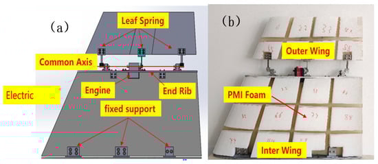
Figure 1.
Folded wing similar model: (a) SolidWorks designed model; (b) Experimental model.
The parameters of the core board were determined separately here due to the special nature of the core board in similar models. The core board was selected from resin, curing agent and glass fiber orthogonal woven fabric as the quasi-isotropic (0°–90°–45°–−45°) hand lay-up within the base surface, and two glass fiber composite core boards were laid with inner and outer wings, as shown in Figure 2a below, with wing thickness of 2.7 mm and outer wing thickness of 1.9 mm and 56% glass fiber content. The core board is laid to simulate the stiffness of similar models, so the tensile testing machine is used to measure the stiffness of the laid glass fiber plate, and the experiment is shown in Figure 2b.
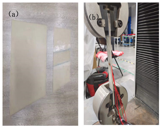
Figure 2.
Core board lay-up parameters: (a) inner and outer wing core board; (b) tensile test.
Five samples were selected from the core board for tensile experimental testing, and the experimental results were measured as follows Table 1. To reduce the experimental error, the average value of five specimens was taken for each property of the material, and the modulus of elasticity of the core board was 10 Gpa, Poisson’s ratio was 0.31, and the tensile strength was 250 Mpa.
3. Dynamic Testing Using Similar Models
3.1. Experimental Model Ground Test
An experimental model designed and manufactured based on the principle of functional similarity and structural similarity was used to carry out structural dynamics ground tests, and the similar model was mounted on the experimental platform at the root of the inner wing and excited by the hammering method. The vibration signal of the model is collected by the acceleration sensor pasted on the surface of the model, and the signal acquisition card transmits the collected data to the computer processor, and, finally, the post-processing software LMS Test Lab is used to fit the data to obtain the vibration frequency and vibration pattern of similar models, as shown in Figure 3 below.
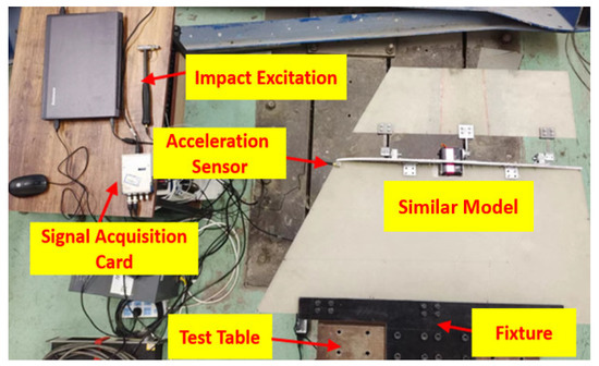
Figure 3.
Experimental model ground modal knockout experiment.
This section describes the process of importing geometric elements of the experimental model into the software. Firstly, the point set that can replace its geometry is selected on the surface of the test model; 16 points sets are selected for each of the inner and outer wing core plates, 32 in total, and the accelerometer is placed at point 16. Secondly, the geometric coordinate origin of the test model is selected, and the 32 points are fitted to the LMS Test Lab software in 3D coordinates. Finally, the geometric coordinate point sets are connected into a two-dimensional surface according to the geometry of the principal sample model The structure diagram is shown in Figure 4. Based on this experimental test, the vibration modes and vibration frequencies of different folding angles 0°, 30° and 60° are tested for experimental models.
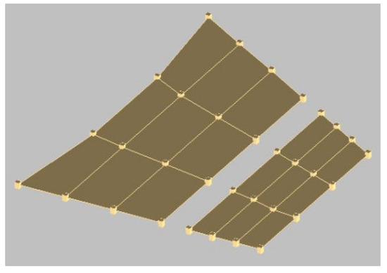
Figure 4.
Similar model ground test process.
3.2. Similar Model Finite Element Simulation
The designed model based on SolidWorks modeling is converted into a finite element model and then ABAQUS finite element simulation. The finite element model is shown in Figure 5 below, and elements such as material properties, connection relationships and boundary conditions of the manufactured similar model are given to the finite element model to ensure the accuracy and validity of the finite element simulation analysis score. The material parameters of the important parts are set in Table 2 below, and the material properties include their density, elastic modulus and Poisson’s ratio; the boundary conditions are set in two parts; one is the assembly relationship between the parts, the binding and contact between the faces, and the setting of the hinge connector; the other part is the fixation of the model and the experimental table, and the three-point fixed connection is used. After the simulation of similar models and comparing the experimental data with the simulation data, the differences are analyzed.
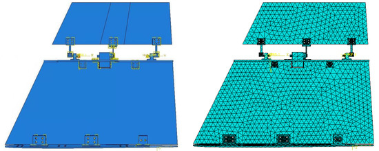
Figure 5.
Similar model finite element model.
Table 2.
Material properties of major components.
3.3. Finite Element Model Simplification Method
Due to the full-size similar model having many parts and a large geometric span, resulting in complicated boundary condition settings and tedious meshing steps, it is especially important to simplify or establish the finite element model reasonably without changing the dynamic characteristics of the model. It is important to simplify or establish the finite element model reasonably for the similar models designed and manufactured, and summarize the method of simplifying and establishing the finite element model, which not only helps to establish the finite element model quickly, but also improves the accuracy of simulation and the efficiency of calculation significantly. , where ω is the vibration frequency, Ke is the equivalent stiffness of the simplified system and Me is the equivalent mass of the simplified system. The factors affecting the vibration frequency of the structure mainly include the stiffness and mass of the structure, so different simplification methods are proposed for comparison according to the influencing factors.
The design of the inner wing root rib fixture is mainly to simulate the connection with the fuselage. In order to exclude the influence of the inner wing root rib on the vibration frequency of the model structure, the finite element model with omitted inner wing root rib is firstly simulated and calculated, and then transformed into a reasonable boundary conditions, which include constraints, loads and connections. The analysis results show that the vibration frequency of the finite element model with omitted inner wing root rib is within 0.1% error of the original model data, so the inner wing root rib of the finite element model is omitted first.
Based on the finite element model, this section proposes two methods to simplify the finite element model as shown in Figure 6. The finite element model established by the first simplification method is referred to as simplified model 1 as shown in Figure 6a, and the specific simplification methods are as follows: first, to reduce the influence of small geometric size parts and, therefore, omit the parts with relatively small geometric size in the finite element model, such as bolts, screws, spacers, etc.; second, considering that the parts that play the role of assembly and limit may bring the problem of preload, so they are omitted, such as T-plates, U-slots, end ribs, etc. Finally, all the omitted parts are transformed into real boundary conditions, which include loads, constraints, connections, etc. The finite element model established by the second simplified method is referred to as simplified model 2 as shown in Figure 6b, the second simplification method is based on the equivalent mass and equivalent stiffness of the structure, and since the end ribs are the parts that carry the whole folding area and outer wing, and the stiffness of the end ribs affects the overall stiffness of the model, the parts that provide stiffness to the model, such as the end ribs, are considered on the basis of the first simplified model. The vibration modes at the 0° folding angle are simulated and calculated for each of the two simplified models, and the simulation results are summarized.
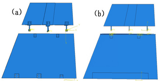
Figure 6.
Simplification of finite element model (a) simplified model 1, (b) simplified model 2.
4. Results and Discussion
4.1. Experimental Model Ground Test
It is found that the modal vibration patterns corresponding to experimental models in different folding angle states are very similar and the difference in vibration frequencies is within 10%. The first-order bending mode vibration frequency is 3.47 Hz when the folding angle of the similar model is 0 degrees, and the amplitude of the vibration pattern is gradually increasing from the root of the inner wing to the tip of the wing; the first-order torsional mode vibration frequency is 9.35 Hz, and the wing is twisted around its rotation axis; the second-order bending mode vibration frequency is 15.15 Hz, and the inner and outer wings of the wing show their respective bending deformation, and both the inner and outer wings show a regular and gradual increase from the inner end to the outer end; the second-order torsional mode vibration frequency is 24.16 Hz, and the inner and outer wings twist along the chordal axis of the wing, and the inner and outer wings twist in opposite directions. The second-order torsional mode vibration frequency is 24.16 Hz, and the inner and outer wings twist and vibrate along the leading and trailing edges of the chordal axis of the wing respectively, and the inner and outer wings twist in opposite directions, and the leading and trailing edges of the wing have the largest amplitude, while the root of the inner wing and the chordal axis have the smallest amplitude.
When the folding angle is changed, the vibration mode of the experimental model remains basically the same, and the difference in vibration frequencies of the same order does not exceed 10%. The vibration frequency and vibration pattern of the same test model remain basically the same under different folding angle states. Table 3 shows the vibration characteristics of the experimental model at different folding foot degrees.
Table 3.
Vibration characteristics of the experimental model at different folding foot degrees.
4.2. Finite Element Model Simulation Results
Considering that the external load may generate pre-stress, the gravitational field was applied, and the sensor mass point and the folding zone mass converted to a uniform load applied on the inner core board assembly surface. The effect of the results before and after the simulation was not significant, so the factors such as external load were withdrawn.
ABAQUS software was used to simulate the above finite element model at different angles, and the modal data are shown in Table 4 below. The simulation data found that the vibration frequencies of the finite element model in different folding angle states of the same order differed by less than 10%.
Table 4.
Finite element model simulation.
4.3. Characterization of Similar Models
Combining the test and finite element simulation results of similar models, the ground test and finite simulation vibration modal diagrams of similar models, it can be intuitively found that the airfoil vibration patterns obtained by the two approaches at different folding angle states match well; the vibration similarity Modal Assurance Criteria (MAC) values are also above 90%. Table 5 shows the vibration frequencies and their errors under different folding angles of the finite element model and the experimental model. In terms of the comparison of the vibration frequencies, the modal errors of each order for each folding degree of the simulation model and the experimental model are within 15%, and the modal errors of the first two orders under the three folding angles do not exceed 5%, so it can be proved that the established finite element model and its boundary conditions are highly accurate.
Table 5.
Vibration frequencies and their errors under different folding angles of finite element model and experimental model.
The study of the dynamic characteristics of the similar model is based on the similar model test and finite element simulation, and the finite element model parameters are adjusted according to the test data. The data show that the vibration modes obtained from the similar model finite element simulation have small vibration mode errors compared with the test data, so the finite element model established according to the test model and the boundary conditions set are reliable.
4.4. Analysis Results of Finite Element Simplified Model
The vibration modes of the structure with the folding angle at 0° are simulated for each of the above two simplified finite element models, as shown in Table 6 below. In the first-order bending mode of the simplified model 1, the inner wing’s bending level is obvious; however, the outer wing’s bending deformation of the leading edge is much smaller than the bending deformation of the trailing edge. The first-order torsional mode vibration pattern is not significant, the inner wing is bending in a vibration pattern, only the outer wing is in torsional mode and the deformation of the leading edge is much smaller than the deformation of the trailing edge. On the whole, the vibration patterns of the first two orders of the simplified model 1 are very different from the vibration patterns of the test model. The vibration patterns of the first two orders of the simplified model 2 are very significant; these are the first-order bending vibration pattern and the first-order torsional vibration pattern, and the overall match with the vibration pattern of the test model is very good. By visually comparing the differences between the vibration patterns of the finite element model and the test model, although the differences can be observed visually, it is still necessary to compare the vibration frequencies of the two simplified models and the test model, and further judge the validity of the finite element model based on the errors in their vibration frequencies.
Table 6.
Vibrational modes of the two FEM simplified models.
The vibration patterns of the two simplified finite element models are similar to those of the test model, so the vibration frequencies are further compared and analyzed and the errors in the simplified model compared to the test data are calculated as shown in Table 7 below. The data show that the first two orders of modal vibration frequencies obtained from the simplified model 1 after simplifying and omitting the inner wing end ribs and the folding area connections are very different from those of the test model, with the average error value above 80%, which can be considered as no similarity between the two; on the contrary, the average error value between the first two orders of modal vibration frequencies of the simplified model 2 and those of the test model is less than 4%.
Table 7.
Errors in the vibration frequency of the simplified model and the experimental model.
The data obtained from the simulation of the finite element model established by the two simplified methods were combined, and it was found that the dynamic characteristics of the finite element model established by the second simplified method were similar to the experimental model to a high degree. In particular, the first-order mode match was as high as 99%; however, the dynamic characteristics of the finite element model established by the first simplified method had a high degree of error compared with the experimental model. Therefore, the method of establishing the finite element model based on the principle of equivalent mass and equivalent stiffness of the structure is reliable.
The finite element model using ABAQUS software simulation calculation efficiency study found that, under the same conditions of dimensional mesh, analysis input file processor, etc., the original dimensional model simulation calculation of the first four orders of modal time spent 336 s; however, the second simplified method to build a simplified finite element model 2 time spent 83 s. In comparison, the simulation calculation time of simplified finite element model 2 is about 35% of the original size time, so a reasonable simplified finite element model can substantially improve the efficiency of finite element simulation.
4.5. Finite Element Model Modal Parameter Uptake Analysis
A particularly important part of the model design and manufacturing is to consider the modal parameters ingestion, by adjusting the geometric parameters of the components to obtain the required vibration mode of the target structure, the selection of components to ensure that the overall stiffness of the structure needs to be changed, but also to avoid the impact on the original structural mass distribution.
The x-axis rotational degrees of freedom of the leading- trailing edge spring are not limited, so its geometric parameters only adjust the torsional mode of the finite element model, but have no effect on the bending mode. The drive spring plate in the middle of the similar model provides the bending moment for the whole outer wing, so the geometric parameters of the drive spring plate mainly adjust the bending mode. For the similar model structure designed in this study, the first-order bending mode frequencies and first-order torsional mode frequencies obtained with the two sets of regenerative parameters are compared for the leading–trailing edge spring sheet and the drive spring sheet geometry parameters regeneratively, based on the simplified finite element model for fast simulation calculations, as shown in Figure 7 below.
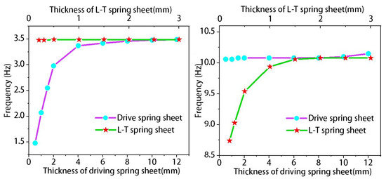
Figure 7.
Effect of leaf springs geometry thickness on the vibration frequency of similar models.
The thickness regression range of leading edge–rear edge spring plate is 0.2 mm–3 mm, and the thickness regression range of driving spring plate is 0.5 mm–12 mm. The first-order bending mode does not change when the thickness of the leading–trailing edge spring is changed from small to large, and the first-order torsional mode gradually increases until the vibration frequency is 10.08 Hz, which further indicates that the leading–trailing edge spring only plays a role in regulating the torsional mode, and its stiffness does not affect the vibration frequency of similar models when the thickness of the spring exceeds 2 mm. When the thickness of the driving spring is changed from small to large, the first-order bending mode of the structure gradually increases until the vibration frequency reaches 3.49 Hz and stabilizes, while the first-order torsional mode only has a slight change of less than 1%, so the driving spring plays a role in regulating the bending mode.
When a finite element model needs to adjust its vibration mode, adjusting the geometry of the leading–trailing edge spring and the driving spring is an effective way to do so. The leading–trailing edge spring adjusts the torsional mode of the similar model with a critical thickness of 2 mm, while the driving spring adjusts the bending mode of the similar model with a critical thickness of 8 mm. Spring plate geometry parameter ingestion can effectively adjust the vibration mode of similar models, leading edge–trailing edge spring plate adjusts the torsion mode, and driving spring plate adjusts the bending mode.
5. Conclusions
Based on the principle of functional similarity and structural similarity, the experimental model of a core board and dimensional structure folding wing can effectively simulate the dynamics of a folding wing, and can successfully complete the dynamics test and obtain reliable test data. The experimental model designed in this study avoids the decomposition of the folding wing into different configurations when the folding angle changes, thus reducing the errors caused by repeated modeling of different configurations of the wing.
The finite element model built from the experimental model and the boundary conditions set are highly reliable. The simulation data based on the similar model has a good match with the experimental data. The simulation data of the finite element model based on the similar model showed high agreement of vibration pattern and small error of vibration frequency compared with the test data.
Taking the finite element simplified modeling verification as a case study, we propose a fast method to build a finite element model, which not only maintains the advantages of high vibration shape fit and small vibration frequency error, but also improves the efficiency of finite element modeling and simulation analysis.
Author Contributions
Conceptualization, R.Y.; Methodology, X.L. and R.Y.; Validation, X.L. and W.Q.; Data Curation, R.Y. and X.L.; Writing—Original Draft Preparation, X.L.; Writing—Review and Editing, R.Y. and S.S.; Supervision, S.S. and W.Q.; Project Administration, R.Y. All authors have read and agreed to the published version of the manuscript.
Funding
This research was funded by the National Natural Science Foundation of China (No. 51975085) and the Fundamental Research Funds for the Central Universities ‘DUT21GF405’.
Conflicts of Interest
The authors declare no conflict of interest.
References
- Horta, L.G.; Kvaternik, R.G. A Historical Perspective on Dynamics Testing at the Langley Research Center; Dynamics Specialists Conference; NASA Langley Technical Report Server: Washington, DC, USA, 2000. [Google Scholar]
- French, M.; Eastep, F.E. Aeroelastic model design using parameter identification. J. Aircr. 1996, 33, 198–202. [Google Scholar] [CrossRef]
- Afonso, F.; Coelho, M.; Vale, J.; Lau, F.; Suleman, A. On the Design of Aeroelastically Scaled Models of High Aspect-Ratio Wings. Aerospace 2020, 7, 166. [Google Scholar] [CrossRef]
- King, J.P. A method for improving the dynamic response of full bridge reduced-scale models in aeroelastic wind tunnel tests by using optimization algorithms. J. Wind Eng. Ind. Aerodyn. 2017, 167, 198–216. [Google Scholar]
- Allen, T.; Sexton, B.; Scott, M.J. SUGAR Truss Braced Wing Full Scale Aeroelastic Analysis and Dynamically Scaled Wind Tunnel Model Development. In Proceedings of the 56th AIAA/ASCE/AHS/ASC Structures, Structural Dynamics, and Materials Conference, Kissimmee, FL, USA, 5–9 January 2015. [Google Scholar]
- Ricciardi, A.P.; Canfield, R.A.; Patil, M.J.; Lindsley, N. Nonlinear Aeroelastic Scaled-Model Design. J. Aircr. 2016, 53, 20–32. [Google Scholar] [CrossRef]
- He, K.F.; Mao, Z.J.; Wang, Q.; Hai, C. Demonstration and validation flight test of scale aircraft model and its key technology. Acta Aerodyn. Sin. 2017, 35, 9. [Google Scholar]
- Wang, L.; Zuo, X.; Liu, H.; Yue, T.; Jia, X.; You, J. Flying qualities evaluation criteria design for scaled-model aircraft based on similarity theory. Aerosp. Sci. Technol. 2019, 90, 209–221. [Google Scholar] [CrossRef]
- Cole, S.R.; Noll, T.E.; Perry, B. Transonic Dynamics Tunnel Aeroelastic Testing in Support of Aircraft Development. J. Aircr. 2003, 40, 820. [Google Scholar] [CrossRef]
- Galinski, C.; Bartkiewicz, P.; Hajduk, J.; Lamers, P. Results of the J-5 Marco Dynamic Similar Model Flight Tests Program. In Proceedings of the World Aviation Congress, Madrid, Spain, 12 February 2013. [Google Scholar]
- He, S.; Guo, S.J.; Liu, Y.; Luo, W.K. Passive gust alleviation of a flying-wing aircraft by analysis and wind-tunnel test of a scaled model in dynamic similarity. Aerosp. Sci. Technol. 2021, 113, 106689. [Google Scholar] [CrossRef]
- Coutinho, C.P.; Baptista, A.J.; Rodrigues, J.D. Reduced scale models based on similitude theory: A review up to 2015. Eng. Struct. 2016, 119, 81–94. [Google Scholar] [CrossRef]
- Dan, B.; Kroo, I.M. Aeroelastic Design Optimization of a Two-Spar Flexible Wind-Tunnel Model. J. Aircr. 2002, 39, 1074–1076. [Google Scholar]
- Chen, R. Investigations of the Method of Scale Model for Large Structures in Aeronautics and Astronautics. Ph.D. Thesis, Dalian University of Technology, Dalian, China, 2021. [Google Scholar]
- Qian, W.; Zhang, G.J.; Liu, Z.K. Flutter characteristics for aircraft all-movable horizontal tail through wind tunnel test. Acta Aeronaut. Et Astronaut. Sin. 2015, 36, 1093–1102. [Google Scholar]
- Cheung RC, M.; Rezgui, D.; Cooper, J.E.; Wilson, T. Testing of a Hinged Wingtip Device for Gust Loads Alleviation. J. Aircr. 2018, 55, 2050–2067. [Google Scholar] [CrossRef]
- Cheung, R.C.M.; Rezgui, D.; Cooper, J.E.; Wilson, T. Testing of Folding Wingtip for Gust Load Alleviation of Flexible High-Aspect-Ratio Wing. J. Aircr. 2020, 57, 1–13. [Google Scholar] [CrossRef]
- Cooper, J.E. A Parametric Study on the Aeroelasticity of Flared Hinge Folding Wingtips. Aerospace 2021, 8, 221. [Google Scholar]


Publisher’s Note: MDPI stays neutral with regard to jurisdictional claims in published maps and institutional affiliations. |
© 2022 by the authors. Licensee MDPI, Basel, Switzerland. This article is an open access article distributed under the terms and conditions of the Creative Commons Attribution (CC BY) license (https://creativecommons.org/licenses/by/4.0/).